易威奇(iwaik)MD磁力泵使用说明书
易威奇计量泵
磁力泵一、启动前的准备和检查1、检查泵的有关配管联接就绪,泵体附件完好,电气仪表符合要求。
2、检查泵油箱装填符合标准的润滑油,润滑油无变质,并到指定油位。
3、有联轴器的泵需手动盘车、检查各转动部分是否灵活,有无不正常的卡死,杂音情况,无阻力感和磨擦感。
4、打开泵入口阀及泵出口线上排气阀,进行排气,使泵内充满液体,然后关闭排气阀。
排气时,也可轻轻地转动轴,使泵内气体完全排出。
5、点试泵,确认泵的旋转方向是否正确,轴承和泵体无异常振动和噪音,压力正常,如一切正常,泵停止转动5分钟后可启动泵。
二、磁力泵的启动:1、全闭排出阀。
2、接通电源,待泵运转到额定转速。
3、如果需要,再次打开排气阀进行排气,直到彻底无气后,再关闭排气阀。
4、注意电流,缓慢打开出口阀,注意不要超负荷。
使压力、流量达到额定数值。
5、检查泵的轴承、油位、工作状态、机体振动、噪音、泄漏、温度等状况有无异常。
三、停泵1、逐渐关闭出口阀。
2、切断电源。
3、关闭入口阀。
4、盘车,检查泵转动的灵活性。
5、将泵内介质放出四、磁力泵的切换注意:原则上切换时应保持系统流量、压力保持不变,严禁抽空、抢量等现象发生。
1、备用泵应做好一切启动准备工作。
2、打开备用泵入口阀,并排气。
3、启动备用泵至额定转速,检查振动、泄漏、温度等,然后注意电流变化,逐渐打开备用泵出口阀,同时在保持流量、压力不变的情况下,逐渐关闭被切换泵的出口阀。
当备用泵达到额定压力和流量时,关闭被切换泵的排出阀并切断电源,对其做停泵后的处理。
五、磁力泵操作注意事项:1、磁力泵在任何情况下,不允许在无润滑措施下运行,以免损坏机件。
2、不允许在入口阀不开的情况下启动泵,做断流运转。
3、不允许停泵后,不关闭出口阀门。
4、只允许用出口阀调节流量、压力,不可用入口阀调节。
六、泵正常运转时检查要点。
1、检查泵出口压力、出口流量是否满足工艺要求。
2、轴承箱温度是否过高,轴承箱温度不能高于70℃或环境温度+40℃。
磁力泵安全操作规程(格式规范)

磁力泵安全操作规程
1.磁力泵的运行
1.1运行前的准备工作
1.1.1管道必须进行吹扫、清洗、为防止残留的杂质、焊渣进入泵腔,在泵进口处须配有过滤器或过滤网。
1.1.2检查名部分螺栓、连接件是否有松动,有松动的要加以坚固。
1.1.3用手盘动联轴节,使泵转子转动几圈,看转动是否灵活,是否有响声或轻重不匀的感觉,以判断泵内有无异物。
1.2启动程序
1.2.1打开进口阀门,关闭出口阀门、压力表阀,进行灌泵。
1.2.2稍开出口阀,点动电动机,查看电机转向。
1.2.3转向正确后,启动电动机,打开压力表。
1.2.4在压力上升并认为机器运转开稳后,徐徐打开出口阀,泵进行正常工作。
1.2.5泵运行点应在工况点上下浮动,过小、过大流量均易造成泵损坏。
绝不允许用吸入管路上的阀门来调节流量,以免产生气蚀。
2.磁力泵的停车
2.1缓慢关闭出口阀。
2.2停止电机。
2.3关闭泵进口阀门。
2.4如环境温度低于液体凝固点时,要放净泵内液体,以防冻裂。
2.5长时间停止使用的泵,除将泵内的腐蚀性液体放净外,还要用清水冲洗干净,尤其是密封室认真冲洗干净。
2.6禁止在出口阀门未关闭的情况下停车,以免出口管路液体倒流使叶轮反转,损坏零件。
3.磁力泵操作中注意事项:泵决不允许空载运行,一旦断液或泵内有摩擦,立即停泵,防止泵空载而造成进一步的损坏。
磁力泵操作规程
磁力泵操作规程《磁力泵操作规程》一、引言磁力泵是一种无泄漏的泵,它利用磁力驱动叶轮旋转,从而实现液体的输送。
由于磁力泵没有机械密封,因此可以避免泄漏问题,特别适用于输送易燃、易爆、有毒、有害等危险液体。
二、适用范围本操作规程适用于所有类型的磁力泵,包括卧式磁力泵、立式磁力泵、管道磁力泵等。
三、设备组成及工作原理设备组成 磁力泵主要由泵体、叶轮、磁力驱动器、隔离套、滑动轴承、止推轴承、轴套、泵盖、底座等组成。
工作原理 磁力泵的工作原理是利用磁力驱动器将电机的旋转运动转化为叶轮的旋转运动,从而实现液体的输送。
磁力驱动器由外磁转子、内磁转子和隔离套组成,外磁转子通过电机带动旋转,内磁转子通过磁力耦合与外磁转子同步旋转,从而带动叶轮旋转。
隔离套将内磁转子和外磁转子隔开,防止液体进入磁力驱动器内部,从而保证了磁力驱动器的安全运行。
四、操作前准备操作人员必须经过专业培训,熟悉磁力泵的操作方法和安全注意事项。
操作人员必须穿戴好劳动防护用品,如工作服、手套、护目镜等。
操作人员必须检查磁力泵的各部件是否正常,如泵体、叶轮、磁力驱动器、隔离套、滑动轴承、止推轴承、轴套、泵盖、底座等是否有损坏或松动。
操作人员必须检查磁力泵的进出口管道是否连接牢固,阀门是否打开。
操作人员必须检查磁力泵的电气系统是否正常,如电源、开关、电机等是否有故障。
操作人员必须检查磁力泵的润滑系统是否正常,如润滑油是否充足,润滑管路是否畅通。
操作人员必须检查磁力泵的冷却系统是否正常,如冷却液是否充足,冷却管路是否畅通。
操作人员必须检查磁力泵的密封系统是否正常,如密封件是否损坏,密封面是否清洁。
操作人员必须检查磁力泵的周围环境是否安全,如周围是否有易燃易爆物品,是否有障碍物等。
操作人员必须检查磁力泵的进出口压力是否正常,如进出口压力是否超过磁力泵的额定压力。
1. 2. 1. 2. 3. 4. 5. 6. 7. 8. 9. 10.操作人员必须检查磁力泵的进出口流量是否正常,如进出口流量是否超过磁力泵的额定流量。
磁力泵操作规程

磁力泵操作规程一、引言磁力泵是一种采用磁力传动的无泄漏密封泵,广泛应用于化工、医药、食品等行业。
为了确保磁力泵的安全、高效运行,制定本操作规程,以规范磁力泵的操作流程和注意事项。
二、操作人员要求1. 操作人员必须经过专业培训,具备相关操作技能,并熟悉磁力泵的结构和工作原理。
2. 操作人员必须严格遵守安全操作规程,佩戴个人防护装备,如安全帽、防护眼镜、防护手套等。
3. 操作人员必须了解磁力泵的性能参数和操作限制,遵守设备的使用说明书。
三、操作步骤1. 准备工作a. 检查磁力泵的外观是否完好,是否有异物堵塞。
b. 检查电源线是否正常,接地是否良好。
c. 检查泵的进出口阀门是否打开。
d. 检查泵的轴承是否润滑良好。
2. 启动磁力泵a. 将电源线插入正常的电源插座。
b. 按下启动按钮,观察磁力泵的运行情况。
c. 注意观察磁力泵的噪音和振动情况,如有异常应及时停机检修。
3. 调整磁力泵的流量和压力a. 根据工艺要求,调整进出口阀门的开度,控制流量。
b. 根据工艺要求,调整泵的转速或电机功率,控制压力。
4. 监控磁力泵的运行状态a. 定期观察磁力泵的液位和温度,确保在正常范围内。
b. 注意观察磁力泵的压力表和流量计的读数,如有异常应及时处理。
c. 定期检查磁力泵的密封性能,如有泄漏应及时检修。
5. 停止磁力泵a. 当工艺结束或需要停机时,先关闭进出口阀门。
b. 按下停止按钮,断开电源。
四、安全注意事项1. 操作人员严禁戴手套或长袖衣物进行操作,以免被卷入磁力泵的旋转部件造成伤害。
2. 操作人员在操作过程中,应保持警惕,注意观察磁力泵的运行情况,如发现异常应及时停机检查。
3. 禁止在磁力泵运行时进行维修、清洁等工作,必须先停机并切断电源。
4. 在磁力泵运行过程中,严禁随意调整进出口阀门的开度,以免影响设备的正常运行。
5. 操作人员必须熟悉应急处理措施,如发生泄漏、火灾等情况,应立即采取相应措施并报告上级。
五、紧急情况处理1. 如发生泵体过热、异响、泄漏等异常情况,应立即停机并切断电源,进行检修。
磁力泵操作规程

磁力泵操作规程1.磁力泵的运行1.1试车前的准备工作管道必须进行吹扫、清洗、为防止残留的杂质、焊渣进入泵腔,在泵进口处须配有过滤器或过滤网.检查名部分螺栓、连接件是否有松动,有松动的要加以坚固.用手盘动联轴节,使泵转子转动几圈,看转动是否灵活,是否有响声或轻重不匀的感觉,以判断泵内有无异物.1.2启动程序打开吸入阀<进口阀>,关闭排出阀〔出口阀〕、压力表阀、真空表阀,进行灌泵.稍开排出阀,点动电动机,查看电机转向.转向正确后,启动电动机,找开压力表、真空表阀.在压力上升并认为机器运转开稳后,徐徐打开排出阀,泵进行正常工作〔离心泵排出阀微开启动,是为了轻载起步,减小点动电流,但必须注意:旋涡泵必须开阀启动〕.泵运行点应在工况点上下浮动,过小、过大流量均易造成泵损坏.绝不允许用吸入管路上的阀门来调节流量,以免产生气蚀.2.磁力泵的停车2.1缓慢关闭排出阀.2.2停止电机.2.3关闭泵进口阀门.2.4如环境温度低于液体凝固点时,要放净泵内液体,以防冻裂.2.5长时间停止使用的泵,除将泵内的腐蚀性液体放净外,还要用清水冲洗干净,尤其是密封室认真冲洗干净.最好是将泵拆下清洗后重新装好,并将泵的进出口封闭后妥善保管.2.6禁止在出口阀门未关闭的情况下停车,以免出口管路液体倒流使叶轮反转,损坏零件.3.磁力泵操作中注意事项3.1泵决不允许空载运行,如果不能保证,须安装空载保护装置,压力传感器或负载测控器.一旦断液或泵内有摩擦,则保护装置响应后跳闸,防止泵空载而造成进一步的损坏.3.2如果磁力泵配备的电机超过7.5KW,最好能配备慢启动装置〔如星三角启动器〕.因为电机启动时,启动扭矩大,而配备的磁钢扭矩如果小于起动扭矩时,则内外磁钢会出现滑脱现象,即外转子转动而内转子不动,导致涡流热不能与时排出,引起温度极度升高,而最终使得内外联轴器退磁,无法运行.3.3如果泵内有易凝固的介质,则开车前须先通蒸气,等介质充分溶化后,方可开车运行.3.4在离心泵试运转中,要检查整个系统有无漏气、漏液,性能是否符合要求,机组有否较大的振动和不正常的响声,在各方面都认为合格后,方可投入运转.4.磁力驱动泵维护和保养磁力泵必须作好日常的维护和保养工作,才能有效地发挥泵良好性能,延长泵的使用寿命.4.1运行中上监视和维护:泵在运行中,要加强对机组的巡视工作,与早发现异常,尽快作出处理.在巡视中,一般要随时留意下列几个方面:注意机组的响声和振动情况是否正常.观察电流表、电压表、压力表、真空表和流量计等仪表读数是否正常.注意管路是否有漏气、漏液等.平时保持机组的清洁,并注意操作安全.4.2运行后的保养在寒冷的季节,尤其在室外的泵,在停车后应立即去掉泵内液体,以防结冰冻.一般的备用泵,也应定时启动一次.泵要定时检修,检查并更换不合格的易损件,如轴承、轴套、止推环等.轴承箱中的润滑脂要定期添加.5.泵运行中的常见故障与其排除方法磁力泵在运行中出现的常见故障,可分为两类:一类是泵输液工作性能变坏,如流量减小,扬程降低,发生气蚀等.这类故障称性能故障〔亦叫水力故障〕;另一类故障是机械上的问题,如轴承烧坏,轴弯曲,叶轮断裂等,系机械故障.造成故障的原因很多,可能是选型与安装不正确,或者是操作维护不得法,又或者是原动机的问题等等.现将常见的故障现象和可能引起的原因,以与排除方法,列于下表.故障与防治磁力泵操作注意事项1、泵在调试时,假如单一试电机,可以拆掉中间连轴节,重新安装时必须对中.如果不拆电机调试磁力泵,必须保证泵腔充满液体,在泵没有空载的情况下进行,可以先点动电动机,看转向,当转向正确后,正式启动泵.2、第一次开车时,管路里会有空气,可在管路上装上排气孔.在开车前先排气,再启动磁力泵.3、磁力泵启动前,先盘动磁力泵外联轴器,当盘动外联轴器轻松灵活无杂声时,则开始启动泵.并且,还应在进口阀门全开,出口阀门微开或关闭时进行.当电机正常运转时再慢慢开启出口阀.4、磁力泵使用必须在样本中所规定流量、扬程点的X围内使用〔一般在额定的40%—120%之间运行〕.5、泵运行后调整出口阀,调至所需流量或规定流量,运行时应检查压力、流量、振动、噪音.如果液体有汽化现象〔表现为压力表指针晃动或泵进口处有杂音〕需减小出口阀门开度,减少流量来排除故障.6、泵停车时为了防止液体倒流引起倒转,应先关出口阀,再停电机,进口阀门可以不关闭7、当温度降至冰冻时,泵壳里可能有一些水冰住了叶轮,而泵转不动,在这种情况下,请先把冰溶了再开车.8、磁力泵严禁空载运转,每台磁力泵必须配置欠流保护器,当空载或过载时,保护器响应自动切断电源而停车.已经配置保护器的,按照要求对保护器予以设定.操作工应对上述应知应会,严禁违规操作.磁力泵操作规程启动前的准备工作 a 清理设备周围影响设备和操作人员安全的杂物. b 检查密封水槽内的工艺水是否在正常工作液位,不足时应补加. c 检查密封水管道上所有阀门要开关正确. d 在长期停机或泵检修后第一次开车时,拆下电机的风扇罩并手动盘车,检查磁力泵转动是否灵活,在确认没有问题后装好风扇罩. e 打开泵的进口阀,关闭泵的出口阀. f 通知电工向现场操作盘送电.启动 a 启动泵,检查泵的声音与振动情况. b在确认没有异常的情况下打开泵的出口阀.正常停车关闭出口阀,然后立即停止电动机,随后再关闭进口阀.紧急停车立即停止电动机,然后再关闭出口阀和进口阀.运行中注意事项 a 注意吸入端过滤器的前后压力差,压力差增加时,表示过滤器上有异物堵塞,要停止泵运行,以便清洗粗滤器. b 排出量、排出压力是否符合规定值; c 有无异常声音与振动,若发生异常声音或振动,一般情况说明有气蚀或轴承过度磨损. e 泵是否发生气蚀:打开泵的出口阀门,当流量达到一定量,突然发出响声和振动,这时继续开大阀门,如果流量仍不增加,说明有气蚀.有气蚀时要进行排气操作.注意:磁力泵在气蚀状态下绝对不能运转,如果在这种状态下继续运转,则会引起轴承早期磨损. f电动机的电流值是否超过额定电流. g 泵各部位的温度有无异常过热的状况. h 氮气稳压系统的压力应保持在规定的X围内1.一定要注意灌泵充分,因为磁力泵的轴承大部分是非金属材料的.2.磁力泵操作温度要注意,不能超温,否则会造成磁力转子脱磁,效率下降,扬程达不到设计要求,甚至完全失效,要更换磁力套.。
IWAKI磁力泵
141.52. .............................................................................................................................................................................................................................................................................................................................................................................................................................................................................................................................................................................................................................................................................................................................................................................................................................................................................63. 74. (8)..........................................................................................................................................................................................................................................................................................................................................................................................................................................................................................................95. ...............................................................................................................................................................................................................................................................................................................................................................106. 117. 13148. ...........................................................................................159. 10. 161711. 1812. 2013. 2014. 2715. 35 谢谢您选用易威奇MDM系列磁力驱动泵。
磁力泵安全操作规程

磁力泵安全操作规程
一、操作人员必须经过严格培训,熟悉磁力泵的型号、性能、基本构造、日常维护及保养等注意事项。
二、操作人员必须严格遵守《安全操作规程》、交接班制度、岗位责任制。
三、启动前检查:
1、手动盘动联轴器,盘车过程无卡阻及异常声音;
2、检查泵进出管路是否畅通,所有螺栓,接头是否紧固;
3、检查接地线是否已规范接地;
4、检查被输送储罐内液位。
四、操作流程
(一)启动
1、全开泵进出口管路所有阀门,手动盘动联轴器,让液体充满泵腔。
2、关闭泵出口阀门,启动泵,待泵达到正常转速后,逐渐打开出口管路阀门,
调节至所需工况(流量或压力)。
3、泵运行中检查泵的运行电流,原则上运行电流在额定功率的1.2~2倍之间。
同时还需要检查泵的声音及振动有无异常,如果发现异常情况应及时处理。
4、磁力泵设有空载及超载保护,在出口阀门关闭的情况下,泵的连续运行时
间不得超过2分钟。
(二)停泵
1、磁力泵停泵前先关出口阀门,然后停泵。
2、短时间内停泵不用关闭进口阀门,长时间停泵必须关闭进口阀门。
五、注意事项
1、磁力泵严禁空转,启动泵之前必须确认泵体充满液体。
2、电机运行温升≤75℃。
3、泵进口必须安装有过滤器,防止固体颗粒物对内磁及隔离套造成磨损。
4、冬季长时间停泵时必须将泵内液体放尽。
5、磁性联轴器采用高性永磁材料,请将心脏起搏器、信用卡及其它磁卡、手
机、手表等与磁力泵保持距离。
第 1 页。
iwaki泵浦MD操作手册
IWAKI Magnetic Drive Pump MD-R (M) typeInstruction ManualRead this manual before use of productThank you for selecting an Iwaki MD-R type Magnetic Drive Pump. This instruction manual deals with "Safety Instructions ", "Outline ", "Installation ", "Operation " and "Maintenance " sections.Please read through this instruction manual to ensure the opti-mum performance, safety and service of your pump.For the Safe andCorrect Handling of the Pump● "Safety Instruction" section deals with important details about handling of the product. Before use, read this section carefully for the prevention of personnel injury or property damage.● O bserve the instructions accompanied with "WARNING" or "CAUTION" in this manual. These instructions are very impor-tant for protecting pump users from dangerous situations.● The symbols on this instruction manual have the following meanings:This instruction manual should be kept on hand by the end userfor quick reference.Contact us or your nearest dealer if you have any questions.in the category of technology contained in the Foreign Exchange Order Attachment, which includes complementary export control of technology. Please be reminded that export license, which is issued by the Ministry of Economy, Trade, and Industry could be required, when this is exported or provided to someone even in Japan.ContentsSafety Instructions ··········································································1Outline1. Unpacking & Inspection ·······································32. Operating principle ···············································33. Identification code ················································44. Specification ·························································55. Outer dimensions ·················································66. Performance curves ·············································97. Overview & Label ···············································118. Part names & Structure ······································12Installation1. Before installation ···············································132. Installation/Piping/Electrical wiring ·················16Operation1. Before operation ..................................................22Maintenance 1. Troubleshooting .. (24)2. Maintenance & Inspection (24)Power offProhibitedProhibitedProhibitedNo modificationNo dismantlementCautionCaution● T urn off the power.R isk of electrical shock. Dismantling/assembling the pump unit without turn-ing off the power may cause an electrical shock. Before engaging in any maintenance or inspection work, be sure to turn off the pump and related devices.● Terminate operation.O n sensing any abnormality, stop operation immediately and inspect/solve problems.● For specified application onlyT he use of the pump in any application other than those clearly specified may result in injury or damage. Use the pump in aspecified condition.● No dismantlement/modificationD o not dismantle/modify the pump. We are not responsible for any accidents or damagedue to modification.● Wear protective clothing.A lways wear protective clothing such as safety goggles and protective gloves duringpipework or dismantlement.● Restriction on operatorT he pump should be handled by a qualified person with a full understanding.● Specified power onlyD o not apply any power other than the specified one on the nameplate. Otherwise damage or fire may result.● Do not wet the pump.I f a liquid spills over electric parts or wires, a fire or electrical shock may result. Install the pump in a place free from liquid spillage.● VentilationP oisoning may result when handling a toxic or odorous liquid. Keep good ventilation in a work area.● Countermeasure against effluxTake a protective measure against the acci-dental efflux caused by pump or pipe break-age.● Damaged pumpsD o not use any damaged pump. Using a damaged pump may lead to an electric leakor shock.ProhibitedProhibitedProhibited● Do not place the pump close to water.T he pump is not dust-/water-proof construc-tion. The use of the pump in a humid place or a place where the pump can get wet may result in an electrical shock or short-circuit.● D o not run pump dry.If the pump runs without a liquid, the pump is damaged by friction heat.● Do not damage the power cable.R isk of fire or electrical shock. Do not scratch, modify, or pull the power cable. The cable can also be damaged when it is heated or loaded with a heavy thing.● E arthingRisk of electrical shock. Always earth the pump.● D o not pressurize the pump over the maximum discharge pressure.A leak may result from the sealing surface of O ring, or the pump fails at worst.● I nstall an earth leakage breaker.An electrical failure of the pump may ad-versely affect related devices. Purchase and install an earth leakage breaker separately.● Power cable is not replaceable.D o not use any damaged power cable for the prevention of a fire or electrical shock. The cable is not replaceable, so that the whole pump unit needs to be replaced when the cable is damaged.● Limited operating site and storageD o not install or store the pump in the fol-lowing places where...1. A mbient temperature exceeds 40°C or falls below 0°C.2. U nder a flammable/corrosive atmosphere.3. Under direct sunlight or rainwater ● D isposal of the used pumpDispose of any used or damaged pump in accordance with relevant regulations. Consult a licensed industrial waste products disposing company.● Static electricityW hen low electric conductivity liquids such as ultra-pure water and fluor inactive liquid (e.g. Fluorinert TM ) are handled, the static electricity may generate in the pump and may cause static discharge. Take counter-measures to remove the static electricity.● Fasten the front casing tightLiquid may leak if front casing fixing screws are loose. Tighten the screws before initialoperation or at intervals.CautionProhibitedElectrical shockEarthingCautionProhibitedElectrical shockProhibited2. Operating principleThe MD-R is a magnetic drive centrifugal pump.The magnetic force of the motor drives the impeller mag-net and rotates the impeller in the pump chamber, where a liquid is transferred from the inlet to outlet.Before use, check the specification, limitation and hazardous nature of the pump.1. Unpacking & InspectionOn unpacking the product, check the following points. If you find any problems, contact your nearest distributor.1. C heck the information on the nameplate such as model, dis-charge capacity, discharge head and voltage to see that the prod-uct is delivered as per order.2. Check for transit damage, deformation, and loose bolts.Inlet3. Identification codeMD-15R/ -20R/ -30R/ -40RMD - 15 R Z - 5 M - 220 E N 01a b a c d e f g ha. S eries model MD-Rb. P ump size (motor output)15(10W)/ 20(20W)/ 30(45W)/ 40(65W)c. D elivery head No code: Standard Z: High head X: High flowd. F requency No code: 50/60Hz -5: 50Hz onlye. Connection No code: TubeM: G threadf. Power voltage220:220-240 single phaseg. O ring No code: FKME: EPDMh. Special version No code: Standard01-99: SpecialdesignMD-55R/ -70R/ -100RMD - 70 R Z - 5 M - 01a b a c d e fa. S eries modelMD-Rb. P ump size (motor output)55 (90W)/ 70 (150/180W, 180/216W)/100 (265W)c. D elivery head No code: Standard Z: High headd. F requency No code: 50/60Hz -5: 50Hz onlye. Connection No code: Tube M: G threadM-FL: Flangef. Special version No code: Standard01-99: Special design NOTE: T he MD-55R/ -70R/ -100R do not show a power volt-age code. See a spec label and check power voltagerange.4. Specification 50/60HzModel Hose bore(mm)Inlet/Out-let boreUnion Max flow (L/min)Max head (m)Max SG MotorMass (kg)Power(V)Rated output (W)MD-15R 14G3/41316/19 2.4/3.4 1.3220/240(1ph)10 1.6MD-20R 18G3/41627/31 3.1/4.3 1.1202.0MD-20RX 26G12046/52 1.8/2.5 1.3MD-20RZ 18G3/41310/11 4.9/6.9 1.1MD-30R 20G3/41632/38 3.8/5.4 1.3454.0MD-30RX 26G12062/72 2.9/4.1 1.1MD-30RZ 18G3/41315/178/11 1.0MD-40R 20G3/41645/52 4.6/6.5 1.1653.9MD-40RX 26G12075/85 3.3/4.7 1.1MD-40RZ 20G3/41622/2210/13.5 1.0MD-40RZ-520G3/41611/-11.5/- 1.0MD-55R 26G12060/70 5.6/8.2 1.290 5.4MD-55R-526G12070/-8.2/- 1.2MD-70R 26G12086/97 6.7/9.7 1.0220/240(1ph)220/380(3ph)400/440(3ph)150/180 6.0MD-70RZ 20G3/41640/4314.3/20.3 1.0180/216 6.0MD-100R 26G120120/1358.6/11.91.2260/2658.5MD-100R-526G120135/-11.7/- 1.1NOTE:a. P erformance data is based on pumping of clear water at ambient temperature.b. T he maximum flow is obtained at zero discharge head, and the maximum head is obtained at the maximum pressure.c. T he maximum viscosity at SG.1.0 is up to 30mPa•s for the MD-15R/-20R/-30R/-40R/-55R/-70R, up to 6mP•s for the MD-100R(M), and up to 4mP•s for the MD-100R-5(M).d. A llowable ambient temperature range is 0-40°C.e. A llowable liquid temperature range is 0-80°C.* N ote that the liquid temperature range is based on pumping clean water and it changes with liquid property and operat-ing conditions. Frozen liquid can not be transferred.f. T he maximum specific gravity is obtained at or near the maximum flow. Note that the limitation varies with a duty point, ambient temperature or liquid viscosity.g. M otor typeMD-40RZ-5(M), MD-55R-5(M), MD-100R-5(M) is designed for operation at 50Hz only.h. A ll the single-phase motors used for the MD-R series are capacitor-run induction motor.* P erformance and dimensions may change without notice.MD-20RXM/-30RXM/-40RXMModel W H L a b c d e G MD-20RXM 851322203050685546.5143MD-30RXM 12014025440641006050175MD-40RXM 12014125640641006050175MD-15R/-20R/-30R/-40RModel W H L a b c d e f G MD-15R 95109179.5-5068553921.5117MD-20R 85115208.53050685538.528.5131.5MD-30R 1201302484064100604831169MD-40R 12013025040641006048311695. Outer dimensionsMD-15RM/-20RM/-30RM/-40RMModel W H L a b c d e f G MD-15RM 95114179-5068553921.5117MD-20RM 85116203305068553328.5126MD-30RM 1201302484064100604831169MD-40RM 1201302504064100604831169Lea bGc WdHfLea bGc WdHLea bGc WdHfMD-55R/-55R-5Model W H L a b c d e f GMD-55R 120155273.540641006561.540198.5MD-55R-5MD-20RZM/-30RZM/-40RZM/-40RZ-5MModel W H L a b c d e f G MD-20RZM 851252113050685539.538.5134MD-30RZM 12013023040641006039.538.5152MD-40RZM 12015024140641006038.544.5160MD-40RZ-5M 12015024140641006038.544.5160MD-20RX/-30RX/-40RXModel W H L a b c d e G MD-20RX 851322203050685546.5143MD-30RX 12013725440641006050175MD-40RX 12013725640641006050175MD-20RZ/-30RZ/-40RZ/-40RZ-5Model W H L a b c d e f G MD-20RZ 851252113050685539.538.5134MD-30RZ 12013023040641006039.538.5152MD-40RZ 12015024140641006038.544.5160MD-40RZ-512015024140641006038.544.5160Lea bGc WdHLeGc WfdHabLea bGc WdHfMD-55RM/-55R-5MModel W H L a b c d e f GMD-55RM 120155273.540641006561.540198.5MD-55R-5MMD-70R/-70RZ/-100R/-100R-5Model W H L a b c d e f G MD-70R 1301552584060110655343179MD-70RZ 1652474247.5168MD-100R 15617532270100110756543.5197MD-100R-5Lea bGc W dHfLea bGc WdHfMD-70RM/-70RZM/-100RM/-100R-5MModel W H L a b c d e f G MD-70RM 1301552584060110655343179MD-70RZM 1652474247.5168MD-100RM15617532270100110756543.5197MD-100R-5MLea bGc WdHf6. Performance curves60Hz501020304020255ℓ/minm 101550Hz5MD-70RZMD-40RZ* A sound level of running water will increase when a delivery head drops to 6m or below.* A sound level of running water will increase when a delivery head drops to 7.5m or below.105102030040RZ40RZ-550HzmL/min105102030060Hz40RZmL/minMotor (drive unit)Do not wet the pump and motorunits.■ AccessoryTube joints are available for pumps with thread connec-tion.Model Inlet/Outlet boreO ring Hose joint bore MD-15RM G3/4AS-568-01613A MD-20RM G3/4AS-568-01716A MD-20RXM G1AS-568-02020A MD-20RZM G3/4AS-568-01613A MD-30RM G3/4AS-568-01716A MD-30RXM G1AS-568-02020A MD-30RZM G3/4AS-568-01613A MD-40RM G3/4AS-568-01716A MD-40RXM G1AS-568-02020A MD-40RZM G3/4AS-568-01716A MD-40RZ-5M G3/4AS-568-01716A MD-55RM G1AS-568-02020A MD-55R-5M G1AS-568-02020A MD-70RM G1AS-568-02020A MD-70RZM G3/4AS-568-01716A MD-100RM G1AS-568-02020A MD-100R-5MG1AS-568-02020A7. Overview & LabelInletBaseFix the pump securely.Specification labelUse the pump accord-ing to the specifica-tions on the label.OutletPump unit (Liquid feeding unit)Not capable of self-priming. Always primethe pump before operation.8. Part names & StructureNo.Part names Q'ty Materials Remarks1Front casing 1GFRPP 2Bearing 2PTFE 3Rear casing 1GFRPP 5O ring 1FKM 6Impeller 1GFRPP8Spindle 1Alumina ceramic 9Thrust ring 2Alumina ceramic 15Machine screw 4-6Stainless steel101Motor1101283515619NOTE1. M D-40RZ, -70RZ, -100R and -100R-5 have a CFRPPimpeller.NOTE2. E PDM O ring is available.NOTE3. M D-20RZ, -30RZ, -40RZ and -70RZ have a PPSbearing.1. Before InstallationRead through this instruction manual before use. Carry●D ropping or subjecting the pump to strong impact, failure may result. Handle the pump with care.●T he pump is not capable of self-priming. Always prime the pump before operation.●T he motor is not water-/dust-proof. Do not wet the motor, or it may fail.●T he pump doesn't have anON-OFF switch. The pump startsas the power cable is plugged in.● B anned solutions • H alogenated hydrocarbons such as trichloroethylene and carbon tetrachloride • E ther and low-grade ester • S lurry (Never use slurry, which wears out the pump bearings.)● A strong magnet is inside the pump. Do not use the pump with any liquid which contains metals such as iron and nickel.● D o not pull or knot the power cable or place a heavy stuff on it. Dam-age to the power cable could lead to a fire or electrical shock.● D o not use any damaged pump. Using a damaged pump may leadto an electric leak or shock.the following places where...1. A mbient temperature exceeds 40°C or falls below 0°C.2. I n a dusty/humid place.3. U nder direct sunlight or wind & rain.● I nstall the pump as close to a sup-ply tank. Keep a liquid level in the tank higher than the pump at any time.● A n electrical failure of the pump may adversely affect related devic-es. Purchase and install an earthleakage breaker separately.NickelIron● N oise level during operation is as below.ModelNoise level MD-15R 40dB MD-20R 45dB MD-20RX 50dB MD-20RZ MD-30R 55dBMD-30RX 60dBMD-30RZ MD-40R MD-40RX MD-40RZ MD-55R 55dB MD-70R 70dB MD-70RZ MD-100R75dB*Noise level is measured in A scale at a distance of 1m.2. Installation/ Piping/ Electrical wiringS top working upon sensing danger or abnormality in work.2.1 Installation1. Installation locationSelect a convenient place for maintenance and inspection. Observe the allowable room temperature range of 0-40°C and the allowable maximum ambient humidity of 90%RH.2. Mounting positionT his pump is not capable of self-priming. Flooded suction application is ideal. The pump should be installed 30cm lower than the suction liquid level, or the bearing may be worn soon by entrained air.3. O utlet directionA lways direct the outlet upward or entrained air can not be expelled.4. D o not mount the pump vertically.5. Pump fixationSecure the pump by fixing the base on a flat and a stable foun-dation.NOTE: U se corrosive resistant fixingscrews.Direct the outlet upwardDo not make itupright2.2 Piping■ Before tubing• U sing a high flow pump and small supply tank, a liquid level in the tank changes greatly.• D o not allow a drop of adhesive agent or sealant into pipe-work. They may cause fatal damage to the pump.• I f pipework directory weighs on the pump, deformation or damage may result. Be sure to install pipe supports. Plumbing layout 1. Flow/head adjustment & maintenance valvesI nstall a ball valve on a discharge line for flow rate adjust-ment and on a suction line for the convenience of mainte-nance, as close to the pump as possible.2. P ressure gaugeInstall a pressure gauge for monitoring discharge line pres-sure.3. D rain valveInstall a drain valve in between the pump inlet and the suc-tion valve for blowing down liquid.4. A ir vent line and air vent valveInstall an air vent line and an air vent valve when a discharge line is laid long horizontally.5. C heck valveInstall an check valve when a discharge line is laid long ver-tically.Discharge-side valveSuction-side valve■ Suction line• A void any loops in a plumbing run that could form a vapour trap. A suction line should be laid on a rising gradient of 1/100 toward the pump so as to expel air easily.• I n order to minimize the plumbing resistance, have plumbing shortest with the minimum bends. Note cavitation*¹ tends to occur when plumbing length is too long.• L iquid level should be at least 30cm higher than the tank out-let for the prevention of air ingress.• K eep liquid in the supply tank free from foreign matters. Clean the supply tank at intervals.• B e sure to secure connections on a suction line for the pre-vention of entrained air. The presence of air in the suction line may prevent liquid delivery.■ Discharge line• P iping resistance changes with properties of liquid, specific gravity, liquid temperature and pipe length, and may adverse-ly affect pump operation when the resistance is too great. In order to minimize the piping resistance, have piping length shortest with the minimum bends. Contact us for detail.• W hen a discharge line is too long, water hammer*² phenom-enon may occur and damage the pump with impact pressure when the pump stops running. Provide a check valve to pre-vent water hammer.Word & Terms:*1 A ir bubbles caused by a negative pressure in the pump, accompa-nied with vibration and noise: Performance deterioration or parts corrosion results.*2 S hutting off a discharge line at once, liquid pressure change causes an impact pressure, accompanying impact noise and vibration. This phenomenon is called water hammer. Water hammer damages the pump & pipework and may cause leakage.<Thread connection>W rap a thread seal tape around the exposed threads of pipes, pump inlet and outlet before they are tightened to create an air- and water-tight seal. Use of a Teflon pipe or Teflon-linedpipe is recommended.plastic inlet or outlet may break.<Tube connection>• U se temperature-/pressure-resist-ant braided tubes.• F lat tube ends and then slide them down to an inlet and an outlet as far as they will go.• U se a clamp to secure a tube con-nection and eliminate the possibilityof leakage.The inlet and outlet are made ofplastics. Do not tighten the clamptoo much.<Union connection>O ptional unions are available topumps with thread connections asa tube coupling devise. Purchaseseparately.• U se applicable tubes to liquid char-acteristics.• U se temperature-/pressure-resist-ant braided tubes.• S ecure a tube on a union with anapplicable screw/band hose clamp.UnionRibTubeClamp ThreadsHose end■ Connection diagramMD-15R/-20R/-20RX/-20RZ/-30R/-30RX/-30RZ types Single-phase capacitor-run induction motorMD-40R/-40RX/-40RZ/-40RZ-5/-55R/-55R-5/-70R/-70RZ/-100R/-100R-5Single-phase capacitor-run induction motor2.3 Electrical wiringElectrical wiring must be done by a qualified person who has a full knowledge of safety. We are not responsible for the injury or damage accident due to nonobservance of this warning. Contact us or your nearest distributor for wiring as necessary.■ Before wiring1. Confirm that the power is disconnected before work.2. W iring work should be done in accordance with electric work requirements. Use the recommended wiring accesso-ries and follow electrical installation requirements.3. Apply the specified power voltage. See the spec label.4. T he pump doesn't have an ON-OFF switch. The pump starts as the power cable is plugged in.5. E arth the pump by an earthing wire.6. W hen a leakage breaker is used.Always solve a root cause before resuming operation once a leakage breaker has operated. Be sure to unplug the pump before investigation.BrownBlueYellow/GreenThermal protectorPower sourceAuxiliary coilCapacitorMain coilBrownBlueYellow/GreenThermal protector Power source Auxiliary coil CapacitorMain coil■ Rated current & Starting current (50/60Hz)Model Rated currentStarting current220/240V Single phase 220/380V 3 phases 400/440V 3 phases 220/240V Single phase 220/380V 3 phases400/440V 3 phasesMD-15R 0.19 / 0.18--0.3 / 0.29--MD-20R 0.24 / 0.28--0.4 / 0.4--MD-20RX 0.24 / 0.29--0.4 / 0.4--MD-20RZ 0.24 / 0.29--0.4 / 0.4--MD-30R 0.4 / 0.5-- 1.2 / 1.25--MD-30RX 0.4 / 0.5-- 1.2 / 1.25--MD-30RZ 0.42 / 0.5-- 1.2 / 1.25--MD-40R 0.52 / 0.7-- 1.1 / 1.0--MD-40RX 0.46 / 0.58-- 1.1 / 1.0--MD-40RZ 0.65 / 0.85-- 1.25 / 1.35--MD-40RZ-50.65 / --- 1.25 / ---MD-55R 0.8 / 0.9-- 2.3 / 2.1--MD-55R-5 1.0 / --- 2.3 / ---MD-70R 1.21 - 1.21 /1.64 - 1.50 1.15 - 0.64 /1.3 - 0.690.39 - 0.4 /0.46 - 0.45 3.15 - 3.55 /2.9 - 3.2 3.9 - 2.25 /3.8 - 2.2 1.24 - 2.27 /1.22 - 1.25MD-70RZ 1.4 / 1.91.2 - 0.7 /1.3 - 0.80.6 -0.7 3.15 - 3.42 /2.95 - 3.15 4.15 - 2.45 / 4.0 - 2.4 2.15 - 2.3 /2.05 - 2.27MD-100R 1.93 - 1.93 /1.85 - 1.83 1.18 - 0.69 /1.17 - 0.870.62 - 0.6 /0.6 - 0.58 3.8 - 4.3 /3.6 - 4.0 3.8 - 2.2 /3.7 - 2.1 1.9 - 2.2 /1.85 - 2.1MD-100R-51.93 - 1.93 /- 1.18 - 0.69 /-0.62 - 0.6 /- 3.8 - 4.3 /- 3.8 - 2.2 / -1.9-2.2 / -MD-70R/-100R/-70RZ/-100R-5 type 3-phase motor, 220/380VMD-70R/-100R/-70RZ/-100R-5 type 3-phase motor, 400/440VThermal protector Thermal protector Thermal protectorThermal protectorPower saucePower sauceRotor(220V)(380V)Red GrayW2U1White BlueU2V1Black YellowV2W1Red GrayW2U1White BlueU2V1Black YellowV2W1Thermal protector Thermal protectorPower sauceRotor■ OperationAfter installation, piping and wiring work are completed, oper-ate the pump in accordance with the following procedures. The pump doesn't have an ON-OFF switch. The pump starts as the power cable is plugged in.No.Procedure Points to be checked 1Check piping, wir-ing and voltage.• S ee "2.2 Piping" and "2.3Electrical wiring" sections.• C heck the spec label to see if the power supply voltage is correct.2Open or close a valve.• F ully open a suction-side valve.• F ully close a discharge-side valve.*3Prime the pumpchamber.• P rime the pump with liquid in whether flooded suction applica-tion or suction lift application.4Supply power to the pump.• C heck the item 1, 2 and 3. Then turn on power and start the pump.* I f the pump chamber is not filled with liquid due to residual airin it, run the pump for degassing and eliminate air completely.1. Before operation1. B efore operation, check that the pump is firmly installed in piping via the inlet and outlet.2. D o not run the pump with a discharge or a suction valve closed.3. D o not open or close sharply a discharge or a suction valve, otherwise the magnetic coupling may disconnect (In this case turn off the power.).No.Procedure Points to be checked5Adjust discharge capacity & dis-charge head tospecified level.• O pen a discharge-side valve grad-ually till the flow and head reach a specified level. Do not open or close the valve at once.Note: D o not keep the discharge-side valve closed more than 1minute.Note: C heck that the pump trans-fers a liquid without trouble.If there is a problem, turnoff the power immediatelyand solve causes. See"Troubleshooting" section.6Points to bechecked duringoperation • D o not allow foreign matters toenter the pump. Foreign mattersmay cause impeller to be locked,hindering liquid circulation. In thiscase turn off power immediately(Contact us).• T urn off power when the leakagebreaker operates. Investigate aroot cause on the basis of theTrouble shooting section.■ DegassingR un the pump for one second with an opened discharge line.Repeat this one-second operation from three to five times.■ ShutdownNo.Procedure Description1Close a discharge-side valve.Close the discharge-side valvegradually. Do not use a solenoidvalve.2Turn off power.Check if the motor stops rotatingsmoothly as turning off power. Ifit is not smooth, check the motor.Contact us for detail.■ Before a long period of storageR emove the liquid from the pump before it is stored for a longtime. In addition, run the pump with clean water for 5 minutesevery 3 months to prevent the motor bearing from being stuck.。
磁力泵的操作规程
磁力泵的操作规程磁力泵的操作规程一、启动前的准备工作1.清理设备周围影响设备和操作人员安全的杂物。
2.检查密封水槽内的工艺水是否在正常工作液位,不足时应补加。
3.为防止杂物进人泵内,泵进口处设过滤器,过滤面积大于管路截面积的3~4倍。
保持过滤器清洁,各项工艺准备完毕,具备试车条件。
4.检查设备零部件完整无缺,地脚螺栓等紧固无缺。
5.附带仪表应灵敏、指示准确、可靠。
6.若有滚动轴承箱的磁力泵,润滑系统应按设备技术资料中规定加注润滑油。
7.检查密封水管道上所有阀门要开关正确。
8.在长期停机或泵检修后第一次开车时,拆下电机的风扇罩并手动盘车,检查磁力泵转动是否灵活,在确认没有问题后装好风扇罩。
9.关闭排出阀,打开吸入阀后打开排气阀充分排气。
10.扬程高的泵在出口管路上应装止回阀,以防突然停机的水锤破坏。
11.通知电工向现场操作盘送电。
12.点动电机,检查泵的转向是否正确;二、泵的启动:1.磁力泵空负荷运行将导致轴承磁性体失磁,故本类泵严禁空负荷运行2. 开启泵前应全开吸入阀,泵内灌满液体,出口管线的排出阀拓开约1/4,泵启动后待转速达到额定转速即应全开排出阀。
3. 检查电流值,是否超出设定值。
4.泵启动后,检查泵的声音及振动情况。
出口阀应缓慢开启,待泵达到正常运行状态后,再将出口阀调到所需开度。
5.检查流量、扬程,应不低于铭牌值的90%;密封罩根部工作温度在磁转子材料允许范围以内。
三、泵运行中注意事项1.防止颗粒进入(1)不允许有铁磁杂质、颗粒进入磁力传动器和轴承摩擦副。
(2)输送易结晶或沉淀的介质后要及时冲洗(停泵后向泵腔内灌注清水,运转1min后排放干净),以保障滑动轴承的使用寿命。
(3)输送含有固体颗粒的介质时,应在泵流管入口处过滤。
注意吸入端过滤器的前后压力差,压力差增加时,表示过滤器上有异物堵塞,要停止泵运行,以便清洗粗滤器。
2.防止退磁(1)磁力矩不可设计得过小。
(2)应在规定温度条件下运行,严禁介质温度超标。
磁力泵操作规程

磁力泵操作规程一、启动1.01 确保管路经吹扫或者冲洗后无焊渣、铁屑、碎布及其他杂质后泵才可以进行使用。
1.02 确保吸入管路无阻塞、无漏点,阀门能正常开启。
1.03 润滑:(1)采用免维护轴承,不需要加注润滑油和润滑脂。
(2)采用稀油润滑,移去恒油杯,打开轴承箱体上部的放气塞,从顶部加注润滑油至油窗的中心部位,将恒油杯注满上。
1.04 手动盘车检查泵的转动情况。
1.05 关闭所有的排液口。
打开入口阀门和出口阀门进行灌泵,保证泵腔和转子腔内彻底灌满。
1.06 点车检查机电的转向与泵的转向(泵上箭头所指的方向)是否一致。
1.07 关闭出口阀门(稍微开启一点也可以)。
1.08 注意出口压力表的读数,然后启动机电,当机电达到正常转速后,慢慢打开出口阀门,观察出口压力表,当压力表的读数达到泵的出口压力即可(出口压力等于进口压力加之泵的扬程、介质密度换算的压力值之和)。
1.09 观察泵的运行情况,如压力是否稳定,运行声音、发热及振动是否正常。
注意:1.任何情况下泵都不允许长期反转。
2.任何情况下泵都不允许干运转。
3.泵不允许在零流量下运转,防止泵发生汽蚀,所以当机电达到正常转速后,开出口阀门。
4.泵不允许在汽蚀状态下工作,泵的汽蚀会导致泵的零部件损坏。
5.泵不允许在超过额定流量较大的情况下运行。
6.泵不允许在低于最小流量的情况下运行。
1.12 如发现泵运行异常,应即将停车检查。
1.13 进口阀门要全部打开,决不允许用进口阀门来调节流量,以防泵发生汽蚀。
1.14 如果介质在环境温度下结晶,停机后要排净泵内介质或者采取保温措施。
1.15 如果长期住手使用,应将泵内介质排除,并冲洗干净做防锈处理。
1.16 针对高温介质或者低温介质,灌泵时要注意升温或者降温速度,应缓慢打开进口阀门,按每小时温升不超过50°C 的速度进行暖泵,按每小时温降不超过30°C 的速度进行冷泵。
1.17 如果泵有保温夹套,则必须将夹套加热到工艺要求的温度,并应在泵启动之前,保证泵有足够时间使产品的温度上升到工艺要求的温度。
易威齐磁力泵资料

易威奇磁力泵同使用机械密封或填料密封的离心泵相比较,磁力泵具有以下优点。
1.泵轴由动密封变成封闭式静密封,彻底避免了介质泄漏。
2.无需独立润滑和冷却水,降低了能耗。
3.由联轴器传动变成同步拖动,不存在接触和摩擦。
功耗小、效率高,且具有阻尼减振作用,减少了电动机振动对泵的影响和泵发生气蚀振动时对电动机的影响。
4.过载时,内、外磁转子相对滑脱,对电机、泵有保护作用。
四、运行注意事项1.防止颗粒进入(1)不允许有铁磁杂质、颗粒进入磁力传动器和轴承摩擦副。
(2)输送易结晶或沉淀的介质后要及时冲洗(停泵后向泵腔内灌注清水,运转1min后排放干净),以保障滑动轴承的使用寿命。
(3)输送含有固体颗粒的介质时,应在泵流管入口处过滤。
2.防止退磁(1)磁力矩不可设计得过小。
(2)应在规定温度条件下运行,严禁介质温度超标。
可在磁力泵隔离套外表面装设铂电阻温度传感器检测环隙区域的温升,以便温度超限时报警或停机。
3.防止干摩擦(1)严禁空转。
(2)严禁介质抽空。
(3)在出口阀关闭的情况下,泵连续运转时间不得超过2min,以防磁力传动器过热而失效。
磁力泵工作原理当电动机带动外磁转子旋转时,磁场能穿透空气隙和非磁性物质,带动与叶轮相连的内磁转子作同步旋转,实现动力的无接触传递,将动密封转化为静密封。
由于泵轴、内磁转子被泵体、隔离套完全封闭,从而彻底解决了“跑、冒、滴、漏”问题,消除了炼油化工行业易燃、易爆、有毒、有害介质通过泵密封泄漏的安全隐患,有力地保证了职工的身心健康和安全生产。
一、磁力泵工作原理将n对磁体(n为偶数)按规律排列组装在磁力传动器的内、外磁转子上,使磁体部分相互组成完整藕合的磁力系统。
当内、外两磁极处于异极相对,即两个磁极间的位移角Φ=0,此时磁系统的磁能最低;当磁极转动到同极相对,即两个磁极间的位移角Φ=2π/n,此时磁系统的磁能最大。
去掉外力后,由于磁系统的磁极相互排斥,磁力将使磁体恢复到磁能最低的状态。
磁力泵的操作规程
磁力泵操作规程
一、主题内容及适用范围
本规程规定了磁力泵的操作步骤及注意事项。
二、启动前准备工作
1、检查电气线路有无松动,电源电压是否正常,检查地角螺栓、管线及法兰
是否松动,现场及远传仪表、控制阀门是否合格,阀门开关是否灵活,轴
承油箱的油位是否在1/2-2/3间;
2、微开泵出口阀门,打开泵进口阀门;
3、排出泵内气体;
注意:对高温磁力泵必须先开夹套的冷却循环水,输送常温下易结晶的物料后,务必用清水冲净管道及泵。
另自吸泵开启时需确认泵壳内水位在
三分之二以上。
三、启泵及运行中的检查
1、合上泵电源开关,点动泵的启动按钮,核实电机转向无误后,启动电机;
2、待水泵转速稳定,电流表到指定位置,泵出口压力表指示上升,慢慢打开
出口管路阀门,根据工艺要求调节出口流量。
3、正常运转后,定时检查泵的运转声音、电机温度、泵压。
四、倒泵
1、启动备用泵按照启动泵前的准备工作做好后,按备用泵启动按钮(如果开
备用泵进口阀时出口管压力波动很大说明进口管有空气进入,需停运行泵
后迅速开启备用泵);
2、备用泵出口起来泵压后,慢慢打开泵出口阀门。
3、关闭已运行泵的出口阀门,按停止按钮,使运行泵停止运转。
4、切断备用泵电源。
五、停泵
1、关闭泵的出口阀门。
2、按停止按钮,切断泵电源。
3、冬季要做好防冻工作,防止冻裂泵和水管。
磁力泵操作规程
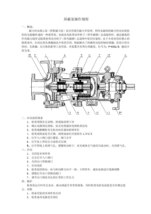
屏蔽泵操作规程一、概述:磁力传动离心泵(简称磁力泵)是应用现代磁力学原理,利用永磁体的磁力传动实现扭矩的无接触传递的一种新型泵,也就是电机带动外转子(即外磁钢)总成旋转时,通过磁场的作用磁力线穿过隔离套带动内转子(即内磁钢)总成和叶轮同步旋转,由于介质封闭在静止的隔离套内,从而达到无泄漏抽送介质的目的,彻底解决了机械传动泵的轴封泄漏,而设计的全密封、无泄漏、无污染的新型工业用泵。
本装置共有两台屏蔽泵,位号为:P-605A/B,输送介质为苯。
二、启动前的准备1、检查周围有无杂物,将现场清理干净2、确认电源到达现场,如无电则通知电修检查送电3、检查地脚螺栓有无松动如有通知检修单位4、检查润滑油是否正确,润滑油油位应保持在1/2-2/35、打开入口阀门进行灌泵,阀门全开6、打开泵上所有压力表的引压阀7、打开管线上的排气孔,缓慢转动转子,直至液体无气泡均匀流动时,关闭排气孔。
三、启动1、关闭泵本体伴热2、完全打开入口阀门3、关闭出口管路阀门4、启动电机5、检查泵的转向,如与转向牌方向不一致,立即停车,通知电修进行线路调整6、缓慢打开出口管路的阀门7、调节出口阀直至达到正常的工作压力四、维护检查泵运行时有无杂音、振动或温升异常的现象,同时检查电机电流值是否在额定值五、切换1、将备用泵的本体伴热关闭2、检查备用电源是否到位3、检查地脚螺栓有无松动现象4、对备用泵进行排气。
5、启动电机6、缓慢打开备用泵出口管路的阀门,同时慢慢关闭切换泵的出口阀,待备用泵压力稳定后,关闭切换泵的出口阀7、关闭切换泵的电源8、打开切换泵的本体伴热9、调节备用泵出口阀直至达到正常的工作压力六、停车1、关闭电机2、打开泵本体伴热。
3、长时间放置时,应对泵进行冲洗备用,并关闭本体伴热。
七、常见故障、原因及解决方法。
水泵md说明书

md型煤矿用耐磨多级离心泵安装使用说明书安全警示※使用本产品之前必须认真阅读本产品使用说明书及相关配套产品的使用说明书。
在安装、使用和维修过程中,必须遵守本产品及其相关设备的安全操作规程。
※泵不得长时间在小流量或零流量下运转。
否则会引起泵机组振动甚至抽送液体汽化,造成人身伤害和设备的损坏。
※泵为旋转设备,在安装、维修泵机组前必须切断电源,否则会造成人身伤害。
※泵在使用前必须检查电缆线有无破损、折断以及接地是否良好,泵机组运行时,严禁手进入或拆下防护罩,否则会造成人身伤害。
※泵在使用前,请先接通电源,“点启动开关按钮”确定旋转方向正确无误后,方可使用。
※对煤矿井下配用电机,yb2系列电机可用于井下,但不能用于采掘工作面,用于采掘工作面必须配用ybk系列电机,y系列电机不能用于井下。
※必须安装联轴器防护罩,以防发生人身伤亡事故。
※为防止泵运转后,因泵轴与电机轴相抵出现断轴甚至烧电机事故,因而在调整泵、电机两个联轴器的间隙前,必须先将泵轴向联轴器方向最大限度的外拉,然后在按说明书要求进行间隙调整。
※用户与本企业均不得随意变更安标配套件及零(元)部件配置。
目录一、概述 ???????????????????(4)二、结构特征与工作原理 ????????????(4)三、技术特性 ?????????????????(8)四、外形及安装尺寸 ??????????????(15)五、水泵的安装与调试 ?????????????(19)六、水泵的使用、操作 ?????????????(20)七、故障分析与排除 ??????????????(21)八、保养、维修 ???????????????? (22)九、运输、贮存 ???????????????? (23)十、开箱及检查???????????????? (23)十一、安标受控零部件明细表???????????(23)十二、易损件明细表???????????????(24)十三、成套供应明细表??????????????(25)一、概述1、 md 型煤矿用耐磨多级离心泵,是我厂在引进、消化、吸收先进技术基础上研制开发成功的,该产品不仅效率高、汽蚀性能好、关键是运行平稳可靠。
磁力泵安全操作规程

磁力泵安全操作规程磁力泵是一种特殊的泵类设备,具有复杂的结构和高度的技术要求,所以在操作时必须遵守严格的安全规程,以保证人员和设备的安全。
以下是磁力泵的安全操作规程,希望能对大家有所帮助。
一、操作前准备阶段:1. 操作人员必须穿着合适的工作服和个人防护装备,如安全帽、防护眼镜、防护手套等。
2. 在操作前,必须仔细学习磁力泵的使用说明书和操作规程,了解泵的结构、工作原理和安全注意事项。
3. 检查泵的外部情况,确认泵是否有明显损坏或泄漏现象。
如有异常情况,必须及时报告上级或维修人员。
4. 检查泵的进出口阀门是否处于关闭状态,以防止液体外泄。
5. 检查电源是否正常,并确保电源接地良好。
二、启动和操作阶段:1. 操作人员必须了解磁力泵的启动和停止程序,不得随意操作。
2. 操作人员必须按照正确的操作顺序和步骤启动泵,如先开启进口阀门再启动泵,在泵完全停止后再关闭出口阀门。
3. 在启动泵之前,必须确保泵内没有异物,并检查各种部件连接是否牢固。
4. 在启动泵后,要仔细观察泵的运行情况,包括转速、温度、压力等参数是否在正常范围内。
5. 在操作过程中,不得随意触摸泵的旋转部件,以免发生危险。
6. 在停止泵之前,必须先关闭进出口阀门,并等待泵完全停止后再断开电源。
7. 在操作过程中,严禁随意调节泵的工作参数,如转速、流量等,必要时需经过授权人员才能进行调整。
三、维护和检修阶段:1. 在进行维护和检修之前,必须先停止泵的运行,并切断电源。
2. 维护和检修必须由专业人员进行,不得擅自进行操作。
3. 在拆卸泵零部件时,要注意安全操作,使用适当的工具,并确保安全防护措施做好,防止意外伤害的发生。
4. 在更换密封件时,要仔细检查密封件的质量,避免因密封失效导致泵的安全隐患。
5. 在维护和检修完毕后,必须进行试运行,确保泵的工作正常。
总结:磁力泵的安全操作规程是保证人员和设备安全的重要措施,操作人员必须严格遵守规程,增强安全意识,做到安全第一。
磁力驱动泵操作规程

磁力驱动泵操作规程1范围1.1本标准规定了动力分场废水处理站MX系列易威奇磁力驱动泵(氢氧化钙加药泵、氢氧化钠加药泵)操作的技术条件和要求。
1.2本标准适用于平安高精铝业有限公司动力分场废水处理站MX 系列易威奇磁力驱动泵(氢氧化钙加药泵、氢氧化钠加药泵)的操作。
2 内容2.1 安装切断电源当有人在对泵进行工作时,要特别注意,以免其它的操作员由于失误打开供电开关,在噪音大或者光线差的环境,在供电开关旁要放置一个标志,以告知其他人有人正在对泵进行维修中。
禁止抓握塑料部件移送泵移送泵时严禁抓握塑料部件,如:前壳、法兰或底座。
否则,塑料部件会损坏,导致泵坠落,引起人身伤害。
泵的最大重量约为20公斤。
移送泵时请保持底座向下,水平移送。
电工作业进行电工操作时,应由专业人员进行。
否则会造成人身伤害或泵的损坏。
2.1.1 安装位置应该尽可能地安装在贮罐的近处,并且要比贮罐低(自流进液)。
如果泵安装在高于贮罐中液面的位置(吸人式)时,则须在灌液管路和吸人管上安装底阀。
泵的扬程取决于液体的性质、温度和吸入管的长度。
2.1.2 在室内和室外使用泵可在室内和室外使用。
但是要采取安全措施,以避免电机和配电器暴露在流体或其它的自然灾害中。
2.1.3 安装位置要选择平坦的且不会被其它机器引起振动的地点作为安装位置。
考虑进行维修时需要留有足够的空间。
2.2 接管下表是泵、管路和法兰连接的螺栓大小和上紧力矩。
请遵照螺栓大小和上紧力矩进行安装。
(下表数据是指金属法兰和橡胶垫片)型号螺栓大小上紧力矩(N·m)MX-250,251,400,401,402,403M16202.2.1吸入管路吸入管路应尽可能的采用自流进液。
管路应尽可能短且弯曲最少。
在吸人管路上安装类似膨胀节及支撑件使管路的重量和温度应力不能直接作用到泵上。
小心接好吸人管上的接头,不要使空气被吸进。
吸入管中有空气将会使泵损坏。
如果吸人部分不合理(例如:吸人罐真空、吸人扬程过大、或者吸人管过长等),将会出现NPSHa lt; NPSHr +0.5cm 的情况产生汽蚀。
- 1、下载文档前请自行甄别文档内容的完整性,平台不提供额外的编辑、内容补充、找答案等附加服务。
- 2、"仅部分预览"的文档,不可在线预览部分如存在完整性等问题,可反馈申请退款(可完整预览的文档不适用该条件!)。
- 3、如文档侵犯您的权益,请联系客服反馈,我们会尽快为您处理(人工客服工作时间:9:00-18:30)。
IWAKI AMERICA MAGNETIC DRIVE PUMP MD/WMD SERIESContents1SAFETY INSTRUCTION (1)2UNPACKING AND INSPECTION (3)3OPERATING PRINCIPLE (3)4MODEL IDENTIFICATION GUIDE (4)5SPECIFICATIONS (5)Construction/Materials (6)6HANDLING INSTRUCTIONS (7)7INSTALLATION, PIPING, AND WIRING (8)7.1Installation (8)7.2 Piping instructions (9)7.3Wiring (9)8 ASSEMBLY (11)9OPERATION (12)10 MAINTENANCE/INSPECTION AND CONSUMABLE PARTS (14)11 PARTS DESCRIPTION AND EXPLODED VIEW (14)12 DIMENSIONS (15)13 TROUBLESHOOTING (16)P/N 180243 Rev. C Jan 20101 SAFETYINSTRUCTIONSTurn off the power supplyWorking without disconnecting the power supply may cause an electrical shock. Before performing any assembly or maintenance procedures involving the pump, make sure to turn the power supply switch off and to stop the pump and other related devices.Terminate operationWhen you detect any signs of abnormal operation, terminate pump operation immediately.For specified application onlyThe use of a pump in any applications other than those clearly specified may result in injury or damage to the pump. Use the pump strictly in accordance with the pump specifications and application capabilities.ModificationNever modify the pump. Iwaki America will not be responsible for any accident or damage of any kind caused by the user remodeling the pump without first obtaining permission or instructions from Iwaki America.Protective clothingIf application involves the handling of hazardous liquids, protective gear (gloves, glasses, clothing, etc) must be worn before performing any maintenance on the pump. Please follow safety guidelines established for such applications.OperationOperation of the pump and related system must be by experienced or knowledgeable personal. The pump operator or pump operation supervisor must not allow any personal who have little or no knowledge of the pump to operate the unit.PowerDo not operate the pump at a different voltage than specified on the nameplate. This may result in damage to the unit or fire. Only the specified voltage must be used.Do not submergeIf the motor or power cable becomes wet or damp fire or electric shock may occur. The unit should be installed in such a manner to prevent contact with fluids or in a wet environment. Follow all local, state and government regulations for the installation and wiring of the pump.Spill accidentProtective measures should be taken against any accidental spill or leakage of any hazardous liquids as a result of unexpected damage to the pump or the related piping. Please follow safety guidelines established for such occurrences.Operating site must be free of water and humidityThe pump is not designed to be water-proof or dust-proof. The use of the pump in places with splashing water or humidity above 90% may result in an electrical shock or short circuit.Do not damage power cordDo not cut, abrade or forcibly pull the power cord. Excessive heat or heavy load applied to the cable may damage the cable and finally result in a fire or an electrical shock.Do not cover the motorCovering the motor during operation may result in an accumulation heat inside the motor and cause a fire or a mechanical failure. Proper ventilation is necessary for the motor.GroundingDo not operate the pump without proper grounding; otherwise an electrical shock may result. Follow all local, state and government regulations for the installation and wiring of the pump.Power cord cannot be replacedNever use a damaged power cable; otherwise, a fire or an electrical shock may result. Handle the power cord carefully, as it cannot to be replaced by a new cable. (The complete motor must be replaced if damaged).Location and storageDo not install or store the pump in the following places:* Places where a flammable gas or material is used or stored.* Places where the ambient temperature is extremely high (104°F or higher) or extremely low(32°F or lower).Static Electricity HazardWhen low electric conductivity liquid such as ultra-pure water is handled, static electricity may be generated in the pump, which may cause static discharge and damage the pump. Take appropriate countermeasures to avoid and remove any potential static electricity.2 UNPACKING AND INSPECTIONOpen the package and check that the productconforms to your order. Also, check each of thefollowing points. For any problem orinconsistency, contact your distributor at once.1. Check that the model number indicated on thenameplate conforms to the specifications ofyour order.2. Check that all the accessories you ordered areincluded.3. Check that the pump body and parts have notbeen accidentally damaged or that any boltshave not been loosened in transit.3 OPERATINGPRINCIPLEA sealless magnet drive pump uses magnet torque to transmit energy from the motor to the impeller. A magnet coupling is formed using an inner, or driven magnet, attached to the impeller and an outer, or drive magnet, attached to the motor shaft. This design eliminates mechanical shaft seals or packing, since there is no direct connection between the motor shaft and the impeller. The front and rear casings, sealed with a static o-ring, form the pump or liquid end. The magnetic field is transmitted from the drive magnet through the rear casing to the driven magnet that is attached to the impeller. The combined coupling torque of the drive magnet and impeller magnet provides the driving power to theDrive MagnetDriven Magnet4 MODELGUIDEIDENTIFICATION1 2 3 4 5 6 7 81. Series name (WMD specifies US motor design)2. Pump Size (6, 10, 15, 20, 30, 55, 70, 100)3. R = Rotating Spindle (omit for MD-6 and MD-10)4. L = UL Listed Motor, included in 6, 10, 55, 70, 100 115V model(also on older 15/20/30/40 models)5. Pump typeBlank: Standard ImpellerZ: High Head ImpellerX: High Flow Impeller6. Suction/Discharge Port ConnectionsBlank: Hose ConnectionT: Threaded Connection7. Power source voltage:115: 115V (50.60Hz) 230: 230V (50/60Hz)220:220/240V(50/60Hz)8. NL = UL Listed 115V Motor (applies to 15, 20, 30, 40 sizes)5 SPECIFICATIONSConnections ModelHose NPT MotorOutput (HP) MotorSpeed(RPM)Current(Amps)MaxFlow(GPM)MaxHead(Ft)Max Sys.Pressure(PSI)SpecificGravityWeight(Lbs)PolypropyleneMD-6 1/2---1/25031000.252.3 4.5 2.80 1.2 1.8MD-10 1/2---1/12529000.403.1 6.84.30 1.1 1.6MD-15R(T) 1/21/21/7531000.29 5.0 11.1 7.20 1.3 3.5 WMD-15R(T) 1/21/21/38 3100 0.82 5.0 11.1 7.20 1.3 6.0MD-20RT(T) 5/83/41/38 3100 0.48 8.2 14.1 9.95 1.1 4.4 WMD-20R(T) 5/83/41/38 3100 0.48 8.2 14.1 9.95 1.1 7.0MD-20RX(T) 1 1 1/38 3100 0.50 13.7 8.2 5.69 1.3 4.4 WMD-20RX 111/3831000.5013.7 8.2 5.69 1.3 7.0MD-20RZ 5/83/41/3831000.53 2.9 22.6 14.22 1.1 4.4 WMD-20RZ 5/83/41/383100 0.53 2.9 22.6 14.22 1.1 7.0MD-30R 3/43/41/1631500.80 10.0 17.7 11.60 1.3 7.7 WMD-30R 3/43/41/1631501.00 10.0 17.7 11.60 1.3 9.0MD-30RX 1 1 1/16 3150 1.10 19.0 13.5 8.54 1.1 7.7 WMD-30RX 111/1631501.0019.0 13.5 8.54 1.1 9.0MD-30RZ 5/83/41/1631501.10 4.5 36.1 24.18 1.0 7.7 WMD-30RZ 5/83/41/163150 1.00 4.5 36.1 24.20 1.0 9.0MD-40R 3/43/41/1232001.30 13.7 21.3 14.22 1.1 8.6 WMD-40R 3/43/41/1232001.90 13.7 21.3 14.22 1.1 10.0MD-40RX 1 1 1/12 3200 1.20 22.4 15.4 9.95 1.1 8.6 WMD-40RX 111/1232001.9022.4 15.4 9.95 1.1 10.0MD-55R 1 1 1/8 3400 1.60 18.4 26.9 17.06 1.2 10.1MD-70R 1 1 1/4 3400 2.80 25.6 31.8 21.33 1.0 13.2MD-70RZ 3/43/42/734003.80 11.4 66.6 42.70 1.0 13.2MD-100R 1 1 1/3 3300 3.40 35.6 39.0 25.60 1.2 18.7 WMD-100R 1 1 1/3 3400 * 35.6 39.0 25.60 1.2 * FluoroplasticWMD-30FX ---1/21/163200 0.9 3.2 35.2 17.01.3(1.5)9 WMD-30FY ---1/21/163200 0.9 3.2 26.0 17.01.5(1.8)9 WMD-30FZ ---1/21/163200 0.9 2.6 24.0 21.3 1.9(2.1) 9MD-55Y ---11/833001.917.125.621.31.3(1.5)11.9 MD-55Z ---11/833001.613.0 19.0 21.3 2.0(2.2) 11.9 WMD-100FY --- 1 1/3 3450 * 36.0 38.0 31.2 1.3(1.6) *MD-100FY ---11/333003.435.737.731.21.3(1.6)18.7 WMD-100FZ ---1 1/3 3450 * 28.0 27.2 31.2 1.9(2.2) *MD-100FZ ---11/333003.428.027.231.21.9(2.2)18.7 Notes:1. Pump performance data is based on pumping clean water at ambient temperature.2. The maximum flow rate is at 0 discharge head.3. Maximum viscosity of liquid: 1.0 cP (for a specific gravity of 1.0)4. Permissible liquid temperature: 32-176°F (0 – 80°C). Note, permissible temperature range may differ dependingupon the type of liquid and operating conditions.)5. The maximum specific gravity of the liquid is the value at max. flow rate. The value varies depending on the flowrate, ambient temperature, viscosity of liquid, etc.6. Motor: Single-phase capacitor-run induction motor or 3-phase induction motor.* Built-in thermal protectorA thermal protector is built in the motor. The protector automatically stops motor operation when the motor isoverheated. (The motor starts again when the temperature falls to normal.)Typical Construction/MaterialsName Qty MaterialNo. PartGFRPP (Note 1)1 FrontCasing 1Casing 12 Rear3 Impeller 1Ceramic4 Thrust 2 Alumina5 O-ring 1 FKM or EPDM (Note 2)6 Screw 4~6 Stainless steelcontaining7 Bearing 2 Fluororesinfiller material (Note 3)ceramic8 Spindle 1 Alumina9 Motor 1Note 1: The material of the impeller used in MD-70RZ, 100R, 100R-5 is CFRPP.Note 2: More elastomer options availableNote 3: The material of the bearing used in (W)MD-20RZ, 30RZ, and MD-70RZ is PPS.6 HANDLINGINSTRUCTIONS1. Handle the pump carefullyStrong impact to the pump assembly may result in damage or reduced performance.2. StartingBefore priming the pump be sure the power is turned off then proceed with filling the pumpend with water. Note, the pump must be fully primed before starting.Next close the valve on the outlet or discharge side of pump. Turn on power to the pump,when full speed is reached gradually open the discharge vale until specified flow rate isachieved.CautionOperating the pump dry (without liquid) may cause severe damage.3. StoppingWhen stopping the pump, first close the discharge valve gradually. When it is completelyclosed, turn off the power switch so that the pump stops. Never stop the pump suddenly byquickly closing a valve (i.e., solenoid or hydraulic valves).CautionQuick valve closure may cause water hammer that can cause severe damage to thepump.4. TemperatureThe pump itself may not suffer a change in performance due to temperature fluctuation.However, the liquid may change in terms of viscosity, vapor pressure, and corrosive properties.Pay special attention to changes in liquid characteristics as a result of temperature fluctuation.Liquid temperature range: 32 – 176°F (0 – 80°C)Ambient temperature range: 32 – 104°F (0 – 40°C)5. As there is a powerful magnet inside the pump unit, do not use any liquid that contains metallicsubstances such as iron, nickel, etc.6. Do not operate the pump in the following places:∙ Places exposed to rain and/or wind.∙ Places where the temperature falls below 32°F (0°C).∙ Places where corrosive gas (such as chlorine) is present.∙ Places exposed to splashing of water or fluid being pumped.∙ Places where the ambient temperature is 104°F (40°C) or above.∙ Places where explosive or combustible materials/gases are present.7. Do not operate the pump with the following liquids:∙ For the compatibility to chemical liquid or any special liquid, contact an Iwaki America sales representative.∙ Liquids that significantly swell polypropylene.∙ Paraffinic hydrocarbons such as gasoline and kerosene.∙ Halogenated hydrocarbons such as trichloroethylene and carbon tetrachloride.∙ Ether and low-grade ester∙ Slurry(For a chemical compatibility to guide contact Iwaki America customer service.)8. To prevent fire and explosions, do not place dangerous or flammable substances near thepump.9. Be sure unit is properly ground.10. If a pumped is damaged, it can be dangerous to operate. Contact factory for assistance.11. Avoid direct physical contact with the motor or pump during operation, as surface temperaturesmay be extremely high due to operating conditions.7 INSTALLATION, WIRING AND CONNECTIONS7.1 Installation1. Installation siteInstallation site must have an ambient temperature of 32-104°F (0-40°C) and a relativehumidity lower than 90%. Install the pump where maintenance and inspection work can bedone easily.2. Pump installation methodThis pump is not self-priming. It is recommended that the pump shall be installed in aposition lower than the liquid level of the suction tank by at least 12 inches (30 cm). If thisdistance is too short, air may enter the pump, causing damage.3. Direction of pump discharge portThe discharge port can be directed as desired. However, for efficient elimination of air inthe pump end, it is recommended that the discharge port be positioned in the horizontaldirection.4. Anchoring of baseThe base of the pump must be anchored firmly. The pump must not be mounted in avertical position.7.2 Piping instructions1. To minimize frictional resistance, the shortest piping possible with a minimum number ofbends should be utilized on the inlet or suction side of the pump.2. Use a corrosion-resistant vinyl hose that is rated at or above the pressure rating of thepump (see specification table).3. Hose size (for hose-barb style pumps)Select hose size in accordance with the diameter of the pump connections. As the hosetends to be crushed under the force, the use of a braided reinforced hose is recommended.Note, if the connection on the suction side is loose air may be mixed in with pumped fluid.(In the case of high temperature liquids, special attention must be paid to the selectionof a hose.)4. Hose connectionBe sure to cut the ends of the hose straight. Press the hose end firmly against the dischargeor suction port until it reaches the bottom of the port. Use a fastener (such as a hose clamp)to make the connection tight and leak free.CautionDo not over tighten the connection ports (suction and discharge) excessively asthey are made of plastic resin and are could be damaged.5. Valve installationInstall valves close to the suction and discharge ports.∙ Suction side valve:For easy liquid removal and pump maintenance∙ Discharge side valve:For adjustment of the discharge rate or head and for easy removal and pumpmaintenance.7.3 Wiring1. Prior to wiring the pump, confirm the voltage indicated on the nameplate is correct foryour installation. (Observe all local and national regulations regarding electrical work.)The connection diagram is presented on the next page.2. The pump does not have an external switch. It starts when power is supplied to the pumpwires.Wiring diagrams• (W)MD-15R, 20R, 20RX, 20RZ, 30R, 30RX and 30RZ (Single-phase capacitor run motor withthermal protector)• (W)MD-40R, 40RX, 40RZ, 55R, 70R, 70RZ, and 100R (Single-phase capacitor run motor withthermal protector)• MD-70R, 70RZ, and 100R models (3-phase motor, 220/380V)• (W)MD-70R, 70RZ, and 100R models (3-phase motor,400/440V)8 ASSEMBLY1. Place the motor on end vertically so that the shaft is pointed upward.2. Install the drive magnet on the motor shaft and position the shaft flush with the inside of themagnet. Note: On WMD models, screw the bracket to the motor first.3. Insert the rear casing into the magnet/motor bracket.4. Install the impeller and O-ring into the rear casing.5. Place the front casing over the pump, making sure that the volute casing is aligned.6. Using a hex head driver, fasten the liquid end to the bracket using six screws. Tighten in a starpattern.9 OPERATIONCaution• Before operating the pump, confirm that connections to the discharge and suction ports are secure.• Dry run operation (operation without liquid in the pump) damages the pump. Be sure to fill the pump with liquid prior to startup.• Do not operate the pump with closed, or almost entirely closed, suction and/or discharge side valve(s). A closed suction valve will cause dry-run operation.•Do not open or close the suction or discharge side valve suddenly, this may result indecoupling and damage to the pump end. (Under such circumstances, turn off the power supply immediately. When the motor stops rotating, the magnetic coupling will be reconnect automatically.)No. Operation StepNote1 Check piping, wiringand voltage. Check connections to confirm they are secure and leak-free. Check the power supply voltage by referring to the information on the nameplate.2Open and close valves. Fully open suction side valve. Fully close discharge side valve.3 Check that pumpchamber is filled with liquid. Fill pump chamber with priming liquid.Be sure suction line is completely filled, this is especially important if pump is above liquid level.4 Supply power topumpAfter steps 1 to 3 above, connect power supply to start pump.5 Adjust dischargecapacity & head to desired values.Adjust discharge side valve gradually till desired discharge capacity and head are obtained. Do not open or close valves suddenly.Note: Do not keep discharge side valve closed for more than 1 minute.Note: Check that pump is operating normally. If not, turn off power immediately and eliminate cause referring to 'Causes of Trouble and Troubleshooting' section (p.27).6 Checkpoints during operation Be careful to prevent solids from entering the pump. Solids in thepump may cause impeller to be locked stopping liquid circulation. The motor continues to rotate even if impeller is locked. In such acase, turn off power supply at once.Pump Stopping ProcedureStep Description No. Stopping1 Close discharge side valve. Close discharge side valve gradually.Do not use electromagnetic valve for quick closing.2 Switch power off. Check that motor stops smoothly after power supply isdisconnected. If not, pump should be inspected. (For details,contact Iwaki or your dealer.)How to store pump when it is out of use for a long timeRemove the liquid from the pump if it is to be stored for a long period of time. In addition, run it with water for about 5 minutes every 3 months to prevent rust on the motor bearing.Warning• Before draining the pump, turn off the power supply.• Be sure to wear proper safety gear (gloves, protective shoes, etc.) when handling pump end for draining purposes, especially when a hazardous chemical is being pumped.CautionNote that residual liquid may run from the discharge and suction ports when the housing isremoved. Do not allow any electric parts to come in contact with the liquid.Never discharge hazardous or chemical liquid over the ground or floor in the plant. Instead, use a draining pan (or container). Observe each applicable local law or regulation for the handling or disposal of hazardous liquids.Draining procedure1. Turn off the power supply. (Make sure no other operator will turn the power supply onaccidentally.)2. Close the discharge and suction sides valves fully.3. Remove the hoses piping attached to the pump.4. Remove the screws on the pump base to detach the pump from its mounting location.5. Rotate the pump.6. Discharge hazardous liquids appropriately.10 MAINTENANCE/INSPECTIONMaintenance and inspection• When the pump has been used for a long time, the front casing screws attaching the pump headto the motor bracket may loosen. Tighten screws periodically taking care not to deform the plastic parts. Also, after pump has been stored for a long time, tighten screws before pump is used again.• Daily inspectionCheck operating conditions (vibration, noise) as well as electric current value and pump discharge capacity. As soon as you find any abnormality, turn off power and refer to “Troubleshooting” on page 27.11 PARTS DESCRIPTION AND EXPLODED VIEWItem No. Description Item No. Description 1 Screw 5 Rear Casing 2Front Casing 6 Drive Magnet 3 O-Ring 7 Motor Assembly 8Retainer(MD-100R,100F,55F only)4Impeller9 BracketTYPICAL MD-6 through 40 TYPICAL MD-55/70/10012 DIMENSIONSDimensions in inches*Varies with motorConnectionsW H L a b c d e fNPT(M)Model HosePolypropylene Models (MD-115V models only)MD-6/10 1/2 --- 2.91 3.62 4.09 1.18 2.87 2.36 1.77 1.22 0.67WMD-15R(T) 1/2 1/2 3.50 4.26 9.46 2.37 4.15 2.50 1.94 1.52 0.85MD-15R(T) 1/2 1/2 3.74 4.39 7.05 1.97 4.59 3.35 2.17 1.52 0.85WMD-20R(T) 5/8 3/4 3.50 4.35 9.70 2.37 4.39 2.50 1.94 1.30 1.12MD-20R(T) 5/8 3/4 4.17 4.19 7.99 1.73 4.06 3.54 1.77 1.30 1.12WMD-20RX(T) 1 1 3.50 4.95 10.37 2.37 5.06 2.50 1.94 1.83 40+MD-20RX 1 1 4.17 4.75 8.66 1.73 4.45 3.54 1.74 1.83 40+WMD-20RZ 5/8 3/4 3.50 4.70 9.98 2.37 4.67 2.50 1.94 1.56 1.52MD-20RZ 5/8 3/4 4.17 4.92 8.31 1.73 4.17 3.54 2.17 1.56 1.52WMD-30R 3/4 3/4 3.50 4.70 11.65 2.37 5.72 2.50 1.94 1.89 1.22MD-30R 3/4 3/4 4.72 5.12 9.76 1.57 5.87 3.94 2.36 1.89 1.22WMD-30RX 1 1 3.50 5.09 11.89 2.37 5.96 2.50 1.94 1.97 40+MD-30RX 1 1 4.72 5.51 10.00 1.57 6.10 3.94 2.36 1.97 40+WMD-30RZ 5/8 3/4 3.50 4.70 10.97 2.37 5.04 2.50 1.94 1.56 1.53MD-30RZ 5/8 3/4 4.72 5.12 9.05 1.57 5.16 3.94 2.36 1.56 1.53WMD-40R 3/4 3/4 4.38 4.84 11.34 3.09 6.66 3.37 2.08 1.89 1.22MD-40R 3/4 3/4 4.72 5.12 9.85 1.57 5.87 3.94 2.36 1.89 1.22WMD-40RX 1 1 4.38 5.23 11.30 3.09 7.02 3.37 2.08 1.97 43+MD-40RX 1 1 4.72 5.51 10.08 1.57 6.10 3.94 2.36 1.97 43+MD-55R 1 1 4.72 6.10 10.77 1.57 7.05 3.94 2.56 2.42 1.57MD-70R 1 1 5.63 6.11 10.18 2.76 5.71 4.25 2.56 2.07 1.70MD-70RZ 3/4 3/4 5.63 6.50 9.72 2.76 5.24 4.25 2.56 1.65 1.87MD-100R 1 1 6.14 6.89 12.67 2.76 6.38 4.33 2.95 2.55 1.714.8710.432.551.713.503.00*WMD-100R 117.44*Fluoroplastic Models (MD-115V models only)(X,Y,Z) --- 1/2 3.50 5.02 11.82 2.37 6.67 2.62 2.29 1.84 1.22WMD-30FMD-30F(X,Y,Z) --- 1/2 4.72 5.12 9.09 1.57 6.77 3.94 2.36 1.53 1.52(Y,Z) --- 1 4.72 6.11 10.53 1.57 6.61 3.94 2.56 2.30 1.56MD-55FWMD-100F (Y,Z) --- 1 * 6.80 * 3.00 12.05 4.88 3.56 2.55 1.71MD-100 (Y,Z) --- 1 6.14 6.89 12.67 2.76 6.38 4.33 2.95 2.55 1.7113 TROUBLESHOOTINGPump does not start. Pump isnot pumpingor flow isinsufficient.Electriccurrentis high.Excessivenoise orvibration.Liquidleaks.Power is not supplied or wiringis faulty. ○○Check powerconnections orcontact your dealer. Motor is out of order (shortcoil or capacitor failure).○○Contact your dealer.There is residual air in the pump. ○○Eliminate air frompump end completely.Air is sucked in via suction port. ○○Check suctionconnection.Pump is running dry. ○○Supply priming waterto pump.Specific gravity/viscosity ofliquid is too high. ○○○Confirm applicationwith pumpspecifications. Periphery of impeller magnet isin contact with rear casing. ○○○○Contact your dealer. Impeller is damaged. ○○○○Contact your dealer.Foreign matter is stuck toimpeller. ○○○Contact your dealer. O-ring is damaged. ○Contact your dealer. Loose front casing bolts. ○○Tighten bolts.5 BOYNTON ROAD HOPPING BROOK PARK HOLLISTON, MA 01746 USATEL: 508-429-1440 FAX: 508-429-1386 。