FPGA门容量计算方法 xilinx
fpga 数学运算
fpga 数学运算FPGA数学运算:从基本概念到实践应用引言:FPGA(现场可编程门阵列)是一种硬件器件,其在数字电路设计和应用领域中具有广泛的应用。
数学运算是FPGA设计中的一项基本任务,其在信号处理、图像处理、加密解密等领域中发挥着重要作用。
本文将从基本概念开始,一步一步回答关于FPGA数学运算的问题,为读者提供相关知识。
第一部分:FPGA概述FPGA是一种可重新配置的硬件器件,其内部包含了大量的可编程逻辑单元(PL)和存储单元(BRAM)。
PL和BRAM可以根据特定设计的需要进行定制,因此FPGA具有高度的灵活性和可变性。
这种可变性使得FPGA 可以被用于各种数学运算的实现。
第二部分:FPGA数学运算基础知识2.1 数制系统FPGA中常用的数制系统有二进制、十进制和十六进制。
在数学运算中,我们通常使用十进制进行计算,因为十进制可以直接和人类的思维方式对应。
当然,对于一些特定的应用场景,如图像处理等,我们可能会使用二进制或十六进制。
2.2 逻辑运算逻辑运算是FPGA数学运算的基础。
逻辑运算包括与、或、非等基本运算。
FPGA中的逻辑运算可以通过逻辑门电路的配置来实现。
例如,AND门可以将两个输入信号的逻辑与运算输出结果。
2.3 算术运算算术运算是数学运算的重要内容之一,包括加法、减法、乘法和除法等基本运算。
FPGA中的算术运算可以通过加法器、减法器、乘法器和除法器来实现。
这些运算器件可以使用FPGA内部的PL和BRAM来实现相关的电路功能。
2.4 浮点运算浮点数运算也是FPGA数学运算的重要内容。
浮点数运算主要涉及到浮点数的表示和浮点数的运算规则。
在FPGA中,我们可以使用浮点数处理器来实现浮点数的运算。
这些处理器是由FPGA内部的PL和BRAM来构建的。
第三部分:FPGA数学运算的实践应用3.1 信号处理信号处理是FPGA数学运算的重要应用之一。
FPGA可以用于实现数字滤波器、快速傅里叶变换(FFT)等信号处理算法。
fpga消耗的片上存储资源计算公式

FPGA(Field-Programmable Gate Array)是一种集成电路,其片上存储资源是指可在其内部进行逻辑操作的存储单元。
在FPGA设计中,计算FPGA消耗的片上存储资源是至关重要的,可以帮助设计者评估和优化FPGA的设计。
本文将介绍FPGA消耗的片上存储资源的计算公式,以帮助读者深入了解FPGA设计中的重要指标。
一、FPGA消耗的片上存储资源1.片上存储资源的定义FPGA的片上存储资源是指可供存储数据和逻辑操作的资源,常见的包括寄存器、片上存储器和分布式RAM等。
这些存储资源在FPGA的逻辑元件中起着至关重要的作用,直接影响着FPGA的性能和功能。
2.片上存储资源的消耗在FPGA设计中,各种逻辑元件和数据通路需要占用片上存储资源。
计算FPGA消耗的片上存储资源是设计过程中必不可少的一环。
有效地计算FPGA消耗的片上存储资源可以帮助设计者合理规划FPGA的资源利用,从而达到最佳性能。
二、计算FPGA消耗的片上存储资源的公式3.寄存器的消耗计算FPGA中的寄存器一般用于保存临时数据和中间结果,是FPGA逻辑操作的重要组成部分。
计算寄存器的消耗一般采用以下公式:寄存器消耗 = 寄存器个数× 逻辑元件的布局其中,逻辑元件的布局是指FPGA设计中各个逻辑元件的布局情况,根据具体情况进行调整。
4.片上存储器的消耗计算片上存储器是FPGA设计中常用的存储资源,计算片上存储器的消耗一般采用以下公式:片上存储器消耗 = 存储器个数× 存储器的布局不同类型的存储器在FPGA设计中有不同的布局方式,因此在计算片上存储器的消耗时需要根据具体情况进行调整。
5.分布式RAM的消耗计算分布式RAM是FPGA中的一种特殊存储资源,可用于存储逻辑操作的中间结果。
计算分布式RAM的消耗一般采用以下公式:分布式RAM消耗 = RAM个数× 每个RAM的大小在FPGA设计中,分布式RAM的大小通常根据实际需求进行调整,因此在计算分布式RAM的消耗时需要根据具体情况进行灵活处理。
fpGa_CPLD设计工具xilinxISE使用详解
1.第一章:FPGA/CPLD简介●FPGA一般是基于SRAM工艺的,其基于可编程逻辑单元通常是由查找表(LUT,look up table)和寄存器(register)组成。
其中内部的查找表通常是4输入的,查找表一般完成纯组合逻辑功能;●Xilinx可编程逻辑单元叫做slice,它由上下两部分组成,每部分都由一个register加上一个LUT组成,被称为LC(logic cell,逻辑单元),两个LC之间有一些共用逻辑,可以完成LC之间的配合工作与级连;●Altera可编程逻辑单元叫做LE(Logic Element,逻辑单元),由一个register加上一个LUT构成;Lattice的底层逻辑单元叫做PFU(programmable Function unit,可编程功能单元),它由8个LUT和9个register组成。
●Ram和dpram/spram/伪双口RAM,CAM(content addressable memory)。
Fpga中其实没有专业的rom硬件资源,实现ROM是对RAM赋初置,并且保存此初值●CAM,即内容地址储存器,在其每个存储单元都包含了一个内嵌的比较逻辑,写入cam的数据会和其内部存储的每一个数据进行比较,并返回与端口数据相同的所以内部数据的地址。
总结:RAM是一种根据地址读/写数据的存储单元;而CAM 和RAM恰恰相反,它返回的是与端口数据相匹配的内部地址。
使用很广,比如路由器中的地址交换表等等●Xilinx块ram大小是4kbit和18kbit两种结构。
Lattice块ram是9kbit●分布式ram适合用于多块小容量的ram的设计;●Dll(delay-locked loop)延迟锁定回环或者pll(phase locked loop)锁相环,可以用以完成时钟的高精度,地抖动的倍频/分频/占空比调整/移相等功能。
Xilinx主要集成的是DLL,叫做CLKDLL,在高端的FPGA中,CLKDLL的增强型模块为DCM (digital clock manager,数字时钟管理模块)。
xilinx luts和gate count换算 -回复
xilinx luts和gate count换算-回复Xilinx LUTs (Look-Up Tables)和Gate Count (门数)是数字电路设计中常用的指标,用来度量FPGA(Field-Programmable Gate Array)中的逻辑资源和设计复杂度。
在本文中,我们将逐步介绍Xilinx LUTs和Gate Count以及它们之间的换算关系。
首先,让我们从Xilinx LUTs的概念开始。
LUT是FPGA中的基本逻辑单元,也是实现各种数字逻辑功能的基础。
LUT相当于一个存储了不同输入对应输出的查找表。
它的功能类似于真值表,但比真值表更为灵活和可配置。
每个LUT通常有4到6个输入,并能够表示出9个不同的逻辑函数。
在Xilinx FPGA中,LUT的数量是衡量逻辑资源使用情况的重要指标。
它代表了FPGA中可用的逻辑单元数量。
LUT的数量越多,意味着FPGA可以实现更复杂的逻辑功能。
LUT数量的限制也直接影响着设计的规模和性能。
另一方面,Gate Count是另一个衡量FPGA设计复杂度的指标。
Gate Count代表了FPGA中使用的逻辑门(Logic Gate)的数量。
逻辑门是数字电路中的基本构建模块,通常包括与门、或门、非门等。
一个逻辑门可以理解为一个逻辑功能,它将一组输入映射为一个输出。
Gate Count能够更直接地反映设计的复杂度,因为逻辑门数量的增加往往导致设计难度的提升。
对于一个大规模的FPGA设计来说,逻辑门数量可能会非常庞大,需要精心调整和优化以实现所需的功能。
那么Xilinx LUTs和Gate Count之间如何相互转换呢?在Xilinx FPGA中,通常有一个LUT可以实现一个逻辑门功能。
这意味着,LUT数量和Gate Count数字是相等的。
因此,我们可以直接将LUT数量与Gate Count进行换算。
例如,如果一个设计使用了2000个LUTs,那么它的Gate Count也是2000。
fpga现代数字系统设计教程——基于xilinx可编程逻辑

fpga现代数字系统设计教程——基于xilinx可编程逻辑在当今的数字系统设计领域中,基于现场可编程门阵列(Field-Programmable Gate Array,FPGA)技术的应用日益普遍。
Xilinx是其中一家领先的FPGA厂商,其可编程逻辑芯片被广泛应用于各个领域。
本教程旨在介绍FPGA现代数字系统设计的基本概念与技术,重点关注基于Xilinx可编程逻辑的实践应用。
一、引言FPGA是一种可重构的硬件平台,具有高度的灵活性与可定制性。
通过不同的配置,FPGA可以实现各种数字电路功能,比如逻辑运算、数字信号处理、嵌入式系统等等。
Xilinx提供了一套完整的开发工具与设计流程,使得FPGA的设计与实现更加高效与简便。
二、FPGA基础知识介绍1. FPGA的基本结构与工作原理在FPGA中,逻辑资源(如逻辑门、寄存器)通过可编程的内部连接资源相互连接,形成不同的数字电路。
FPGA采用按位编程的方式,通过配置存储器将逻辑连接进行设定,从而实现不同的功能实现。
2. Xilinx系列FPGA概述Xilinx公司生产的FPGA主要分为Artix、Kintex、Virtex等系列,每个系列有不同的性能与资源规模适用于不同的应用场景。
本节将介绍主要的Xilinx系列FPGA及其特点。
三、FPGA设计实践1. 集成开发环境(Integrated Development Environment,IDE)概述设计FPGA系统需要使用特定的软件工具,例如Xilinx提供的Vivado开发环境。
本节将介绍Vivado的基本功能与使用方法。
2. 基于Xilinx可编程逻辑的数字电路设计通过Vivado IDE,我们可以使用硬件描述语言(HDL)如VHDL或Verilog来描述数字电路。
本节将介绍如何使用HDL进行FPGA设计,包括逻辑门设计、时序控制、状态机设计等。
3. FPGA系统集成设计除了单个模块的设计,FPGA设计还需要进行系统级集成。
AlteraXilinx+FPGA逻辑门计算
1. Altera FPGA逻辑门计算FPGA等效门数的计算方法有两种,一是把FPGA基本单元(如LUT+FF,ESB/BRAM)和实现相同功能的标准门阵列比较,门阵列中包含的门数即为该FPGA基本单元的等效门数,然后乘以基本单元的数目就可以得到FPGA门数估计值;二是分别用FPGA和标准门阵列实现相同的功能,从中统计出FPGA的等效门数,这种方法比较多的依赖于经验数据。
对于第一种方法,FPGA包括LUT/FF/RAM等资源,分析各种资源等效门数时,总原则是等效原则,就是实现相同的功能,在标准门阵列中需要的门数就是FPGA该资源等效门数,例如实现一个带寄存器输出的4输入XOR,在FPGA中需要用一个LUT和1个FF实现,在标准门阵列中一般要用21个与非门实现,于是1个LUT+1个FF等效于21个门。
对ESB(BRAM),由于用标准门阵列实现1bit的RAM时一般需要4个门,因此ESB/BARM 做RAM 使用时,1bit等效4个门,对Altera FPGA中一个2048bit的ESB,等效门数为8K。
光靠这些数据还不能比较准确地计算出FPGA的等效门数。
因为这只是一种简单情况,实际情况要复杂很多。
例如,如果实现的是带寄存器输出地2输入XOR,FPGA也要用1个LUT+FF,而标准门阵列只需要8个NAND,于是1个LUT+1个FF只等效于8个门。
同时特定功能的实现,在不同的标准门阵列系列中需要的门数也不一样,因此等效门的计算只能是个大概的数值。
也就是说对于某一具体型号FPGA的门数估计,与FPGA资源的用途有密切关系。
LUT用于实现2输入XOR和4输入XOR 等效门数不一样(分别为1和13);FF不带异步清零、复位、时钟使能和带这些端口的等效门数不同(分别为8和13);ESB(BRAM)做RAM使用时,1bit等效4个门,1个2048bit的BRAM 等效8K门,但是做查找表使用时可能只相当于不到200门。
FPGA逻辑门统计估计

即LUT+FF 等效于8~21 个门,上限和下限分别由实现简单函数、复杂函数分别界定。
APEX20K 的等效门数也可以根据经验数据获得,把超过100 个针对4 输入LUT 的设计用
FPGA 实现,同时用LCA300K gate arrays 和Design Compiler 实现,比较相同的设计FPGA 所
2 万。
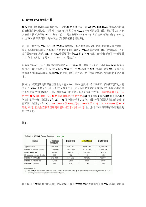
Logic Elements 38,400
Embedded System Blocks 160
Maximum RAM Bits 327,680
Maximum Macrocells 2,560
计算ESB 等效门数也可以采用和LSI LCA300K 比较的方法,即通过与实现相同容量RAM 在
LCA300K 所用的门数相比较,从而得到ESB 的每一bit 相当于多少门,从而计算出ESB 的
等效门数,参考图3。
Memory Function Gates Gates per Bit
1. 把FPGA 基本单元(如LUT+FF,ESB/BRAM)和实现相同功能的标准门阵列比较,
门阵列中包含的门数即为该FPGA 基本单元的等效门数,然后乘以基本单元的数目就
可以得到FPGA 门数估计值;
2. 分别用FPGA 和标准门阵列实现相同的功能,从中统计出FPGA 的等效门数,这种方
法比较多的依赖于经验数据。
等效门数约为130 万,所以最大系统门数为170 万。
结论:
FPGA 等效门数估计方法可以是把FPGA 资源基本单元(如LUT+FF,ESB)和实现相同
功能的标准门阵列相比得到FPGA 基本单元等效的门数,然后乘以单元的个数得到整个FPGA
xilinx luts和gate count换算 -回复
xilinx luts和gate count换算-回复Xilinx是一家半导体公司,专注于可编程逻辑器件的开发和生产。
在数字电路设计中,常常需要将逻辑函数转换为逻辑查找表(LUT)或门级计数(gate count)来评估电路的复杂性和资源消耗。
本文将介绍Xilinx LUTs 和gate count之间的换算关系,并提供一步一步的回答。
首先,我们来了解一下什么是逻辑查找表(LUT)。
LUT是数字逻辑电路中的基本构建模块,它能够将输入信号的组合映射到输出信号。
简单来说,LUT可以根据输入信号的不同组合产生不同的输出信号。
在Xilinx的FPGA(现场可编程门阵列)中,LUT是FPGA中逻辑单元的基本组织单元。
然后,我们来了解一下什么是门级计数(gate count)。
门级计数是用来衡量数字电路中使用的门电路(与门、或门、非门等)的数量。
它可以用来评估电路的复杂性和资源消耗。
现在,我们来介绍如何将Xilinx LUTs和gate count进行换算。
在Xilinx FPGA中,有一个常见的换算关系是1 LUT = 4个门。
这意味着,对于一个FPGA中的逻辑单元,如果它使用了1个LUT,则相当于使用了4个门。
同样地,如果一个逻辑单元使用了4个门,则相当于使用了1个LUT。
换句话说,如果你知道一个逻辑电路的LUT数目,你可以将其乘以4来得到该电路的门级计数。
同样地,如果你知道一个逻辑电路的门级计数,你可以将其除以4来得到该电路的LUT数目。
当然,这只是一个近似的换算关系。
在实际设计中,由于不同的逻辑电路结构和技术的差异,实际的换算关系可能会有所不同。
因此,在进行具体设计时,建议参考实际的技术文档和说明。
总结一下,Xilinx LUTs和gate count之间的换算关系可以通过1 LUT = 4个门来近似计算。
这个换算关系可以用来评估逻辑电路的复杂性和资源消耗。
然而,在实际设计中,需要注意不同的逻辑电路结构和技术的差异,以便更准确地计算LUTs和gate count之间的换算关系。
FPGA逻辑门计算
FPGA等效门数的计算方法有两种,一是把FPGA基本单元(如LUT+FF,ESB/BRAM)和实现相同功能的标准门阵列比较,门阵列中包含的门数即为该FPGA基本单元的等效门数,然后乘以基本单元的数目就可以得到FPGA门数估计值;二是分别用FPGA和标准门阵列实现相同的功能,从中统计出FPGA的等效门数,这种方法比较多的依赖于经验数据。
对于第一种方法,FPGA包括LUT/FF/RAM等资源,分析各种资源等效门数时,总原则是等效原则,就是实现相同的功能,在标准门阵列中需要的门数就是FPGA该资源等效门数,例如实现一个带寄存器输出的4输入XOR,在FPGA中需要用一个LUT和1个FF实现,在标准门阵列中一般要用21个与非门实现,于是1个LUT+1个FF等效于21个门。
对ESB(BRAM),由于用标准门阵列实现1bit的RAM时一般需要4个门,因此ESB/BARM 做RAM使用时,1bit等效4个门,对Altera FPGA中一个2048bit的ESB,等效门数为8K。
光靠这些数据还不能比较准确地计算出FPGA的等效门数。
因为这只是一种简单情况,实际情况要复杂很多。
例如,如果实现的是带寄存器输出地2输入XOR,FPGA也要用1个LUT+FF,而标准门阵列只需要8个NAND,于是1个LUT+1个FF只等效于8个门。
同时特定功能的实现,在不同的标准门阵列系列中需要的门数也不一样,因此等效门的计算只能是个大概的数值。
也就是说对于某一具体型号FPGA的门数估计,与FPGA资源的用途有密切关系。
LUT用于实现2输入XOR 和4输入XOR等效门数不一样(分别为1和13);FF不带异步清零、复位、时钟使能和带这些端口的等效门数不同(分别为8和13);ESB(BRAM)做RAM使用时,1bit等效4个门,1个2048bit的BRAM等效8K门,但是做查找表使用时可能只相当于不到200门。
因此估计FPGA 的等效门数需要做更细致的分析。
FPGA 门数计算方法---------------------------

FPGA 门数计算方法我们在比较FPGA 的芯片参数时经常说某一款FPGA 是多少万门的,也有的说其有多少个LE ,那么二者之间有何关系呢?DEVE 版主的原创文章《FPGA 门数计算方法》与您讨论这个问题。
FPGA 等效门数的计算方法有两种,一是把FPGA 基本单元(如LUT+FF ,ESB/BRAM )和实现相同功能的标准门阵列比较,门阵列中包含的门数即为该FPGA 基本单元的等效门数,然后乘以基本单元的数目就可以得到FPGA 门数估计值;二是分别用FPGA 和标准门阵列实现相同的功能,从中统计出FPGA 的等效门数,这种方法比较多的依赖于经验数据。
对于第一种方法,FPGA 包括LUT/FF/RAM 等资源,分析各种资源等效门数时,总原则是等效原则,就是实现相同的功能,在标准门阵列中需要的门数就是FPGA 该资源等效门数,例如实现一个带寄存器输出的4输入XOR ,在FPGA 中需要用一个LUT 和1个FF 实现,在标准门阵列中一般要用21个与非门实现,于是1个LUT +1个FF 等效于21个门。
对ESB (BRAM ),由于用标准门阵列实现1bit 的RAM 时一般需要4个门,因此ESB/BARM 做RAM 使用时,1bit 等效4个门,对Altera FPGA 中一个2048bit 的ESB ,等效门数为8K 。
光靠这些数据还不能比较准确地计算出FPGA 的等效门数。
因为这只是一种简单情况,实际情况要复杂很多。
例如,如果实现的是带寄存器输出地2输入XOR ,FPGA 也要用1个LUT +FF ,而标准门阵列只需要8个NAND ,于是1个LUT+1个FF 只等效于8个门。
同时特定功能的实现,在不同的标准门阵列系列中需要的门数也不一样,因此等效门的计算只能是个大概的数值。
也就是说对于某一具体型号FPGA 的门数估计,与FPGA 资源的用途有密切关系。
LUT 用于实现2输入XOR 和4输入XOR 等效门数不一样(分别为1和13);FF 不带异步清零、复位、时钟使能和带这些端口的等效门数不同(分别为8和13);ESB (BRAM )做RAM 使用时,1bit 等效4个门,1个2048bit 的BRAM 等效8K 门,但是做查找表使用时可能只相当于不到200门。
xilinx luts和gate count换算

xilinx luts和gate count换算一、概述XilinxLUT和门数换算是一个重要的概念,用于理解XilinxFPGA 设计中的资源和性能。
本文档将详细介绍LUT和门数的含义、换算方法以及如何在实际设计中考虑这些因素。
二、LUT介绍LUT,即Look-Up Table(查找表),是一种常用的硬件实现技术,用于实现数字逻辑电路中的比较、映射和缓存功能。
LUT在Xilinx FPGA设计中非常重要,因为它允许设计者使用表格形式的数据存储来实现更复杂的逻辑功能,从而减少了逻辑综合所需的门数。
三、门数介绍门数是FPGA设计中的一个重要指标,用于衡量设计的复杂度和资源消耗。
在Xilinx FPGA中,门数通常是指可编程逻辑单元的数量,如触发器、乘法器等。
这些逻辑单元共同构成了FPGA的基本构建块,也是设计者必须考虑的资源。
四、换算规则LUT和门数的换算规则主要基于设计的功能和所使用的LUT位数。
一般来说,一个32位的LUT等同于大约250门的逻辑电路。
这是因为一个32位的LUT可以存储8位输入的8种可能状态,每个状态需要3个门来映射到输出。
此外,如果使用多个LUT,那么总门数会相应减少。
五、实际应用考虑在Xilinx FPGA设计中,考虑LUT和门数的换算非常重要。
首先,设计者需要了解所设计的功能所需的逻辑资源,并据此选择合适的LUT位数和FPGA型号。
其次,设计者需要权衡LUT和门数的选择,以获得最佳的性能和资源利用率。
最后,设计者需要考虑可扩展性,即设计的可移植性和重构性。
六、优化技巧为了优化LUT和门数的使用,设计者可以采取以下技巧:1. 尽可能使用固定LUT代替可变LUT,因为固定LUT的门数更少,而且可以减少时序约束问题。
2. 优化逻辑功能,使其更简单、更常见,以便使用已有的LUT或IP库。
3. 在设计中合理分配LUT和门数的比例,以充分利用FPGA的资源。
4. 合理布局和布线设计,以最大限度地减少资源浪费和性能损失。
xilinx luts和gate count换算 -回复
xilinx luts和gate count换算-回复Xilinx Look-Up Tables (LUTs) 和Gate Count 的换算是一项重要的设计任务,在FPGA(Field Programmable Gate Array)电路的设计过程中扮演重要角色。
本文将详细介绍LUTs 和Gate Count 的概念,并提供一步一步的方法来进行两者之间的换算。
首先,让我们从LUTs 的概念开始。
LUT 是FPGA 架构中的一个基本组件,它可以实现逻辑操作。
每个LUT 都包含一个输入LUT 端口和一个输出LUT 端口。
最常见的LUT 类型是4输入LUT(4-input LUT),它有4个输入和一个输出。
一个4-input LUT 具有16个输入组合和16个输出配置选项,可以实现任何4输入布尔函数。
而Gate Count 是指电路中的逻辑门数量。
逻辑门是基本的数字电路组件,可以执行与门(AND gate)、或门(OR gate)、非门(NOT gate)等逻辑操作。
在FPGA 设计中,逻辑门的数量对电路的复杂性和性能有很大的影响。
通常情况下,逻辑门的数量越多,电路的功能就越复杂。
接下来,我们将介绍如何进行LUTs 和Gate Count 之间的换算。
首先,我们需要知道我们要实现的特定功能的真值表。
真值表列出了对于每个输入组合的输出值。
例如,对于一个4输入的布尔函数,我们需要列出16个输入组合和对应的输出值。
接下来,我们会用真值表来设计一个电路,该电路的逻辑门数量被称为Gate Count。
要计算Gate Count,我们需要根据真值表中出现的逻辑操作来选择适当的逻辑门。
例如,假设我们要实现一个4输入的布尔函数F(A, B, C, D),真值表如下:A B C D F0 0 0 0 10 0 0 1 00 0 1 0 10 0 1 1 00 1 0 0 00 1 0 1 10 1 1 0 00 1 1 1 11 0 0 0 11 0 0 1 01 0 1 0 11 0 1 1 01 1 0 0 01 1 0 1 11 1 1 0 01 1 1 1 1根据真值表,我们可以看到F(A, B, C, D)=1 的输入组合有6 个(0000、0010、0101、0111、1000 和1111)。
fpga 相关运算 -回复
fpga 相关运算-回复FPGA相关运算:了解FPGA基础知识及其运算过程摘要:本文将介绍FPGA(Field-Programmable Gate Array)相关运算,包括FPGA的基础知识、FPGA的结构和编程方式以及FPGA运算的具体过程。
我们将逐步回答与FPGA相关运算相关的问题,帮助读者了解FPGA 的运算原理及其在不同领域的应用。
第一部分:FPGA基础知识1. 什么是FPGA?FPGA是一种可编程逻辑器件(Programmable Logic Device,PLD),它具有灵活的硬件配置能力。
与ASIC(Application-Specific Integrated Circuit,专用集成电路)相比,FPGA具有更大的逻辑门数量和布线资源,可以实现更复杂的功能。
2. FPGA的结构FPGA由逻辑单元(Logic Element,LE)、可编程开关、输入输出接口和片上存储器等组成。
其中,逻辑单元是FPGA的基本构建块,包含了与门、或门、非门等常用的逻辑电路元件。
3. FPGA的编程方式FPGA的编程方式主要有两种:硬件描述语言(Hardware DescriptionLanguage,HDL)和图形化编程工具。
常用的HDL包括VHDL和Verilog,它们用于描述FPGA硬件电路的功能和逻辑关系。
图形化编程工具则提供了一种直观的方式来描述电路图,并将其编程到FPGA上。
第二部分:FPGA运算过程1. FPGA运算的基本原理FPGA通过对硬件电路进行重新配置,实现各种不同的计算和逻辑操作。
在FPGA中,我们可以根据需求来设计并配置逻辑单元之间的连接关系,从而实现各种不同的功能。
2. FPGA运算的步骤(1)设计:根据需求和功能要求,使用HDL或图形化编程工具进行FPGA 电路的设计。
这一步骤包括逻辑电路的功能描述、时序约束和电路优化等。
(2)综合:将设计文件转换为FPGA可识别的网表级结构。
FPGA等效门数的计算方法
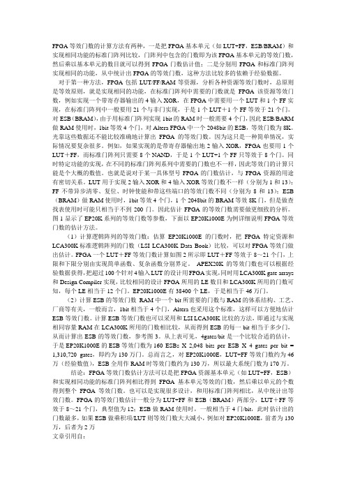
FPGA等效门数的计算方法有两种,一是把FPGA基本单元(如LUT+FF,ESB/BRAM)和实现相同功能的标准门阵列比较,门阵列中包含的门数即为该FPGA基本单元的等效门数,然后乘以基本单元的数目就可以得到FPGA门数估计值;二是分别用FPGA和标准门阵列实现相同的功能,从中统计出FPGA的等效门数,这种方法比较多的依赖于经验数据。
对于第一种方法,FPGA包括LUT/FF/RAM等资源,分析各种资源等效门数时,总原则是等效原则,就是实现相同的功能,在标准门阵列中需要的门数就是FPGA该资源等效门数,例如实现一个带寄存器输出的4输入XOR,在FPGA中需要用一个LUT和1个FF实现,在标准门阵列中一般要用21个与非门实现,于是1个LUT+1个FF等效于21个门。
对ESB(BRAM),由于用标准门阵列实现1bit的RAM时一般需要4个门,因此ESB/BARM 做RAM使用时,1bit等效4个门,对Altera FPGA中一个2048bit的ESB,等效门数为8K。
光靠这些数据还不能比较准确地计算出FPGA的等效门数。
因为这只是一种简单情况,实际情况要复杂很多。
例如,如果实现的是带寄存器输出地2输入XOR,FPGA也要用1个LUT+FF,而标准门阵列只需要8个NAND,于是1个LUT+1个FF只等效于8个门。
同时特定功能的实现,在不同的标准门阵列系列中需要的门数也不一样,因此等效门的计算只能是个大概的数值。
也就是说对于某一具体型号FPGA的门数估计,与FPGA资源的用途有密切关系。
LUT用于实现2输入XOR和4输入XOR等效门数不一样(分别为1和13);FF不带异步清零、复位、时钟使能和带这些端口的等效门数不同(分别为8和13);ESB (BRAM)做RAM使用时,1bit等效4个门,1个2048bit的BRAM等效8K门,但是做查找表使用时可能只相当于不到200门。
因此估计FPGA的等效门数需要做更细致的分析。
AlteraXilinx+FPGA逻辑门计算

1. Altera FPGA逻辑门计算FPGA等效门数的计算方法有两种,一是把FPGA基本单元(如LUT+FF,ESB/BRAM)和实现相同功能的标准门阵列比较,门阵列中包含的门数即为该FPGA基本单元的等效门数,然后乘以基本单元的数目就可以得到FPGA门数估计值;二是分别用FPGA和标准门阵列实现相同的功能,从中统计出FPGA的等效门数,这种方法比较多的依赖于经验数据。
对于第一种方法,FPGA包括LUT/FF/RAM等资源,分析各种资源等效门数时,总原则是等效原则,就是实现相同的功能,在标准门阵列中需要的门数就是FPGA该资源等效门数,例如实现一个带寄存器输出的4输入XOR,在FPGA中需要用一个LUT和1个FF实现,在标准门阵列中一般要用21个与非门实现,于是1个LUT+1个FF等效于21个门。
对ESB(BRAM),由于用标准门阵列实现1bit的RAM时一般需要4个门,因此ESB/BARM 做RAM 使用时,1bit等效4个门,对Altera FPGA中一个2048bit的ESB,等效门数为8K。
光靠这些数据还不能比较准确地计算出FPGA的等效门数。
因为这只是一种简单情况,实际情况要复杂很多。
例如,如果实现的是带寄存器输出地2输入XOR,FPGA也要用1个LUT+FF,而标准门阵列只需要8个NAND,于是1个LUT+1个FF只等效于8个门。
同时特定功能的实现,在不同的标准门阵列系列中需要的门数也不一样,因此等效门的计算只能是个大概的数值。
也就是说对于某一具体型号FPGA的门数估计,与FPGA资源的用途有密切关系。
LUT用于实现2输入XOR和4输入XOR 等效门数不一样(分别为1和13);FF不带异步清零、复位、时钟使能和带这些端口的等效门数不同(分别为8和13);ESB(BRAM)做RAM使用时,1bit等效4个门,1个2048bit的BRAM 等效8K门,但是做查找表使用时可能只相当于不到200门。
xilinxfpga电源的旁路电容值计算
xilinxfpga电源的旁路电容值计算
我们要计算Xilinx FPGA电源的旁路电容值。
首先,我们需要了解旁路电容的作用和计算方法。
旁路电容的主要作用是滤除电源线上的高频噪声,从而确保FPGA的稳定工作。
其计算公式为:C = I/f ×10^-6
其中,C 是电容值(单位:μF),I 是FPGA的电源电流(单位:A),f 是电源噪声频率(单位:MHz)。
这个公式告诉我们怎样根据FPGA的电源电流和电源噪声频率来选择合适的旁路电容值。
假设FPGA的电源电流为10A,电源噪声频率为100MHz,我们可以通过上述公式来计算旁路电容值。
计算结果为:旁路电容值是0 μF。
所以,为了确保Xilinx FPGA的稳定工作,我们应该选择一个接近0 μF 的旁路电容。
门位容量计算
门位容量计算
【实用版】
目录
1.门位容量计算的定义和重要性
2.门位容量计算的方法
3.门位容量计算的应用实例
4.门位容量计算的局限性和未来发展方向
正文
一、门位容量计算的定义和重要性
门位容量计算,是一种用于估计计算机系统或网络中门的数量和容量的方法。
在计算机科学中,门是指一个逻辑运算符,例如与门、或门、非门等。
门位容量计算是计算机科学中一个重要的研究领域,它可以用于评估计算机系统的性能和容量,从而优化计算机系统的设计和运行。
二、门位容量计算的方法
门位容量计算的方法主要包括以下两种:
1.基于布尔代数的方法:该方法利用布尔代数的性质,将逻辑电路转化为布尔代数表达式,然后通过求解布尔代数表达式来估计门的数量和容量。
2.基于图论的方法:该方法将逻辑电路转化为网络图,然后利用图论的性质和算法来估计门的数量和容量。
三、门位容量计算的应用实例
门位容量计算在计算机科学中有广泛的应用,例如:
1.在计算机系统设计中,门位容量计算可以用于估计系统的性能和容量,从而优化系统的设计和运行。
2.在计算机网络设计中,门位容量计算可以用于估计网络的吞吐量和延迟,从而优化网络的拓扑结构和协议设计。
四、门位容量计算的局限性和未来发展方向
尽管门位容量计算在计算机科学中有重要的应用,但它也存在一些局限性,例如:
1.门位容量计算只能估计门的数量和容量,不能估计门的真实状态和行为。
2.门位容量计算的方法和算法需要基于假设和简化,因此它们的估计结果可能与实际结果存在误差。
xilinx luts和gate count换算 -回复
xilinx luts和gate count换算-回复Xilinx LUTs和Gate Count是FPGA(Field-Programmable Gate Array)设计中常用的两个指标,用于衡量FPGA资源的使用情况和设计的复杂度。
本文将详细介绍Xilinx LUTs和Gate Count之间的换算关系,并解释它们对FPGA设计的重要性。
首先,让我们来了解一下Xilinx LUTs和Gate Count的定义。
LUT (Look-Up Table)是FPGA中的基本逻辑单元,用于实现数字逻辑功能。
每个LUT都有一个特定的输入和一个输出,其输出值由输入值确定。
Xilinx LUTs指的是FPGA中可用的LUT的数量,它反映了FPGA资源利用的情况。
Gate Count是对数字逻辑电路中所使用的逻辑门数量的计数。
逻辑门是用于实现各种计算和操作的基本元件,例如与门、或门、非门等。
Gate Count可以用来衡量一个设计的复杂程度,通常表示为逻辑门的数量。
为了将Xilinx LUTs和Gate Count进行换算,我们首先需要了解它们之间的关系。
在Xilinx的FPGA中,一个LUT通常可以实现一个逻辑门的功能。
因此,我们可以假设Xilinx LUTs的数量等于逻辑门的数量,即Xilinx LUTs = Gate Count。
然而,需要注意的是,实际的LUT数量并不完全等于逻辑门数量。
这是因为FPGA中的LUT不仅用于实现逻辑功能,还用于存储和传输数据。
在设计中,还要考虑到LUT的用途和功能,以确保资源的合理利用。
另外,Xilinx还提供了一些高级功能,例如RAM(Random Access Memory)和DSPs(Digital Signal Processors),这些功能通常需要额外的资源,并不计入Xilinx LUTs和Gate Count中。
因此,在设计过程中,还需要根据设计中使用的特殊功能和组件来确定资源的使用情况。
xilinx luts和gate count换算 -回复
xilinx luts和gate count换算-回复标题:Xilinx LUTs与Gate Count的换算解析在FPGA(Field-Programmable Gate Array)设计中,LUTs(Look-Up Tables)和Gate Count是两个重要的概念,它们分别代表了FPGA 的逻辑资源和门电路数量。
理解这两个概念及其之间的换算关系,对于优化FPGA设计、提高资源利用率具有重要意义。
以下我们将详细探讨Xilinx LUTs和Gate Count的换算过程。
一、理解LUTs和Gate Count1. LUTs(Look-Up Tables)LUTs是FPGA中的基本逻辑单元,它是一个存储器结构,可以存储多组预定义的输入输出数据。
当给定一个输入值时,LUT会查找并返回相应的输出值。
在Xilinx FPGA中,每个LUT通常包含4或6个输入位和一个输出位。
2. Gate CountGate Count是指FPGA中门电路的数量,包括逻辑门(如AND、OR、NOT等)和触发器。
它是衡量FPGA逻辑复杂度和资源使用情况的一个重要指标。
二、Xilinx LUTs与Gate Count的关系在Xilinx FPGA中,每个LUT通常被实现为一个可配置的查找表和一些附加逻辑,这些附加逻辑包括一个可选的进位链和一个可选的寄存器(D Flip-Flop)。
因此,一个LUT可以看作是一个基本的逻辑门集合。
具体来说,一个4输入LUT可以实现任何4变量的布尔函数,相当于实现了16个可能的逻辑门组合。
同样,一个6输入LUT可以实现任何6变量的布尔函数,相当于实现了64个可能的逻辑门组合。
然而,需要注意的是,虽然一个LUT可以实现多个逻辑门的功能,但并不意味着一个LUT就等同于一个固定的门数。
这是因为LUT的实际门数取决于其内部实现的特定逻辑功能。
例如,如果一个4输入LUT只实现了简单的AND门功能,那么它的实际门数就是1;但如果它实现了更复杂的逻辑函数,那么其实际门数可能会超过16。
- 1、下载文档前请自行甄别文档内容的完整性,平台不提供额外的编辑、内容补充、找答案等附加服务。
- 2、"仅部分预览"的文档,不可在线预览部分如存在完整性等问题,可反馈申请退款(可完整预览的文档不适用该条件!)。
- 3、如文档侵犯您的权益,请联系客服反馈,我们会尽快为您处理(人工客服工作时间:9:00-18:30)。
Device
XC4003E XC4005E/XL
XC4006E XC4008E XC4010E/XL XC4013E/XL XC4020E/XL XC4025E XC4028EX/XL XC4036EX/XL XC4044XL XC4052XL XC4062XL
Number of CLBs
100 196 256 324 400 576 784 1024 1024 1296 1600 1936 2304
The CLBs of the XC4000 Series devices each contain three function generators and two registers (Figure 1). Additional resources in the block include dedicated arithmetic carry logic. Using Table 3 as a guide, the potential gate count for a single CLB can be derived. (Table 3 lists the gate counts for a sampling of logic functions; these gate counts are taken directly from a typical mask-programmed gate array’s library.)
Gate Count
1 4 6 9 9
6 8 12
Table 4: Capacity ranges for XC4000 Series CLB Resources
CLB Resource Gate range per 4-input LUT (2 per CLB) Gate range per 3-input LUT Gate range per flip-flop (2 per CLB) Total gate range per CLB
Function
Combinatorial functions: 2-input NAND 2-to-1 Multiplexer 3-input XOR 4-input XOR 2-bit carry-save full adder
Register functions: D flip-flop D flip-flop with set or reset D flip-flop with reset and clock enable
Typical Gate Range (Logic and Memory)
2K - 5K 3K - 9K 4K - 12K 6K - 15K 7K - 20K 10K - 30K 13K - 40K 15K - 45KK - 80K 33K - 100K 40K - 130K
Max. Logic Gates (No Memory) 3K 5K 6K 8K 10K 13K 20K 25K 28K 36K 44K 52K 62K
Max. Memory Bits (No Logic) 3K 6K 8K 10K 13K 18K 25K 33K 33K 42K 51K 62K 74K
Table 1: XC4000 Series FPGA Capacity Metrics
Maximum Logic Gates
“Maximum Logic Gates” is the metric used to estimate the maximum number of gates that can be realized in the FPGA device for a design consisting of only logic functions. (On-chip memory capabilities are not factored into this metric.) This metric is based on an estimate of the typical number of usable gates per configurable logic block (CLB) or logic cell multiplied by the total number of such blocks or cells. This estimate, in turn, is based on an analysis of the architecture of the logic block and empirical data obtained by comparing the implementation of entire system-level designs in the FPGA devices and traditional gate arrays.
APPLICATION NOTE
®
Gate Count Capacity Metrics for
FPGAs
XAPP 059 Feb. 1, 1997 (Version 1.1)
Application Note
Summary Three metrics are defined to describe FPGA device capacity: Maximum Logic Gates, Maximum Memory Bits, and Typical Gate Range. The methodology used to determine these values is described. Xilinx Family XC4000 Series, XC5000 Series
the actual obtainable usage is estimated as about 28.5 gates per XC4000 Series CLB. For example, the XC4020E, with 784 CLBs, is rated with a capacity of 20,000 Maximum Logic Gates (784 x 28.5 = 22,344). (This factor is derated to 24 gates/CLB in the XC4025E device, as its utilization is somewhat limited by the available routing.)
Gate Range 1 to 9 1 to 6 6 to 12
15 to 48
Estimated typical number of gates per CLB 28.5
The function generators are implemented as memory lookup tables (LUTs); the F and G function generators are 4-input LUTs, and the H function generator is a 3-input LUT. Each LUT is capable of generating any logic function of its inputs; thus, in a given application, a 4-input LUT might be used for any operation ranging from a simple inverter or 2-input NAND (1 gate) to a complex function of 4 inputs, such as a 4-input exclusive-OR (9 gates) or, along with the built-in carry logic, a 2-bit full adder (9 gates). Similarly, the registers in the CLB account for anywhere from 6 to 12 equivalent gates each, dependent on whether built-in functions such as the asynchronous preset/clear and clock enable are utilized.
In the tables in this document (and in the corresponding product specifications in the Xilinx 1996 Programmable Logic Data Book), three metrics are supplied to measure the capacity of Xilinx FPGAs in terms of both gate counts and bits of memory, as shown in Table 1 and Table 2: “Maximum Logic Gates,” “Maximum Memory Bits” (only for FPGAs with on-chip memory capability), and “Typical Gate Range.” These tables also list the actual number of Configurable Logic Blocks (CLBs) or logic cells available in each device.
