龙尚C5300模块硬件接口手册_V2.0
Philips SCO5300 移动办公包说明书

PhilipsPack d'accessoires pourPC portableSCO5300Voyagez mieux !Enceintes USB pour PC portable, souris filaire pour PC portable, Webcam USBUne expérience multimédia plus vraie que nature•Connexion facile sur PC ou ordinateur portableFacile à utiliser•Connexion facile via USB sur votre PC ou ordinateur portableDesign contemporain•Un design et des performances à couper le souffle*Du sens et de la simplicitéCaractéristiques Pack d'accessoires pour PC portablePoints forts Pour PC ou ordinateur portable Connexion possible avec un PC ou un ordinateur portable Plug-and-play USB Plug-and-play USB signifie que l'appareil est conforme aux normes USB et qu'il est reconnu par les PC ou ordinateurs portables. Cela rend plus simple et plus rapide le branchement d'appareils USB.Connectivité•Connecteur: Port USB •USB: USB 2.0Convivialité•Installation aisée: Plug-and-play •Housse de transport incluseContenu de l'emballage •Guide de mise en routeConfiguration requise •USB: Port USB libreEnceintes •Système magnétique en néodymeCarton externe •EAN:87 12581 44022 0•Nombre d'emballages: 5•Poids brut: 3,4 kg •Carton externe (l x l x H): 37 x 33,2 x 25 cm •Poids net: 1,45 kg •Tare: 1,95 kg Dimensions de l'emballage •EAN:87 12581 44021 3•Nombre de produits inclus: 1•Type d'emballage: Carton •Dimensions de l'emballage (l x H x P): 31,8 x 21,4 x 7 cm •Poids brut: 0,68 kg •Poids net: 0,29 kg •Tare: 0,39 kg Date de publication2009-08-11Version: 2.0.812 NC: 8670 000 41892EAN: 87 12581 44021 3© 2009 Koninklijke Philips Electronics N.V.Tous droits réservés.Les caractéristiques sont sujettes à modification sans préavis. Les marques commerciales sont la propriété de Koninklijke Philips Electronics N.V. ou de leurs détenteurs 。
chipcon smartrf cc2500单片低成本低能耗RF收发芯片 说明书

500kbps z 较低的电流消耗(RX 中 15.6mA) z 可编程控制的输出功率,可达+1dBm z 优秀的接收器选择性和模块化性能 z 极少的外部元件:芯片内频率合成器,
不需要外部滤波器或 RF 转换 z 可编程控制的基带调制解调器 z 理想的多路操作特性 z 可控的数据包处理硬件 z 快速频率变动合成器带来的合适的频
第 2 页 共 61 页
目录 1 缩写词 ....................................................................................................................... 2 2 绝对最大等级 ........................................................................................................... 5 3 工作条件 ................................................................................................................... 5 4 电气规范 ................................................................................................................... 6 5 常规特性 .....................................................................................
5300UG安全与音频系统电缆手册说明书
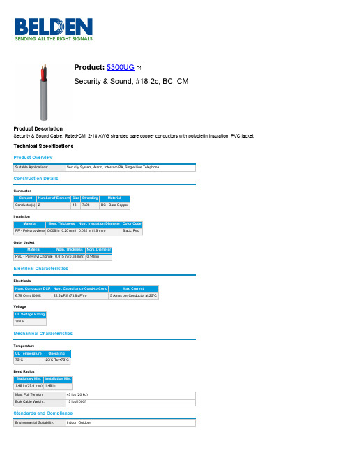
Product Overview
Suitable Applications:
Security System, Alarm, Intercom/PA, Single Line Telephone
Construction Details
Conductor
Element Number of Element Size Stranding
5300UG 008C500 Gray
5300UG 008U1000 Gray 612825159186
5300UG 008U500 Gray 612825159193
5300UG 009C500 White 612825159209
5300UG 009U1000 White 612825159216
All sales of Belden products are subject to Belden's standard terms and conditions of sale.
Belden believes this product to be in compliance with all applicable environmental programs as listed in the data sheet. The information provided is correct to the best of Belden's knowledge, information and belief at the date of its publication. This information is designed only as a general guide for the safe handling, storage, and any other operation of the product itself or the one that it becomes a part of. The Product Disclosure is not to be considered a warranty or quality specification. Regulatory information is for guidance purposes only. Product users are responsible for determining the applicability of legislation and regulations based on their individual usage of the product.
FIBOCOM_G510 硬件用户手册_V1.1.4

3.4 开关机................................................................................................................................................. 13
2
简介.................................................................................................................................................. 7
注意
由于产品版本升级或其他原因,本文档内容会不定期进行更新。除非另有约定,本文档仅作为使用指导, 本文档中的所有陈述、信息和建议不构成任何明示或暗示的担保。
商标申明
为深圳市广和通无线股份有限公司的注册商标,由所有人拥有。
版本记录
文档版本 V1.0.0 V1.0.1 V1.0.2 V1.0.3 V1.0.4 V1.0.5 V1.0.6 V1.0.7 V1.0.8 V1.0.9 V1.1.0 V1.1.1 V1.1.2 V1.1.3 V1.1.4 更新日期 2013-02-04 2013-04-03 2013-04-26 2013-05-09 2013-06-03 2013-06-17 2013-07-31 2013-08-12 2013-11-26 2014-08-19 2014-12-26 2015-04-21 2015-08-24 2015-12-30 2016-07-14 说明 初始版本 更新 LPG,UART 更新性能描述 更新 3.7 串口,添加 UART2 和 HOST UART 描述 删除支持 2 路 ADC 描述,更新管脚定义说明 更新图 3-8,图 3-9 和图 5-2 更新文档名称 增加 3.6.3 章节 增加 G510-A20-00 更新 SIM_DATA 的描述 公司名称变更,更新为“深圳市广和通无线股份有限公司” PCB Layout 部分增加顶部视图说明 更新 logo 增加 PCB SMT 提醒 删除适用型号 G510-A20-00
SC005002 V5接口原理与交换机侧V5数据配置 ISSUE2.0
AN用户呼叫流程 用户呼叫流程
AN用户呼叫普通用户之一
A N E S A L HA K A T B IS _ C AL C T N L O A IO 分 用 释 A L C T NC M L T 分用 L O A IO _ O P E E 及5 定 V释 侧 送 稳 送稳 送忙 L E
普通用户呼叫AN用户之一
主链路 运载保护协议、控制协议、链路控制、和BCC协议的时隙(物 理C通道)所在的链路 次链路 主链路的备用C通路 V5.2接口只能有一条主链路和一条次链路
华为机密, 华为机密,未经许可不得扩散
文档密级: 文档密级:内部公开
保护组
保护组:起保护V5接口的作用 保护组一:主、次链路的物理C 保护组二:其他链路上的物理C 一个V5.2接口肯定有保护组一。 根据需要,可以建立保护组二(一般不使用)
华为机密, 华为机密,未经许可不得扩散
文档密级: 文档密级:内部公开
课程内容
第一章 V5接口的概念 接口的概念 第二章 交换机侧 接口数据配置 交换机侧V5接口数据配置
华为机密, 华为机密,未经许可不得扩散
文档密级: 文档密级:内部公开
简介
V5接口是一种信令标准,它和我们以前学习过的信令方式有很 多相通的地方,但也有些特点,V5难度不是太大。 C&C08交换机128模块V5数据的制作的步骤和命令比较简单。
华为机密, 华为机密,未经许可不得扩散
文档密级: 文档密级:内部公开
学习目标
学习完本课程,您应该能够: 学习完本课程,您应该能够:
掌握V5接口的基本原理 掌握 接口的基本原理 掌握正常的V5接口对接流程 掌握正常的 接口对接流程 掌握正常的呼叫流程 掌握交换机侧V5接口的数据设定 掌握交换机侧 接口的数据设定
ICOP 3.5英寸CPU模块说明书
1
μProcessor Module
2
Tiny Module
3
PC/104 CPU module
4
Half-Size CPU module
5
3.5” CPU module
6
Peripheral Module
7
Display Product Series
8
Accessories & Technical Information
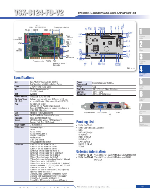
PS/2 KB/Mouse VGA Connector LAN
COM1
Packing List
• VSX-6124-FD-V2 • CD for User’s Manual & Driver x1 • Cable
HDD 40P (2.54) x1 FDD (2.0) x1 PRINT (2.54) x1 USB (2.54) x2 GPIO (2.54) x1 RS-232 (2.54) x3 YKB x1
GPIO LCD Connector
Power Connector USB x 2 COM 1 USB x 2 LAN
VGA
PS2 KBD/Mouse
Power Connector PC/104 FDD Flexible DC Power Connector
116.9 105.1
76.2
40.7 27.6 24.4 19.7 0.03.0 Ø3.2
Ordering information
• VSX-6124-FD-V2 Vortex86SX Half-Size CPU Module with 128MB DDR2 • VSX-6124-FDC-V2 Vortex86SX Half-Size CPU Module with 128MB
Axiom 爱克信V硬件手册(8RC)
RBH 将不断创新,不断提高爱克信系统的功能性和可靠性,因此此书所包含的信 息将不断更新。本手册信息如有更改,恕不另行通知。RBH 公司不对本书作任何 担保,包括但不限于适销性和特定用途适用性的明示暗示担保。RBH 公司及其代 理商、经销商或工程商对于本书所含错误及其供应、性能或使用所造成的意外性或 随发性损失概不负责。
中国地区销售及服务中心:
深圳市爱克信安全技术有限公司
深圳市福田区益田路 4068 号卓越时代广场 1211 邮编:518048 Tel: 86-755-23996161 Fax: 86-755-23996171 Email: support@
RBH ACCESS TECHNOLOGIES INC.
4. 由于您所采购的软件配置/模块不同,对硬件的配置和要求也 会有所改变,如果您有疑问,请与我们的代理商或服务支持 中心联系。
目录
版权和商标.............................................................................................................................................. I 目录.......................................................................................................................................................... 1 系统概述.................................................................................................................................................. 4 系统图...................................................................................................................................................... 6
MOXA UC-5100系列IIoT网关产品说明说明书

UC-5100SeriesArm Cortex-A81GHz IIoT gateway with1mini PCIe expansion slot for wireless module,4 serial ports,2CAN ports,4DIs,4DOsFeatures and Benefits•Armv7Cortex-A81000MHz processor•Dual auto-sensing10/100Mbps Ethernet ports•4software-selectable RS-232/422/485ports supporting all signals•Dual CAN ports with industrial CAN2.0A/B protocol supported•Moxa Industrial Linux with10-year long-term support•Mini PCIe socket for Wi-Fi/cellular module•SD slot for storage expansion•-40to85°C wide temperature range and-40to70°C with LTE enabled•IEC61000-6-2/6-4standards for harsh industrial environmentsCertificationsIntroductionThe UC-5100Series embedded computers are designed for industrial automation applications.The computers feature4RS-232/422/485full signal serial ports with adjustable pull-up/pull-down resistors,2CAN ports,2Ethernet ports,4digital input channels,4digital output channels,USB interface,and an SD slot in a compact,front-end access housing.To fulfill various industrial applications,the UC-5100Series computing platform provides models with2CAN ports and a mini PCIe slot for wireless connections featuring a dual-SIM design for network redundancy.The UC-5100’s vertical DIN-rail form factor makes it easy to install the computer in a small cabinet.This space-saving solution also facilitates easy wiring, making the UC-5100a great choice as front-end embedded controllers for industrial applications.Furthermore,all models are equipped with Moxa Industrial Linux that comes with10-year long-term support as well as optimized software features.Appearance UC-5101UC-5102UC-5111UC-5112SpecificationsComputerCPU Armv7Cortex-A81GHzPre-installed OS Linux Debian9kernel4.4(Moxa Industrial Linux) DRAM512MB DDR3Storage Pre-installed8GB eMMCStorage Slot SD slots x1Expansion Slots UC-5102-LX:mPCIe slots x1UC-5112-LX:mPCIe slots x1UC-5102-T-LX:mPCIe slots x1UC-5112-T-LX:mPCIe slots x1Computer InterfaceUSB2.0USB2.0hosts x1,type-A connectorsNumber of SIMs2SIM Format MicroSerial Ports RS-232/422/485ports x4,software selectable(RJ45)Digital Input DIs x4Digital Output DOs x4Buttons Reset button,DIP switch for serial and CAN port configuration Console Port RS-232(TxD,RxD,GND),RJ45output(115200,n,8,1) Ethernet InterfaceEthernet Ports Auto-sensing10/100Mbps ports(RJ45connector)x2 Magnetic Isolation Protection 1.5kV(built-in)Serial InterfaceSerial Ports4x RS-232/422/485Data Bits5,6,7,8Parity None,Even,Odd,Space,MarkStop Bits1,1.5,2Serial SignalsRS-232TxD,RxD,RTS,CTS,DTR,DSR,DCD,GNDRS-422Tx+,Tx-,Rx+,Rx-,GNDRS-485-2w Data+,Data-,GNDRS-485-4w Tx+,Tx-,Rx+,Rx-,GNDCAN InterfaceNo.of Ports UC-5111-LX:2UC-5111-T-LX:2UC-5112-LX:2UC-5112-T-LX:2Signals UC-5111-LX:CAN_L,CAN_H,CAN Signal GNDUC-5111-T-LX:CAN_L,CAN_H,CAN Signal GNDUC-5112-LX:CAN_L,CAN_H,CAN Signal GNDUC-5112-T-LX:CAN_L,CAN_H,CAN Signal GNDTerminator UC-5111-LX:N/A,120ohms(by DIP)UC-5111-T-LX:N/A,120ohms(by DIP)UC-5112-LX:N/A,120ohms(by DIP)UC-5112-T-LX:N/A,120ohms(by DIP)Digital InputsVoltage0to0.8VDC2.0to5.5VDCDigital OutputsCurrent Rating24mA per channelVoltage0to0.55VDC2.5to3.3VDCLED IndicatorsSystem Power x1System Ready x1LAN2per port(10/100Mbps)Serial2per port(Tx,Rx)CAN UC-5111-LX:2per port(Tx,Rx),UC-5112-LX:2per port(Tx,Rx),UC-5111-T-LX:2perport(Tx,Rx),UC-5112-T-LX:2per port(Tx,Rx)Wireless Signal Strength UC-5112-LX:Cellular/Wi-Fi x3UC-5102-LX:Cellular/Wi-Fi x3UC-5102-T-LX:Cellular/Wi-Fi x3UC-5112-T-LX:Cellular/Wi-Fi x3Physical CharacteristicsHousing MetalWeight600g(1.32lb)Dimensions57x136x100mm(2.24x5.35x3.94in)Installation DIN-rail mounting,Wall mounting(with optional kit)Power ParametersInput Voltage9to48VDCInput Current0.95A@9VDC,0.23A@48VDCPower Consumption6WEnvironmental LimitsOperating Temperature Standard Models:-10to60°C(14to140°F)Wide Temp.Models:Product only:-40to85°C(-40to185°F)With LTE accessory:-40to70°C(-40to158°F)With Wi-Fi accessory:-10to70°C(14to158°F)Storage Temperature UC-5101-LX:-20to70°C(-4to158°F)UC-5102-LX:-20to70°C(-4to158°F)UC-5111-LX:-20to70°C(-4to158°F)UC-5112-LX:-20to70°C(-4to158°F)UC-5101-T-LX:-40to85°C(-40to185°F)UC-5102-T-LX:-40to85°C(-40to185°F)UC-5111-T-LX:-40to85°C(-40to185°F)UC-5112-T-LX:-40to85°C(-40to185°F)Ambient Relative Humidity5to95%(non-condensing)Vibration2Grms@IEC60068-2-64,random wave,5-500Hz,1hr per axis(without USB devicesattached)Shock IEC60068-2-27Standards and CertificationsSafety UL60950-1,EN60950-1,IEC60950-1EMC EN55032/24,EN61000-6-2/-6-4EMI CISPR32,FCC Part15B Class AEMS IEC61000-4-2ESD:Contact:4kV;Air:8kVIEC61000-4-3RS:80MHz to1GHz:10V/mIEC61000-4-4EFT:Power:2kV;Signal:1kVIEC61000-4-5Surge:Power:2kV;Signal:1kVIEC61000-4-6CS:10VIEC61000-4-8PFMFGreen Product RoHS,CRoHS,WEEEReliabilityAlert Tools External RTC(real-time clock)Automatic Reboot Trigger External WDT(watchdog timer)MTBFTime UC-5101-LX:728,216hrsUC-5101-T-LX:728,216hrsUC-5102-LX:704,409hrsUC-5102-T-LX:704,409hrsUC-5111-LX:584,470hrsUC-5111-T-LX:584,470hrsUC-5112-LX:568,997hrsUC-5112-T-LX:568,997hrsStandards Telcordia(Bellcore)Standard TR/SR WarrantyWarranty Period5yearsDetails See /warrantyPackage ContentsDevice1x UC-5100Series computer Documentation1x quick installation guide1x warranty cardInstallation Kit1x DIN-rail kit(preinstalled)1x power jackCable1x RJ45-to-DB9console cableDimensionsOrdering InformationModel Name CPU RAM Storage Ethernet Serial CAN SD USB Mini PCIeOperatingTemp.UC-5101-LX1GHz512MB8GB24–11–-10to60°CUC-5102-LX 1GHz512MB8GB24–111(dual-SIMsocket)-10to60°CUC-5111-LX1GHz512MB8GB24211–-10to60°CUC-5112-LX 1GHz512MB8GB242111(dual-SIMsocket)-10to60°CUC-5101-T-LX1GHz512MB8GB24–11–-40to85°CUC-5102-T-LX 1GHz512MB8GB24–111(dual-SIMsocket)-40to85°CUC-5111-T-LX1GHz512MB8GB24211–-40to85°CUC-5112-T-LX 1GHz512MB8GB242111(dual-SIMsocket)-40to85°CAccessories(sold separately)Power AdaptersPWR-24270-DT-S1Power adapter,input voltage90to264VAC,output voltage24V with2.5A DC load Power CordsPWC-C7US-2B-183Power cord with United States(US)plug,10A/125V,1.83mPWC-C7EU-2B-183Power cord with Continental Europe(EU)plug,2.5A/250V,1.83mPWC-C7UK-2B-183Power cord with United Kingdom(UK)plug,2.5A/250V,1.83mPWC-C7CN-2B-183Power cord with two-prong China(CN)plug,1.83mPWC-C7AU-2B-183Power cord with Australian(AU)plug,2.5A/250V,1.83mCellular Wireless ModulesUC-LTE-CAT1-EU LTE cellular module,with2each of M2and M2.5mounting screws,for Asia and Europe bands1,3,8,20,28UC-LTE-CAT1-AUS LTE cellular module,with2each of M2and M2.5mounting screws,for Australia and New Zealandbands3,5,8,28UC-LTE-CAT4-CN LTE cellular module,with2each of M2and M2.5mounting screws,for LTE(FDD)bands B1,B3,B8and LTE(TDD)bands B39,B40,B41(38)Wi-Fi Wireless ModulesUC-WiFi-USB802.11a/b/g/n/ac,2.4/5GHz Wi-Fi module with2each of M2and M2.5AntennasANT-WDB-ARM-0202plus ADP 2.4/5GHz omni-directional antenna,2/2dBi,RP-SMA-type(male)connectorANT-LTE-OSM-03-3m BK Multi-band antenna that covers700-2700MHz.Specially designed for2G,3G,and4G applications.Magnetic mounting is availableANT-LTE-ASM-04BK LTE Stick antenna that covers704-960/1710-2620MHz providing omnidirectional radiation with a gainof4.5dBi.ANT-LTE-ASM-05BK LTE stick antenna that covers704-960/1710-2620MHz with a gain of5dBi.ANT-LTE-OSM-06-3m BK MIMO Multi-band antenna that covers700-2700/2400-2500/5150-5850MHz frequencies.Screw-fastenedmounting and full IP67waterproofing are available.SMA-Adapter SMA adapter for UC-2104and UC-5100SeriesDIN-Rail Mounting KitsDK-UC-5000DIN-rail mounting kit with screws for the UC-5000SeriesWall-Mounting KitsWM-UC-5000Wall-mounting kit with screws for the UC-5000Series©Moxa Inc.All rights reserved.Updated Mar09,2020.This document and any portion thereof may not be reproduced or used in any manner whatsoever without the express written permission of Moxa Inc.Product specifications subject to change without notice.Visit our website for the most up-to-date product information.。
龙尚U9300C 模块硬件接口手册_V1.2
U9300C 模块硬件接口手册_V1.2
共 53 页
第 1 页
重要声明 版权声明 版权所有:龙尚科技(上海)有限公司 本资料及其包含的所有内容为龙尚科技(上海)有限公司所有,受中国法律及适 用之国际公约中有关著作权法律的保护。未经龙尚科技(上海)有限公司书面授 权,任何人不得以任何形式复制、传播、散布、改动或以其它方式使用本资料的 部分或全部内容,违者将被依法追究责任。 不保证声明 龙尚科技 (上海) 有限公司不对此文档中的任何内容作任何明示或暗示的陈述或 保证, 而且不对特定目的的适销性及适用性或者任何间接、特殊或连带的损失承 担任何责任。 保密声明 本文档(包含任何附件)包含的信息是保密信息。接收人了解其获得的本文档是 保密的, 限用于规定的目的外不得用于任何目的,也不得将本文档泄露给任何第 三方。 免责声明 本公司不承担由于客户不正常操作造成的财产或者人身伤害责任。 请客户按照手 册中的技术规格和参考设计开发相应的产品。在未声明之前,本公司有权根据技 术发展的需要对本手册内容进行更改,且更改版本不另行通知。
U9300C 模块硬件接口手册_V1.2 共 53 页 第 3 页
U9300C 模块硬件接口手册_V1.2
共 53 页
第 2 页
目录
1. 引言............................................................................................................................................. 8 1.1. 文档目的...........................................................
CDM530AM 530 3G无线路由器的中文使用手册 东方巨狮总代理
Step 4: 点选下一步继续
Step 5: 选择是否使用无线网络后继续 下一步。
Step 6: 输入 SSID, 频道 以及安全性 设定,再点选下一步继续。
Step 7: 点选 3G 图示进行下一步。
Step 8-1: 请输入 ISP 提供给您的 3G 服 务信息继续下一步。 如果您有 3G 设定上的问题请 洽系统服务商。
步骤 8: 点选完成来结束。
Step 8-2: 或选择自动侦测让本模式为您 设定。
Step 9: 重新开启路由器。
Step 10: 储存设定值。
Step 11: 点选下一步去测试 WAN 端网 络,或可勾选取消测试。
Step 12: 设定完成。
2.2 Easy Setup by Configuring Web Pages
您也可以浏览网页上的使用者接口来设定本产品。
快速安装手册
CDM530 无线可携式路由器
Chapter 1 产品硬件安装
感谢您使用本产品,本产品是一台专为数字家庭用户以及小型企业办公所设计的 3G 可携式路由器,请依照以下硬件和软件快速安装步骤,谢谢 !!
1.1 Package List
Items 1
概述
3G可携式路由器
内容物
数量 12RJ源自5网络线开始进行设定在网址列输入IP地址。 (http://192.168.123.254)
在系统密码栏中输入预设密 码 “admin” 后按下登入 选择您的语言
选择精灵以简易的方法来进 行基本设定。
点选下一步来进行设定精 灵。
用设定精灵来进行设定
步骤 1:设定系统密码 设定你的系统密码。 (预设:admin)
其它 指示灯 灯号指示说明:
brocade_5300_switch_CN

产品彩页存储区域网络一款适用于虚拟化数据中心的业界领先交换机亮 点• 在单域、优化的2U 机型中提供了最多80个的完全8 Gbit/sec 1:1的高性能端口 • 提供了同类最佳的企业SAN 交换机端口密度和可扩展性以及冗余、可热插拔组件和不间断软件升级• 拥有自动感应1、2、4和8 Gbit/sec 功能以及与博科和博科M 系列fabric 架构的本地化操作,可保护现有的设备投资 • 特别提供了按需增加端口(Ports and Demand)功能,实现了简单快捷且经济高效的可扩展性,可以16端口的增量从48个端口扩展到80个端口• 提供了服务质量(QoS)等适应性网络服务,可帮助优化整合式虚拟环境中应用性能• 支持光纤通道(FC)集成路由(IR),可在在保持远程fabric 架构隔离的同时进行选择性设备共享,实现更高水平的可扩展性和故障隔离• 通过提高带宽并降低功耗,从而改善节能省电性随着业务数据价值和数量的持续增长,各机构所需的技术解决方案不仅要易于实施和管理,还要能以最小中断实现增长和变化。
Brocade 5300交换机是专为快速增长关键业务环境中连接的整合而设计的,在高效设计的2U 机型的48、64和80端口配置中结合进了1、2、4和8 Gbit/sec 技术。
其密度、性能以及“用多少买多少”(pay-as-you-grow)可扩展性的三方面优势使得它可在降低虚拟化服务器和存储复杂性的同时提高服务器和存储利用率。
Brocade 5300可用于fabric 架构核心端或分层式核心-边缘架构基础设施边缘端,通过到Brocade Fabric OS (FOS)和M-Enterprise OS (M-EOS)*环境的原生E_Port 连接,实现与现有博科交换机的无缝操作。
其渐进式设计带来了极高的电源、散热和机架密度效率,从而可帮助实现大中型服务器和存储的整合。
Brocade 5300还包含进了适应性网络功能,可在为数据中心应用提供最高等级服务的同时实现对高度整合环境中资源的更有效管理。
安装说明-Compact 5000 I O 数字量 8 点安全拉出型输入模块说明书
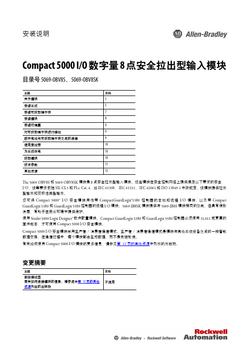
安装说明Compact 5000 I/O 数字量 8 点安全拉出型输入模块目录号 5069-OBV8S 、5069-OBV8SKThe 5069-OBV8S 和 5069-OBV8SK 模块是 8 点安全拉出型输入模块。
这些模块在安全控制网络上提供满足以下要求的安全 I/O ,该等要求包括 SIL CL3 和 PLe, Cat. 4,如 IEC 61508、IEC 61511、IEC 62061 和 ISO 13849-1 中所规定。
该模块提供拉出型输出和双极性类型输出。
您可将 Compact 5000™ I/O 安全模块用作带 CompactGuardLogix®5380 控制器的本地和远程 I/O 模块,以及带 Compact GuardLogix 5380 和 GuardLogix 5580 控制器的远程 I/O 模块。
5069-IB8SK 模块提供与 5069-IB8S 模块相同的功能,但具有保形涂层,有助于在恶劣环境中提供保护。
使用 Studio 5000 Logix Designer® 软件配置模块。
Compact GuardLogix 5380 和 GuardLogix 5580 控制器必须使用 32.011 或更高的固件版本,才可使用 Compact 5000 I/O 安全模块。
Compact 5000 I/O 安全模块采用生产者/消费者通信模式。
生产者/消费者通信模式是模块与其他系统设备之间的一种智能数据交换,在通信过程中,每个模块都会生成数据,而不是先被轮询。
有关如何使用 Compact 5000 I/O 模块的更多信息,请参见第12页的其他资源中列出的出版物。
变更摘要主题页码关于模块5安装系统5安装可拆卸端子块7安装模块8安装终端盖9对可拆卸端子块进行接线9断开电线与可拆卸端子块之间的连接9使用束线带10为系统供电10拆卸模块10技术参数11其他资源12主题页码删除接线图有关如何连接模块的信息,请参阅中第12页的其他资源列出的出版物不适用Compact 5000 I/O 数字量 8 点安全拉出型输入模块ATTENTION:Read this document and the documents listed in the Additional Resources section about installation, configuration and operation of this equipment before you install, configure, operate ormaintain this product. Users are required to familiarize themselves with installation and wiring instructions in addition to requirements of all applicable codes, laws, and standards.Activities including installation, adjustments, putting into service, use, assembly, disassembly, and maintenance are required to be carried out by suitably trained personnel in accordance with applicable code of practice.If this equipment is used in a manner not specified by the manufacturer, the protection provided by the equipment may be impaired.注意:在安装、配置、操作和维护本产品前,请阅读本文档以及“其他资源”部分列出的有关设备安装、配置和操作的相应文档。
tnc530技术手册
tnc530技术手册摘要:1.引言2.技术手册简介3.产品概述4.系统架构5.硬件组件6.软件组件7.安装与配置8.使用与操作9.维护与升级10.问题与解决方案11.附录正文:【引言】tnc530技术手册旨在为用户提供一个详细的tnc530产品技术参考,帮助用户更好地了解产品特性、使用方法以及维护技巧。
【技术手册简介】本技术手册包含了tnc530产品的详细信息,包括系统架构、硬件组件、软件组件等方面的内容,为用户提供一个全面的技术参考。
【产品概述】tnc530是一款功能强大的网络设备,适用于各种网络环境。
产品具备高性能、高可靠性、易管理等特点,满足用户对网络设备的需求。
【系统架构】tnc530采用模块化设计,分为硬件组件和软件组件两大部分。
硬件组件包括处理器、内存、存储设备等;软件组件包括操作系统、应用软件等。
【硬件组件】硬件组件方面,tnc530提供了丰富的扩展接口,用户可以根据需求选择不同的硬件模块。
同时,产品具备良好的散热性能和抗干扰能力,保证设备稳定运行。
【软件组件】软件组件方面,tnc530支持多种网络协议,提供丰富的网络功能。
此外,软件具备良好的兼容性和可定制性,满足不同用户的个性化需求。
【安装与配置】安装与配置部分详细介绍了tnc530的安装流程和配置方法,包括设备接线、初始配置、系统优化等方面的内容,帮助用户快速上手设备。
【使用与操作】使用与操作部分介绍了tnc530的基本操作方法和注意事项,包括设备启动、关闭、状态检查等方面的内容,指导用户正确使用设备。
【维护与升级】维护与升级部分为用户提供了tnc530的维护技巧和升级方法,包括故障排查、性能优化、软件升级等方面的内容,帮助用户延长设备寿命,保持设备性能。
【问题与解决方案】本部分列举了tnc530使用过程中可能遇到的问题及其解决方法,为用户在遇到问题时提供参考。
智龙 V2.0 使用手册说明书

智龙V2.0使用手册硬件篇1.1龙芯1C芯片介绍龙芯1C芯片是基于LS232处理器核的高性价比单芯片系统,可应用于指纹生物识别、物联传感等领域。
1C包含浮点处理单元,可以有效增强系统浮点数据处理能力。
1C的内存接口,支持多种类型的内存,允许灵活的系统设计。
支持8-bit SLC NAND和MLC NAND FLASH,提供高容量的存储扩展接口。
1C为开发者提供了丰富的外设接口及片上模块,包括Camera控制器,USB OTG2.0及USB HOST 2.0接口,AC97/I2S控制器,LCD控制器,高速SPI接口,全功能UART接口等,提供足够的计算能力和多应用的连接能力。
图1-1龙芯1C1.2智龙开发板介绍开源龙芯创客主板-“智龙”是由龙芯爱好者社区开发的一款基于国产龙芯以全开源方式推广的嵌入式最小系统主板。
具有完全开源、可手工焊接、接口丰富、本土化服务等特点。
适合物联网、智能硬件、机器人等应用和创客开发。
智龙创客主板上集成了龙芯1C SOC、网口、USB口、电源,SD卡插槽和RTC 时钟等主要部件,并提供排针接口,可通过扩展板实现更多的功能。
智龙创客主板可以运行嵌入式Linux系统和RT-Thread实时操作系统,方便用户开发,实现各种创意。
智龙创客主板是首个基于龙芯的创客开发硬件平台,与目前已有的创客开发板Arduino相比,具有性能高、网络支持好,接口丰富、可运行Linux操作系统等优势。
智龙创客主板应用领域为物联网控制、智能硬件、机器人、龙芯嵌入式教学开发,也可作为为Arduino主板的升级产品,图1-2智龙V2.0图1-3开发板正面图1-4开发板背面1.3硬件接口图1-5开发板标识图1-6开发板标识1.4串口调试连接1.3.1设置串口终端软件为了在开发板上进行相关的命令操作,需要使用交叉串口线连接开发板和主机,同时还需要在主机上使用一个串口终端软件。
如果主机的系统是Windows操作系统,可以使用SecureCRT或者超级终端。
W5300控制器详细设计及使用说明文档
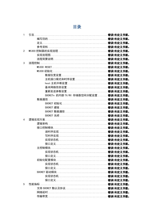
目录1 引言......................................................错误!未定义书签。
编写目的............................................错误!未定义书签。
定义................................................错误!未定义书签。
参考资料............................................错误!未定义书签。
2 W5300控制器的实现流程....................................错误!未定义书签。
实现流程图..........................................错误!未定义书签。
流程简要说明........................................错误!未定义书签。
3 流程控制..................................................错误!未定义书签。
W5300 RESET .........................................错误!未定义书签。
W5300初始化........................................错误!未定义书签。
数据位宽设置..................................错误!未定义书签。
主机接口模式和时序设置........................错误!未定义书签。
host主机中断设置.............................错误!未定义书签。
基本网络信息设置..............................错误!未定义书签。
重新发送参数设置..............................错误!未定义书签。
CM530变频器用户手册-V2.2
5.1 F0 组基本功能组..............................................................................................49 5.2 F1 组启停控制..................................................................................................55 5.3 F2 组 V/F 控制参数..........................................................................................58 5.4 F3 组矢量控制参数..........................................................................................61 5.5 F4 组电机参数..................................................................................................64 5.6 F5 组输入端子..................................................................................................65 5.7 F6 组输出端子..................................................................................................71 5.8 F7 组 辅助功能及人机界面功能....................................................................74
MC-5000系列组件兼容性指南说明书
MC-5000 SeriesComponent Compatibility GuideA list of peripheral components suitable for use with the MC-5000 series of computers2016/07/05 Version 2.0© 2016 Moxa Inc. All rights reserved.Copyright Notice©2016 Moxa Inc.All rights reserved.TrademarksThe MOXA logo is a registered trademark of Moxa Inc.All other trademarks or registered marks in this manual belong to their respective manufacturers.DisclaimerInformation in this document is subject to change without notice and does not represent a commitment on the part of Moxa.Moxa provides this document as is, without warranty of any kind, either expressed or implied, including, but not limited to, its particular purpose. Moxa reserves the right to make improvements and/or changes to this manual, or to the products and/or the programs described in this manual, at any time.Information provided in this manual is intended to be accurate and reliable. However, Moxa assumes no responsibility for its use, or for any infringements on the rights of third parties that may result from its use.This document might contain unintentional technical or typographical errors. Changes are periodically made to the information herein to correct such errors, and these changes are incorporated into new editions of the publication.Technical Support Contact Information/supportMoxa AmericasToll-free: 1-888-669-2872 Tel: +1-714-528-6777 Fax: +1-714-528-6778 Moxa China (Shanghai office) Toll-free: 800-820-5036Tel: +86-21-5258-9955Fax: +86-21-5258-5505Moxa EuropeTel: +49-89-3 70 03 99-0 Fax: +49-89-3 70 03 99-99 Moxa Asia-Pacific Tel: +886-2-8919-1230 Fax: +886-2-8919-1231Moxa IndiaTel: +91-80-4172-9088 Fax: +91-80-4132-10451. IntroductionThis document lists hardware components that are proven to provide the performance listed in the specification when used with the Moxa MC-5000 series of embedded computers, or computers that share basic design features with the MC-5000 series. Moxa computers come with multiple peripheral options and are engineered to work with components having different hardware specifications. This flexibility could sometimes lead to compatibility issues. When used with the MC-5000 series of embedded computers, peripherals from one manufacturer may not work as well as the ones made by another manufacturer. Moxa provides this list of MC-5000 series-compatible components, so that users can be certain of a reliable performance from the MC-5000 series, when used with the components listed in this document.2. Testing MethodsTo validate that a component meets the Moxa standards for quality and performance, the following five key compatibility tests are run:•Ambient temperature burn-in•Low temperature hard start•Heat/humidity burn-in•Cyclic high-low temperature burn-in•Vibration testAmbient Temperature Burn-InThe component is mounted on to an MC-5000 computer and put through a series of stress tests at an ambient temperature of around 25˚C, for a specified period of time. The duration of the test is determined based on the class of peripherals being tested.Low Temperature Hard StartThe component is mounted on to an unpowered MC-5000 computer and then the system is booted up at an extremely low temperature. The designated low temperature value depends on the computer model being tested.Heat/Humidity Burn-InThe component is mounted on to an MC-5000 computer, placed in a temperature- andhumidity-controlled enclosure, and then put through the burn-in test for a specified period of time. The temperature, humidity, and time targets vary depending on the specification of the computer model used in the test.Cyclic High-Low Temperature Burn-InThe component is mounted on to an MC-5000 computer, placed in a temperature controlled enclosure, and then put through the burn-in test wherein the temperature is cyclically varied from very high to very low and back again, over a specified period of time. The target temperature range and the duration of the test can vary depending on the specification of the computer model used in the test.Vibration TestThe component is mounted on to an MC-5000 computer that is bound inside an electromagnetic vibrator, and then put through random vibration tests along three orthogonal axes: longitudinal, transverse, and vertical. The vibration tests are compliant with the EN50155/IEC61373 vibration standards.3. Storage EnduranceStorage media, such as SSDs, CF cards, SD cards, Disk on Module, and Cfast, are composed of different electrical components. The main electrical components in these storage media, the NAND-flash memory and NAND-flash controller, impact the storage endurance and lifespan of the storage media.NAND-Flash Memory EnduranceNAND-flash memories have a limit on the number of times they can be programmed and erased (P/E). The P/E cycle as well as the erase count of a NAND-flash memory can be used to determine this limit. For example, an SLC (single-level cell) flash memory has a 60,000 P/E cycle, an MLC (multi-level cell) flash memory has a 3,000 P/E cycle, and TLC NAND flash memories have P/E cycle values up to 1,000. Each flash memory type has a different endurance level, which is why the storage lifespan is based on the flash memory type. Storage that uses SLC type flash memory could have the best endurance level compared with the MLC type storage. SLC storage usually comes with a 5-year OEM warranty (the actual warranty period depends on the original manufacturer). MLC storage only comes with a 1- to 3-year warranty. The major differences between SLC and MLC are: (a) The SLC NAND flash has a lifespan that is around 20 times that of an MLC, and (b) The price can differ by a factor of 4 to 5. The SLC type of storage is recommended for systems that are expected to have high reliability, and for applications that need to frequently write data to a storage medium.Terabytes Written (TBW)TBW is the unit used to evaluate SSD endurance. In actual applications, storage is used for routine operations and data access. Therefore the physical P/E cycle is not appropriate for describing the total rewritable data capacity. The management efficiency of the storage controller also affects thetotal rewritable data capacity result. For these reasons, Joint Electron Device Engineering Council (JEDEC) has defined a standard for SSD endurance evaluation called JESD218, which uses TBW to measure the endurance of the storage memory. By referring to this TBW value, users can easily estimate the storage specification and select a suitable storage for real-life use cases. For example, when routine operations need a maximum of 20 GB and the expected storage lifespan is 3 years, the total rewritable data demand would be 21.9 TBW (20 GB x 365 x 3). In this case, a storage that has more than 21.9 TBW will meet the requirement. We recommend selecting a storage media with a TBW that is greater than the calculated value.4. Declaration for Liability ExclusionThe specifications, warranty terms, and liability of items listed in this guide are the sole responsibility of the original manufacturers. Moxa does not take any responsibility in this regard. Please visit the manufacturers’ official websites for up-to-date product information before purchasing the components.5. Compatible ComponentsPeripheral components that have been tested and found suitable for use with the MC-5000 series of computers are listed in this section. The following table lists the Test Codes and their descriptions:Test Code DescriptionA The component has passed the ambient temperature verification testB The component has passed the low temperature verification testC The component has passed the heat/humidity verification testD The component has passed the cyclic high-low temperature verification testE The component has not been tested, but is similar to another component that has been tested in terms of its material and design.F The component has passed the vibration verification testDRAMVendor MemorySize Moxa’s PN Vendor’s PN Interface Chip Brand Speed Test Codes Apacer 2 GB N/A 75.A83E4.G010C DDR3Micron 1600 MHz A Apacer 2 GB N/A 78.A2GD9.4010C DDR3Samsung 1600 MHz A DSL 2 GB 1352110022020 D3SH56081XH18AB DDR3 Hynix 1066 MHz B, C, D DSL 2 GB 135********B0 D3SP56081XL12BAI DDR3L ProMOS 1600 MHz B, C DSL 4 GB 1352110042093 D3SS56082XH18AC DDR3Samsung 1066 MHz B, C DSL 4 GB 1352110042030 D3SH56082XH18AB DDR3Hynix 1066 MHz B, C, D InnoDisk 2 GB N/A M3SW-2GHJCC0C-E DDR3Hynix 1600 MHz B, C, D Transcend 2 GB N/A TS256MSK64V3N-I DDR3Samsung 1333 MHz E Transcend 2 GB N/A TS256MSK64V6N DDR3Samsung 1600 MHz E Transcend 4 GB N/A TS512MSK64V3N-I DDR3Samsung 1333 MHz A Transcend 4 GB N/A TS512MSK64V6N DDR3Samsung 1600 MHz A Unigen 2 GB N/A UG25U6400M8SU-ACA DDR3Hynix 1333 MHz B, C, DSSDVendor StorageSize Moxa’s PN Vendor’s PNFlashMemoryBrandFlashMemorySpecController Firmware Warranty WarrantyExclusionTestCodesApacer 64 GB N/A AP64GAS510SB N/A MLC N/A N/A 2 years Endurance > 3,000 AInnoDisk 128 GB 1352031282115 DGS25-A28D81SWAQN Micron MLC N/A N/A 2 years Endurance > 3,000B, C InnoDisk 64 GB 1352030642170 DGS25-64GD81SWAQN Micron MLC N/A N/A 2 years Endurance > 3,000B, C Memoright 32 GB N/A MRSAJ9A032GTT25C00 Toshiba MLC JMF667 MRV1.71b 3 years Endurance > 3,000B, C, D Memoright 32 GB N/A MRSAJ6C032GC125S00 Micron MLC JMF612 MRV1.1.5 3 years Endurance > 3,000 E Memoright 32 GB N/A MRSAJ6C032GC125C00 Micron MLC JMF612 MRV1.1.5 3 years Endurance > 3,000 E Memoright 60 GB N/A MRSAD4B060GC225C00 Samsung MLC N/A N/A 3 years Endurance > 3,000B, C, D Memoright 60 GB N/A MRSAD4B060GC225S00 N/A MLC N/A N/A 3 years Endurance > 3,000 E Memoright 60 GB N/A MRSAD4B060GC225S00 N/A MLC N/A N/A 3 years Endurance > 3,000 E Memoright 64 GB N/A MRSAJ6C064GC125C00 Micron MLC JMF612 MRV1.1.5 3 years Endurance > 3,000B, C, D Memoright 64 GB N/A MRSAJ6C064GC125S00 Samsung MLC N/A N/A 3 years Endurance > 3,000B, C, D Memoright 64 GB N/A MRSAJAA064GTW25C00 Toshiba MLC JMF667 MRV1.71b 3 years Endurance > 3,000B, C, D Memoright 120 GB N/A MRSAD4B120GC325S00 Micron MLC SF2281 MRV 1,50S 3 years Endurance > 3,000B, C, D Memoright 120 GB N/A MRSAD4B120GC325S00 Micron MLC SF2281 MRV 1.50S 3 years Endurance > 3,000 E Memoright 128 GB N/A MRSAJ6C128GC225S00 Micron MLC JMF612 MRV1.1.5 3 years Endurance > 3,000B, C, D Memoright 128 GB N/A MRSAJ6C128GC225C00 Micron MLC JMF612 MRV1.1.5 3 years Endurance > 3,000B, C, D Memoright 128 GB N/A MRSAJAA128GTW25C00 Toshiba MLC JMF667 MRV1.71b 3 years Endurance > 3,000B, C, D Memoright 240 GB N/A MRSAD4B240GC325S00 Micron MLC SF2281 MRV1.5.0 3 years Endurance > 3,000B, C, D Transcend 16 GB N/A TS16GSSD500 Samsung SLC JM616 120820 2 years N/A E Transcend 32 GB N/A TS32GSSD500 Samsung SLC JM616 120820 2 years N/A ETranscend 64 GB N/A TS64GSSD320 SanDisk/Micron MLC SF2281 N/A 2 years N/A E Transcend 64 GB N/A TS64GSSD500 Samsung SLC JM616 120820 2 years N/A ATranscend 128 GB N/A TS128GSSD320 SanDisk/Micron MLC SF2281 N/A 2 years N/A ETranscend 256 GB N/A TS256GSSD320 SanDisk/Micron MLC SF2281 N/A 2 years N/A AHDDVendor Size Moxa’s PN Vendor’s PN Controller Firmware Test Code HGST 500 GB N/A HTS725050A7E630 / 0J38075 N/A N/A A HGST 1 TB N/A HTS721010A9E630 / 0J22423 N/A N/A A HGST 1 TB N/A HCC541010A9E680 N/A N/A A HGST 1 TB N/A HTS541010A9E680 N/A N/A A Samsung 2 TB N/A ST2000LM003 N/A N/A A WD 750 GB N/A WD7500BPKT N/A N/A A WD 1 TB N/A WD10JUCT N/A N/A A WD 1 TB N/A WD10JPVT N/A N/A A WD 1 TB N/A WD10SPCX N/A N/A A。
ARC ARC5300-BO USB-TO-RS485 Converter 产品说明书
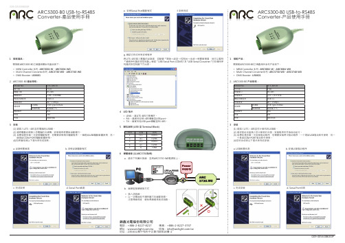
ARC5300-B0 USB-to-RS485 Converter-產品使用手冊ARC5300-B0 USB-to-RS485 Converter-产品使用手册G09-005300B000P錦鑫光電股份有限公司電話:+886-2-8227-8217 傳真:+886-2-8227-3747網址:信箱:*****************.tw 地址:235台北縣中和市中正路700號14樓-2G09-005300B000P1 搭配產品:需搭配ARC5300-B0之錦鑫相關系列產品如下 :MINI Controller 系列 : • ARC3002-W、ARC3004-W0Multi-Channel Converter系列 : • ARC3730-W0、ARC3740-W0DMX Booster :• US66012. ARC5300-B0產品規格:3 安裝(1) 請插入UTS – 485至您電腦的USB端。
(2) 請將驅動光碟插入您電腦的光碟機。
安裝程序將開始自動運行。
(3) 如果這是您第一次安裝驅動程序,您需要安裝兩次驅動程序。
一個是給USB驅動軟體使用,另一 個是給COM PORT驅動軟體使用。
(4)您將會依照以下提示來完成安裝 :a. USB裝置偵測c. 完成安裝1 搭配产品:需搭配ARC5300-B0之锦鑫相关系列产品如下 :MINI Controller 系列 : • ARC3002-W、ARC3004-W0Multi-Channel Converter系列 : • ARC3730-W0、ARC3740-W0DMX Booster :• US66012. ARC5300-B0产品规格:3 安装(1) 请插入UTS – 485至您计算机的USB端。
(2) 请将驱动光盘插入您计算机的光驱。
安装程序将开始自动运行。
(3) 如果这是您第一次安装驱动程序,您需要安装两次驱动程序。
一个是给USB驱动软件使用,另一 个是给COM PORT驱动软件使用。
- 1、下载文档前请自行甄别文档内容的完整性,平台不提供额外的编辑、内容补充、找答案等附加服务。
- 2、"仅部分预览"的文档,不可在线预览部分如存在完整性等问题,可反馈申请退款(可完整预览的文档不适用该条件!)。
- 3、如文档侵犯您的权益,请联系客服反馈,我们会尽快为您处理(人工客服工作时间:9:00-18:30)。
C5300 模块硬件接口手册_V2.0
共 41 页 第 1 页
重要声明
版权声明 版权所有:龙尚科技(上海)有限公司 本资料及其包含的所有内容为龙尚科技(上海)有限公司所有,受中国法律及适 用之国际公约中有关著作权法律的保护。未经龙尚科技(上海)有限公司书面授 权,任何人不得以任何形式复制、传播、散布、改动或以其它方式使用本资料的 部分或全部内容,违者将被依法追究责任。
2. 产品简介...................................................................................................................................10 2.1. 特性列表.......................................................................................................................11 2.2. C5300 模块工作模式 .................................................................................................12 2.3. 系统功能框图...............................................................................................................13 2.4. 硬件接口.......................................................................................................................14
免责声明 本公司不承担由于客户不正常操作造成的财产未声明之前,本公司有权根据技 术发展的需要对本手册内容进行更改,且更改版本不另行通知。
C5300 模块硬件接口手册_V2.0
共 41 页 第 2 页
目录
1. 引言.............................................................................................................................................7 1.1. 文档目的.........................................................................................................................7 1.2. 内容一览.........................................................................................................................7 1.3. 相关文档.........................................................................................................................7 1.4. 修订记录.........................................................................................................................8 1.5. 缩略语.............................................................................................................................8
3. 应用接口及功能描述...............................................................................................................16 3.1.PCI express Mini Card接口定义.............................................................................16 3.2. 电源...............................................................................................................................17 3.2.1. 电源接口描述及外围电路设计.......................................................................18 3.2.1.1. VBAT输入.............................................................................................18 3.2.1.4. RESET输入 ..........................................................................................18 3.2.2. 开关机控制.......................................................................................................19 3.2.2.1. 上电开机...............................................................................................19 3.2.2.2. 掉电关机...............................................................................................19 3.2.3. 复位控制...........................................................................................................20 3.3. USB接口.......................................................................................................................20 3.3.1. USB接口描述 ...................................................................................................20 3.3.2. USB参考电路 ...................................................................................................21 3.3.3. USB驱动...........................................................................................................21 3.3.3.1. Linux系统加载C5300 的USB驱动过程...........................................22 3.3.3.2. Linux系统下C5300 交互AT过程......................................................24 3.3.3.3. Linux系统下C5300 拨号上网过程...................................................25 3.4. RUIM/UIM接口...........................................................................................................28 3.4.1. RUIM/UIM卡接口描述...................................................................................28 3.4.2. RUIM/UIM卡接口参考设计...........................................................................28 3.5. PWM输出接口..............................................................................................................30 3.5.1. PWM输出信号描述..........................................................................................30 3.5.2. Netlight参考电路............................................................................................31 3.6. 飞行模式控制接口.......................................................................................................31 3.6.1. 按键控制...........................................................................................................31 3.6.2. AT指令控制 ......................................................................................................31 3.7. GPIO接口.....................................................................................................................32 3.8. 天线接口.......................................................................................................................32 3.8.1. 天线的安装.......................................................................................................32