博世BOSE-FS4400使用安装说明
BOSEfex音箱使用说明

BOSEfex音箱使用说明
必须加个功放(功率放大器)或变压器。
功率,阻抗要与BOSEfex 音箱背面标识的参数匹配,且功放或变压器的额定输出功率要大于音箱额定功率的1.5倍。
连接方法:
1、BOSEfex红、黑接口与功放或变压器功率输出端子连接。
红接红(正接正),黑接黑(负接负)。
必须一致,不可反接。
连接线为音箱连接专用银/铜线材。
2、连接完毕后,可以把电脑或电视的音频信号(AUDIO/LINE OUT)输出给功放或变压器的输入口(LINE/AUX IN)。
连接线为3.5mm插头对双莲花音频线,或3.5mm对双6.5mm插头音频线。
根据插口选择连接线。
3.5mm插在电脑绿色插口,双莲花或6.5mm 插头插在功放信号输入端上。
连接过程中不可开启功放、变压器电源,一切连接完成后方可开启电源,慢慢旋转音量增大响度。
通过蓝牙配对功能进行连接。
具体百连接方法如度下:
1. 手机或者问平板打开蓝牙功能,进去搜索蓝牙耳机状态。
2. 使无线蓝答牙音箱在开专机状态,需要长按无线蓝牙音箱的接听键。
3. 直到指示灯属:蓝灯红灯交替闪烁再松开。
4. 这个时候蓝牙音箱和手机或者平板就会进入匹对。
博世安保 vip xd 网络视频服务器 快速安装指南说明书

VIP XD | 快速安装指南中文 | 2VIP XD 的基本版。
图形中所示的 VIP XD 音频版代表所有版本。
博世安保有限公司 | 2006-05 | V2.0VIP XD | 快速安装指南中文 | 3交货项目z VIP XD 网络视频服务器,基本版或音频版z带四个主适配器的电源插座z配置电缆z光盘z快速安装指南博世安保有限公司 | 2006-05 | V2.0博世安保有限公司 | 2006-05 | V2.0VIP XD | 快速安装指南中文 | 41. 拆开包装箱z请检查交货项目是否齐全且完好无损。
z如果发现任何损坏,请将您的装置交由博世安保有限公司检查!博世安保有限公司 | 2006-05 | V2.0VIP XD | 快速安装指南中文 | 52. 连接监视器z 用 Video Out 插孔连接模拟监视器,或者用 VGA 插孔连接 VGA监视器。
博世安保有限公司 | 2006-05 | V2.0VIP XD | 快速安装指南中文 | 63. 连接音频组件(仅限音频版)z使用插孔连接音频线路。
z将话筒和扬声器连接至相应的接线端子。
博世安保有限公司 | 2006-05 | V2.0VIP XD | 快速安装指南中文 | 74. 连接串行接头z 如果装置需要一个串行连接,请将配置电缆的自由端连接至已连接在电源插座上的弹簧夹接头。
z 将弹簧夹接头连接至装置上的橙色插座。
z将配置电缆连接至计算机的串行接口。
博世安保有限公司 | 2006-05 | V2.0VIP XD | 快速安装指南中文 | 85. 连接报警开关和继电器线路z将报警开关连接至相应的接线端子。
z将继电器线路连接至相应的接线端子。
博世安保有限公司 | 2006-05 | V2.0VIP XD | 快速安装指南中文 | 96. 连接至网络z通过 ETH 插座将装置连接至网络。
z请确保电源插座附带了正确的主适配器,然后将其插入合适的主电源插座。
博世欧洲精英使用手册
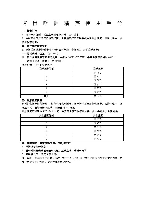
博世欧洲精英使用手册一、设备打开1.按下锅炉控制面板左上角的电源开关,运行设备;2.控制面板下方的运行指示灯亮,温度指示灯显示采暖或生活热水温度。
燃烧过程中,燃烧器指示灯亮。
二、打开集中供热功能1.旋转采暖温度控制按钮(控制面板左边一个按钮),调节采暖温度:——地板采暖:位置2(约50℃)。
注:初次使用温度不宜调的太高,一般在20至30℃即可。
最高温度不得超过60℃。
——散热片系统:位置6(约80℃).利用热水温度调节按钮,,调节生活热水温度。
温度指示不显示热水温度,加热过程中,温度显示灭,当燃烧器点燃后,燃烧器指示灯亮起。
热水温度可设置在40℃-60℃之间,单实际温度取决于热水量,热水量越大,温度越低。
1.保持设备打开状态。
2.逆时针旋转采暖温度控制按钮,至最左端。
采暖泵关闭。
3.夏季模式下,温度指示关闭。
注:当压力表水压低于正常水压时,应打开补水阀补水,直到水压压力处于正常范围内。
然后一定要关闭补水阀,否则会造成锅炉泄水。
五、故障代码博世欧洲之星操作手册一、设备打开1.首先确认燃气阀门已经打开,锅炉电源插头已插上;2.按下锅炉控制面板左上角的电源开关,运行设备;3.显示屏上显示采暖的出水温度二、试运行:1.打开系统散热片的所有阀门;2.打开补水阀,生活冷水阀,注水至1到2巴的压力,然后关闭冷水阀3.散热片排气;4.打开冷水阀,将系统压力重新充注到1-2巴5.打开燃气阀三、打开集中供热功能1.热水温度可设置在45℃至82℃之间;2.若为地板采暖系统,采暖温度不得高于60℃;3.旋转控制面板左下角的采暖控制旋钮,调节采暖温度;(初次使用时不宜调太高)4.采暖类型不同,最大采暖出水温度设置不同:——地板采暖系统:2档(约50℃)1.调节锅炉控制面板右下角的生活热水温度调节旋钮来设置生活热水温度;2.显示屏上显示的仍是采暖出水温度3.生活热水温度可在40℃和60℃之间设置。
但水龙头的世界出水温度取决于进水量的大小,进水量越大,温度越低。
博世BOSE-FS4400使用安装说明

Bose ControlSpace ESP-00 Dante 网络卡安装指南说明书

WARNING:This product is intended for installation by professional installers only.CAUTION: Make no modification to the system or accessories. Unauthorized alterations may compromise safety, regulatory compliance, and system performance.CAUTION: Electro-Static Discharge (ESD) sensitive device. Handle with care.Note: The ControlSpace ESP-00 Dante™ network is compatible with ESP-00 Series II, ESP-00 (PC 315228), and ESP-88 (PC 313419) processors.Thank you for selecting the Bose® ESP-00 Series II engineered sound processor. This document is intended to provide professional installers with basic installation and safety guidelines for installing the optional Dante card into a Bose ESP processor. Please read this document before attempting installation.The Dante card provides audio connectivity with any device designed for Dante networking. This card is capable of receiving up to 16 audio streams and transmitting up to 16 audio streams.For further details on network best practices, how to use Dante Controller and how to interface PCs and Macs using Dante Virtual Soundcard, visit .Additional input channel routing, setup, and monitoring is possible using Bose® ControlSpace® Designer™ software, available from .T o install the Dante card into an ESP-00 II processor, follow these instructions:1. Turn off and unplug the ESP processor.2. Detach the top cover by removing the 8 cover screws.3. Remove and save the two screws from an available expansion card blank panel.4. Align the card’s four front-facing LEDs with the holes in the front of the chassis, and ensure the connector on the side of the card isaligned with the connector on the motherboard. Use the black guide on the bottom of the case to direct the card using the grooves.(See Figure 1.)5. When the connector on the card is aligned above the connector on the motherboard, press gently to mate the connectors.(See Figure 2.)6. Screw the card into place using the two screws from the blank panel.7. Reattach the top cover and fasten the 8 screws.8. Plug in the power supply and turn on the ESP processor.2.Figure 1. Figure。
4400系列电源包安装和操作说明书
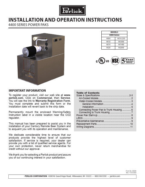
PERLICK CORPORATION 8300 W. Good Hope Road, Milwaukee, WI 53223 • 800.558.5592 • MODELS 4400 Series 44044414-23044104410W 44144414W 44204420WCUSINSTALLATION AND OPERATION INSTRUCTIONS4400 SERIES POWER PAKSIMPORTANT INFORMATIONTo register your product, visit our web site at . Click on Commercial , then Service . You will see the link to Warranty Registration Form . You must complete and submit this form or the installation date will revert back to the ship date.Permanently mount the enclosed Warning/Safety Instruction label in a visible location near the CO2 regulator.This manual has been prepared to assist you in the installation of your Century Remote Beer System and to acquaint you with its operation and maintenance. We dedicate considerable time to ensure that our products provide the highest level of customer satisfaction. If service is required, your dealer can provide you with a list of qualified service agents. For your own protection, never return merchandise for credit without our approval.We thank you for selecting a Perlick product and assure you of our continuing interest in your satisfaction.Table of ContentsSizes & Specifications ............................................2-3 Air-Cooled Models .................................................2 Water-Cooled Models ............................................3 General Information ..........................................4 Installation ........................................................5 Connecting Power Pak to Trunk Housing ..............6 Connecting to Trunk Housing ................................7Power Pak Start-Up ...................................................8LEDS .........................................................................9Preventative Maintenance .........................................9Replacement Parts ..................................................10Wiring Diagrams (11)Form No. Z2020Rev. 11.30.2022(Ground, Neutral, Hot-Power, Hot-Power)AC: 115 - 208/240v, 60 HZ, Split Single PhaseC US(Ground, Neutral, Hot-Power, Hot-Power)AC: 115 - 208/240v, 60 HZ, Split Single PhaseCUSPRODUCT DESCRIPTIONPower Paks have always been an integral part of a Perlick Century Beer System. The 4400 Series Power Pak product line has been expanded to satify longer beer runs. A Power Pak circulates coolant solution (food grade propylene glycol with distilled water) fromwalk-in cooler to the dispensing station(s) and back,maintaining the desired dispensing temperature at the faucet. The 4400 series Power Pak incorporate a 1/3 hp ball bearing, maintenance free motor with a 100 gallon per hour 150 psig positive displacement pump for optimum performance. The 4400 series Power Pak product line employs a direct expansion form of refrigeration increasing the units’ efficency aswell as making the units more compact. These unitsalso employ an electronic temperature control with digital readout. This state of the art control controlsthe performance of the unit as well as giving theuser a visual indication of the how the unit is workingas well as giving the user a visual indication of the how the unit is working as well as early indication if something may be going wrong through the use of internal alarms.AccessoriesPower Cord KitC2296A-20--12/3 Cord, 20A, Nema Plug 5-20P, Dedicated Circuit Models - See above electrical specificationsPower Pak Racks61790, 61790+1, 61790+2 - All ModelsPower Pak Wall Mounting BracketsFor Models 4404 & 4410 onlyCoolant Solution-63299-1One gallon Perlick Coolant solution, 30% DowFrost HD/70% Distilled Water Coolant Connector Kit 63335 - All Models Leg Set - All Models57782 . . . Set of four, 5 3/4”-71/2” adjustable legsPump Kits4430 - Pump kit, 115V, 6.1 A, 100 gph, 130 psigModels 4410, 4410W4431 - Pump kit, 115V, 5.6 A, 100 gph, 130 psig Models 4414, 4414W4432 - Pump kit, 230V, 2.8 A, 100 gph, 130 psig Models 4414-230, 4420WARNING: California Prop 65 NoticeThese products may expose you to chemicals i ncluding Chromium, which are known to t he state of California to cause cancer and b irth defects or other reproductive harm. For more information on whether a product in this list contains these chemicals, please refer to the specific product page at . Or to find out more about Prop 65, go to .4400 SERIES POWER PAKS - INSTALLATIONOperation/Installation ManualINSTALLATIONIMPORTANT SAFETY WARNINGS!• Follow all National and Regional Codes.• Read Installation and Operating Instructions carefully before attempting to install, operate or maintain the product.• Protect yourself and others by observing all safety information.• Electrical hazards exist and can cause injuries if not serviced by properly trained personnel.• Failure to comply with instructions could result in personal injury and/or property damage!• Retain instructions for future reference.• Never operate the circulating pump without coolant in the reservoir.NOTE: Air-cooled Power Paks must be installedin areas with adequate ventilation to maintain ambient temperatures of less than 105°F to achieve optimum performance and satisfy warranty requirements.INSTALLING THE POWER PAKPrior to installing a 4400 Series Power Pak, it isimperative that the method of connecting it to theelectrical service has been determined. Ensure thatthe electrical service to power the Power Pak willhandle the load requirements. Perlick has a PowerCord specifically designed for a Power Pak, which has a RLA of 16 amps or less, and a MCA of 20 amps orless. All units with RLA greater than 16 amps and aMCA of greater than 20 amps should have the Power Pak hard-wired to electrical service.ALL MODELS• Determine the ideal placement of the Power Pak.Locate the connection point to the truck housingand place the Power Pak as close to this point aspossible. NOTE: If the Power Pak is to be located on top of the walk-in cooler, it is imperativethat proper ventilation is provided to preventsystem failure due to overheating. Inadequateventilation will void warranty.• Place the Power Pak and Ensure that it is level to provide proper overflow protection. REMINDER: Allow a minimun of six inches of clearace on the louvered ends of the cabinet for proper airflow. Allow accessibility room on the top of the cabinet for serviceability.• Remove the top panels (2).• Ensure Power Switches for Condensing Unit and Pump(s) are in the OFF position. Make the electrical connections per ther illustrations. NOTE: Electrical circuit shold be a dedicated circuit for use only with the Power Pak. The circuit should be sized in accordance with the electrical requirements of each unit as well as in compliance with all National and Local Codes.• Plumb overflow port to a suitable reservior/drain.WATER-COOLED MODELS• In addition to the above installation instruction:• Care should be exercised in locating the PowerPak so that the unit will never be exposed to temperatures below freezing.• If the Power Pak is installing more than 5 feet higher than the remote outlet drain point (i.e., location of the floor drain) of the condenser, a vacuum breaker or open vent line should be provided to prevent the discharge line from creating a partial vacuum condition in the condenser water system.• If a water-circulating pump is used it should beplaced on the water supply side of the condenser, so water is being pushed through the condenser.• A potable water supply is required aswell as a drain or reclamation system. Make water supply connection to fitting labeled as the water inlet. Make outlet connection to fitting labeled as the water outlet connection. Both the inlet and outlet fittings supplied with the Power Pak are 1/2” Quick Connect fittings.• This equipment when equipped with a water-cooledcondenser, connected to a portable water supply system is to be installed with adequate backflow protection to comply with applicable federal, state and local codes.(Backflow protection not included.)CONNECTING POWER PAK TO TRUNK HOUSING 400 Series Power Paks require rigid fittings with a minimum pressure rating of 150 psig. Use Coolant Connector Kit #63335 to connect Power Pak to Trunk Housing.• Inspect pump outlet port for debris. Insert barbed fitting #63307 into pummp outlet port.• Inspect Glycol Return Manifold inlet for debris.Insert barbed fitting #63307 into return manifold inlet port.• Cut supplied coolant tubing, #54588, to required length to reach from Power Pak to Trunk Housing connection point.• Cut tubular insulation sleeve, #C12700, in half and install over previously cut coolant tubing.• Take Oetiker clamps, #54871-210, and install over coolant tubing ends.• Push coolant lines, one each over pump outlet barbed fitting #63307 and return manifold barbed fitting #63307.• Position Oetikers over barbed fitting and clamp securely.• Slide tubular insulation sleeves tightly against connection points. Use insulation tape as necessary to ensure an air tight seal to prevent excessive heat gain or condensation problems.• Drill a 3-1/2” diameter hole in walk-in cooler to accommodate coolant lines.• Install insulation donuts over hole (both inside and outside of cooler walls.• Slide large insulation sleeve, #57478, over remaining coolant tubing exposed to warm air conditions including inside walk-in cooler from Power Pak to Trunk Housing connection point. Seal and tape all seams to prevent excessive heat gain or condensation problems.• Slide coolant lines through 3-1/2” donut hole previosly cut in walk-in cooler wall.• Position Trunk Housing coolant lines and Coolant Connector kit lines in horizontal position, to alleviate condensation runoff into Trunk Housing.• Cut Trunk Housing coolant lines with tubing cutter to ensure clean burr free ends.• Take Oetikers clamps #54871-210, and install over coolant connector kit tubing ends.• Slide coolant connector kit tubing over the trunk housing coolant lines and secure using the Oetikers.• Complete the insulation process by ensuring that all coolant lines are well insulated including all seams to prevent excessive condensation and heat gain.• Seal donut hole to ensure an air tight seal to prevent walk-in cooler problems as well as condensation. CONNECTING TRUNK HOUSING COOLANT LINES TO DISPENSING HEAD• Position the trunk housing so that beverage lines can be connected with a minimum cutting.• Split trunk housing approximately 12 inches from the end to allow working room for the connections.• Cut and deburr copper coolant lines coming from trunk housing and dispensing head. Stagger the lengths.• Connect trunk housing coolant lines to dispensing head coolant lines using clamps, hose and 3/8”x 1/2” union, included in Head connecting kit, #63486. Ensure that coolant lines are fully clample to guarantee a leak free connection.SYSTEM START-UPUse only Perlick Approved Coolant Solution, #63299-1, all other solutions and mixtures will void the Perlick warranty. The Coolant Solution has been pre-mixed for optimum performance and wear protection. The Power Pak resevoir holds approximately 1.75 gallons of solu-tion. It takes approximately 1 gallon of Coolant Solution to fill every 60 feet of Perlick Trunk Housing.• Never operate the circulating pumps without coolant in the resevoir.• Fill Power Pak resevoir with Perlick Coolant Solution.• Turn condensing unit switch and pump switch to the ON position. Coolant solution level will begin to drop in resevoir.• Continue adding Perlick Coolant Solution until no air bubbles are apparent from the Coolant return line. NOTE: Never allow for the Coolant level in the resevoir to drop below the heat exchanger tube inlet. Allowing the level to drop below the inlet will allow air into the lines.• Fill Power Pak reservoir until both the return line fitting port and the overflow tube port are submersed under Coolant Solution. Watch return line fitting port for additional Coolant Solution may need to be added.• Thoroughly check all field connection points for leaks.• Monitor Power Pak Temperature read-out to ensure Power Pak is working properly. Dependent on length of trunk housing run(s) and surrounding ambient conditions, these factors will determine how long it takes for the Power Pak to cut-out on the temperature control. DIGITAL TEMPERATURE CONTROLLERThe 4400 Series Power Pak comes equipped with a Factory Programmed Electronic Thermostat with display. The Thermostat has numerous factory settings, which should never be adjusted or tampered with to ensure proper operation of the Power Pak. The Thermostat has been factory programmed to cut-out at 30°F with a hysteresis/differential of 4°F.Front Panel Commands–Normal OperationSET:To display target set point.DEFROST:To start a manual defrost. (This feature is avail-able, however, the parameters for actuation are pro-grammed, such that, no defrost is available).Front Panel Commands–Programming Mode SET:Selects a parameter or confirms an operation.UP ARROW:Browses the parameter codes or increases the dis-played value.DOWN ARROW:Browses the parameter codes or decreases the dis-played value.Meaning of LEDSLED MODE FUNCTION SNOWFLAKE ON CompressorEnabled SNOWFLAKE FLASHING Programing Phase (flashingwith DEFROST) Anti-short cycledelay enabled DEFROST FLASHING Programming Phase (flashingwith SNOWFLAKE) Drip time inprogress DISPLAY MESSAGE MEANINGSMESSAGE MEANINGPOF Keyboard is locked out. Noparameters can be adjustedwithout unlocking the keyboard. ALARM MEANING ACTIONEE Data or Consult Factorymemory failureP1 Room probe Numerous - seefailure note 1NOTE 1: Faulty probe, loose connection, broket wire. (Power Pak will continue to operate with a faulty probe. The controller has been factory programmed to continue operation with the compressor cycling on and off in 5 minute intervals.How to see the SETPOINT• Press and immediately release the SET key: the display will show the Set point value.• Press and immediately release the SET key or wait for 5 seconds to display the probe value again. How to change the SETPOINT• Press and hold the SET key for more than 2 seconds to change the Set point value.• The value of the set point will be displayed and the SNOWFLAKE LED starts blinking.• To change the Set value, press the UP or DOWN ARROWS, dependent on the new set point value.• To memorize the new set point value, press the SET key again or wait 15 seconds.WARNING:IF MESSAGE OR INFORMATION SHOWN ON READOUT IS UNFAMILIAR, ALLOW CONTROL TO SIT FOR A MINIMUN OF 15 SECONDS AND CONTROLLER SHOULD RETURN TO DISPLAY PROBE TEMPERATURE.Perlick is committed to continuous improvement. Therefore, we reserve the right to change specifications without prior notice11Form No. Z2020Rev. 11.30.2022Wiring Diagram For 414-230, 4420, AC115 - 208/240, 60 HZ Power Paks (4 Wire AC Power Source Required)Wiring Diagram For 4404, 4410, 4414 115V Power PaksForm No. Z2020Rev. 11.30.2022 PERLICK CORPORATION 8300 W. Good Hope Road, Milwaukee, WI 53223 • 800.558.5592 • 。
博斯免空气DS 16SE、40SE或100SE音响系统的铝制网格安装指南说明书
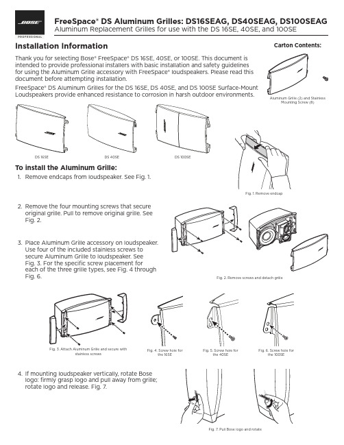
Installation InformationThank you for selecting Bose® FreeSpace® DS 16SE, 40SE, or 100SE. This document is intended to provide professional installers with basic installation and safety guidelines for using the Aluminum Grille accessory with FreeSpace® loudspeakers. Please read this document before attempting installation.FreeSpace® DS Aluminum Grilles for the DS 16SE, DS 40SE, and DS 100SE Surface-Mount Loudspeakers provide enhanced resistance to corrosion in harsh outdoor environments.To install the Aluminum Grille:1.2. Fig. 2.3. Use four of the included stainless screws to secure Aluminum Grille to loudspeaker. See Fig. 3. For the specific screw placement forFig. 6.4. rotate logo and release. Fig. 7.Fig. 3. Attach Aluminum Grille and secure withstainless screwsDS 16SE DS 40SE Aluminum Grille (2) and StainlessCarton Contents:©2017 Bose Corporation. All rights reserved.Framingham, MA 01701-9168 USA,All trademarks are the property of their respective ownersAM799275 Rev. 00July 2017Safety InformationCAUTION: This product is intended for installation by professional installers only! PRECAUCIÓN: Solo un instalador profesional deberá montar este producto!ATTENTION: L’installation de ce produit est réservée à un technicien professionnel! ACHTUNG: Dieses Produkt darf nur von fachkundigen Monteuren installiert werden!CAUTION: Make no modification to system or accessories. Unauthorized alterations may compromise safety, regulatory compliance, and system performance.PRECAUCIÓN: No realice alteraciones no autorizadas a este producto; esto podría comprometer la seguridad, el cumplimiento de las normas y el rendimiento del sistema.ATTENTION: Ne pas faire des modifications non autorisées à ce produit; ce qui pourrait compromettre la sécurité, la conformité réglementaire et la performance du système.ACHTUNG: Keine nicht autorisierten Veränderungen am Produkt vornehmen. Diese können die Sicherheit, die Einhaltung von Richtlinien und die Systemleistung beeinträchtigen.CAUTION: This accessory is for use with Bose FreeSpace® DS 16SE, 40SE, and 100SE only.PRECAUCIÓN: Este accesorio está diseñado para usarse únicamente con altavoces Bose FreeSpace® DS 16SE, 40SE, and 100SE.ATTENTION: Cet accessoire est destiné pour l’usage avec les haut-parleurs Bose FreeSpace® DS 16SE, 40SE, and 100SE exclusivement. ACHTUNG: Dieses Zubehör ist ausschließlich zur Verwendung mit Bose FreeSpace® DS 16SE, 40SE, and 100SE Lautsprechern vorgesehen.CAUTION: Only use the mounting hardware supplied with this product.PRECAUCIÓN: Use solo el equipamiento de montaje provisto con el producto.ATTENTION: Utilisez uniquement les accessoires de montage fournis avec ce produit. ACHTUNG:Verwenden Sie nur die mit diesem Produkt mitgelieferten Befestigungsmittel.Importer InformationEuropean UnionBose Products B.V ., Gorslaan 60, 1441 RG Purmerend, The Netherlands ChinaBose Electronics (Shanghai) Company Limited, Part C, Plan 9, No. 353 North Riying Road, China (Shanghai) Pilot Free Trade Zone TaiwanBose T aiwan Branch, 9F-A1, No. 10, Section 3, Minsheng East Road, T aipei City 104, T aiwan T el: 886 2 2514 7977MexicoBose de México, S. de R.L. de C.V ., Paseo de las Palmas 405-204, Lomas de Chapultepec, 11000 México, D.F. T el: 001 800 900 2673Additional InformationFor additional information on FreeSpace® loudspeaker modules and accessories, refer to the installation guide available at . T o request a printed copy, use the phone numbers provided.Contact InformationBose CorporationFramingham, MA 01701 USA Corporate Center: 508-879-7330 Americas Professional Systems, T echnical Support: 800-994-2673Limited WarrantyYour product is covered by a limited warranty. Visit for warranty details.The warranty information provided with this product does not apply in Australian and New Zealand. See our website at/au/warranty or /nz/warranty for details of the Australian and New Zealand warranty.。
BOSCH Sicherheitssysteme GmbH(3)操作文件 2019版说明书

使用帮助 查找信息 打印帮助 简介 系统概述 硬件要求 软件要求 许可证要求 概念 BVMS设计理念 单个Management Server系统 Enterprise System Server Lookup Unmanaged site 自动网络补偿(ANR) 报警处理 兴趣区域(ROI) Intelligent Tracking 非活动注销 故障继电器 文本数据 脱机Operator Client 在脱机模式下进行工作 不指定版本的Operator Client 在兼容模式下工作 全景摄像机的查看模式 360度全景摄像机 - 适合安装在地板或天花板上 180度全景摄像机 - 适合安装在地板或天花板上 360度全景摄像机 - 适合安装在墙壁上 180度全景摄像机 - 适合安装在墙壁上 全景摄像机的裁剪视图 验证真实性 SSH数据通道 使用入门 启动 Operator Client 接受新配置 访问系统 使用 Server Lookup 显示摄像机图像 选择时区 在图像窗格中显示摄像机 显示全景摄像机 切换全景摄像机的查看模式 显示双重热成像/光学摄像机 显示多个 Management Server 的摄像机 在逻辑树中查找项目 更改图像窗格行数 排列图像窗格并调整其大小
使用联机帮助时,您可以随时从浏览器窗口中打印帮助主题和信息。 要打印帮助主题: 1. 右击右窗格,选择打印。
此时会打开打印对话框。 2. 单击打印。 P 主题会在指定的打印机上打印出来。
2019.08 | V 1 | Operator Client
操作手册
Bosch Sicherheitssysteme GmbH
2019.08 | V 1 | Operator Client
6 zh-CHS | 目录
14.3.5 14.4 14.4.1 14.4.2 14.4.3 14.4.4 15 15.1 15.2 15.3 15.4 15.5 15.6 15.7 15.8 15.9 15.10 15.11 15.12 15.13 15.14 15.14.1 15.14.2 15.14.3 15.14.4 15.15 15.16 15.17 15.18 15.19 15.20 15.21 15.22 15.23 15.24 15.25 15.26 15.27 15.28 15.29 15.30 15.31 15.32 15.33 15.34 15.35 15.36 15.37 15.38
博士汽缸泵SP系列产品安装说明书

This document and other information from Parker Hannifin Corporation, its subsidiaries and authorized distributors provide product and/or system options for further investigation by users having technical expertise. It is important that you analyze all aspects of your application, including consequences of any failure, and review the information concerning the product or system in the current product catalog. Due to the variety of operating conditions and applications for these products or systems, the user, through its own analysis and testing, is solely responsible for making the final selection of the products and systems and assuring that all performance, safety and warning requirements of the application are met.
BOSELINK的使用及配件方式
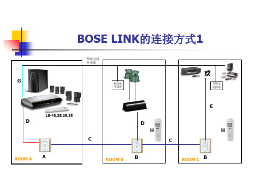
33948 33949
DUAL SOURCE/DESTINATION PLATE WHITE DUAL SOURCE/DESTINATION PLATE IVORY
双音源/终端面板,白色 双音源/终端面板,象牙色
34523 34524 35899 35901 35902 35903
BOSE SYSEM CABLE II 150M BOSE SYSEM CABLE II 300M BOSE LINK A CABLE BLACE 0.6M BOSE LINK A CABLE WHITE 2M BOSE LINK B SOURCE CABLE WHITE 2M BOSE LINK B CONNECTION CABLE BLACK 15M
价格 100 100 230 230 3500 6000 70 100 100 280 280
140
35324
PERSONAL MUSIC CENTRE II
个人音乐中心
1500
H
ROOM D
E
E
有线电 视插座
H
ROOM E
代码 A B C D E F
G H
编码
产品名称
Hale Waihona Puke 产品名称描述34247 34278
SINGLE SOURCE/DESTINATION PLATE WHITE SINGLE SOURCE/DESTINATION PLATE IVORY
单音源/终端面板,白色 单音源/终端面板,象牙色
BOSE LINK的连接方式1
75欧有线 电视线
G
有线电
视插座
或
有线电 视插座
LS-48.38.28.18
D
ROOM A
博世Bosch Motorsport ABS M4 Porsche Cup 安装说明书
6 / 22
Fig. 6: Original Cup parts removed
For the installation of the ABS HU assembly, push it into the rubber bushes as shown in the picture below.
ABS M4 Porsche Cup Installation Instructions
Mounting of the yaw rate sensor E to the mounting plate F.
4 x Screw M3 x min 10mm with nut, not Screws to mount the diagnostic con‐
shown
nector to the fuse holder M and to
8 / 22
ABS M4 Porsche Cup Installation Instructions
Bosch Motorsport
Installation of the front wiring loom | 4
4 Installation of the front wiring loom
Bosch Motorsport
Fig. 8: Brake pipes connected
Screw the dummy plug (item I) into the free hole of the connector for the rear axle. Fill the ABS brake pressure sensor with brake fluid to avoid air in the system. Use a syringe. Install the ABS brake pressure sensor in the left bore (view from the front) of the front axle connector.
博世bosch安装指南LTC 0440数字设备 cameras EN 中文说明书
Installation ManualDigital Color Cameras ENInstallatiehandleidingDigitale Kleurencamera NLSPECIFICACIONESDescripción general de los modelosL TC 0440/x0 Alta resoluciónEstándarPAL NTSC Píxeles activos (H x V)752 x 582768 x 494Convertidor de imagen 1/3" CCD interlinealResolución 480 líneas de TV Iluminación mínima <0.4 lux (30 IRE)Relación señal/ruido > 50 dB Salida de vídeo 1 Vpp, 75 ohmSincronización Interna o bloqueo de línea (seleccionable)Obturador Automático / Sin parpadeo / Desactivado (seleccionable)PAL: 1/50 - 1/125000 - NTSC: 1/60 - 1/150000AGC Encendido (0-21 dB)/ Apagado (0 dB) (seleccionable)BLC Encendido/apagado (seleccionable)ATWAutomático de 2.500 a 9.000 K (con modo 'Hold'(mantener))Montura lentes Compatible con C y CSALCIris de vídeo o iris de tipo DC (detección automática)Fuente de alimentación L TC 0440/10 y /20: 12 a 28 Vc.a. u 11 a 36 Vc.c.L TC 0440/50 y /60: 100 a 230 Vc.a.Consumo de energía <4 WDimensiones (Al x An x L) 58 x 66 x 122 mm (2,28 x 2,6 x 4,8 pulgadas sin lente)Peso450 g (sin lente)Montaje de trípode Dos 1/4" 20 UNC, aislado (inferior) y no aislado (superior).T emperatura defuncionamiento De -20°C a +50°CMandosVisualización en pantalla (OSD) con controles de teclasprogramablesBaja tensiónAlta tensiónPAL (Europe)NTSC (USA)PAL (Europe)NTSC (USA)L TC 0440/10L TC 0440/20L TC 0440/50L TC 0440/60DESEMBALAJEDesembale el equipo y manipúlelo con cuidado. El embalaje contiene:•Una cámara•Tapa de protección CCD•Conector de lente de repuesto (macho)•Estas instruccionesNota:Si el equipo se ha dañado durante el transporte, colóquelo en el embalaje original y notifíquelo al transportista o al distribuidor. CONEXIÓNCorrientesólido AWG16 a AWG22, corte 10 mm (0,4") del aislante.Vídeo compuesto•Se recomienda utilizar lentes de iris de vídeo y de iris de tipo DC para obtener el mejor rendimiento de imagen.•La cámara detecta automáticamente el tipo de lente utilizada y optimiza el rendimiento en consecuencia.•Se ofrece un conector macho si es necesario.Nota:Si se detecta un cortocircuito en el conector de la lente, aparece el mensaje de fallo en la OSD "LENS SHORT CIRCUIT" (cortocircuito de la lente). El circuito de la lente se desactiva automáticamente para evitar daños internos.Ajuste del enfoque posterior•La cámara acepta lentes de montura tipo C y CS.1.Desbloquee el botón de bloqueo deenfoque posterior.2.Gire el ajuste del enfoqueposteriorcomo sea necesario. (Consulte la Nota 1).3.Bloquee el botón de bloqueo deenfoque posterior.PRECAUCIONES:- Para evitar daños en el sensor de CCD cuando se utiliza una lente de montura tipo C, gire hacia la izquierda el contador de anillo "verde" del enfoque posterior hasta que se detenga ("Back focus adjustment", Ajuste del enfoque posterior) antes de montar la lente.- Las lentes que pesen más de 0,5 kg deben sostenersepor separado.Notas:1.Para optimizar la nitidez de imagen tanto cuando la iluminaciónes alta como baja, se recomienda ajustar el enfoque posterior cuando se lleve a cabo el procedimiento de configuración. Con el exclusivo 'Lens Wizard' (asistente de lente) de la cámara, se puede enfocar con la máxima apertura de lente para garantizar que el objeto de interés siempre se encuentra enfocado.2.Al enfocar posteriormente las lentes variFocales, deberíaobtenerse una imagen nítida tanto en posiciones a lo largo como de gran angular, y tanto con foco de cerca como de lejos.3.Cuando se enfoca posteriormente lentes con zoom, asegúrese deque el objeto de interés permanece enfocado durante todo el margen de zoom de la lente. (Consulte Instalación avanzada).MONTAJE DE LA CÁMARALa cámara se puede montar desde la parte superior o desde la inferior.Nota:El montaje INFERIOR se aísla del suelo.PRECAUCIÓNNo dirija la cámara ni la lente hacia la luz directa del sol. Cuando se visualice una escena en el exterior, serecomienda utilizar una lente iris de vídeo o iris de tipoDC.INSTALACIÓN AVANZADANormalmente, la cámara ofrecerá una imagen óptima sin que sea necesario realizar más ajustes. Sin embargo, hay disponibles opciones de instalación avanzadas para circunstancias especiales. Instrucciones de desplazamiento por los menúspara desplazarse al menú anterior o al siguiente.•Pulse la tecla de selección de menú aproximadamente 1,5 segundos para abrir el menú Installer (Instalador).•Utilice las teclas arriba y abajo para desplazarse hacia arriba o hacia abajo en un menú.•Utilice las teclas izquierda y derecha para desplazarse por las opciones o para definir los parámetros.•En un menú, si se pulsa dos veces con rapidez la tecla de selección de menú, se restablece el valor predeterminado defábrica de la opción seleccionada.•Para cerrar todos los menús a la vez desde cualquiera de ellos, seleccione la opción Exit (Salir) y mantenga pulsada la tecla de selección de menú hasta que éste desaparezca.Menú Main (principal)Menú Shutter/AGC (obturador/AGC)Función Selección DescripciónLEVEL -15 - 0 - +15Ajusta el nivel de vídeo.SHUT/AGC Menú de obturador / AGC (control automático de ganancia)BLCON OFF Cuando se selecciona 'ON' (activado), el nivel se optimiza en el centro de la pantalla. Las partes fuera del centro pueden sufrir una sobreexposición o una exposición deficiente (es algo normal)COLORATWATB HOLD Seleccionar el siguiente menúSe selecciona para acceder al menú de color. (Consulte Color menu (menú color) para obtener más detalles).SYNCLINE LOCK INTERNALSeleccione 'LINE LOCK' (bloqueo de línea) para sincronizar con la frecuencia de fuente de alimentación. Seleccione 'INTERNAL' (interna) para utilizar con la sincronización interna (se selecciona automáticamente con alimentación CC).V PHASE 0-358ºAjusta el desplazamiento de fase vertical(cuando se encuentra en modo 'LINE LOCK', bloqueo de línea)EXITSale del menú.Función Selección DescripciónSHUTTERAES FL OFFAES (Auto-shutter, obturador automático) establece la FL velocidad de obturador óptima FL para lentes con iris manual. El modo FL (Flickerless, sin parpadeo) evita que se produzcan interferencias condesactivación producidas por fuentes de iluminación (se recomienda para su utilización únicamente con iris de vídeo o lentes de iris tipo DC).AGC ON/OFFAGC, (automatic gain control, control automático de ganancia)EXITSale del menú.Menú Color (color)*Nota:Únicamente para condiciones de escenas especiales, para cambiar la desviación de puntos blancos.Acceder al menú Installer (instalador)•Para acceder al menú Installer, mantenga pulsada la tecla menu/select (menú/seleccionar) durante cinco segundos.Menú Installer (instalador)FunciónSelecciónDescripciónWHITE BAL ATWAWB HOLDATW: Auto tracking white balance (compensación de blanco y seguimiento automático) permite que la cámara ajuste de forma automática la reproducción óptima de color.AWB HOLD (mantener la compensación de blanco automática): Mantiene la opción ATW y conserva los ajustes de color.RED- GAIN* -5 - 0 - +5Alineación de desplazamiento de puntos blancos de fábrica (al reducir el rojo se introduce más cián).BLUE- GAIN* -5 - 0 - +5Alineación de desplazamiento de puntos blancos de fábrica (al reducir el azul se introduce más amarillo).EXITSale del menú.Función SelecciónDescripciónVERSION Número de versión de firmware de sólo lectura (con fines de servicio).LENS AUTO Detección automática del tipo de lente. Se puede seleccionar un tipo de lente diferenteSPEEDFAST Selecciona el tiempo de respuesta de iris de tipo DC. Algunas lentes requieren control de lente lento para evitar disparos excesivos.WIZARD Accede al menú de asistente de lente.DEFAUL TS Seleccionar el T odos los ajustes de configuración vuelven a los siguiente menú ajustes predeterminados.EXITSale del menú.Menú Lens wizard (asistente de lente)Procedimiento de ajuste de la lente iris de tipo DC:1.Desbloquee el botón de bloqueo de enfoque posterior.2.Acceda al menú "Lens Wizard" (asistente de lente).3.Aparece resaltada la opción "SET BACK FOCUS NOW"(establecer enfoque posterior ahora) en el menú.4.Gire el ajuste del enfoque posterior como sea necesario.5.Bloquee el botón de bloqueo de enfoque posterior.6.Salga del menú.Procedimiento de ajuste de la lente iris de tipo manual:1.Desbloquee el botón de bloqueo de enfoque posterior.2.Ajuste la lente en la apertura máxima.3.Gire el ajuste del enfoque posterior cuanto sea necesario.4.Bloquee el botón de bloqueo de enfoque posterior.Función DescripciónSET BACK FOCUS NOW Ajuste el enfoque posterior (consulte 'Back focus adjustment', ajuste de enfoque posterior). La escena se enfoca con la mayor apertura de lente para garantizar que el objeto de interés permanece enfocado en condiciones de baja iluminación y de iluminación intensa.SET L VL Cuando se detecta una lente de iris de tipo vídeo, aparece un potenciómetro de nivel para obtener el mejor rendimiento de imagen. El asistente de la lente incluye un medidor de detector de nivel que debe establecerse en el centro utilizando el potenciómetro, para obtener los mejores resultados.EXITSale del menú.Procedimiento de ajuste de la lente iris de tipo vídeo:1.Desbloquee el botón de bloqueo de enfoque posterior.2.Acceda al menú "Lens Wizard" (asistente de lente).3.Aparece resaltada la opción "SET BACK FOCUS NOW"(establecer enfoque posterior ahora) en el menú.4.Gire el ajuste del enfoque posterior cuanto sea necesario.5.Seleccione la opción "SET LVL" en el menú, y aparece la barraLEVEL (nivel).6.Ajuste el potenciómetro de nivel situado en la lente hasta que labarra LEVEL se encuentre en la posición central.7.Bloquee el botón de bloqueo de enfoque posterior.8.Salga del menú.Bosch Sicherheitssysteme GmbH Ludwig-Bölkow-Allee85521 OttobrunnGermanywww.bosch-sicherheitssysteme.de Bosch Security Systems B.V. P.O. Box 800025600 JB EindhovenThe Netherlands3122 165 22593 04-50© 2004 Bosch Security Systems B.V. Subject to change Printed in Portugal。
博世快速安装指南:Bosch视频IP安装和密封)说明书

– Operating system Windows 10 (64 Bit) – Milestone VMS: XProtect 2019R3 Expert or Corporate or newer – A Bosch camera connected to the Milestone XProtect VMS Product
V 1.0 | 2019.10
Quick Installation Guide
Байду номын сангаас
Bosch Security Systems
Forensic Search Agent for Milestone XProtect
1
Installation
Installation | en 5
1.1 1.2 1.3
Overview
Bosch Security Systems
Quick Installation Guide
V 1.0 | 2019.10
8 en | Software components
Forensic Search Agent for Milestone XProtect
2.2
Administration client
The Bosch Forensic Search Agent is available as a plug-in for Milestone's Centralized Search, and enriches Milestone's search functionality to search for specific criteria.
The selected metadata format in XProtect needs to be set to Bosch binary.
博世Bosch FlexiDome2X 安装说明书

摄像机模块和安装底座
内部衬板 (带密封环)
装饰环 球型摄像机
图 3.1 嵌入式安装
表面安装型号由以下部件组成:
AR18-08-B010 | v1.0 | 2009.03
安装说明
Bosch Security Systems
FlexiDome2X
安装 | zh 13
表面安装盒 摄像机模块和安装底座
内部衬板 (带密封环)
Bosch Security Systems
安装说明
AR18-08-B010 | v1.0 | 2009.03
14 zh | 安装
FlexiDome2X
- 部分拧入两颗螺丝作为基准孔,并在连接导线时用它们暂时悬挂 摄像机。
3.3.2
嵌入式安装
图 3.3 嵌入式安装 - 空心表面
1. 实心表面 (预钻三个 8 毫米孔并装上随附的堵头) 2. 三颗螺丝 (摄像机随附) 3. 集成摄像机装置和底座 4. 电缆
FlexiDome2X
VDN-0498
zh 安装说明
FlexiDome2X
目录
1 1.1 1.2 1.3 1.3.1 1.4
安全 安全预防措施 重要安全说明 室外应用连接 安全预防措施 FCC 信息
2
简介
2.1
特性
3 3.1 3.2 3.3 3.3.1 3.3.2 3.3.3
安装 拆开包装 拆卸 安装装置 安装提示 嵌入式安装 表面安装
安装说明
目录 | zh 3
5 5 5 6 6 6
9 9
11 11 12 13 13 14 14
17 17 17 17 19 20 20 20
21 21 21 21 21 22
Bose ESP-00 GPIO 卡 II 安装和安全指南说明书

B. Right-click the detected processor and display its properties. If the card was installed correctly, it will appear in the correct slot position (Figure 4).
To install the ESP-00 GPIO card II:
1. Turn off and unplug the processor.
2. Detach the top cover by removing the 8 cover screws.
3. On the blank bracket farthest to the right (GPIO 2 slot), remove and save the two screws (Figure 1).
Figure 1. Removing bracket screws
4. Attach one end of the ribbon cable to the GPIO II connector.
5. Position the ESP-00 GPIO card II in he chassis and secure it with the two screws removed earlier from the blank panel (Figure 2).
Figure 3. Attaching the ribbon cable
7. Reattach the top cover and fasten the 8 screws.
