HDX3000消防电话安装使用说明书
消防报警控制器使用说明

消防报警控制器使用说明一、简介二、安装和连接1.安装位置应远离易燃物品和有潮湿、腐蚀性、震动等环境的地方。
2.将消防报警控制器固定在墙壁或其他固定物上,确保稳定。
3.连接电源和地线,确保电源供电稳定可靠。
三、操作面板1.启动和关闭消防报警控制器:按下控制面板上的启动或关闭按钮,操作灵敏、平稳。
2.显示屏幕:显示当前消防报警状态和相关参数,确保正常运行。
四、功能设置1.报警模式设置:根据需要选择手动、自动、远程等报警模式,确保安全。
2.报警参数设置:根据实际需求设置报警温度、湿度、烟雾等参数,保证准确报警。
3.报警器测试:按下测试按钮,确认报警器工作正常,能够及时报警。
五、报警处理1.报警自动处理:消防报警控制器可以自动启动报警装置和灭火系统,及时处理火灾事故。
2.报警响应处理:当控制器报警时,应立即启动应急预案,采取相应措施,确保安全。
3.报警记录和分析:消防报警控制器具备报警记录功能,可以记录报警时间、地点、类型等信息,便于事后分析与改进。
六、日常维护1.定期检查电源和电线接头:确保电源供电正常,电线连接牢固。
2.定期检查传感器:消防报警控制器的传感器可能会出现故障,需要定期维护和更换。
3.定期检查报警装置和灭火系统:保证报警装置和灭火系统处于正常工作状态。
4.定期清洁控制器面板和显示屏幕:避免灰尘和污垢影响正常操作。
七、注意事项1.操作人员必须经过专业培训,熟悉控制器的操作方法和注意事项。
3.严禁随意更改控制器的设置,以免影响正常运行。
4.在使用过程中如有异常报警或操作困难,应立即停止使用,并及时进行检修。
八、总结消防报警控制器是一种重要的消防设备,能够有效监测、控制和报警火灾事故。
正确使用和维护消防报警控制器,是保障人们生命财产安全的重要措施。
通过本文的使用说明,相信用户能够更加熟悉和了解消防报警控制器的使用方法和注意事项,提高火灾预防和应急处理能力。
总线电话安装使用说明书B双开

如有你有帮助,请购买下载,谢谢!安装使用说明书消防电话主机(总线)大连欣洋电子设备有限公司目录1.概述错误!未定义书签。
2.性能特点错误!未定义书签。
3.技术指标错误!未定义书签。
4.使用方法错误!未定义书签。
4.1 系统时钟设置错误!未定义书签。
4.2 分机电话登记错误!未定义书签。
4.3 记录查询错误!未定义书签。
4.4 分机电话查询错误!未定义书签。
4.5 分机故障报警选择错误!未定义书签。
4.6 消声操作错误!未定义书签。
4.7 自检操作错误!未定义书签。
4.8 模块操作错误!未定义书签。
4.9 放音操作错误!未定义书签。
4.10主机叫分机操作错误!未定义书签。
4.11分机叫主机操作错误!未定义书签。
5.设备安装与系统接线错误!未定义书签。
5.1 设备安装错误!未定义书签。
5.2 系统接线错误!未定义书签。
6.使用与维护错误!未定义书签。
6.4、本主机应有专人管理维护,定期进行功能检检。
如发现问题请及时通知本公司或特约维修单位派人检查处理。
大连欣洋电子设备有限公司如有你有帮助,请购买下载,谢谢!电话:0传真:0邮编:116100地址:大连市金州新区金弯路229号1、概述XY1000DH消防电话主机(总线)是消防电话系统的主要控制部分,它与消防电话分机配合使用组成消防电话系统。
该消防电话系统的电话分机采用普通电话,给消防电话系统设计带来了极大的方便。
该主机适用于总线布线的消防建筑。
其面板示意图见图一。
图一、外型图示意图2、性能特点2.1通过电话模块直接连接普通电话机。
2.2主机振铃通过蜂鸣器完成,分机振铃通过模块直接控制。
2.3主机设呼叫指示灯,通过LCD显示呼叫分机号。
2.4主机通过按键呼叫分机,通过LCD显示呼出分机号。
6、使用与维护6.1、使用前必须认真阅读本说明书。
6.2、开机前认真检查主机电源线,主机与外部设备接线是否正确无误。
6.3、系统开通调试简单流程图:查线→接通电源→校时→登记分机→检查分机→摘主机(主机拨号音)→呼叫分机(主机回铃音)→检查分机振铃和模块指示灯(运行灯常亮)→摘分机→检查通主机话(回铃音停)、主机通话灯(亮)、模块通话灯(亮)→挂断主机→检查分机忙音、模块通话灯(灭)→挂断分机→检查模块运行灯(闪亮)→摘分机(分机回铃音)→检查主机振铃、主机呼叫灯(亮)、模块运行灯(常亮)→摘主机→检查分机通话(回铃音停)、主机通话灯(亮)、呼叫灯(灭)、主机振铃(停)、模块通话灯(亮)→挂断分机→检查主机忙音、主机通话灯(灭)、模块通话灯(灭)、模块运行灯(闪亮)→挂断主机→调试结束。
HOVER 消防电话总机 HDM2000 说明书

1. 概述HDM2000消防电话符合GB16806-2006消防联动控制系统国家标准并取得CCCF 认证。
HDM2100是消防电话系统中的总机设备,它可接入HD210台壁式消防电话分机、HD230消防电话插孔以及和它配套的HD220插孔式消防电话分机,接入的门数为8至40门电话分机或电话插孔(用户可选配用户板个数),与专用消防电源HBM1001构成完善的消防电话系统,适用于建筑内发生火灾或紧急情况时的通信、调度。
当应用现场出现紧急情况时,现场人员通过本系统快速与中心控制室取得联系,中心控制室值班人员可通过消防电话或应急广播设备进行现场调度指挥,快速疏散建筑内人员。
2. 基本性能2.1 2N 线制连接,每门分机电话线长度适于1500米以内。
1~40门分机地址,配接专用消防电话分机和消防电话插孔。
2.2实时时钟显示。
总机断电后,时钟由电池供电确保走时不间断。
2.3 消防电话分机摘机或插孔式消防电话分机插入消防电话插孔中可直接呼叫总机。
总机可通过地址操作与多部分机呼叫和通话。
消防电话分机、消防电话插孔设有工作状态指示灯。
2.4自动记录呼叫或通话情况,通话时自动录音。
具有电话线路断路故障判断能力,并有声光故障报警。
2.5 电话分机和电话插孔具有工作状态指示。
2.6 HD230电话插孔可并联使用,每门最多可接入30个,末端需接入终端电阻(随主机配给),用于开路故障判断。
3. 主要技术指标4. 安装方法及说明4.1 HDM2100为面板安装方式,可直接安装在标准立式或琴台式机柜上。
应连接符合GB16806-2006标准的具有输出DC24V 电流大于2A 的备电支持和故障声光报警功能的电源,推荐使用HBM1001。
电源的输出直接接于HDM2100后面板电源端子上。
4.2参考右图原理接入消防电话分机和消防电话插孔。
图中①接入的是HD210电话分机。
②接入的是HD230电话插孔。
4.3电话电缆线应选用截面积大于1.0mm 2铜芯双绞线。
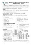
海康威视总线制报警主机操作手册

警灯
警灯
警灯
警灯
1
报警输出接口
Tx Rx G 信息输出口
复位开关 防拆开关
注意:所有接至警号、辅助电源、键
盘供电端的负载总电流不可以超过 2500mA。
供电电源:
1、推荐使用12VDC,7AH的铅酸蓄电池。 2、每3~5年更换一次符合要求的蓄电池。 3、虚线内的GPRS模块根据型号不同而有所增减,请以实物为准。
总线式网络报警主机
操作手册
杭州海康威视数字技术股份有限公司 技术热线:400-700-5998 UD.6L0106C0047A01
总线式网络报警主机.操作手册
非常感谢您购买我公司的产品,如果您有什么疑问或需要请随时联系我们。 本手册可能包含技术上不准确的地方、与产品功能及操作不相符的地方或印刷错误。我公司将根据产 品功能的更改而更新本手册的内容,并将定期改进或更新本手册中描述的产品或程序。更新的内容将会在 本手册的新版本中加入,恕不另行通知。 本手册中涉及到 GPRS 功能只适用于支持 GPRS 功能并且安装了 GPRS 模块的产品。
工作状态指示灯 网络状态指示灯 电源指示灯
GPRS模块
SIM卡槽
D+ D- +12V G
COM1
COM2
COM3
COM4
Z1 G Z2 Z3 G Z4 Z5 G Z6 Z7 G Z8 NO/NC1 NO/NC2 NO/NC3 NO/NC4
Z1 Z2
Z3 Z4
Z5 Z6
Z7 Z8
所有的EOL都是8.2K欧姆
第 2 章 安装接线.........................................................................................................................12
Connect X300 智能设备安装说明说明书

INSTALLATION INSTRUCTIONS Connect X300DescriptionConnect X300 is a physical device that is the gateway connection between a Cloud service and a controlled/monitored system. This system in a building can include fire alarm control panels, devices, sensors, detectors, etc.X61X60X63X30X31X1 P1X2 P1X70ON/OFF X80L+MEARTH SCREWX62NOT USEDNOT USEDNOT USEDNOT POWER SUPPLYFIRE PANEL INTERNET ACCESSFigure 1Connect X300 GatewayConnections and Indicators•X1P1: Connection to Desigo Fire Safety Modular/Cerberus PRO Modular via FCM2041-U2/-U3 Operator Interface.Connection to Desigo FC2025/FC2050 and Cerberus PRO FC922/FC924 via FCM2018/2019/2035-U2/-U3 Operating Units.Connection to Desigo FV2025/2050 and Cerberus PRO FV922/924 via VCA2002-A1 Card Cage.X2P1: Connection to internet networkFeatures• Two Ethernet ports for WAN and LAN• Remote firmware and configuration data update over the IP Interface • LED indication of activities and state • Operating voltage DC 24V • Max current load: 515mA DC• Plug-in screw terminal block for supply •Mounting on wall using enclosuresDepending on firmware, the following functions are supported (examples):• Multi-site management • Remote monitoringApplicationThe device integrates Desigo Fire Safety Modular, Cerberus PRO Modular, DesigoFC2025/FC2050/FV2025/FV2050, and Cerberus PRO FC922/FC924/FV922/FV924 fire panels over IP. It transmits data to the cloud over IP networks or over mobile networks (3G/4G/LTE).FunctionsThe Connect X300 provides two integration levels to connect fire alarm control panels to the cloud: System integration (between the Connect X300 and the fire panels) and cloud integration (between the ConnectX300 and the cloud). The Connect X300 supports Ethernet and 3G/4G/LTE for cloud connectivity.Mounting and WiringThe Connect X300 can be mounted inside the ENCL-01, P/N S54465-C63-A1, or PAB-ENCL Siemens enclosures using adaptor plates. Adaptor plate CGAP, P/N S54811-B101-A1, is used with the ENCL-01 enclosure while adaptor plate CGAP2, P/N S54811-B102-A1, is used for the PAB-ENCL enclosure. Refer to Figures 2 through 6.Wiring the Connect X300 Gateway inside PAB-ENCL EnclosuresTo connect the ethernet cable, see Figure 3. Use knockouts from the right side; wires are considered Power Limited. To connect the power to the Connect X300 Gateway, see Figure 2.Option: The FP2011-U1 Power Supply can be used with the cable provided to connect the power fromthe FP2011-U1 Power Supply to the Connect X300 Gateway. Use knockout close to the location of the Power Supply to enter the box. Wires are considered Non-Power Limited.Modular/Cerberus PRO Modular Enclosure)DETAIL E SCALE 2 : 512-22 AWG BlackWires are Power LimitedFor UL applications: wiring limited to20 ft in conduit located in the same room.For ULC applications: wiring inmetallic conduit located in the same roomNOTE : All high voltage and non-power limited wiring must be kept separate from power limited wiring. A ¼” separation must be maintained with high voltage and non-power limited wiring running in separate conduit openings from power wiring. Wiring within the cabinet should be routed around the perimeter of the cabinet.Figure 2Desigo Fire Safety Modular/Cerberus PRO Modular System Power Connection to Connect X300Rear View ofFCM2041-U2/-U3Operator Interface (Located in the S55842-Z121-A100Connect X300GatewayEthernet Cable 6 ft. long (User Provided)Wires are Power LimitedFor UL applications: wiring limited to20 ft. in conduit located in the same room.For ULC applications: wiring inmetallic conduit located in the same room not exceeding 18 m.NOTE : All high voltage and non-power limited wiring must be kept separate from power limited wiring. A ¼” separation must be maintained with high voltage and non-power limited wiring running in separate conduit openings from power wiring. Wiring within the cabinet should be routed around the perimeter of the cabinet.Figure 3Desigo Fire Safety Modular/Cerberus PRO Modular System Ethernet Connection to Gateway12-22 AWG BlackWires are Power LimitedFor UL applications: wiring limited toDETAIL ESCALE 2 : 5Figure 4Desigo and Cerberus PRO Power Connection to Connect X300 GatewayGateway(Can be mountedinside the enclosuresP/Ns S54465-C63-A1,S54339-A8-A1, &Figure 5Desigo and Cerberus PRO Fire Only Panel Ethernet Connection to Connect X300 GatewayGateway(Can be mounted inside the enclosures P/Ns S54465-C63-A1, S54339-A8-A1, &LOCAL CAN MODULE+24 VDCPOWER VCC LOCAL MONETFigure 6Desigo and Cerberus PRO Fire Voice Panel Ethernet Connection to Connect X300 GatewayConfiguring for the Cerberus PRO FC922/FC924/FV922/FV924 and DesigoFC2025/FC2050/FV2025/FV2050Refer to FG2004 Commissioning Guide, Document ID A6V11382550.Configuring for the Desigo Fire Safety Modular/Cerberus PRO Modular using Zeus1. Insert a Custom Enclosure.2. Under this, insert the X300 Gateway.a. To enable supervision of this gateway, check the property for Connection Supervision.i. When checked, a Not responding trouble will be reported each time the connectionbetween the Operator Interface and Connect X300 is lost.ii. By default, this property is unchecked.b. To add the gateway to the battery calculations, check the Cloud Battery Backup option.i. By default, the value is checked.Cyber security disclaimerSiemens provides a portfolio of products, solutions, systems and services that includes security functions that support the secure operation of plants, systems, machines and networks. In the field of Building Technologies, this includes building automation and control, fire safety, security management as well as physical security systems.In order to protect plants, systems, machines and networks against cyber threats, it is necessary to implement – and continuously maintain – a holistic, state-of-the-art security conc ept. Siemens’ portfolio only forms one element of such a concept.You are responsible for preventing unauthorized access to your plants, systems, machines and networks which should only be connected to an enterprise networkor the internet if and to the extent such a connection is necessary and only when appropriate security measures (e.g. firewalls and/or network segmentation) are in place. Ad ditionally, Siemens’ gui dance on appropriate security measures should be taken into account. For additional information, please contact your Siemens sales representative or visit https:///global/en/home/company/topicareas/ future-of-manufacturing/industrial-security.html.Siemen s’ portfolio undergoes continuous developme nt to make it more secure. Siemens strongly recommends that updates are applied as soon as they are available and that the latest versions are used. Use of versions that are no longer supported, and failure to apply the latest updates may increase your exposure to cyber threats. Siemens strongly recommends to comply with security advisories on the latest security threats, patches and other related measures, published, among others, under https:///cert/en/cert-security-advisories.htm.。
【宏安科】多功能铁盒电话联网报警主机说明书概要

铁盒多功能系列防盗报警控制主机安装使用说明书深圳市宏安科智能科技有限公司前言欢迎您选用铁盒多功能系列报警控制主机,本产品具有功能强大、性能优越、质量稳定、操作方便等特点;正确的使用本报警主机将为您的生命和财产提供更好的安全保障。
首先建议您在使用本系统前,认真阅读本说明书,请按说明书中要求的程序步骤进行操作。
使用本说明书,可以解答您的大部分疑问,同时,我们将提供完善的售后服务,并随时与您保持联系。
特别说明:本说明书不能作为法律文件,对于用户、操作员或安装员对手册内容的误解、误操作和系统带病运转而导致的任何损失和法律责任,我公司恕不承担。
本公司保留对本使用说明书的修改权和解释权,修改之前不再另行通知使用本产品的用户。
感谢您的支持与合作·目录前言 (2)第一章概述 (3)1.1概况 ........................................................................................................................................ .. (3)1.2使用前注意事项 (3)1.3功能简介 ........................................................................................................................................ . (3)1.4基本配置 ........................................................................................................................................ (4)1.5主要技术性能指标 (4)第二章安装接线说明 (5)2.1安装接线图 ........................................................................................................................................ .. (5)2.2电源的连接 ........................................................................................................................................ .. (8)2.3有线探测器的连接 (8)2.4 警号的连接 ........................................................................................................................................ . (8)2.5 电话线的连接 (8)2.6 监听头的连接 (9)2.7 键盘的安装 ........................................................................................................................................ . (9)2.8 仅用无线防区,不接有线防区的安装 (9)第三章系统操作 (10)3.1系统操作 ........................................................................................................................................ . (10)3.2遥控器的使用 .......................................................................................................................................103.3 键盘面板及声光指示 (10)3.4布防 ........................................................................................................................................ . (12)3.5撤防 ........................................................................................................................................ (12)3.6远程控制 ........................................................................................................................................ . (12)3.7电话接警控制 (133)3.8录音 ........................................................................................................................................ (13)3.9消警 ........................................................................................................................................ (13)3.10旁路防区查询 .....................................................................................................................................13 第四章系统设置 (144)4.1系统出厂基本设置 (14)4.2复位 ........................................................................................................................................ (14)4.3修改用户密码 .......................................................................................................................................144.4设置状态的进入与退出 (15)4.5修改安装员密码 (15)4.6无线探测器的学习 (15)4.7无线探测器的删除 (15)14.8防区类型及报警声输出设置 (155)4.9周界防区打开/关闭设置 (15)4.10 门铃功能打开/关闭设置 (155)4.11用户编号(中心编号)设置 (16)4.12布防延时时间设置 (16)4.13报警延时时间设置 (16)4.14设置报警电话号码 (16)4.16报告传输设置 ......................................................................................................................................164.17 ABC按键设置 ......................................................................................................................................164.18远程控制打开/关闭 (16)4.19远程遥控振铃声次数设置 (177)4.20远程电话接警不用输入密码操作 (177)4.21接警放录音方式的选择 (177)4.22电话线检测打开/关闭设置 (177)4.23可编程4+2代码需手动设置以适应不同的报警中心 (177)4.24主机自检报告时间间隔设置 (177)4.25警号响声时间设置 (177)4.26布撤防警号响声设置 (177)4.27定时布撤防设置 (177)4.28时间调整系数设置 (178)4.29交流电断电报警设置 (178)4.30 在设置状态下设置 (178)4.31 防区灵敏度 (178)4.32 电池低关机延时间 (178)4.33防区报警上传次数设置 (178)4.34键盘防撤开关报警功能打开、关闭设置 (178)4.35键盘断线检测设置 (19)4.36中心精度设置 .....................................................................................................................................194.37中心信号时间设置 (19)4.38拨号轮数设置 .....................................................................................................................................194.39输出模块设置 .....................................................................................................................................194.40 事件查询 ........................................................................................................................................ . (19)4.41遥控器分区管理(需订做) ...................................................................................................................................19第五章疑难问题解答 ................................... 20 产品的质量保证 ........................................ 211 安装资料 . (211)2第一章概述1.1概况铁盒多功能报警控制主机采用先进的微处理技术作为控制核心,集成度高,可靠性强,具有多种灵活接口,能同时储存6组报警电话号码和3组中心号码(如管理中心、固定电话或移动手机号码),通过电话线通讯网络传递报警信息。
(参考)消防自动报警使用说明书

(参考)消防⾃动报警使⽤说明书消防⾃动报警/联动系统操作说明第⼀部分:值班⼈员操作指南⼀、系统简介:探测部分:包括各种探测器。
整个系统管理部分:包括各型控制器。
联动控制:各种模块。
辅助部分:包括电源盘、⽕灾显⽰盘、CRT等。
探测器的作⽤:监视保护区,把⽕警信息传给控制器,包括感烟、感温、感光等多种类型。
控制器的作⽤:接收显⽰⽕警信息,⼿动⾃动控制联动设备。
模块的作⽤:接收控制器的控制灭⽕设备及辅助设备的指令,通过模块内的继电器使相应设备启动,同时可接收设备的动作信息。
电源盘的作⽤:输出直流24V电源,给模块、⽕灾显⽰盘等设备供电。
⼆、开机及注意事项:1、开机顺序:(关机顺序与开机顺序相反)1)原则:先开备电开关,后开⼯作开关;先开电源盘(箱)开关,后开控制器开关;先开从机(包括⽕灾显⽰盘)开关,后开主机开关。
(柜式控制器开机前先打开后⾯的空⽓开关)控制器部分开机后,再打开消防电话主机、消防⼴播系统的卡座、功放、CRT等。
9000主机先开2机箱,再开1号机箱.关机则反之.2)说明:⼯作开关、备电开关位置:见具体设备及相应使⽤说明书。
打开备电开关作⽤:平时给备电充电,交流掉电时备电⾃动投⼊使系统保持正常⼯作。
2、开机时注意事项:1)主电是否正常(交流电压显⽰不在187V-242v之间、主电故障指⽰灯亮或设备报主电故障);2)备电是否正常(备电故障指⽰灯亮或设备报备电故障);3)电源盘(箱)电压输出是否正常(正常在24-2627v之间);4)各个指⽰灯、数码管、液晶屏是否正常点亮,声⾳是否正常;5)是否显⽰总线故障,如显⽰表⽰总线短路,应⽴刻关机,待排除线路故障后再开机。
3、控制器开机时的正常显⽰过程:依次点亮指⽰灯、数码管,液晶屏,显⽰各种信息,并顺序发出各种声⾳(⽕警、故障、动作等声⾳),然后检测总线和通讯线上所连接的设备。
4、开机后注意事项:1)查看时间、⽇期显⽰是否准确,如不准确,调整时间、⽇期;2)报警控制器报警是否正常;3)联动设备在⼿动盘上⼿动启动设备是否正常;4)有⽆异常现象出现;如有外界强⼲扰造成机器死机(⽆时间显⽰,键盘不能操作),可关机后重新开机看能否恢复正常。
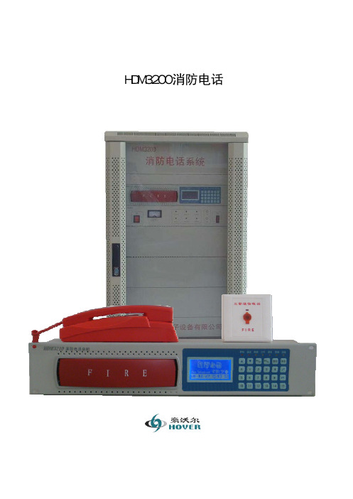
HDM3200消防电话使用说明书

HDM3200消防电话使用说明书北京豪沃尔电子设备有限公司 注意事项前言注意:用户在安装、使用产品前,请阅读本说明书以及机器上标明的所有警告及说明事项。
如果您遵从以下有关安装、使用以及保养步骤,系统会处于良好工作状态。
本机是完全集成化的装置,并无用户可以修理的部件。
一概述感谢您选用我们的HDM3200消防电话系统。
HDM3200消防电话系统是为适应用户的不同需要,并严格按照国家标准GB16806-2006设计开发的一款采用二总线技术的新型消防应急通讯产品。
是广泛应用于建筑物及公共场所内消防控制系统中的重要通信设备。
HDM3200消防电话系统包括HDM3210消防电话主机,HBM1001消防电源以及备用电池组成。
HDM3210消防电话总机可接入HD312台壁式消防电话分机、HD322消防电话插孔以及和它配套的HD220插孔式消防电话分机,构成完善的消防应急通信系统,适用于建筑内发生火灾或紧急情况时与中心控制室通讯、调度。
当应用现场出现紧急情况时,现场人员通过本系统快速与中心控制室取得联系,或中心指挥系统由其它系统得到紧急信息,通过火警广播通信系统调度指挥现场,通过广播快速指挥或疏散人员。
为使用户尽快熟悉和正确使用该设备,针对本系统编制了这本使用操作说明书。
1. HDM3200消防电话采用四门式标准机柜,侧门可拆卸,便于安装调试。
前面为超大钢化玻璃门,方便系统监控,前后门均配有门锁,防止误操作。
2. HDM3210消防电话主机使用标准直流24伏供电,前面板镶嵌电话座整体注塑件结构,轻触式按键,数字键盘输入,人性化操作,大型液晶显示屏,蓝色背光显示,实时时钟显示,美观大方、线条流畅。
给使用、安装和维护带来了极大便利,具有结构紧凑、安装方便、通用性强、使用灵活、应用范围广,可靠性高等特点。
3. HDM3210消防电话主机与分机HD312、HD322、HD220组成电话系统,可应用于建筑物内紧急情况下的语音通信。
火灾报警设备安装说明书

火灾报警设备安装说明书一、前言感谢您选择我们的火灾报警设备。
为了确保设备的正常运行和安全使用,本文将提供详细的安装说明,以帮助您正确地安装和使用火灾报警设备。
二、设备准备在安装火灾报警设备之前,请确保已准备好以下设备和材料:1. 火灾报警控制主机2. 火灾报警探测器(烟雾、火焰、温度等)3. 报警按钮4. 区域划分图5. 控制主机安装支架6. 探测器安装底座7. 探测器安装支架8. 电源线、通信线等连接线缆9. 安装工具(螺丝刀、电钻、梯子等)10. 安全设备(手套、护目镜等)三、安装步骤1. 确定安装位置根据区域划分图和实际情况,选择合适的位置安装火灾报警设备。
安装位置应远离易燃物品,避免受潮和高温环境。
同时,设备应安装在易于触及和操作的位置,以便紧急情况下的报警操作。
2. 安装控制主机将控制主机安装支架固定在合适的位置上,然后将控制主机放置在支架上,并确保与电源线和通信线等连接线缆连接良好。
3. 安装报警探测器根据区域划分图,确定各个区域的火灾报警探测器的安装位置。
将探测器安装底座安装在合适的位置上,然后将探测器安装支架安装在底座上。
最后,将探测器固定在安装支架上,并确保与控制主机连接稳固。
4. 安装报警按钮根据实际情况,确定报警按钮的安装位置。
将报警按钮安装在容易寻找和按压的位置上,并确保与控制主机连接正常。
5. 连接电源线和通信线根据接线图,将电源线和通信线等连接线缆连接到控制主机和各个报警设备上。
确保连接正确且牢固。
6. 电气连接检查完成所有安装步骤后,检查控制主机和报警设备的电气连接是否正确,确保无短路、断路等情况发生。
7. 开启系统测试在安装完成后,进行系统测试。
将系统切换为测试模式,依次触发各个探测器和报警按钮,确保设备报警正常,并及时清除报警状态。
8. 完成安装当系统测试通过后,确认一切正常后,即可完成安装。
四、注意事项1. 在安装和操作过程中,务必佩戴好安全设备,如手套、护目镜等,确保人身安全。
消防16路多线电话说明书

消防16路多线电话说明书
一、使用说明
1、该分机主要配合消防电话总机使用,全部电路及送受器均装入电话机身内,不用拨号,该机配有火警电话标志。
2、电话分机引线方式:
(1)U型端子,可直接与火警电话主机连接,分机可放于底座内,只要摘机即可呼叫主机。
(2)音频Φ6.5 插头,通过电话插孔与火警通讯盘连接。
消防人员可随身携带只要插入现场的消防电话分机插孔即可呼叫主机。
(3)水晶插头,通过电话插孔与火警通讯盘连接。
消防人员可随身携带只要插入现场的消防电话分机插孔即可呼叫主机。
二、主要技术指标
频率范围:300~3400Hz(±3dB)
串音电平:不大于-60 dB(600 欧负载)
传输衰耗:不大于 5 dB。
消防电话说明书

1.概述11.1产品特点11.2主要用途及使用X围11.4使用环境条件及工作条件11.5对环境及能源的影响12.结构特征与工作原理13.技术特性23.1主机23.2分机23.3模块34.尺寸、重量35.安装、调试36.使用及操作36.1主机36.2分机76.3模块77.故障分析与排除78.安全保护装置及事故处理89.保养与维修810.包装、贮存811.开箱及检查812.产品三包服务办法:81.概述消防系统是指当应用现场出现紧急情况时(如:火警、匪警及其它突发性灾害事件),它能提供方便的通讯手段,分布在应用现场的分机可以呼叫主机,及时与控制中心取得联系;主机也可以呼叫位于现场的分机了解现场情况。
系统可以详细记录呼叫、接通时间及通话内容。
1.1产品特点●系统配备的消防YJG3295主机,它可以与分机进行可靠的通讯,并且详细记录呼叫、通话时间及内容。
可在紧急情况直接呼叫119,可接通来自外线的呼叫。
可对在线的分机进行一次登记并保持运行过程中的实时检测,对登记存在的分机出现通讯故障可快速作出报警,便于日常的维护。
●系统配备YJGF3295A分机可以呼叫主机,接听来自主机的呼叫;配备YJGF3040B话机手柄和YJGF3295C模块插孔可以呼叫主机。
●本系统主机采用两总线制,可挂接95个独立地址编码的分机及模块,通讯可靠性高,便于维护。
1.2主要用途及使用X围●用于现场出现紧急情况时(如:火警、匪警及其它突发性灾害事件),它能提供方便的通讯手段,分布在应用现场的分机可以呼叫主机,及时与控制中心取得联系,主机可以呼叫位于现场的分机了解现场情况,系统可以详细记录呼叫、接通时间及通话内容。
●适用于总线通讯方式。
1.3型号的组成及其代表意义图1YJ G □ 3 2-□ □A-分机C-模块95-分机路数2-2总线3-消防电话类F-分设备国标首字母原杰公司首字母1.4使用环境条件及工作条件●环境温度:0~+40℃;相对湿度:≤85%;气压:860~1060毫巴●工作电压:DC24V±20%1.5对环境及能源的影响●本系统设备采用的都是方便易得的常规器件,生产过程对环境不存在有毒有害污染;●本系统线路采用两总线,现场布线简捷、避免资源浪费。
HD 火灾保护有限公司产品说明书

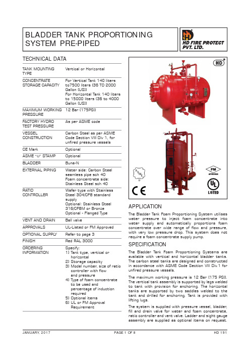
BLADDER TANK PROPORTIONING SYSTEM PRE-PIPEDTANK MOUNTING Vertical or HorizontalTYPECONCENTRATE For Vertical Tank 140 liters STORAGE CAPACITY to7500 liters (36 TO 2000 Gallon (US)) For Horizontal Tank 140 liters to 15000 liters (36 to 4000 Gallon (US))MAXIMUM WORKING 12 Bar (175PSI) PRESSURE FACTORY HYDRO As per ASME codeTEST PRESSURE VESSELCarbon Steel as per ASME CONSTRUCTION Code Section VIII Div 1, forunfired pressure vessels CE MarkOptional ASME “U” STAMP OptionalBLADDER Buna-NEXTERNAL PIPING Water side: Carbon Steel seamless pipe sch 40Foam concentrate side:Stainless Steel sch 40RATIO Wafer type with Stainless CONTROLLER Steel 304/CF8 standardsupply Optional: Stainless Steel 316/CF8M or Bronze Optional - Flanged Type VENT AND DRAIN Ball valveAPPROVALS UL-Listed or FM Approved OPTIONAL SUPPL Y Refer to page 3FINISHRed RAL 3000ORDERING Specify:INFORMATION 1) Tank type, vertical orhorizontal2) Storage capacity3) Model number , size of ratiocontroller with flowand pressure 4) Type of foam concentrate to be used and percentage of induction required 5) Optional items 6) UL or FM ApprovalRequirementTECHNICAL DATAAPPLICATIONThe Bladder Tank Foam Proportioning System utiliseswater pressure to inject foam concentrate into water supply and automatically proportions foam concentrate over wide range of flow and pressure, with very low pressure drop. This system does not require a foam concentrate supply pump.SPECIFICATIONThe Bladder Tank Foam Proportioning Systems are available with vertical and horizontal bladder tanks. The carbon steel tanks are designed and constructed in accordance with ASME Code Section Vlll Div.1 for unfired pressure vessels. The maximum working pressure is 12 Bar (175 PSI). The vertical tank assembly is supported by legs welded to tank with provision for anchoring. The horizontal tanks are supported by two saddles welded to the tank and drilled for anchoring. Tank is provided with lifting lugs.The system is supplied with pressure vessel, bladder , fill and drain valve for water and foam concentrate, ratio controller and vent valve. Ladder and sight gauge assembly are supplied as optional items on request.All valves are labeled showing normal working position and function.All tanks are oversized for allowing thermal expansion of the foam concentrate, if any.PRINCIPLE OF OPERATIONThe instructions for filling are provided with the equipment. Once the main water flow is established and water inlet and foam outlet valves are opened, the water enters the area between vessel wall and bladder , applying pressure to the bladder . The foam concentrate is forced out of the bladder through the foam concentrate outlet pipe and into the ratio controller through metering orifice. The concentrate pressure and water inlet pressure at ratio controller will be same, as the main water supply pressure is utilised to expel the foam from the bladder . The water flowing through the ratio controller jet creates a low pressure area common both to down stream water and foam concentrate. This injects the concentrate in to the ratio controller through an accurate sized orifice proportioned to water venturi. This ensures correct proportioning over a wide range of flow condition.The bladder tank proportioning system operates on same principle as that of a balance pressure proportioning system. In bladder system, the bladder is used as diaphragm to separate the water and foam concentrate within the tank. The foam concentrate is injected into the ratio controller utilising water pressure.The system is also supplied with foam concentrate control valve as an optional item. The valve allows concentrate flow only when minimum of 2.1 kg/sq.cm. water pressure is established in the system. For pressure drop and flow characteristics refer catalogue of ratio controller .HD FIRE Bladder tanks and proportioners are UL Listed and FM Approved with various HD foam concentrates, refer indivisual listing and approval data.“U’ stamp (American Society & Mechanical EngineersASME) code stamp. This ASME certification is optional.Bladder tanks 900 Liters and larger are CE marked on conformance with the European Pressure EquipmentDirrctries. CE marking is optional.SELECTION OF HORIZONTAL /VERTICAL BLADDER TANKSAdvantages of Horizontal bladder tanks (i) Better stability than vertical tank in earthquake prone area (ii) Easier to refill than vertical tanks (iii) Easy to transport, store and install (iv) Large CapacityAdvantages of Vertical bladder tanks(i) Require less floor space than horizontal tanksINSTALLATION, INSPECTION AND MAINTENANCEAn installation, inspection and maintenance manual is packed with each unit. The manual provides detail schematic, initial procedure, inspection and maintenance procedures. The instruction manual must be read carefully and followed during installation and commissioning of the system.After few initial successful tests an authorised person must be trained to perform inspection and testing of the system. It is recommended to carry out physical inspection of the system regularly, the inspection should verify that no damages have taken place to any component and all the valves are in their proper position as per the system requirement. The system should be fully tested at least once in a year and in accordance with applicable NFPA code or in accordance to the guidelines of the organisation having local jurisdiction.Do not turn off the system or any valve to repair or test the system, without placing a roving Fire Patrol in the area covered by the system. The patrol should continue until the system is put back in service. Also inform the local security personnel and the control room so that a false alarm is not signalled.CAUTION1) Do not weld on the tank as it may damage the bladder fitted inside the tank.2) Release pressure before an inspection and maintenance of the system.3) Sight gauge is not pressure tight, so before taking concentrate level reading, tank pressure must be released.4) The bladder tank is to be installed under a shade to avoid direct sunlight on the equipment.5) While designing a foam system, step shall be takento allow for removal of the internal centre tube(s). The centre tubes are full length and/or height ofthe bladder tank.6) ASME Code may require over pressure protection before pressurising the system. HD FIRE does not supply an over pressure relief valve with the tanks. It shall be the owner’s responsibility to provide over pressure protection for thetank in accordance to ASME Code.7) Foam concentrate filling procedure mustbe followed. Incorrect filling procedure may damage the bladder . HD product have limited warranty and incorrect fill procedure will void the warranty.NOTE1) The foam concentrate is to be filled in the bladdervery carefully to avoid rupture of bladder.The filling guidelines provided with the equipmentmust be strictly adhered.2) Air supply with regulator (0 to 1.0 kg/sqcm)required during filling procedure, to be arrangedby installer / user.3) Water supply at 0-1.5 kg/sqcm required fortank filling during commissioning, to be arrangedby installer / user.4) Concentrate fill pump need to be arranged byinstaller / user.5) A minimum length of 5 (five) times the pipediameter of unobstructed straight pipelineshould be provided at the inlet and outlet of theratio controller, where pipe diameter is thenominal size of the ratio controller.6) For FM Approval of Bladder tank is applicableonly FM Approved Bladder tank, Ratio Controller, Foam Concentrate and Dischage Deviceareinstalled.7) Concentrate control valve is requirement forFM Approval and is not permited by UL.Hence Tanks will be either UL Listed or FMApproved.8) Multiple Ratio Proportioners cannot be usedif it is UL Listed Bladder tank.9) FM Approved Bladder tank permits maximumtwo Ratio Controllers.10) Each tank is designed & tested for specifictype of foam concentrate, hence specify in order the concentrate type to be used.OPTIONAL SUPPLY• Sight gauge with shut off and drain valve (glass or polycarbonate material)• Ladder• Pressure Guages• Concentrate control valve• Filling kit with Foam concentrate fitting pump• Stainless steel pipe for water supply side• Stainless steel pipe & valve standard supply SS304/CF8. Optional is SS316/CF8M or SS316L • Painting as per specific requirement• Seismic designed tanks • Custom design for higher rating, material and dimension• Coal Tar epoxy internal coating, standard supply or any other paint as per customer requirement• Ratio controller material Bronze, Stainless steel CF8, CF8M• Relief valve is not included in standard supply it is optional as per specific customer requirement• Corrotion alloance.RELIEF VALVE (OPTIONAL SUPPLY)(i) Thermal Relief valve(ii) Full flow, as per ASME(iii) Full flow, ASME “U” StampedLISTING & APPROVAL1) Bladder tank proportioning system is UL Listed orFM Approved as pre-piped system.2) Listing and Approval is valid only when used inthe manner as outlined in the applicable Listing andApproval.3) Concentrate supply valve is standard supplywith FM Approved Bladder tank.4) CE marking is optional.5) ASME “U“ stamp is optional.SHIPPING DETAILSi) All the tank openings will be plugged for shipping. ii) All pre-piped pipes, valves, pressure gauges, sight gauge etc will be packed separately for shipping. iii) Tank will be mounted on pallet with crate all over as standard packing system of HD FIRE. For anycustom packing requirement contact HD Sales.* Concentrate control valve is standard supply with FM Approved Bladder tank and not supplied with UL Listed as UL do not allow Concentrate control valve.* Concentrate control valve is standard supply with FM Approved Bladder tank and not supplied with UL Listed as UL do not allow Concentrate control valve.* V1 is standard supply with FM Approval and not supplied with UL Listed as UL do not allow Concentrate control valve.* V1 is standard supply with FM Approval and not supplied with UL Listed as UL do not allow Concentrate control valve.LIMITED WARRANTYHD FIRE PROTECT PVT. L TD. hereby referred to as HD FIRE warrants to the original purchaser of the fire protection products manufactured by HD FIRE and to any other person to whom such equipment is transferred, that such products will be free from defect in material and workmanship under normal use and care, for two (2) years from the date of shipment by HD FIRE. Products or Components supplied or used by HD FIRE, but manufactured by others, are warranted only to the extent of the manufacturer’s warranty. No warranty is given for product or components which have been subject to misuse, improper installation, corrosion, unauthorized repair , alteration or un-maintained. HD FIRE shall not be responsible for system design errors or improper installation or inaccurate or incomplete information supplied by buyer or buyer’s representatives.HD FIRE will repair or replace defective material free of charge, which is returned to our factory, transportation charge prepaid, provided after our inspection the material is found to have been defective at the time of initial shipment from our works. HD FIRE shall not be liable for any incidental or consequential loss, damage or expense arising directly or indirectly from the use of the product including damages for injury to person, damages to property and penalties resulting from any products and components manufactured by HD FIRE. HD FIRE shall not be liable for any damages or labour charges or expense in making repair or adjustment to the product. HD FIRE shall not be liable for any damages or charges sustained in the adaptation or use of its engineering data & services. In no event shall HD Fire’s product liability exceed an amount equal to the sale price.The foregoing warranty is exclusive and in lieu of all other warranties and representation whether expressed, implied, oral or written, including but not limited to, any implied warranties or merchantability or fitness for a particular purpose. All such other warranties and representations are hereby cancelled.NOTICE :The equipment presented in this bulletin is to be installed in accordance with the latest publication standards of NFPA or other similar organisations and also with the provision of government codes or ordinances wherever applicable.The information provided by us is to the best of our knowledge and belief, and consist of general guidelines only. Site handling and installation control is not in our scope. Hence we give no guarantee for result and take no liability for damages, loss or penalties whatsoever , resulting from our suggestion, information, recommendation or damages due to our product.Product development is a continuous programme of HD FIRE PROTECT PVT. L TD. and hence the right to modify any specification without prior notice is reserved with the company.D-6/2, ROAD NO. 34, WAGLE INDUSTRIAL ESTATE, THANE 400 604, INDIA.• TEL: + (91) 22 2158 2600 • FAX: +(91) 22 2158 2602•EMAIL:***************• WEB: HD FIRE PROTECT PVT . LTD.Protecting What Matters Most to You。
通信设备安装作业安全操作手册

通信设备安装作业安全操作手册通信设备的安装是一项复杂且具有一定危险性的工作。
为了保障施工人员的生命安全,确保安装工作的顺利进行,特制定本安全操作手册。
一、施工前准备1、了解工程情况施工人员在进行通信设备安装前,必须对工程的整体情况有清晰的了解,包括设备的类型、数量、安装位置、施工环境等。
2、制定施工计划根据工程情况,制定详细的施工计划,包括施工流程、施工进度、人员安排等。
施工计划应合理安排施工顺序,避免交叉作业,减少安全隐患。
3、人员培训所有参与通信设备安装的施工人员必须经过专业的安全培训,熟悉通信设备安装的操作规程和安全注意事项。
培训内容应包括电气安全知识、高处作业安全知识、机械操作安全知识等。
4、工具和设备检查施工前,应对所使用的工具和设备进行全面检查,确保其性能良好、安全可靠。
对于存在故障或损坏的工具和设备,应及时维修或更换。
5、个人防护用品准备施工人员应配备符合国家标准的个人防护用品,如安全帽、安全带、安全鞋、手套等。
个人防护用品应定期检查和维护,确保其防护性能有效。
二、现场安全管理1、施工现场布置施工现场应合理布置,设置明显的安全警示标志,划分施工区域和非施工区域,保持施工现场的通道畅通。
2、安全交底施工负责人应在施工前向施工人员进行安全交底,将施工中的安全风险、安全措施和应急处理方法告知施工人员。
3、现场监护在进行高处作业、动火作业等危险作业时,必须安排专人进行现场监护,确保施工安全。
4、安全检查定期对施工现场进行安全检查,及时发现和消除安全隐患。
对于发现的安全问题,应立即采取措施进行整改。
三、电气安全1、断电操作在进行通信设备安装前,必须先切断电源,并在电源开关处悬挂“禁止合闸,有人工作”的警示牌。
严禁带电作业。
2、电气设备接地通信设备的电气设备必须可靠接地,以防止触电事故的发生。
接地电阻应符合国家标准的要求。
3、电线电缆敷设电线电缆的敷设应符合规范要求,避免电线电缆受到挤压、磨损、拉扯等。
城市消防指挥系统安装手册(doc 67页)

城市消防指挥系统安装手册(doc 67页)城市消防通信指挥系统安装手册深圳市亚奥数码技术有限公司目录第一部分WINDOWS NT4.0操作系统安装说明 (6)第一章概述 (6)第二章系统安装过程 (7)第三章补丁安装过程 (11)第四章注意事项 (11)第二部分ORACLE数据库安装说明 (12)第一章概述 (12)第二章数据库服务器安装过程 (13)第三章数据库客户端安装 (20)第四章Oracle 的卸载 (24)第三部分应用程序安装说明 (26)第一章概述 (26)第二章火警受理台安装 (27)第三章数据维护台安装 (33)第四章电子地图安装 (34)第五章数字录音安装 (35)第六章火警终端台安装 (36)第四部分MAPINFO PROFESSIONAL 5.0安装说明 (37)第一章简述 (38)第二章安装 (39)第三章软件的卸载 (52)第五部分MAPX和数据库驱动安装说明 (53)第一章概述 (53)第二章安装过程 (54)第三章数据库驱动安装 (57)第六部分数字录音系统的安装说明 (58)第七部分119拨号方式调度实现 (62)第八部分一机双屏卡安装使用说明 (82)第一章概述 (82)第二章安装过程 (83)第三章使用方法 (89)第四章注意事项 (91)第九部分中队联动设备安装说明 (93)第一部分 Windows NT4.0操作系统安装说明第一章概述Windows NT4.0是一个性能优异的32位网络操作系统,他与Windows95具有类似的界面,且使用方法完全一致。
Windows NT4.0支持目前流行的各种网络协议,如:TCP/IP,DLC,NWLINK,IPX/SPX兼用协议,NETBEUI等,使得多种客户机(如MS—DOS,Windows3。
X,Windows95,Windows FORWORKGROUPS,MACINTOSH等)只要稍加设置即可进入Windows NT网络。
RD4000中文手册

设备安装使用说明.doc

设备安装使用说明1。
产品介绍1.1中央报警控制主机中央报警控制主机中央报警控制主机作为地波微震动探测报警系统的核心管理和控制平台,可联接1—8个监控子区域设备(地波微震动探测报警器)。
1。
2地波微震动探测报警器地波微震动探测报警器,作为地波微震动探测报警系统的信号采集、信号预分析、信号传输平台。
可连接8个地波微震动传感器,将前端被监控现场的地波微震动传感器回传的精密光学微震感知信号,进行无损还原,科算,信号预分析,音频从信号中提取,信号按通道向中央报警控制主机回传.1。
2.1前面板前面板示意图序号名称数量说明备注1电源指示灯1个电源开启时点亮.2 网口工作指示灯4个对应后面板四个以太网接口,网络连接时闪烁。
3探点工作指示灯8个双色指示灯。
工作状态蓝色,报警状态。
4 FC光纤法兰盘8对每对可连接地波微震动传感器的两根FC连接器。
前面板接口说明表1.2.2后面板前面板示意图序号名称数量说明备注1 电源及电源开关1套AC 220V2 设备序号选择器1组3 音频输出接口1个实时复核时音频输出4 开关量输出8组5以太网接口4个10/100M自适应网口前面板接口说明表(1)设备序号选择器在一个系统中对多台报警器进行寻址时需要使用设备序号,设备序号选择器用于定义报警器的设备序号,如下:设备序号H L100 0 02 0 00 13 0 0 1 04 0 0 1 15 0 1 0 06 010 17 0 1 108 0 1 1 19 1 0 0 010 1 0 0 111 1 0 1 012 1 0 1 113 1 10014 1 1 0 115 1 1 1 016 1 1 1 1设备序号选择器对应表(2)开关量输出开关量引脚定义报警状态— NC - NO报警中连通断开不报警时断开连通开关量引脚连接表(3)以太网接口以太网接口用于将报警器与控制主机联网,详见组网方式。
地波微震动传感器(接口图解待补充)2.组网结构2.1通信网络通信网络采用标准RJ45网口、5类网线、以太网交换机,通过报警控制主机和探测报警器的以太网接口,组成局域网.根据不同的报警器数量,有以下几种常见的组网方式:2。
- 1、下载文档前请自行甄别文档内容的完整性,平台不提供额外的编辑、内容补充、找答案等附加服务。
- 2、"仅部分预览"的文档,不可在线预览部分如存在完整性等问题,可反馈申请退款(可完整预览的文档不适用该条件!)。
- 3、如文档侵犯您的权益,请联系客服反馈,我们会尽快为您处理(人工客服工作时间:9:00-18:30)。
HDX3000消防电话
安装使用说明书
北京豪沃尔电子设备有限公司
注意:用户在安装、使用产品前,请阅读本说明书以及机器上标明的所有警告及说明事项
1. 概述
感谢您选用我们的HDX3000消防电话。
它是由本公司生产的HDM3210消防电话总机、消防电源、电源状态显示操作面板等组成。
HDM3210消防电话总机采用二总线技术,满足国家标准GB16806-2006。
本产品适用于建筑内发生火灾或紧急情况时与中心控制室通讯、调度。
当使用现场出现紧急情况时,现场人员通过本消防电话快速与中心控制室进行联络;中心指挥系统也可由其它系统获取紧急信息,通过本消防电话调度指挥现场,快速指挥或疏散人员。
本产品采用壁挂箱式结构,箱门装有玻璃,方便系统监控,配有门锁,防止误操作。
2. 技术特性
备电电池标准配置12V/4Ah 2节
备电充电电流≤1.5A
外形520(长)×320(高)×125(厚)
重量7.6kg(未装电池)
其他技术特性请参考《HDM3210消防电话总机、HD312台壁式消防电话分机、HD322台壁式消防电话分机插孔座使用说明书》。
3. 接线安装
3.1 电话总线的详细连接方法参考《HDM3210消防电话总机、HD312台壁式消防电话分机、
HD322台壁式消防电话分机插孔座使用说明书》。
图1
3.2将具有良好接地的AC220V电源接入本机电源输入端(注意电源接线标志,不要接错),将
铅酸免维护电池(BT-12M4.0AC)接到本机电源的电池接口(注意正负极)。
a)为确保通话质量,请良好接地。
b) 为确保整机性能,电话总线电缆请尽量采用优质的双绞线电缆,当环境电磁干扰恶劣
时,可考虑使用双芯屏蔽线。
3.3 使用4个M6的膨胀钉将消防电话挂于无水、通风、无阳光直照的墙壁上,安装尺寸见图2
图2
4. 操作说明
4.1电源部分操作说明
4.1.1指示灯和键操作说明
图3 电源状态显示操作面板
上图中:
1.主电工作指示灯 2. 主电欠压指示灯 3.备电欠压指示灯 4. 自检按键
5. 消音按键 6. 备电故障指示灯 7. 充电状态指示灯 8. 备电工作指示灯 指示灯和按键操作说明:
1.主电工作指示灯:用于电源工作指示
2. 主电欠压指示灯:供电电压低于主电欠压值时显示
3. 备电欠压指示灯:电池供电电压低于备电欠压值时显示
4. 自检按键: 按下后电源显示板的所有指示灯显示,蜂鸣器鸣响
5. 消音按键: 蜂鸣器在电源报警状态下鸣响时,按下后报警音停止
6. 备电故障指示灯:备电出现故障时显示
7. 充电状态指示灯:电池充电时显示
8. 备电工作指示灯:电池供电时显示
4.1.2操作说明
4.1.2.1接通主电(AC220V)电源开关,主电工作灯亮,备电故障灯亮。
4.1.2.2接通备电电源开关,备电故障灯灭,充电状态灯亮,电源开始对电池充电。
4.1.2.3当主电电压低于主电欠压值时,主电欠压灯亮,当主电电压低于切换电压值时,电源自
动切换到备电工作状态。
4.1.2.4备电单独工作蓄电池电压低于备电欠压电压值时,备电欠压灯亮,备电工作蓄电池电压
低于备电关断电压值时,切断电源输出,对电池实行保护,避免电池过放电而损坏。
4.1.2.5与本说明书介绍的电源产品相配套的备电电池不由本公司生产。
4.1.2.6电源采用脉宽调制技术,内部采用高频变压器和电感作为变换和储能部件,在输出端带
动较大负载时,电源内部有轻微音频声响属正常现象,一般在极其安静环境中离电源1
米内可听到。
4.1.2.7本电源的备电电池组,连接前应测试电池组端电压,要求电池端电压应大于DC16V,否
则电源认为备电欠压故障,不准许单独接入供电系统,对于亏电电池组,首先将其正确
接入消防电源充电道内,再将AC220V正确接入并使电源对电池充电48小时以上,才可
实现正常的备电功能。
正确更换保险管,需更换保险管时请严格按照电源上保险注明容
量更换。
4.1.2.8按下消音键,消除蜂鸣器报警。
按下自检键,检查各个指示灯和蜂鸣器是否正常,若指
示灯全亮、蜂鸣器鸣响,说明电源显示控制正常。
注:上述主电欠压值约AC187V,备电欠压值约DC21.3V,切换电压值约AC165V,备电关断电压值约DC19.3V。
操作与指标的更详细内容参考本公司HBB0500相关说明。
B: 电话主机操作说明
图4 HDM3210消防电话主机前面板
说明:
1.通话手柄 语音信息输入输出 10. 呼叫/通话键 呼叫或与分机通话
2.液晶显示屏 操作、功能显示 11. 消音键 暂时关闭声报警
3. 上方向键 菜单或数据输入 12. 消音灯 报警静音指示
4.下方向键 菜单或数据输入 13. 录满灯 记录或录音满90%指示
5.确认/放音键 输入确认或重放录音 14. 录音灯 通话时自动录音指示
6.退出/停止键 退出操作或停止放音 15. 工作灯 总机电源显示
7. 复位键 系统复位清除故障点 16. 故障灯 各类故障指示
8. 数字键 数据或分机地址输入 17. 通话灯 接通功能确认
9. 挂机键 主机挂断分机 18. 呼叫灯 分机呼叫指示
有关HDM3210总线电话主机的详细使用方法请参考本公司《HDM3210消防电话总机、HD312台壁式消防电话分机、HD322台壁式消防电话分机插孔座使用说明书》。
五故障分析与排除
在安装和使用本系统之前,请详细阅读本说明书。
如果您使用本系统时遇到下列问题,请采取相应对策进行解决,如果在采取下列对策仍无法排除故障时,请与本公司或经本公司授权的技术服务中心联系,请不要自行维修,以免扩大故障范围。
故障现象原因分析排除方法备注
检查供电电源是否有DC24V电压输入接通
电话总机
检查主机DC24V电源接线极性是否连接正确正确连接
工作灯不显示检查电源输入保险管是否导通更换保险管
分机线路故障
分机与总线未连通
将总线连于“外挂”端子上
测量总线电压是否大于DC18V
正确连接
加粗总线
分机故障持续
增加时,检查总
线是否开路
分机外挂故障分机“外挂”端子未接入51k电阻
外挂插孔连接断路
正确连接
报告总线故障总线负载超过500mA或总线有短路,测量总
线电压是否大于DC18V
正确连接
系统断电后时钟日期为00年HDM3210机箱内电池无电更换电池
电池规格为
G12/3V
六 装箱清单:
名称 型号 数量 消防电话 HDX3000 1 说明书 1 。
