应力腐蚀试验的试样
应力腐蚀及环境氢脆测试方法

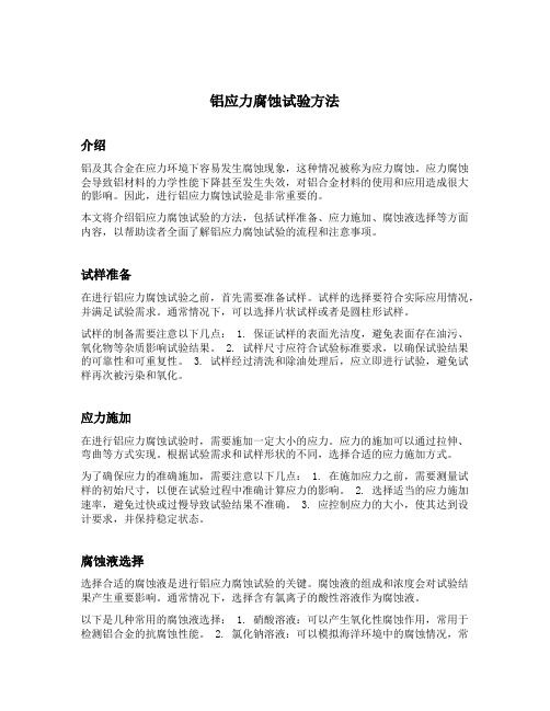
K1-tF曲线
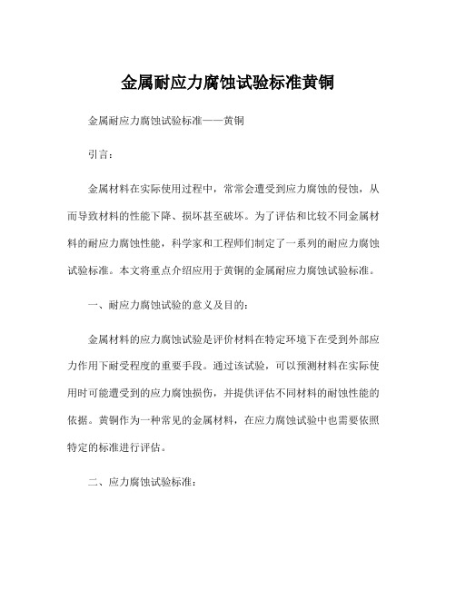
五、慢应变率法试验
慢应变率法,又称恒 应变率法,它是将拉伸试 样放在特定的介质中,然 后在慢应变率试验机上, 用一定的、缓慢的应变速 度进行拉伸试验,直到拉 断。
SERT型慢应变应力腐蚀试验机
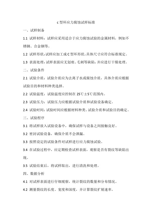
六、应力腐蚀案例
不锈钢管与管板胀接部位的横向裂纹
管与管板连接方式很多,在应 力腐蚀工程事故分析中,多遇到胀 -焊连接,仅胀未焊连接还仅焊未 胀连接三种。部分胀-焊连接方式 见图。 大量事故分析表明,不论是胀 -焊还是仅胀未焊连接,不锈钢管 束应力腐蚀裂纹多位于胀与未胀过 渡区。 这与滚胀连接时,局部变形, 受有较大的纵向残余拉应力有关。 实测表明,此处纵向应力一般高达 相当于屈服强度的数值。
典型的da/dt-K曲线(K为应力强度因子)
8、破裂电位范围和临界破裂电位
大量的例子表明,对于某一特定体系应力腐蚀 破裂只发生于一定的电位以上,低于这个电位则不 会发生,这个电位值称为应力腐蚀破裂临界电位。
在沸腾的42%MgCl2 溶液中,18-8Ti 不锈钢的电位-断裂 时间关系
二、试样及测试方法的类型
b、三点弯曲试样
恒应变三点弯曲 试样及试验装置
恒载荷三点弯曲试验
1-棒;2-试样; 3-荷重
C、四点弯曲试样
恒应变四点弯曲试样及试样架
恒应变四点弯曲试样及试样架
1-棒;2-试样;3-荷重
d、双弯梁
3、U形弯曲试样
U形试样 弯曲过程
常用的U形试样
1-焊接或缚紧;2-焊接;3-夹紧前;4-受力试样
水中Cl-浓度对 0Cr18Ni10钢SCC 敏感性的影响
5、应力腐蚀破裂敏感系数
在特定条件下,把应力腐蚀破裂时间的倒 数,称为破裂敏感系数。当破裂敏感系数越大时, 材料的应力腐蚀敏感性也越大。
氯化镁应力腐蚀试验标准
氯化镁应力腐蚀试验标准氯化镁应力腐蚀试验标准1.目的本标准旨在规定氯化镁应力腐蚀试验的方法和程序,以评估金属材料在氯化镁溶液环境下的应力腐蚀敏感性。
通过本试验,可以了解金属材料在特定条件下的应力腐蚀裂纹产生和发展情况,为提高材料的耐蚀性能提供依据。
2.适用范围本标准适用于金属材料在氯化镁溶液环境下的应力腐蚀试验。
试验对象包括但不限于钢铁、铝合金、铜合金等金属材料。
3.试验原理应力腐蚀是指在拉应力作用下,金属材料在腐蚀介质中发生的脆性断裂现象。
本试验通过将试样浸泡在氯化镁溶液中,并施加一定的拉应力,模拟实际使用条件下金属材料的应力腐蚀情况。
通过观察试样的破裂时间及破裂形态,评价金属材料的应力腐蚀敏感性。
4.试验步骤4.1 试样准备4.1.1 选择所需金属材料,制备成标准尺寸的试样,如平板、杆状等。
试样应具有足够的强度和刚度,以便在试验过程中保持稳定。
4.1.2 对试样进行研磨和抛光,确保表面光滑无瑕疵。
这一步骤可减少表面粗糙度对试验结果的影响。
4.2 试验溶液制备4.2.1 按照试验条件要求,配制适当浓度的氯化镁溶液。
根据需要,可添加适量的盐酸(续)其他离子或调节溶液pH值。
4.2.2 将配制好的氯化镁溶液倒入试验容器中,确保溶液深度适宜,一般为50mm至100mm。
根据试验要求,可选择采用恒温水浴或其他温度控制方法保持溶液温度稳定。
4.3 试样安装4.3.1 将试样固定在试验容器中,确保试样与容器轴线垂直。
可采用适当的支架或夹具进行固定。
4.3.2 对试样施加拉伸应力,使其产生预应力。
预应力的施加应按照试验条件要求进行控制,一般通过拉伸装置或特殊设计的夹具实现。
4.4 试验条件设定根据试验要求,设定试验温度、湿度和氯化镁溶液浓度等条件。
这些条件应根据实际使用环境和试验要求进行设定。
同时,设定试验时间为一定值,如24小时、48小时等,以便对不同材料的耐蚀性能进行比较和分析。
在设定试验条件时应注意控制变量的一致性,以保证试验结果的可靠性。
20#钢在30%NaOH溶液中应力腐蚀试验研究
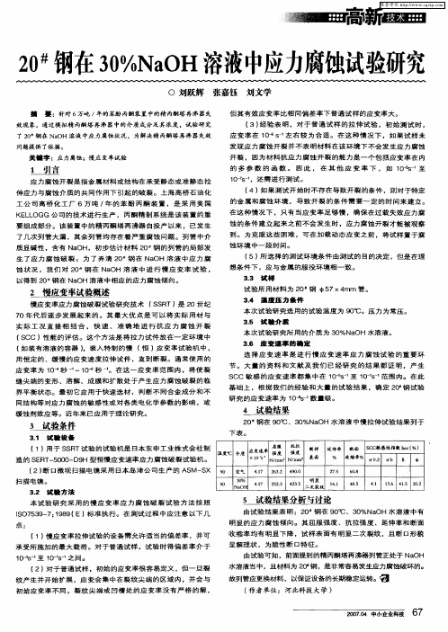
效现 象。通过模 拟精 丙酮塔再 沸器 中的介 质成分及其 浓度 ,试验研 究
了2 # 0 钢在 N O a H溶 液中应力腐蚀状况 ,为解 决精 丙酮塔再沸 器失效
问题 提 供 了依 据 。
应变率在 1^S Oe 一左 右 较 为 合 适 。在 这 种 情 况 下 ,如 果试 样 未
选 择 应 变 速 率 是 进 行 慢 应 变 速 率 应 力 腐 蚀 试 验 的 重 要 环
节 。 大 量 的 资 料 和 文 献 及 我 们 已 经 研 究 的 结 果 都 证 明 ,产 生
应 变 率 为 1 一秒 ~~1 秒 ~ 在 这 一 应 变 率 范 围 内 ,将 使 裂 O O 。 缝 尖 端 的 变 形 、溶解 、成 膜 和 扩 散 处 于 产 生 应 力 腐 蚀 破 裂 的 临
界 平 衡 状 态 。 最 初 它 应 用 于 快 速 选 材 ,判 断 不 同合 金 成 分 和 不 同 结 构 等对 应 力 腐蚀 的 敏 感 性 或 对 各 类 电化 学 参 数 的影 响 ,或 缓 蚀剂 效 应 等 。 近 年 来 已应 用于 理 论 研 究 。
S CC敏 感 的 应 变速 率 都 集 中 在 1- 0% 至 1 - 一范 围 内 。在 此 07 s
实 际 工 况 直 接 相 结 合 ,快 速 、 准 确 地 进 行 抗 应 力 腐 蚀 开 裂 ( C 能 的 评 估 。这 个 方 法 是 将 拉 力试 件 放 在 一 定 环 境 中 S C J性
本 次 试 验 研 究 选 用 的试 验 温 度 为 9  ̄ 压 力 为 常 压 。 0C。
33 试 样 . 试 验 所 用 材 料 为 2 钢 由5 0 7X4 mm 管 。
34 沮 度 压 力条 件 .
ASTM G39 - 99(2011)
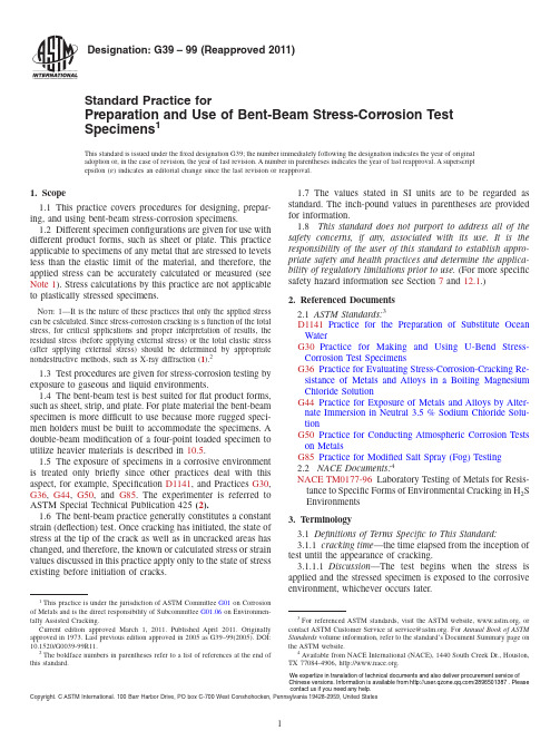
Designation:G39–99(Reapproved 2011)Standard Practice forPreparation and Use of Bent-Beam Stress-Corrosion Test Specimens 1This standard is issued under the fixed designation G39;the number immediately following the designation indicates the year of original adoption or,in the case of revision,the year of last revision.A number in parentheses indicates the year of last reapproval.A superscript epsilon (´)indicates an editorial change since the last revision or reapproval.1.Scope1.1This practice covers procedures for designing,prepar-ing,and using bent-beam stress-corrosion specimens.1.2Different specimen configurations are given for use with different product forms,such as sheet or plate.This practice applicable to specimens of any metal that are stressed to levels less than the elastic limit of the material,and therefore,the applied stress can be accurately calculated or measured (see Note 1).Stress calculations by this practice are not applicable to plastically stressed specimens.N OTE 1—It is the nature of these practices that only the applied stress can be calculated.Since stress-corrosion cracking is a function of the total stress,for critical applications and proper interpretation of results,the residual stress (before applying external stress)or the total elastic stress (after applying external stress)should be determined by appropriate nondestructive methods,such as X-ray diffraction (1).21.3Test procedures are given for stress-corrosion testing by exposure to gaseous and liquid environments.1.4The bent-beam test is best suited for flat product forms,such as sheet,strip,and plate.For plate material the bent-beam specimen is more difficult to use because more rugged speci-men holders must be built to accommodate the specimens.A double-beam modification of a four-point loaded specimen to utilize heavier materials is described in 10.5.1.5The exposure of specimens in a corrosive environment is treated only briefly since other practices deal with this aspect,for example,Specification D1141,and Practices G30,G36,G44,G50,and G85.The experimenter is referred to ASTM Special Technical Publication 425(2).1.6The bent-beam practice generally constitutes a constant strain (deflection)test.Once cracking has initiated,the state of stress at the tip of the crack as well as in uncracked areas has changed,and therefore,the known or calculated stress or strain values discussed in this practice apply only to the state of stress existing before initiation of cracks.1.7The values stated in SI units are to be regarded as standard.The inch-pound values in parentheses are provided for information.1.8This standard does not purport to address all of the safety concerns,if any,associated with its use.It is the responsibility of the user of this standard to establish appro-priate safety and health practices and determine the applica-bility of regulatory limitations prior to use.(For more specific safety hazard information see Section 7and 12.1.)2.Referenced Documents 2.1ASTM Standards:3D1141Practice for the Preparation of Substitute Ocean WaterG30Practice for Making and Using U-Bend Stress-Corrosion Test SpecimensG36Practice for Evaluating Stress-Corrosion-Cracking Re-sistance of Metals and Alloys in a Boiling Magnesium Chloride SolutionG44Practice for Exposure of Metals and Alloys by Alter-nate Immersion in Neutral 3.5%Sodium Chloride Solu-tionG50Practice for Conducting Atmospheric Corrosion Tests on MetalsG85Practice for Modified Salt Spray (Fog)Testing 2.2NACE Documents:4NACE TM0177-96Laboratory Testing of Metals for Resis-tance to Specific Forms of Environmental Cracking in H 2S Environments 3.Terminology3.1Definitions of Terms Specific to This Standard:3.1.1cracking time —the time elapsed from the inception of test until the appearance of cracking.3.1.1.1Discussion —The test begins when the stress is applied and the stressed specimen is exposed to the corrosive environment,whichever occurs later.1This practice is under the jurisdiction of ASTM Committee G01on Corrosion of Metals and is the direct responsibility of Subcommittee G01.06on Environmen-tally Assisted Cracking.Current edition approved March 1,2011.Published April 2011.Originally approved in st previous edition approved in 2005as G39–99(2005).DOI:10.1520/G0039-99R11.2The boldface numbers in parentheses refer to a list of references at the end of this standard.3For referenced ASTM standards,visit the ASTM website,,or contact ASTM Customer Service at service@.For Annual Book of ASTM Standards volume information,refer to the standard’s Document Summary page on the ASTM website.4Available from NACE International (NACE),1440South Creek Dr.,Houston,TX 77084-4906,.Copyright.C ASTM International.100Barr Harbou r Drive,PO box C-700West Conshohocken,Pennsylvania 19428-2959,United StatesWe expertize in translation of technical documents and also deliver procurement service of Chinese versions. Information is available from /2896501387 . Please contact us if you need any help.3.1.1.2Discussion—The specimen is considered to have failed when cracks are detected.Presence of cracks can be determined with or without optical,mechanical,or electronic aids.However,for meaningful interpretation,comparisons should be made only among tests employing crack detection methods of equivalent sensitivity.3.1.2stress-corrosion cracking—a cracking process requir-ing the simultaneous action of a corrodent and sustained tensile stress.This excludes corrosion-reduced sections that fail by fast fracture.It also excludes intercrystalline or transcrystalline corrosion which can disintegrate an alloy without either applied or residual stress.4.Summary of Practice4.1This practice involves the quantitative stressing of a beam specimen by application of a bending stress.The applied stress is determined from the size of the specimen and the bending deflection.The stressed specimens then are exposed to the test environment and the time required for cracks to develop is determined.This cracking time is used as a measure of the stress-corrosion resistance of the material in the test environment at the stress level utilized.5.Significance and Use5.1The bent-beam specimen is designed for determining the stress-corrosion behavior of alloy sheets and plates in a variety of environments.The bent-beam specimens are de-signed for testing at stress levels below the elastic limit of the alloy.For testing in the plastic range,U-bend specimens should be employed(see Practice G30).Although it is possible to stress bent-beam specimens into the plastic range,the stress level cannot be calculated for plastically-stressed three-andfour-point loaded specimens as well as the double-beam specimens.Therefore,the use of bent-beam specimens in the plastic range is not recommended for general use.6.Apparatus6.1Specimen Holders—Bent-beam specimens require a specimen holder for each specimen,designed to retain the applied stress on the specimen.Typical specimen holder configurations are shown schematically in Fig.1.N OTE2—The double-beam specimen,more fully described in10.5,is self-contained and does not require a holder.N OTE3—Specimen holders can be modified from the constant defor-mation type shown in Fig.1to give a constant-load type of stressing.For instance,the loading bolt can be supplanted by a spring or deadweight arrangement to change the mode of loading.6.1.1The holder shall be made of a material that would withstand the influence of the environment without deteriora-tion or change in shape.N OTE4—It should be recognized that many plastics tend to creep when subjected to sustained loads.If specimen holders or insulators are made of such materials,the applied stress on the specimen may change appreciably with time.By proper choice of holder and insulator materials,however, many plastics can be used,especially in short-time tests.6.1.2When the stress-corrosion test is conducted by immer-sion in an electrolyte,galvanic action between specimen and holder(or spacer)shall be prevented(see Note5).This is accomplished by(1)making the holder of the same material as the individual specimens,(2)inserting electrically insulating materials between specimen and holder at all points of contact (see Note4),(3)making the entire holder out of a nonmetallic material(see Note4),or(4)coating the holder with an electrically nonconducting coating that effectively prevents contact between holder and electrolyte.6.1.3Crevice corrosion may occur in an electrolyte at contact points between specimen and holder(or spacer).In these instances the critical areas should be packed with a hydrophobicfiller(such as grease or wax).N OTE5—In atmospheres(gas)galvanic action between specimen and holder either does not exist or is confined to a very small area as experienced in outdoor exposure tests.6.2Stressing Jigs—Three-point and four-point loaded specimen holders,Fig.1(b and c),contain a stressing feature in the form of a loading screw.To stress two-point loaded specimens(Fig.1(a)),a separate stressing jig shall be used.A convenient stressing jig is shown in Fig.2.N OTE6—The double-beam specimen,described in10.5,requires a mechanical or hydraulic stressing frame(a universal tension testing machine can also be used)as well as welding equipment.6.3Deflection Gauges—Deflection of specimens is deter-mined by separate gages or by gages incorporated in a loading apparatus as shown in Fig.3.In designing a deflection gageto FIG.1Schematic Specimen and HolderConfigurationssuit individual circumstances care must be taken to reference the deflection to the proper support distance as defined in 10.2-10.5.7.Hazards7.1Bent-beam specimens made from high-strength materi-als may exhibit high rates of crack propagation and a specimen may splinter into several pieces.Due to high stresses in a specimen,these pieces may leave the specimen at high velocity and can be dangerous.Personnel installing and examining specimens should be cognizant of this possibility and be protected against injury.8.Sampling8.1Test specimens shall be selected so that they represent the material to be tested.In simulating a service condition,the direction of load application in the specimen shall represent theanticipated loading direction in service with respect to process-ing conditions,for example,rolling direction.8.2Paragraphs 9.4and 9.5deal specifically with specimen selection as related to the original material surface.9.Test Specimen9.1The bent-beam,stress-corrosion specimens shall be flat strips of metal of uniform,rectangular cross section,and uniform thickness.9.2The identification of individual specimens should be permanently inscribed at each end of the specimen because this is the area of lowest stress and cracking is not expected to be initiated by the identification markings.If stenciling is used for identification,this shall be done only on softened material before any hardening heat treatments to prevent cracking in the stenciled area.Care must be taken to prevent the identification from being obliterated by corrosion.9.3Mechanical properties should be determined on the same heat-treatment lot from which stress-corrosion specimens are obtained.9.4The specimens can be cut from sheet or plate in such a fashion that the original material surface is retained.This procedure is recommended when it is desired to include the effect of surface condition in the test.9.5If,however,it is desired that surface conditions should not influence the test results of several materials with different surface conditions,the surfaces of all specimens must be prepared in the same way.It is recommended that grinding or machining to a surface finish of at least 0.7µm (30µin.)and to a depth of at least 0.25mm (0.01in.)be utilized for surface preparation.It is desirable to remove the required amount of metal in several steps by alternately grinding opposite surfaces.This practice minimizes warpage due to residual stresses caused by machining.All edges should be similarly ground or machined to remove cold-worked material from previous shearing.Chemical or electrochemical treatments that produce hydrogen on the specimen surface must not be used on materials that may be subject to embrittlement by hydrogen or that react with hydrogen to form a hydride.9.6Immediately before stressing,the specimens should be degreased and cleaned to remove contamination that occurred during specimen preparation.Only chemicals appropriate for the given metal or alloy should be used.Care must be exercised not to contaminate cleaned specimens.Also,it is suggested that specimens be examined for cracks before exposure to the test environment.10.Stress Calculations10.1The equations given in this section are valid only for stresses below the elastic limit of the material.At stresses above the elastic limit,but below the engineering yield strength (0.2%offset)only a small error results from use of the equations (see Note 1).The equations must not be used above the yield strength of the material.The following paragraphs give relationships used to calculate the maximum longitudinal stress in the outer fibers of the specimen convex surface.Calculations for transverse stress or edge-to-edge variation of longitudinal stress are not given;the specimen dimensions are chosen to minimize these stresses consistent withconvenientFIG.2Stressing Jig and Two-Point Loaded Specimen with Holder(approximately 1⁄4actualsize)FIG.3Specimen Loading Apparatus for Three-Point LoadedBeam Specimens with Integral DeflectionGageuse of the specimens.The specimen dimensions given here can be modified to suit specific needs.However,if this is done,the approximate specimen proportions should be preserved to give a similar stress distribution (for instance,if the length is doubled the width should be doubled also).10.1.1When specimens are tested at elevated temperatures,the possibility of stress relaxation should be investigated.Relaxation can be estimated from known creep data for the specimen,holder,and insulating materials.Differences in thermal expansion also should be considered.10.1.2The applied stress is determined by specimen dimen-sions and the amount of bending deflection.Thus,the errors in the applied stress are related to those inherent in the use of measuring instruments (micrometers,deflection gages,strain gages,and so forth).For the two-point loaded specimens,most measured values lie within 5%of the values calculated in accordance with the procedures given in 10.2.1-10.2.3,as reported by Haaijer and Loginow (4).The calculated stress applies only to the state of stress before initiation of cracks.Once cracking is initiated,the stress at the tip of the crack,as well as in uncracked areas,has changed.10.2Two-Point Loaded Specimens —This specimen can be used for materials that do not deform plastically when bent to (L −H)/H =0.01(see section 10.2.5).The specimens shall be approximately 25by 254-mm (1-by 10-in.)flat strips cut to appropriate lengths to produce the desired stress after bending as shown in Fig.1(a ).10.2.1Calculate the elastic stress in the outer fiber at midlength of the two-point loaded specimens from relation-ships derived from a theoretically exact large-deflection analy-sis (4),as follows:´54~2E 2K !F k 222E 2K 12S tHD Gt H(1)and~L 2H !/H 5[K /2E 2K !#21(2)where:L =length of specimen,H =distance between supports (holder span),t =thickness of specimen,´=maximum tensile strain,K =*0p /2(1−k 2sin 2z )−1/2d z (complete elliptic integral ofthe first kind),E =*0p /2(1−k 2sin 2z )1/2d z (complete elliptic integral of thesecond kind),k =sin u /2,u =maximum slope of the specimen,that is,at the end ofthe specimen,andz =integration parameter (4).10.2.2The mathematical analysis establishes that Eq 1and Eq 2define the relationship between the strain ´and (L −H)/H in parameter form.The common parameter in these equations is the modulus k of the elliptic integrals.Thus,the following procedure can be used to determine the specimen length L that is required to produce a given maximum stress s :10.2.2.1Divide the stress s by the modulus of elasticity E m to determine the strain ´.´5s /E m10.2.2.2From Eq 1determine the value of k corresponding to the required value of ´.10.2.2.3By using appropriate values of k ,evaluate Eq 2for L .To facilitate calculations,a computer can be used to generate a table for a range of strain ´and H/t with resultant values of (L −H)/H .10.2.3Calculate the deflection of the specimen as follows:y /H 5k /~2E 2K !(3)where:y =maximum deflection.The other quantities are given in 10.2.1.This relationship can be used as a simple check to ensure that the maximum stress does not exceed the proportional limit.If it should exceed the proportional limit,the measured deflection will be greater than that calculated from Eq 3.10.2.4As an alternative method the following approximate relationship can be used for calculating specimen length:L 5~ktE /s !sin 21~H s /ktE !(4)where:L =specimen length,s =maximum stress,E =modulus of elasticity,H =holder span,t =thickness of specimen,and k = 1.280,an empirical constant.This equation can be solved by computer,by trial and error,or by using a series expansion of the sine function.Eq 4shall be used only when the quantity (H s /ktE)is less than 1.0.10.2.5Choose specimen thickness and length and holder span to obtain a value for (L −H)/H of between 0.01and 0.50,thus keeping the error of stress within acceptable limits.A specimen thickness of about 0.8to 1.8mm (0.03to 0.07in.)and a holder span of 177.8to 215.9mm (7.00to 8.50in.)has been very convenient when working with very high strength steels and aluminum alloys with applied stresses ranging from about 205MPa (30ksi)for aluminum to 1380MPa (200ksi)for steel.The specimen dimensions given here can be modified to suit specific needs.However,if this is done,approximate dimensional proportions shall be preserved.10.2.6In two-point loaded specimens the maximum stress occurs at midlength of the specimen and decreases to zero at specimen ends.10.2.7The two-point loaded specimen is preferred to three-point loaded specimens because in many instances crevice corrosion of the specimen occurs at the central support of the three-point loaded specimen.Since this corrosion site is very close to the point of highest tension stress,it may cathodically protect the specimen and prevent possible crack formation or cause hydrogen embrittlement.Furthermore,the pressure of the central support at the point of highest load introduces biaxial stresses at the area of contact and could introduce tension stresses where normally compression stresses are present.N OTE 7—Occasionally two-point loaded specimens having a nonuni-form cross section are used for special purposes.A description of such a specimen is given by Wilson and Spier (5).10.3Three-Point Loaded Specimens—The specimen shall be aflat strip typically25to51-mm(1to2-in.)wide and127 to254-mm(5to10-in.)long.The thickness of the specimen is usually dictated by the mechanical properties of the material and the product form available.Support the specimen at the ends and bend the specimen by forcing a screw(equipped with a ball or knife-edge tip)against it at the point halfway between the end supports in a fashion shown in Fig.1(b).The specimen dimensions given here can be modified to suit specific needs. However,if this is done,approximate dimensional proportions shall be preserved.10.3.1Calculate the elastic stress at midspan in the outer fibers of three-point loaded specimens from the relationship:s56Ety/H2(5) where:s=maximum tensile stress,E=modulus of elasticity,t=thickness of specimen,y=maximum deflection,andH=distance between outer supports.10.3.2The above relationship is based on small deflections (y/H less than0.1).In sheet-gage,bent-beam specimens the deflections are usually large,and thus,the relationship is only approximate.To obtain more accurate stress values,use a prototype specimen,equipped with strain gages,for calibra-tion.This prototype should have the same dimensions as the test specimens and should be stressed in the same way. 10.3.3In three-point loaded specimens the maximum stress occurs at midlength of the specimen and decreases linearly to zero at the outer supports.10.3.4For limitation in the use of three-point loaded speci-mens see10.2.7.10.4Four-Point Loaded Specimens—The specimen shall be aflat strip typically25to51-mm(1to2-in.)wide and127to 254-mm(5to10-in.)long.The thickness of the specimen is usually dictated by the mechanical properties of the material and the product form available.Support the specimen at the ends and bend the specimen by forcing two inner supports against it in a fashion shown in Fig.1(c).The two inner supports shall be located symmetrically around the midpoint between the outer supports.The specimen dimensions given here can be modified to suit specific needs.However,if this is done,approximate dimensional proportions shall be preserved.10.4.1Calculate the elastic stress for the midportion of the specimen(between contact points of the inner support)in the outerfibers of four-point loaded specimens from the following relationship:s512Ety/~3H224A2!(6) where:s=maximum tensile stress,E=modulus of elasticity,t=thickness of specimen,y=maximum deflection(between outer supports),H=distance between outer supports,andA=distance between inner and outer supports.The dimensions are often chosen so that A=H/4.10.4.2An alternative method of calculating the elastic stress between the inner supports is as follows:s54Ety8/h2(7) where:h=distance between inner supports,andy8=deflection between inner supports.(This equation is a special case of10.4.1when A=0.) 10.4.3The above relationships are based on small deflec-tions(y/H less than0.1).In sheet-gage bent-beam specimens the deflections are usually large,and thus,the relationships are only approximate.To obtain more accurate stress values,use for calibration a prototype specimen equipped with strain gages.This prototype specimen should have the same dimen-sions as the test specimens and should be stressed in the same way.10.4.4In four-point loaded specimens the maximum stress occurs between the contact points with the inner supports;in this area the stress is constant.From the inner supports the stress decreases linearly toward zero at the outer supports. 10.5Double-Beam Specimen—The specimen shall consist of twoflat strips25to51-mm(1to2-in.)wide and127to 254-mm(5to10-in.)long.Bend the strips against each other over a centrally located spacer until both ends of the specimens touch.Hold them in this position by welding the ends together as shown in Fig.1(d)(see Note8).An equivalent procedure for bolted specimens is described on pp.319–321of Ref(2).N OTE8—If the test is to be conducted in an electrolyte,the spacer shall be made of the same material as the specimen(or of an electrically nonconducting material such as glass,ceramic,and so forth)to prevent galvanic action between specimen and spacer.See also6.1.2and Note4 and Note5.10.5.1Calculate the elastic stress for the midportion of the specimen(between contact points of the spacer)in the outer fibers of the doublebeam specimens from the following rela-tionship:s53EtsH2@12~h/H!#@11~2h/H!#(8)where:s=maximum tensile stress,E=modulus of elasticity,t=thickness of specimen strip,s=thickness of spacer,H=see Fig.1(d),andh=length of spacer.10.5.2When the length of the spacer h is chosen so that H=2h the equation in10.5.1is simplified to:s53Ets/H210.5.3The above relationships are based on small deflec-tions(s/H being less than0.2).In sheet-gage bent-beam specimens the deflections are usually large,and thus,the relationships are only approximate.To obtain more accurate stress values,use a prototype specimen,equipped with strain gages,for calibration.The prototype specimen should have the same dimensions as the test specimens and should be stressed in the sameway.10.5.4In double-beam specimens the maximum stress oc-curs between the contact points with the spacer;in this area the stress is constant.From the contact with the spacer the stress decreases linearly toward zero at the ends of specimens. 11.Choice of Test Conditions11.1The purpose of stress-corrosion testing is to simulate on a small scale the conditions(materials,stress,and environ-ment)that exist in an engineering application.The stresses in an engineering structure can be varied between operational (design)stresses and residual stresses(from heat treatment or fabrication).Residual stresses are frequently the more impor-tant,primarily because current design practices and close control of processes have kept operational stresses well below the yield strength of the metal in use.On the other hand, magnitude and direction of residual stresses frequently are difficult to predict and also difficult to measure.Depending on the degree of restraint,residual stresses may even exceed the initial yield strength of the material.11.2Generally stress-corrosion testing falls into two broad categories:(1)evaluation of materials for a specific applica-tion,and(2)comparison of the relative behavior of several materials or environments.11.2.1To evaluate materials for specific applications,the testing conditions should be representative of the most severe conditions to which the materials would be subjected in service.Testing at nominal or design conditions could be misleading.An engineering structure,because of residual stresses,is expected to be stressed to its yield strength at some points even if the design stress for that structure is appreciably below yield strength.Thus,the use of the elastically stressed bent-beam specimens for materials evaluation is of limited value.11.2.2To compare materials or environments for relative stress-corrosion behavior,the test conditions may be only severe enough to produce varying degrees of cracking in the alloys of interest,in mechanical or thermal treatments used,or in sensitivity to specific environments investigated.By testing a set of specimens at a series of stress levels,the stress dependence of alloys can be assessed.The bent-beam speci-men is very well suited for establishing the relative merits of several alloys for the relative severity of several environments.11.3Ideally,the environmental test conditions should be the same that would prevail in the intended use of the alloys.In choosing a set of test conditions,it is important that they (environment and stress)be well defined and reproducible.A detailed discussion is given by Loginow(6).11.4The presence of a machined notch in the middle of the tension side of a bent beam will induce a severe triaxial stress state at the root of the notch.The actual bending stress there will be greater by a concentration factor dependent on the notch geometry,than the minimal test stress,and generally, may be expected to be in the range of plastic stain.Advantages of such a notched specimen include the probable localized cracking in the notch and an acceleration of failure.However, unless directly related to practical conditions of usage,mis-leading failures may ensue.11.4.1Another type of stress concentration at the site of two drilled holes located half way between the end supports of a three-point loaded bent beam has been used in the evaluation of metals for oilfield equipment.Details on the preparation and use of this specimen are described in NACE TM0177-96. Laboratory test data for carbon and low-alloy steels have been found to correlate withfield data(7).12.Specimen Exposure12.1Expose the stressed specimens to the environment (gaseous or liquid)of interest.This can be accomplished by mounting the specimen holders on appropriate racks and exposing the entire rack to the environment.A typical atmo-spheric exposure rack is shown in Fig.4.As noted in7.1, bent-beam specimens may break violently and thus cause injury.To protect personnel and to prevent specimen loss,drill holes in specimen ends and holders and secure the specimens by wires to their holders.12.2Determination of cracking time is a subjective proce-dure involving visual examination that under someconditions FIG.4Bent-Beam Specimens on Atmospheric ExposureRack。
不锈钢沸腾氯化镁应力腐蚀试验
不锈钢沸腾氯化镁应力腐蚀试验
不锈钢在氯离子的存在下,在高温和高压环境中会出现应力腐蚀现象。
氯离子可以进入不锈钢晶界并与晶体中的钢铁原子发生反应,形成氯化物。
在高温高压的作用下,氯化物会引起钢中的应力集中,导致晶格扩张和晶界腐蚀。
这种应力腐蚀破坏会导致不锈钢的力学性能下降,甚至导致不锈钢的断裂和破损。
沸腾氯化镁应力腐蚀试验是一种用于评估不锈钢在高温高压下抵抗应力腐蚀性能的试验方法。
在试验中,将不锈钢试样置于含有氯化镁的高温高压环境中,通常会加入一定的应力,例如通过拉伸试样。
通过观察不锈钢试样的外观变化、测量应力腐蚀裂纹的长度和宽度等方式,评估不锈钢在沸腾氯化镁环境下的耐蚀性能。
沸腾氯化镁应力腐蚀试验可以用于研究不同不锈钢材料的应力腐蚀性能差异,评估不同工艺条件下不锈钢材料的耐腐蚀性能,并指导不同领域的工程设计和材料选择。
应力腐蚀试验操作规程
应力腐蚀试验操作规程应力腐蚀试验(Stress Corrosion Cracking,SCC)是一种评价材料在应力作用下腐蚀敏感性的方法。
它可用于评估材料的工程性能和耐久性,尤其是在温度和湿度环境中。
以下是应力腐蚀试验的操作规程。
一、试验前准备1.选择试验材料和试样,并制备好试样,确保其符合要求。
2.准备好试验设备,包括应力装载设备、试样架和腐蚀介质等。
3.清洁试样和试验设备,确保无表面污染。
二、试验设备调试1.检查试验设备的安全性和可靠性,确保其能正常工作。
2.测试应力装载设备的标定和准确性,确保能正确施加设定的应力。
三、试样安装1.安装试样于试验设备中,并进行必要的校准。
2.确保试样能受到均匀的应力加载,并避免应力局部集中。
四、试验参数设定1.根据试验需求,确定试验的温度、湿度和应力等级。
2.设定试验时间,根据试验材料和环境的特性来确定。
五、试验开始1.开始应力腐蚀试验,并定期记录试验条件和观察试样情况。
2.进行必要的中期检查和维护,确保试验过程的稳定性。
六、试验结束1.达到设定的试验时间后,停止试验,并关闭试验设备。
2.取出试样,并进行表面检查和观察。
七、结果分析1.根据试样的表面情况和试验参数,判断试样是否产生了应力腐蚀开裂。
2.对试验结果进行统计和分析,给出相应的评价和建议。
八、资料整理1.将试验数据整理成报告,包括试验参数、观察结果和分析结论等。
2.保存好试样和试验设备等相关资料,以备后续的研究和使用。
总结:应力腐蚀试验是一项重要的材料评价方法,其可用于评估材料在应力作用下的腐蚀敏感性。
通过执行以上的操作规程,能够确保试验的准确性和可靠性,为材料性能的评估和材料选择提供有力的支持。
慢拉伸应力腐蚀试验测试标准

慢拉伸应力腐蚀试验测试标准慢拉伸应力腐蚀试验(Slow Strain Rate Testing,简称SSRT)是一种常用的材料力学性能测试方法,主要用于评估材料在应力腐蚀环境中的抗腐蚀性能。
本文将介绍慢拉伸应力腐蚀试验的测试标准。
一、试验目的慢拉伸应力腐蚀试验的主要目的是评估材料在应力腐蚀环境中的抗腐蚀性能,包括抗氢脆性、抗应力腐蚀开裂性等方面。
二、试验原理慢拉伸应力腐蚀试验通过施加一定的应变速率和应力水平,使试样在应力腐蚀介质中进行慢速拉伸,以模拟材料在实际使用条件下的受力状态。
通过观察试样的断口形貌、测量其断裂应变等参数,可以评估材料在应力腐蚀环境中的抗腐蚀性能。
三、试验装置慢拉伸应力腐蚀试验通常采用电化学工作站进行测试。
电化学工作站包括电化学池、拉伸装置、电化学测量系统等组成部分。
其中,电化学池用于容纳试样和腐蚀介质,拉伸装置用于施加拉伸载荷,电化学测量系统用于监测试样的电化学行为。
四、试样制备慢拉伸应力腐蚀试验的试样通常为平行四边形形状,尺寸一般为长25mm、宽5mm、厚0.5mm。
试样表面应进行必要的打磨和清洗处理,以确保试样表面的光洁度和无杂质。
五、试验步骤1. 将试样放入电化学池中,并加入适量的腐蚀介质。
2. 设定拉伸速率和应力水平,并开始拉伸测试。
3. 实时监测试样的电化学行为,包括电位、电流等参数。
4. 在达到一定的拉伸应变后停止测试。
5. 取出试样,观察其断口形貌,并进行断裂应变测量。
六、试验结果分析通过观察试样的断口形貌和测量其断裂应变等参数,可以评估材料在应力腐蚀环境中的抗腐蚀性能。
常见的分析方法包括断口分析、断裂应变分析等。
七、注意事项1. 选择合适的腐蚀介质和拉伸速率,以模拟实际使用条件。
2. 保持试样表面的光洁度和无杂质,以减小外界因素对测试结果的影响。
3. 注意安全操作,避免发生意外事故。
八、总结慢拉伸应力腐蚀试验是一种常用的材料力学性能测试方法,可以评估材料在应力腐蚀环境中的抗腐蚀性能。
慢拉伸应力腐蚀标准

慢拉伸应力腐蚀标准一、试验条件1.试验环境:试验应在恒温、恒湿的环境中进行,以保证试验结果的准确性。
2.试验溶液:试验溶液应根据实际应用场景选择,如模拟海水、酸碱溶液等。
3.试验温度:试验温度应根据实际应用场景选择,一般为室温至50℃。
4.试验时间:试验时间应根据实际应用场景选择,一般为24小时至数天。
二、试样制备1.材料选择:试样应选择具有代表性的材料,如不锈钢、碳钢等。
2.形状与尺寸:试样应具有标准的形状与尺寸,以便进行对比试验。
3.表面处理:试样表面应平整光滑,无划痕、毛刺等缺陷,以保证试验结果的准确性。
4.加载装置:试样应安装有慢拉伸应力腐蚀试验的加载装置,以保证在试验过程中对试样施加一定的应力。
三、试验程序1.预处理:将试样放置在试验环境中,进行一定时间的预处理,以适应环境条件。
2.加载应力:按照规定程序对试样施加一定的应力,应力值应按照相关标准进行设定。
3.保持时间:在施加应力后,保持一定时间,以观察试样的变化情况。
4.卸载应力:在试验结束后,将试样卸载应力,以便进行后续观察。
5.观察与记录:观察试样的变化情况,并记录相关数据。
四、试验结果评定1.根据试验结果绘制应力腐蚀曲线,以评估试样的耐应力腐蚀性能。
2.根据观察结果判断试样是否发生断裂、变形等异常现象。
3.根据试验数据计算有关力学性能参数,如弹性模量、屈服强度等。
4.将试验结果与标准值进行对比,判断试样的耐应力腐蚀性能是否符合要求。
5.对试验结果进行分析,评估材料在实际应用中的耐应力腐蚀性能。
五、试验报告1.报告内容应包括试验名称、试验目的、试验条件、试样信息、试验程序、试验结果评定等内容。
2.报告应以严谨、客观的语言描述试验过程和结果,不得夸大或缩小事实。
3.报告中应附有试验曲线图和数据表等相关资料,以便读者更好地了解试验结果。
铝应力腐蚀试验方法
铝应力腐蚀试验方法介绍铝及其合金在应力环境下容易发生腐蚀现象,这种情况被称为应力腐蚀。
应力腐蚀会导致铝材料的力学性能下降甚至发生失效,对铝合金材料的使用和应用造成很大的影响。
因此,进行铝应力腐蚀试验是非常重要的。
本文将介绍铝应力腐蚀试验的方法,包括试样准备、应力施加、腐蚀液选择等方面内容,以帮助读者全面了解铝应力腐蚀试验的流程和注意事项。
试样准备在进行铝应力腐蚀试验之前,首先需要准备试样。
试样的选择要符合实际应用情况,并满足试验需求。
通常情况下,可以选择片状试样或者是圆柱形试样。
试样的制备需要注意以下几点: 1. 保证试样的表面光洁度,避免表面存在油污、氧化物等杂质影响试验结果。
2. 试样尺寸应符合试验标准要求,以确保试验结果的可靠性和可重复性。
3. 试样经过清洗和除油处理后,应立即进行试验,避免试样再次被污染和氧化。
应力施加在进行铝应力腐蚀试验时,需要施加一定大小的应力。
应力的施加可以通过拉伸、弯曲等方式实现。
根据试验需求和试样形状的不同,选择合适的应力施加方式。
为了确保应力的准确施加,需要注意以下几点: 1. 在施加应力之前,需要测量试样的初始尺寸,以便在试验过程中准确计算应力的影响。
2. 选择适当的应力施加速率,避免过快或过慢导致试验结果不准确。
3. 应控制应力的大小,使其达到设计要求,并保持稳定状态。
腐蚀液选择选择合适的腐蚀液是进行铝应力腐蚀试验的关键。
腐蚀液的组成和浓度会对试验结果产生重要影响。
通常情况下,选择含有氯离子的酸性溶液作为腐蚀液。
以下是几种常用的腐蚀液选择: 1. 硝酸溶液:可以产生氧化性腐蚀作用,常用于检测铝合金的抗腐蚀性能。
2. 氯化钠溶液:可以模拟海洋环境中的腐蚀情况,常用于测试铝合金在海洋环境中的腐蚀性能。
3. 硫酸溶液:可以模拟工业环境中的腐蚀情况,常用于测试铝合金在工业环境中的腐蚀性能。
选择腐蚀液时需要考虑以下几点: 1. 腐蚀液的组成应与实际应用环境相符,以使试验结果更具可靠性和实用性。
scc腐蚀试验标准

SCC腐蚀试验标准1. 引言SCC(应力腐蚀开裂)是金属材料在应力作用下,由于与腐蚀介质发生特定的相互作用而产生的一种腐蚀破坏形式。
为了评估材料的抗SCC能力,进行SCC腐蚀试验是十分重要的。
本文将介绍SCC腐蚀试验的标准和操作规程。
2. 试验标准概述SCC腐蚀试验标准主要包括两个方面的内容:试验方法和试验要求。
试验方法指导试验操作的步骤和工艺,而试验要求则是规定试验样品及试验条件。
以下是一些常见的SCC腐蚀试验标准:•ASTM G36:腐蚀应力开裂试验方法标准;•ASTM G39:用环形应力-应变曲线进行腐蚀应力裂纹扩展试验;•NACE TM 0177:用缓变应力腐蚀环境进行SCC试验的标准实施规程;•NACE TM 0187:用快速缓慢应变应力腐蚀环境进行SCC试验的标准实施规程。
3. 试验方法3.1 准备试样根据试验要求,准备合适的试样。
试样可以是平板状,也可以是管状等不同形状。
确保试样表面光洁、无明显损伤,并清洗干净。
视不同试验需求,可以通过机械或化学方法进行清洗处理。
3.2 试验设备根据试验标准的要求,选择合适的试验设备。
设备主要包括:应力腐蚀试验装置、控制系统、电化学工作站等。
确保试验设备高度自动化,能够准确控制温度、应力、腐蚀介质等参数。
3.3 试验操作步骤1.将试样固定于试验装置上,并确保试样与电极等接触良好;2.设置试验温度、应力和腐蚀介质;3.开始实施试验,记录试验过程中的温度、应力和时间等信息;4.持续观察试样的表面变化和裂纹扩展情况;5.试验结束后,将试样从装置上取下,进行表面分析。
4. 试验要求试验要求主要包括试验样品、试验条件和试验结果分析等。
4.1 试验样品根据需要选择代表性的样品进行试验。
样品应符合试验标准中的要求,尺寸、材料和表面处理等应保持一致性,以保证试验结果的可靠性。
4.2 试验条件试验条件包括温度、应力和腐蚀介质等。
根据试验目的,确定适宜的试验条件。
试验过程中,应严格控制试验参数,记录各项参数变化,以便后续数据分析。
不锈钢应力腐蚀测试标准

不锈钢应力腐蚀测试标准一、试验条件1. 试验环境:试验应在干燥、无尘、无强烈震动和电磁干扰的环境中进行。
2. 温度和湿度:试验温度应在25℃±5℃范围内,湿度应控制在50±10%。
3. 试验介质:试验介质应根据实际应用环境选择,如3.5%NaCl溶液、海水等。
4. 试验周期:应力腐蚀试验周期应根据产品应用条件和实际需要确定,一般不少于72小时。
二、试样准备1. 试样材料:试样应采用不锈钢材料,表面应光滑、无划痕、无毛刺。
2. 试样尺寸:试样尺寸应符合相关标准要求,一般应为100mm×100mm×3mm。
3. 试样预处理:试样在试验前应进行打磨、清洗等预处理,以去除表面污染物和氧化层。
4. 应力加载:试样应进行应力加载,加载方式可采用拉伸应力、压缩应力或弯曲应力等,加载量应根据实际应用情况确定。
三、试验溶液1. 溶液配制:根据试验要求选择合适的腐蚀介质,如3.5%NaCl溶液、海水等,并按照相关标准配制。
2. 溶液维护:试验过程中应定期更换试验溶液,以保持其浓度和性质稳定。
3. 溶液温度控制:试验过程中应控制试验溶液的温度在规定范围内,以保证试验结果的准确性。
四、试验程序1. 将试样放入试验溶液中,保持垂直状态。
2. 启动试验设备,使试样在设定的应力条件下进行腐蚀试验。
3. 记录试样的腐蚀过程,如裂纹产生时间、裂纹扩展情况等。
4. 定期检查试样表面状态,如出现裂纹应记录其尺寸、位置等信息。
5. 在试验周期结束后取出试样,清洗干净并晾干。
五、试验结果评估1. 观察试样表面状态,评估裂纹数量、长度、深度等信息。
2. 对试样的力学性能进行检测,如拉伸强度、屈服强度等。
3. 分析裂纹产生的原因,如应力集中、材料缺陷等。
4. 根据试验结果评估不锈钢材料的耐应力腐蚀性能。
金属耐应力腐蚀试验标准黄铜
金属耐应力腐蚀试验标准黄铜金属耐应力腐蚀试验标准——黄铜引言:金属材料在实际使用过程中,常常会遭受到应力腐蚀的侵蚀,从而导致材料的性能下降、损坏甚至破坏。
为了评估和比较不同金属材料的耐应力腐蚀性能,科学家和工程师们制定了一系列的耐应力腐蚀试验标准。
本文将重点介绍应用于黄铜的金属耐应力腐蚀试验标准。
一、耐应力腐蚀试验的意义及目的:金属材料的应力腐蚀试验是评价材料在特定环境下在受到外部应力作用下耐受程度的重要手段。
通过该试验,可以预测材料在实际使用时可能遭受到的应力腐蚀损伤,并提供评估不同材料的耐蚀性能的依据。
黄铜作为一种常见的金属材料,在应力腐蚀试验中也需要依照特定的标准进行评估。
二、应力腐蚀试验标准:2.1 ASTM G39-99(2018):用于评估黄铜耐应力腐蚀性能的标准试验方法。
该标准规定了黄铜试样在特定应力和溶液中的应力腐蚀性能的评估方法。
该标准推荐应用的应力范围为0.2倍屈服强度至0.9倍屈服强度,并提供了具体的实施步骤和数据分析方法。
2.2 ISO 7539-12:2012(E):适用于黄铜和相关合金的应力腐蚀试验标准。
该标准具体规定了试样的制备、试验条件的选择、应力水平的确定以及结果的评估等方面的内容。
此标准更加详细地指导了黄铜应力腐蚀试验的实施和数据处理过程。
三、黄铜耐应力腐蚀试验的步骤:黄铜材料的应力腐蚀试验一般包括以下步骤:3.1试样的准备:根据标准要求,切割黄铜试样,并确保试样的尺寸和形状符合要求。
3.2实施预应力:在特定的应力水平下对试样进行加载,以模拟实际使用中的应力情况。
3.3选择适当的溶液:根据标准要求,选择与实际使用环境相似的溶液,以加速试验过程。
3.4浸泡时间:将试样浸泡在溶液中一定的时间,以使试样暴露在腐蚀介质中。
3.5观察试样:在一定的间隔时间内,观察试样的腐蚀情况和表面形貌的变化。
3.6记录数据和分析:记录试样在不同时间点下的腐蚀情况,并根据标准规定的方法对数据进行分析和解读。
详解应力腐蚀

详解应力腐蚀机械设备零件在应力(拉应力)和腐蚀介质的联合作用下,将出现低于材料强度极限的脆性开裂现象,导致设备和零件失效,这种现象称为应力腐蚀开裂(简称SCC)。
根据介质的主要成分为氯化物、氢氧化物、硝酸盐及含氧水等,而分别称为氯裂(氯脆或氯化物开裂)、碱裂(碱脆)、硝裂(硝脆)及氧裂(氧脆)等。
应力腐蚀开裂与单纯由机械应力造成的开裂不同,它在极低的负荷应力下也能产生开裂;它与单纯由腐蚀引起的开裂也不同,腐蚀性极弱的介质也能引起应力腐蚀开裂。
其全面腐蚀常常很轻,而且没有变形预兆,即发生突然断裂,应力腐蚀是工业生产中危害性最大的一种恶性腐蚀类型。
由应力腐蚀而引起的裂纹是在没有任何明显宏观变形更无任何征兆的情况下发生的,所以其破坏具有突发性。
裂纹往往又深入到金属内部,一旦发生也很难修复,有时只能整台设备报废。
碳钢及低合金钢在湿度较大的硫化氢环境中易发生硫化物应力腐蚀,对石油、石化工业装备的安全运行构成很大的威胁。
对低浓度硫化氢环境,可通过净化材质、大幅度降低S、P含量,改善材料组织结构等措施,对应力腐蚀起到有效抑制作用。
一、形成应力腐蚀裂纹的基本条件如下:(1) 金属材料是合金也包括微量元素的合金,纯金属一般不发生应力腐蚀裂纹;(2) 材质与腐蚀介质的匹配并非任何金属材料与任何介质都能产生应力腐蚀裂纹,它们有一定的匹配关系;(3) 必须存在拉应力,拉应力可以是工作应力和焊接残余应力。
焊接残余应力通常在焊缝及近缝区为拉应力,有时高达材料的屈服点。
所以即使焊接结构不承受载荷,只要材质与腐蚀介质符合匹配关系也会引起应力腐蚀裂纹。
二、应力腐蚀的发生条件和特征:(1) 必须是拉应力;(2) 构成一定材料发生应力腐蚀的环境介质是特定的;(3) 应力腐蚀破裂速度远大于其他局部腐蚀速度,但比纯力学(机械)断裂速度小得多;(4) 应力腐蚀断裂,常在无明显预兆的情况下突然发生,故其危害性极大;(5) 裂纹形态有晶间型、穿晶型和混合型3种;(6) 断口形貌,宏观上属于脆性断裂,其微观上可观察到断面上仍有塑性流变痕迹。
c型环应力腐蚀试样标准
c型环应力腐蚀试样标准一、试样制备1.1 试样材料:试样应采用适合于应力腐蚀试验的金属材料,例如不锈钢、合金钢等。
1.2 试样形状:试样应加工成C型环形状,具体尺寸应符合标准规定。
1.3 表面处理:试样表面应无划痕、毛刺等缺陷,并应进行干燥处理。
二、试验条件2.1 试验介质:试验介质应为去离子水或腐蚀介质,具体介质应根据试验目的和材料种类选择。
2.2 试验温度:试验温度应控制在25℃±5℃范围内。
2.3 试验压力:试验压力应根据试验介质和试验设备确定。
2.4 试验时间:试验时间应根据材料种类、试验介质和试验目的确定。
三、试验程序3.1 将试样放入试验设备中,确保试样与设备之间接触良好。
3.2 密封试验设备,确保介质不会泄漏。
3.3 按照设定的试验条件对试样进行应力腐蚀试验。
3.4 在试验过程中,应定期检查试样表面,观察是否有裂纹等缺陷出现。
3.5 试验结束后,将试样取出,进行清洗和处理。
四、数据分析4.1 对试样表面进行仔细观察,统计裂纹的数量和分布情况。
4.2 测量裂纹的长度、宽度和深度,并计算裂纹扩展速率。
4.3 对数据进行分析,评估应力腐蚀敏感性。
五、结果评估5.1 根据数据分析结果,对试样的应力腐蚀性能进行评价。
5.2 将试验结果与标准对比,判断试样是否符合标准要求。
六、试验报告6.1 撰写试验报告,详细记录试验条件、试验过程、数据分析和结果评估等内容。
6.2 将试验报告归档保存,作为试验结果的重要资料。
七、试验方法标准(可根据具体试验方法进行调整)7.1 应根据相关标准和规范制定具体的试验方法标准,包括试验前的准备工作、试样制备、试验条件设定、数据采集与分析等环节。
7.2 试验方法标准应具有可重复性和可操作性,以确保试验结果的准确性和可靠性。
八、试验设备标准(可根据具体设备进行调整)8.1 应根据试验要求选择合适的试验设备,并对设备进行定期检查和维护,确保设备正常运行和精度要求。
应力腐蚀试验方法
应力腐蚀试验方法应力腐蚀是金属材料在特定应力和介质环境下发生的腐蚀现象,常见于工业设备、航空航天等领域。
应力腐蚀试验是旨在研究材料在应力和介质共同作用下的腐蚀性能的一种实验方法。
下面我将介绍两种常见的应力腐蚀试验方法。
一、环境应力腐蚀开裂(Environmentally Assisted Cracking,EAC)试验方法:环境应力腐蚀开裂试验是研究材料在应力和介质环境作用下的开裂行为的一种试验方法。
常见的方法包括缩小试验、C-环缝试验和高温高压试验。
1. 缩小试验方法:该方法是通过在材料上施加恒定的拉应力,同时将材料浸泡在特定介质中,观察材料的腐蚀开裂情况。
实验中可使用制备成不同形状(如C 型、U型)的试样,并在应力水平下进行测试。
观察试样在特定应力水平下,特定腐蚀介质中的开裂情况。
通常采用光学显微镜观察、扫描电子显微镜分析等手段来评估试样的开裂形貌和开裂数量。
2. C-环缝试验方法:该方法是将制备好的C-环缝试样浸泡在特定的腐蚀介质中,并施加一定的恒定拉应力,以研究材料的应力腐蚀开裂行为。
首先,根据要求切割试样,并在材料的缺口位置焊接上一个C型的环缝。
然后将试样浸入腐蚀介质中,施加一定拉应力,观察开裂情况。
最后,可以通过金相显微镜观察和扫描电子显微镜分析来评估开裂行为。
3. 高温高压试验方法:该方法模拟材料在高温高压条件下应用时的实际工作环境,并考察材料的应力腐蚀开裂行为。
试验中,设置高温高压腐蚀设备,将试样置于高温高压介质中,施加一定的拉应力,并持续一段时间。
通过观察试样的开裂情况,以及利用金相显微镜和电子显微镜分析开裂形貌和开裂数量,评估材料的腐蚀性能。
二、慢应变速率腐蚀(Slow Strain Rate Testing,SSRT)试验方法:慢应变速率腐蚀试验是在材料的常应力和特定介质环境下,施加缓慢恒定的应变速率,并观察材料是否发生开裂的一种试验方法。
SSRT试验的步骤如下:1. 制备材料试样,并根据标准要求制备出相应尺寸的试样。
应力腐蚀及环境氢脆测试方法

e、恒负载中心预制裂纹试样(CC试样)
应力腐蚀及环境氢脆测试方法
f、恒负载表面预制裂纹
应力腐蚀及环境氢脆测试方法
g、双缺口预裂纹拉伸试样
应力腐蚀及环境氢脆测试方法
h、圆棒形预裂纹拉伸试样
应力腐蚀及环境氢脆测试方法
i、紧凑拉伸试样(CT)
应力腐蚀及环境氢脆测试方法
3、恒位移K1减小试样
应力腐蚀及环境氢脆测试方法
二、试样及测试方法的类型
应力腐蚀及环境氢脆测试方法
1、试样类型
• 光滑试样 • 缺口试样 • 缺口预制裂纹试样
应力腐蚀及环境氢脆测试方法
2、测试方法分类
• 恒载荷法--试验过程中载荷不变; • 恒应变法--试验过程中加一恒定的应变; • KISCC及da/dt测定法; • 慢应变法; • 恒应力法,或称恒K1法。
从图中看出,它分为三个阶段:(1)K值超过KISCC 达到某一门坎值KTH,裂纹随K值的增加迅速扩展, da/dt 与K基本呈线性关系;(2)当K增加到某一数值时,这时的
裂纹扩展速度达到某一稳定值,裂纹扩展速率基本是一个
常数, da/dt与K几乎无关;(3)当K继续增加到某一数值
时,随着K增加, da/dt迅速增加,当K增加到KIC,材料发
1、拉伸试验
a、恒载荷拉伸试样
拉伸试验加载机构示意图
1、应力传感器;2、试样;
3、腐蚀锅;4、砝码
弹簧加载拉伸试验
1、弹簧;2、腐蚀锅;
3、试应样力腐蚀及环境氢脆测试方法
b、恒变形拉伸试样
应力腐蚀及环境氢脆测试方法
2、弯曲试验
a、二支点弯曲试样
二支点弯曲试样及试样架
H可调试样架(b)及应 变测量装置(a)
- 1、下载文档前请自行甄别文档内容的完整性,平台不提供额外的编辑、内容补充、找答案等附加服务。
- 2、"仅部分预览"的文档,不可在线预览部分如存在完整性等问题,可反馈申请退款(可完整预览的文档不适用该条件!)。
- 3、如文档侵犯您的权益,请联系客服反馈,我们会尽快为您处理(人工客服工作时间:9:00-18:30)。
3)预制裂纹试样
预裂纹 SCC 试样是预开机械缺口并经疲劳处理产生裂 纹的试样,通过 SCC试验和断裂力学分析,测试结果可用 于丁程设计、安全评定和寿命估计。 这种基于断裂力学的预制裂纹试样,由于显著地缩短 了孕育期而加速 SCC破坏,测试时间短;数据比较集中; 便于研究裂纹扩展动力学过程。 采用预裂纹试样,把线弹性断裂力学此用于 SCC 试验 ,可以确定金属材料在特定介质中的临界应力场强度因子 KISCC 和。
弹性应变试样
② C形环试样
② C形环试样
C 形环试样尺寸小,加载应力方法简单,可暴露 于几乎仟何一种腐蚀性环境中。它可以定量测定各种 合金的应力腐蚀断裂敏感性,特别适用于管材和棒材 的横向试验及各种材料(如厚板)的短—横向试验。 最准确的加载应力方法是:把电应变片贴在周向 和横向问的拉仰表面上,紧固螺栓直到应变片指示达 到所需应力为止。
弹性应变试样
① 弯梁试样 这种方法可以用于任何金属的试样,外加应力应低 于材料的弹性极限,其外加应力可精确计算或测定(ASTM G39)。 弯梁试样通常是在恒应变条件下试验,但恒载荷条 件也可用。在上述两种条件下,当裂纹发生时,试样曲 率的局部变化会导致裂纹扩展过程中应力和应变的改变 。 因此“试验应力”是试验开始时(即发生SCC前)的最 高表面拉伸应力。
3)预制裂纹试样 ① 恒载荷增K型试样 ② 恒位移降K型试样 ③ 恒载荷恒K型试样
预制裂纹试样
① 恒载荷增K型试样
目前测量KISCC最简单、最常用的是悬 臂梁弯曲试验。试样为悬臂梁弯曲预裂 纹试样,属于恒载荷增K型。
恒载荷增K型试样
预制裂纹试样
② 恒位移降K型试样
最常用的是改进后的楔形张开加载(改进的WOL)试样及 双悬臂梁(DCB)试样,这两种试样都是通过裂纹张开到一定 位移达到加载的目的。
恒位移降K型试样 恒位移试样的优点
a) 由于用螺钉自行加载,因而不需要复杂设备,而且可 在实际的腐蚀介质中作试验,从而可获得实际使用条 件下的应力腐蚀数据; b) 用—个试样就可获得KISCC和da/dt的数据; c) 由于这类试样主要用于观察裂纹扩展和止裂,故对预 制裂纹的要求可较宽。
预制裂纹试样
③ 恒载荷恒K型试样
在预制裂纹的试样中还有一种恒KI试样,这种试样是在 研究裂纹亚临界扩展的动力学时,为了精确测定 da/dt 对 KI 的依赖关系,随着裂纹扩展KI保持恒定的试样。
③ O形环试样
O形环试样是一种模拟承受箍形应力的特定用途的 SCC试样。
④ 拉伸试样
当进行单向拉伸加载时,其应力图谱是简单而均 匀的,而且外加应力的大小可以精确确定。 试样的种类和尺寸、加载应力的方法利府力水平 等都具有灵活性。 小的横截面的试样得到了广泛的应用,它们对 SCC的发生有较大的敏感性,能比较快地得到试验结 果,试验比较方便。除了试验丝状产品,不推荐使用 标距小于10mm,、直役小于3mm的试样。
残余应力试样
② 焊接试样
焊缝附近发展的残余应力常常是服役中的SCC的起源。 在单—焊缝附近的纵向应力似乎没有在塑性变形的焊件中 出现的应力那样大,因为焊接合属中的应力受到热合属(冷 却时会收缩)屈服强度的限制。但是当两个或更多的焊件组 合成—个比较复杂的结构时会出现高应力。
2)带缺口试样
缺口试样是模拟金属材料中宏观裂纹和各种加工缺口 效应以考察材料SCC敏感性的专门试样。 优点: ① 缩短孕育期,加速SCC进程; ② 使SCC限定于缺口区域; ③ 改善测量数据的重现性; ④ 便于测量某些参数,如裂纹扩展速率。
塑性应变试样
U型弯曲试样
残余应力试样
① 塑性变形试样
在室温下包括局部塑性变形的一些加工过程(如成形、 调直和模锻)所造成的残余应力可能超过材料的弹性极限。 塑性变形试样可以是杯突试样、偏斜挤压试样、经冷加工 的管节、具有剪切边、冲压孔或钢印的板材等。这类试样 通常是定性的,不能确切知道应力的大小。
④ 拉伸试样
⑤ 音叉试样
音叉试样也是一种专门用途的试样,特别适用于沿 纵向或长—横向取样的薄板材料的试验 。
(2)塑性应变试样
许多加速 SCC 试验采用塑性变形的试样,因为其 制造和使用既简单又经济。由于它们包含大量的弹性 和塑性应变,所以能提供光滑试样所能得到的最苛刻 的试验条件。 这种试样通常用于筛选试验,用以检测一种合金 在不同环境中、在给定环境中具有不同金相条件的合 金以及在相同环境中不同台金之间在耐 SCC 性能方面 的差别。
第五章 局部腐蚀的试验方法
5.5 应力腐蚀开裂试验方法
5.5.2 应力腐蚀试验的试样
5.5.2 应力腐蚀试验的试样 1)光滑试样
2)带缺口试样
3)预制裂纹试样
1)光滑试样 (1)弹性应变试样
(2)塑性应变试样
(3)残余应力试样
(1)弹性应变试样
为了控制通过变形加载所施加的表面拉伸应力,应变 通常限定在试验材料的弹性范围,然后通过测量应变和 弹性模量可以计算施加膨力的大小。在恒载荷加载的情 况下,通常是直接测定载荷,并根据试样的几何条件和 加载方法利用适当的公式计算应力。为施加载菏和监测 载荷可能出现的变化,可使用测力传感器或校正弹簧。