奥瑞那集团产品说明书
奥リエンタル电机产品使用说明书

I Notes to the UserG This product must be handled by qualified personnel with expert knowl-edge of electrical and mechanical engineering.G Should you require the inspection or repair of internal parts, please contact the Oriental Motor branch or sales office from which you pur-chased the product.G Oriental Motor shall not be liable whatsoever for any patent-related problem arising in connection with the use of any information, circuit,equipment or device described in this document.G Characteristics, specifications and dimensions are subject to change without notice.G This document is protected under the applicable copyright laws. No part of this document may be reproduced, stored, changed, duplicated or transmitted digitally (via printing, copying, microfilming or any other manner) without prior written consent from Oriental Motor.is a trademark of Oriental Motor Co., Ltd.Other product names and company names mentioned in this manual may be trademarks or registered trademarks of their respective com-panies and are hereby acknowledged. The third-party products men-tioned in this manual are recommended products, and references to their names shall not be construed as any form of performance guar-antee. Oriental Motor is not liable whatsoever for the performance of these third-party products.©Copyright ORIENTAL MOTOR CO., LTD. 2006I Overview of the ProductThe EZT1teaching pendant is used to set and monitor operation data for the controller.This manual serves as a user’s guide for the EZT1teaching pendant.Operating any slider, cylinder or motor requires the creation of operation data via a teaching pendant.For details, see the user manual for the controller to be used in combi-nation with the product, as well as the manual for data setting, and follow the instructions provided in those manuals.I Compliance with the EC DirectivesA CE marking is affixed to the teaching pendant.The installation conditions needed to satisfy the EC directives shall be as described in the user manual for the controller to be used in combi-nation with the product.I Safety PrecautionsFor details, see the user manual for the controller to be used in combi-nation with the product and follow the instructions provided in those man-uals.I Key LayoutHL-0122-3Before Using the ProductReceipt, Storage and Disposal of the ProductThe customer should inspect the exterior of the equipment before accept-ing the product.Check the delivered product by verifying it against the specification on the order sheet. If the product is damaged, please contact the Oriental Motor branch or sales office from which you purchased the product.Packing listG Teaching pendant 1 unitGTeaching pendant user manual 1 copyLeave the product in the packing carton until immediately before instal-lation. If the product is not to be used for an extended period of time,store it in a place that satisfied the following conditions:G A clean place not subject to excessive humidity or salt G A place away from direct sunlightG An ambient temperature of 0°C to +50°C (+32°F to +122°F) (non-freezing)G A relative humidity of 85% or below (noncondensing)G A place not exposed to corrosive gases G A place not subject to continuous vibrationWhen disposing of the product, treat it as industrial waste.Engage a certified waste-disposal service to carry out the disposal.Emergency stop buttonFunction keysSetting keysThe teaching pendant has 22 setting keys and four function keys.The functions assigned to the function keys vary according to the screen.Thank you for purchasing an Oriental Motor product.Always keep the manual where it is readily available.I Function KeysThe functions assigned to the function keys are listed in the fourth line of the display screen (four lines x 17 characters).The function keys are used to change screens, as well as to delete/select data or values displayed.F1F2F4: Used to change the operation mode: Used to change to the screen subordinate to the screen cur-rently displayed, delete data and select setting values other than numerical valuesI Setting KeysESCSHIFTSTARTSTOP: Escape key, used to change to the screen subordinate to the screen currently displayed : Used to start positioning: Used to stop positioning and return-to-home operation: Used to reset entered numerical values such as data number,speed and position, to 0. Used to switch the operating speed to high-speed during remote teaching and manual operation.: Used to move to the next setting item. Used to increase/decrease the number of tens during selecting data number for positioning operation: Used to select setting values other than numerical ed to increase/decrease the number of units when select-ing data number for positioning operation. Used to start man-ual operation: Backspace key, used to remove one digit of a numerical value entered for data number, speed or position : Used to enter the sign of a numerical value: Used to enter numerical values: Used to enter a decimal point when entering a numerical value : Enter key, used to commit a numerical value entered and change to the next screen displayBS0.ENT9toandandThe method for connecting the teaching pendant to a controller shall be as described in the user manual for the controller to be used in combi-nation with the product.I Precautions when Connecting the Teaching PendantIf you want to install the teaching pendant near the controller, you can install a strap (not included) through the strap-attachment hole provided and hang it on a hook or similar object. However, when the machine is to be moved, be sure to remove the teaching pendant.I Emergency Stop ButtonThe emergency stop button has been selected according to the require-ments of EN 954-1, category 1.In order to recover from an emergency stop, first cancel the alarm status of the controller and then turn the emergency stop button clockwise.Before resetting the emergency stop button, be sure that doing so will not jeopardize operator safety.ORIENTAL MOTOR U.S.A. CORP .Technical Support Line Tel:(800)468-3982Available from 7:30 AM to 5:00 PM, P .S.T.E-mail:*****************************ORIENTAL MOTOR (EUROPA) GmbHHeadquarters and Düsseldorf Office Tel:0211-5206700 Fax:0211-52067099Munich Office Tel:08131-59880 Fax:08131-598888Hamburg OfficeTel:040-76910443 Fax:040-76910445ORIENTAL MOTOR (UK) LTD.ORIENTAL MOTOR (FRANCE) SARLTel:01256-347090Fax:01256-347099Tel:01 47 86 97 50Fax:01 47 82 45 16ORIENTAL MOTOR ITALIA s.r.l.TAIWAN ORIENTAL MOTOR CO., LTD.Tel:02-93906346Fax:02-93906348Tel:(02)8228-0707Fax:(02)8228-0708SINGAPORE ORIENTAL MOTOR PTE. LTD.Tel:(6745)7344Fax:(6745)9405ORIENTAL MOTOR (MALAYSIA) SDN. BHD.Tel:(03)79545778Fax:(03)79541528INA ORIENTAL MOTOR CO., LTD.KOREATel:(032)822-2042~3Fax:(032)819-8745ORIENTAL MOTOR CO., LTD.Headquarters Tokyo, Japan Tel:(03)3835-0684Fax:(03)3835-1890Printed on Recycled PaperGPlease contact your nearest ORIENTAL MOTOR office for further information.to。
奥瑞纳消防使用说明书·

ORENA火灾报警及消防联动控制系统产品设计应用手册彩页:产品技术特点和优势控制器大容量,全系列控制器单机容量从64点、128点、192点、384点、768点、1536点、2304点……直至11520点,可多台控制器联网通讯,完全满足各种工程的需要,具有较高的性能价格比。
双向分布智能回路器件(探测器、模块、手报按钮)采用MCU微处理器,具有独立的智能分析和判断能力,内含智能软件,可根据现场环境的变化(温度、湿度、灰尘污染)自动调整报警阈值、滤除干扰,并与控制器双向传输信息,大大降低了误报率,加快了报警响应时间,最大限度地保证了报警的准确性。
真正的全总线系统结构系统内所有的各种探测器、模块、报警按钮、楼层火灾显示盘、回路扩展单元等外部设备全部挂接在总线上,不需额外的信号线。
系统结构简洁,节省大量线材和布线工时。
数字化信号传输二总线电流量脉宽数字化信号传输技术,通讯可靠,抗干扰性能强。
先进的自动编址功能无需人工设定地址,所有外部设备在线自动识别,自动编址,节省大量安装调试时间,提高了可靠性。
安装调试简便无极性两总线,避免了由于接线不当而引起的系统损坏。
可T形/环形任意布线,任意分支,节省大量线材和布线工时。
控制器上可显示回路器件的供电电压,方便系统调试。
大容量事件记录事件记录簿的容量为4096条,为用户日常使用管理和物业管理部门对使用情况的监督以及万一发生火灾后事故成因的分析都提供一个超长时间的可靠数据记录。
系统结构图前言奥瑞那公司成立于1995年,一直专业从事火灾自动报警设备的研发、生产、销售和服务。
200余名高素质员工、5000m2现代化厂房、众多自动化生产检测设备,严谨完善的质量管理体系,充分保证了产品的先进性和可靠性。
先进的技术和设备、严格的质量控制、优良的售后服务,是奥瑞那向客户提供可靠产品并让客户放心满意的有力保证。
奥瑞那的产品具有外形美观、质量可靠、服务优良的特点,主导产品火灾报警及消防联动控制系统已成功应用于数千项工程,在广东省消防指挥中心、广东省政协办公楼、甘肃省政府办公楼、江西省政协大厦、天健世纪花园、天然居(6栋32层住宅楼)、绿景蓝湾畔岛(8栋33层商住楼)、天鸿安柏丽晶、万科东海岸等许多重大工程中发挥着重要作用。
JB-QB-OZH200 火灾报警控制器使用说明书(V1.0)

J B-Q B-O Z H200火灾报警控制器使用说明书(V1.0)-CAL-FENGHAI.-(YICAI)-Company One1目录第一章产品介绍 (2)概述 (2)主要技术指标 (2)产品功能特点 (2)第二章安装与接线.......................................................................................... 错误!未定义书签。
设备外观与机箱安装.. (3)部件组成 (3)电源连接 (3)端子说明 (4)第三章键盘及主界面说明.............................................................................. 错误!未定义书签。
键盘说明. (4)主界面说明 (5)第四章菜单界面.............................................................................................. 错误!未定义书签。
设置菜单. (5)操作菜单 (6)编程菜单 (6)查询菜单 (7)编码菜单 (7)帮助菜单 (7)第五章部件类型对照表.................................................................................. 错误!未定义书签。
第六章常见故障排除方法.............................................................................. 错误!未定义书签。
第七章联系方式.............................................................................................. 错误!未定义书签。
奥瑞那设计手册第三部分_火灾报警及消防联动控制系统产品设计应用手册

1.4 火灾报警控制器概述OZH4800系列火灾报警控制器是消防报警及联动系统的核心设备,它负责检测各探测器、模块等部件的状态,及时将回路总线上各部件的火警信息以声、光形式反应出来,并按预先编制的联动关系以总线形式联动相应设备,完成报警及联动灭火任务。
奥瑞那公司的OZH4800系列火灾报警控制器具有强大的功能和可靠的长期稳定性,完全符合国家技术标准规定和用户的实际要求。
产品特点及功能z容量:单机最大容量11520地址,可以1~8台控制器联网组成超大系统;每回路总线监控容量 192地址;每块回路扩展卡配置4个回路,共768地址;单机基本配置1块回路扩展卡,可最多扩展到15块回路扩展卡。
z总线:1)探测器、手报:2总线,无极性,允许枝状布线,总线长度可达1500m;2)总线联动、楼层显示器:4总线,除与探测器、手报按钮共享信号2总线 外,另加两根电源线(24V,0V);3) 多线联动:N+1线制z地址:由控制器自动编址,探测器和总线联动模块统一编址;火灾显示盘独立编址,不占用整机容量空间。
z显示器:1)主显示器:320X240点阵液晶屏,显示汉字、表格和图形;2)时钟显示器:VFD真空荧光数码管。
z事件记录:可循环记录4096条事件,如:开机、关机、火警、故障、反馈、编程操作、复位等;记录信息掉电或脱机可保存10年;为分析事件提供证据。
z高速微打:可选配热敏或针式微型汉字打印机。
z操作灵活:可测试探测器等部件的电压、电流,反应烟温信息的各种参数。
z自动编址:通过登记操作,对探测器等部件自动编址。
z 外形:壁挂式、立柜式和琴台式三种外型结构,符合不同场所的空间要求。
配壁挂式、柜式和琴台式照片主要技术参数主电源 AC187~242V 50Hz备电源 DC24V 7Ah功耗 监视状态:2.2W 报警状态 :10W巡检周期 3.5秒外形尺寸 壁挂式:700mm(高)×520mm(宽)×140mm立柜式:500mm(长)×610mm(宽)×1860mm(高)标准单琴台式:1040mm(长)×610mm(宽)×1115mm(高)标准单琴台式:1040mm(长)×610mm(宽)×1115mm(高)技术标准 GB4717-93、GB16806-1997配置参考z JB-QB-OZH5800/64 智能火灾报警控制器(联动型) 壁挂64点z JB-QB-OZH5800/128 智能火灾报警控制器(联动型)壁挂128点z JB-QB-OZH5800/192 智能火灾报警控制器(联动型)壁挂192点z JB-QB-OZH5800/384 智能火灾报警控制器(联动型)壁挂384点z JB-QB-OZH5800/768 智能火灾报警控制器(联动型)壁挂768点z JB-QG/T-OZH5800/768 智能火灾报警控制器(联动型) 柜式/台式768点z JB-QG/T-OZH5800/1536 智能火灾报警控制器(联动型) 柜式/台式1536点 z JB-QG/T-OZH5800/2304 智能火灾报警控制器(联动型) 柜式/台式2304点 z JB-QG/T-OZH5800/3072 智能火灾报警控制器(联动型) 柜式/台式3072点 z JB-QG/T-OZH5800/3840 智能火灾报警控制器(联动型) 柜式/台式3840点 每增加一块回路扩展卡,容量增加768点。
奥瑞那集团产品说明书
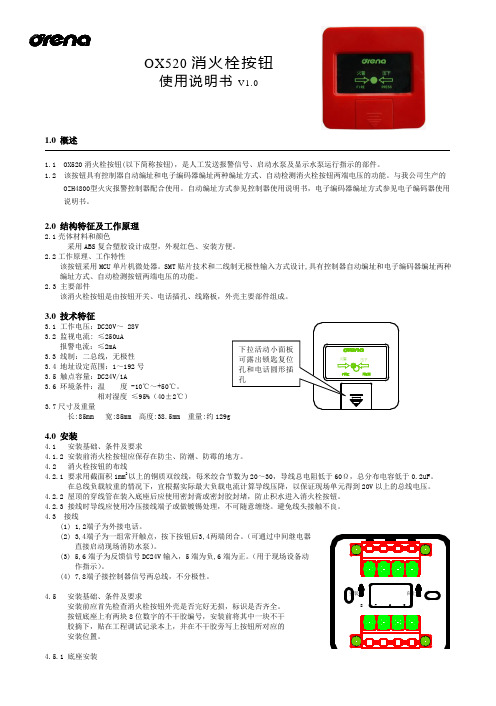
OX520消火栓按钮使用说明书V1.01.0 概述1.1 OX520消火栓按钮(以下简称按钮),是人工发送报警信号、启动水泵及显示水泵运行指示的部件。
1.2 该按钮具有控制器自动编址和电子编码器编址两种编址方式、自动检测消火栓按钮两端电压的功能。
与我公司生产的OZH4800型火灾报警控制器配合使用。
自动编址方式参见控制器使用说明书,电子编码器编址方式参见电子编码器使用说明书。
2.0 结构特征及工作原理2.1壳体材料和颜色采用ABS 复合塑胶设计成型,外观红色、安装方便。
2.2工作原理、工作特性该按钮采用MCU 单片机微处器。
SMT 贴片技术和二线制无极性输入方式设计,具有控制器自动编址和电子编码器编址两种编址方式、自动检测按钮两端电压的功能。
2.3 主要部件该消火栓按钮是由按钮开关、电话插孔、线路板,外壳主要部件组成。
3.0 技术特征3.1 工作电压:DC20V ~ 28V3.2 监视电流: ≤250uA报警电流:≤2mA3.3 线制:二总线,无极性3.4 地址设定范围:1~192号3.5 触点容量:DC24V/1A3.6 环境条件:温 度 -10℃~+50℃。
相对湿度 ≤95%(40±2℃)3.7尺寸及重量长:85mm 宽:85mm 高度:38.5mm 重量:约129g4.0 安装4.1 安装基础、条件及要求4.1.2 安装前消火栓按钮应保存在防尘、防潮、防霉的地方。
4.2 消火栓按钮的布线4.2.1 要求用截面积1mm 2以上的铜质双绞线,每米绞合节数为20~30,导线总电阻低于60Ω,总分布电容低于0.2uF 。
在总线负载较重的情况下,宜根据实际最大负载电流计算导线压降,以保证现场单元得到20V 以上的总线电压。
4.2.2 屋顶的穿线管在装入底座后应使用密封膏或密封胶封堵,防止积水进入消火栓按钮。
4.2.3 接线时导线应使用冷压接线端子或做镀锡处理,不可随意缠绕。
避免线头接触不良。
Uracron CY134 E-70产品数据表说明书

Page 1 of 1Product Data Sheet Uracron CY134 E-70The user is held to check the quality, safety and other properties of the product referred to herein. The information andrecommendations in this document are to the best of our knowledge, reliable. However, no rights whatsoever can be derived from this document or the information contained therein by any party, other than those expressly accepted by Synres in abinding sale and purchase agreement for product referred to herein. For the avoidance of doubt SYNRES MAKES NO WARRANTY OF ANY KIND, EXPRESS OR IMPLIED, INCLUDING THOSE OF MERCHANTABILITY AND FITNESS FOR PURPOSE. Unless explicitly agreed to otherwise in writing by Synres, all offers, quotations, sales and deliveries of Synres products are subject to its General Conditions of Sale ()D a t e o f i s s u e : S e p t e m b e r 2016, V e r s i o n : 1.0High solid hydroxy acrylic resin for two component coatingsApplications- car refinish enamels- solid color/clear top coat - general industrial coatingsPrincipal properties - weathering resistance - good chemical resistance - good petrol resistanceDilutability Xylene complete Solvent naphtha 100 complete Ethylacetate complete n-Butyl acetate complete 1-Methoxy 2-propyl acetate complete Methyl ethyl ketone complete Ethoxy propylacetate complete Propylacetate complete MAK complete MIAK complete MIBK completeCompatibilityUracron CY430, CY472, CY499 complete Uralac SY941, SY946 1) completeDesmodur N3390, N3600 2)completeDesmodur XP 2410 2)completeTolonate HDT LV, HDT LV2 3)complete Tolonate HDT 90 3) complete 1)DSM 2)Covestro 3)VencorexDelivery form:70% in butyl acetateProperty Range Unit TMViscosity, 23°C, ISO 3219 4.0 - 6.0 Pa.s 2013 Color, APHA 0 - 100 - 2017 Solids content 69 - 71 % 2022 Appearance clear - 2265 Acid value, on solid 0 - 10 mg KOH/g 2401Property Value UnitTMDensity, 23°C ca. 1020 kg/m³ 2160 Flash point ca. 25 °C 2800 Hydroxyl content ca. 3.4 % 2432Storage guidelinesThe resin should be stored indoors in the original, unopened and undamaged containers in a dry place at storage temperatures between 5°C and 30°C. Exposure to direct sunlight should be avoided.Shelf lifeUnder the stipulated storage conditions, the anticipated shelf-life is 360 days from last quality control date, as stated in the Certificate of Analysis.Material safetyA material safety data sheet of the products is available on request.Test methodsTest methods (TM) referred to in the tables are available on request.Starting formulations are available on request。
奥瑞那集团光子技术有限公司OLK3900G多线联动控制盘使用说明书
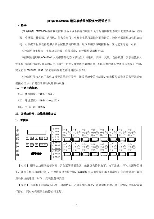
JB-QG-OLK3900G 消防联动控制设备使用说明书一、特点:JB-QG(QT)-OLK3900G消防联动控制设备(以下简称控制柜)是专为消防控制系统中的重要设备:消防泵、喷淋泵、排烟机、送风机、防火卷帘门、电梯等实施可靠控制而设计的。
控制柜采用模块化组合结构,可根据工程中设备的多少灵活配置模块的数量,组成专用多线制控制柜,应用起来方便、可靠。
本控制柜由主模块,主模块显示板,启停模块,启停模块显示板组成。
本控制柜能够和OZH4800A火灾报警控制器(联动型)相通讯,启动、反馈、设备数量、安装位置在火灾报警控制器上清楚、直观的显示,同时不受火灾报警控制器的限制,可以单独对现场设备实施可靠的控制,完全符合GB16806-1997《消防联动控制设备通用技术条件》。
本控制柜可与其它厂家火灾报警系统进行联网,接收系统中的控制器、输出模块等设备的常开无源输出接点信号,实现自动启动现场联动设备。
二、主要技术指标:(1)、环境温度:-10℃~+50℃(2)、环境湿度:≤95%(40±2℃)(3)、主电源:DC24V三、各模块外形、功能及操作方法【启动】用于启动现场的喷淋泵、消防泵等重要设备,在键盘允许状态下,按下此键,可启动现场的设备,并点亮相应启动指示灯,主模块发出火警声响,OZH4800火灾报警控制器(联动型)在启动菜单中显示启动模块的地址、时间、安装位置和类型。
【停止】当现场的联动设备已处于启动状态,若现场情况有变,需紧急停止时,按下此键,现场设备运行停止,同时点亮模块上的停止指示灯。
【反馈】无源常开动作信号回答。
当主模块接收到现场设备启动后的无源反馈信号后,反馈指示灯点亮,主模块发出火警声响,OZH4800火灾报警控制器(联动型)在反馈菜单中显示启动模块的地址、时间、安装位置和类型。
【线路故障】当主模块和现场连接的设备出现短路或断线时,此指示灯点亮,同时主模块发出故障声响。
【总启动】控制柜只要有一个设备在启动,点亮此总指示灯。
奥瑞那集团产品说明书

目录一、OZH280火灾报警控制器容量、配置、线制及设置 (1)二、OZH280火灾报警控制器操作方法 (3)三、附A: OZH280火灾报警控制器字符区位码对照表 (14)四、附B: OZH280火灾报警控制器汉字区位码对照表 (15)OZH280火灾报警控制器容量、配置、线制及设置一、主要技术指标1、交流输入电压:220V±10%, 50Hz±1%。
2、备用电源:24V 4Ah, 全密封免维护蓄电池。
3、使用环境:温度:0℃~+50℃;相对湿度:≤95% ( 40℃±2℃)。
4、容量:共2回路总线,每回路总线带192地址,整机最大容量为384个地址点。
1回路地址范围1~192;2回路地址范围201~392。
二、配置该设备由主机、电源和多线联动控制部分组成。
1、主机部分:(1)主机面板:液晶屏,键盘,指示灯,扬声器等。
(2)主机主板:(主机板包括回路部分)。
(3)主机电源:(电源板)。
三、线制(1)报警单元:两总线(无极性)(2)接口模块:四总线,两根信号线(无极性),两根电源线(24V,0V)。
(3)复示盘:四总线,两根信号线(无极性),两根电源线(24V,0V)。
(4)线制要求:a. 信号二总线(无极性),采用RVS双绞线,截面积≥1.0mm2。
根据工程具体情况配置。
b. DC24V输出线采用BV线,截面积≥2.5mm2。
c.信号二总线的主干线≥1.5mm2d. 控制器每路总线的往返电阻<20Ω.四、设置(1)系统刷新:首次使用应进行刷新操作,将以前的信息、记录、安装位置、联动编程、综合编程等全部清除;然后再进行登记操作、安装位置编程、联动编程、综合编程、多线联动设置等操作。
操作密码为:11111111。
(2)登记操作:首次加电或总线上部件变更时,需进行登记操作。
登记过程是自动完成的。
登记是按回路号进行的,登记后显示总数信息。
操作密码为:44441111。
Arzerra (ofatumumab) 产品说明书

Arzerra® (ofatumumab)(Intravenous)Document Number: IC‐0208 Last Review Date: 04/04/2022Date of Origin: 08/26/2014Dates Reviewed: 03/2015, 05/2015, 08/2015, 11/2015, 02/2016, 05/2016, 08/2016, 11/2016, 02/2017,05/2017, 08/2017, 11/2017, 02/2018, 05/2018, 04/2019, 04/2020, 04/2021, 04/2022I.Length of Authorization 1,10Coverage will be provided for 6 months with renewal subject to the following:∙CLL/SLL (first-line) may be renewed to allow for a total of 12 cycles∙CLL/SLL (relapsed) may not be renewed (unless the provisions for extended treatment have been met)∙CLL/SLL (single agent subsequent therapy) may not be renewed (unless the provisions for extended treatment have been met)∙CLL/SLL (extended treatment) may be renewed to provide for a total of 2 years of therapy ∙Waldenström’s Macroglobulinemia/Lymphoplasmacytic lymphoma may be renewed to allow for up to a total of 3 cyclesII.Dosing LimitsA.Quantity Limit (max daily dose) [NDC Unit]:∙Arzerra 100 mg/5 mL single-use vial: 3 vials Day 1∙Arzerra 1000 mg/50 mL single-use vial: 2 vials weekly x 7 doses, then 2 vials every 4 weeks, then 1 vial every 8 weeks for up to 24 monthsB.Max Units (per dose and over time) [HCPCS Unit]:CLL/SLL First‐Line▪30 billable units on day 1 and 100 billable units on day 8; then▪100 billable units every 28 days for up to 11 dosesSingle agent subsequent therapy▪30 billable units on day 1; then▪200 billable units weekly x 7 doses; then▪200 billable units every 28 days x 4 dosesRelapsed▪30 billable units on day 1 and 100 billable units on day 8; then▪100 billable units every 28 days for up to 5 dosesExtended Treatment▪30 billable units on day 1 and 100 billable units on day 8; then▪100 billable units 7 weeks later and every 8 weeks thereafterWaldenström’s Macroglobulinemia / Lymphoplasmacytic Lymphoma ▪30 billable units on day 1; then▪200 billable units every 7 days x 4 dosesIII.Initial Approval Criteria 1Coverage is provided in the following conditions:∙Patient is at least 18 years of age; ANDUniversal Criteria 1∙Patient has been screened for the presence of hepatitis B (HBV) infection (i.e., HBsAg and anti-HBc) prior to initiating therapy and patients with evidence of current or prior HBVinfection will be monitored for HBV reactivation during treatment; AND∙Must not be administered concurrently with live vaccines; ANDChronic Lymphocytic Leukemia (CLL)/Small Lymphocytic Lymphoma (SLL) † Ф1-3∙Used as first-line therapy; ANDo Used in combination with chlorambucil in patients considered inappropriate for fludarabine-based therapy (Note: only applies to CLL);ORo Used in combination with bendamustine ‡; AND▪Patient does not have del(17p)/TP53 mutation (patients ≥ 65 years, or younger patients with or without significant comorbidities; excluding use in frail patients[i.e., creatine clearance (CrCl) <70 mL/min]); OR∙Used as subsequent therapy; ANDo Used as a single agent; ORo Used in combination with fludarabine and cyclophosphamide (FC) for relapsed disease (Note: only applies to CLL);OR∙Used as extended treatment in patients with complete or partial response after at least 2 lines of therapy for recurrent or progressive disease (Note: only applies to CLL) Waldenström’s Macroglobulinemia/Lymphoplasmacytic Lymphoma ‡ 2,4∙Used as a single agent OR as part of combination therapy; AND∙Patient is intolerant to rituximab; ANDo Patient has previously failed primary therapy; ORo Patient has progressive or relapsed disease† FDA Approved Indication(s); ‡ Compendia Recommended Indication(s); Ф Orphan Drug IV.Renewal Criteria 1Coverage may be renewed based on the following criteria:∙Patient continues to meet universal and other indication-specific relevant criteria such as concomitant therapy requirements (not including prerequisite therapy), performancestatus, etc.identified in section III; AND∙Disease response with treatment as defined by stabilization of disease or decrease in size of tumor or tumor spread; AND∙Absence of unacceptable toxicity from the drug. Examples of unacceptable toxicity include: Hepatitis B virus reactivation/infection, progressive multifocal leukoencephalopathy, severe infusion reactions, tumor lysis syndrome, cytopenias (neutropenia, anemia, andthrombocytopenia), etc.V.Dosage/Administration 1,10CLL/SLL (First-line)Administer 300 mg on Day 1, then 1,000 mg on Day 8, followed by 1,000 mg on Day 1 of subsequent 28-day cycles for a minimum of 3 cycles until best response or amaximum of 12 cyclesCLL/SLL (Single agent subsequent therapy)Administer 300 mg on Day 1, followed 1 week later by 2,000 mg given weekly x 7 doses (infusions 2 through 8), followed 4 weeks later by 2,000 mg every 4 weeks for 4 doses (infusions 9 through 12) for a total of 12 dosesCLL/SLL (Relapsed) Administer 300 mg on Day 1, then 1,000 mg on Day 8, followed by 1,000 mg on Day 1 of subsequent 28-day cycles for a maximum of 6 cyclesCLL/SLL (Extended treatment)Administer 300 mg on Day 1, then 1,000 mg on Day 8, followed by 1,000 mg 7 weeks later and every 8 weeks thereafter for up to a maximum of 2 yearsWaldenström’s/ Lymphoplasmacytic lymphoma Cycle 1:∙Administer 300 mg on day 1, then 1,000 mg weekly for weeks 2 through 4; OR∙Administer 300 mg on day 1, then 2,000 mg weekly for weeks 2 through 5Cycle 2-3:∙Patients with stable disease or a minor response at week 16 of cycle 1 are eligible to receive a re-dosing cycle of 300 mg on day 1, then 2,000 mg for weeks 2 through5.Patients responding to cycle 1 or the redosing cycle who developed diseaseprogression within 36 months can receive treatment with 300 mg on day 1, then2,000 mg for weeks 2 through 5.VI.Billing Code/Availability InformationHCPCS Code:•J9302 – Injection, ofatumumab, 10 mg; 1 billable unit = 10 mgNDC:•Arzerra 1000 mg/50 mL single-use vial: 00078-0690-xx•Arzerra 100 mg/5 mL single-use vial: 00078-0669-xxVII.References1.Arzerra [package insert]. East Hanover, NJ; Novartis Pharmaceuticals Corporation, August2016. Accessed March 2022.2.Referenced with permission from the NCCN Drugs & Biologics Compendium (NCCNCompendium®) ofatumumab. National Comprehensive Cancer Network, 2022. The NCCNCompendium® is a derivative work of the NCCN Guidelines®. NATIONALCOMPREHENSIVE CANCER NETWORK®, NCCN®, and NCCN GUIDELINES® aretrademarks owned by the National Comprehensive Cancer Network, Inc. To view the mostrecent and complete version of the Compendium, go online to . Accessed March2022.3.Referenced with permission from the NCCN Drugs & Biologics Compendium (NCCNCompendium®) Chronic Lymphocytic Leukemia/Small Lymphocytic Lymphoma. Version2.2022. National Comprehensive Cancer Network, 2022. The NCCN Compendium® is aderivative work of the NCCN Guidelines®. NATIONAL COMPREHENSIVE CANCERNETWORK®, NCCN®, and NCCN GUIDELINES® are trademarks owned by the NationalComprehensive Cancer Network, Inc. To view the most recent and complete version of theCompendium, go online to . Accessed March 2022.4.Referenced with permission from the NCCN Drugs & Biologics Compendium (NCCNCompendium®) Waldenstrom’s Macroglobulinemia/Lymphoplasmacytic Lymphoma. Version2.2022. National Comprehensive Cancer Network, 2022. The NCCN Compendium® is aderivative work of the NCCN Guidelines®. NATIONAL COMPREHENSIVE CANCERNETWORK®, NCCN®, and NCCN GUIDELINES® are trademarks owned by the NationalComprehensive Cancer Network, Inc. To view the most recent and complete version of theCompendium, go online to . Accessed March 2022.5.Furman RR, Eradat H, DiRienzo CG, et al. A phase II trial of ofatumumab in subjects withWaldenstrom's macroglobulinemia. Blood. 2011;118:37016.Wierda WG, Kipps TJ, Mayer J, et al. Ofatumumab as single-agent CD20 immunotherapyin fludarabine-refractory chronic lymphocytic leukemia. J Clin Oncol 2010;28:1749-17557.Referenced with permission from the NCCN Drugs & Biologics Compendium (NCCNCompendium®) B-Cell Lymphomas. Version 1.2022. National Comprehensive CancerNetwork, 2022. The NCCN Compendium® is a derivative work of the NCCN Guidelines®.2NATIONAL COMPREHENSIVE CANCER NETWORK®, NCCN®, and NCCNGUIDELINES® are trademarks owned by the National Comprehensive Cancer Network,Inc. To view the most recent and complete version of the Compendium, go online to. Accessed March 2022.8.Rosenbaum CA, Jung SH, Pitcher B, et al. Phase 2 multicentre study of single-agentofatumumab in previously untreated follicular lymphoma: CALGB 50901 (Alliance). Br JHaematol. 2019 Feb 5.9.Van Imhoff GW, McMillan A, Matasar MJ et al. Ofatumumab Versus Rituximab SalvageChemoimmunotherapy in Relapsed or Refractory Diffuse Large B-Cell Lymphoma: TheORCHARRD Study. J Clin Oncol 2017;35 (5):544-551.10.Furman RR, Eradat HA, DiRienzo CG, et al. Once-weekly ofatumumab in untreated orrelapsed Waldenström's macroglobulinaemia: an open-label, single-arm, phase 2 study.Lancet Haematol. 2017 Jan;4(1):e24-e34. doi: 10.1016/S2352-3026(16)30166-1. Epub 2016Dec 1.11.Hillmen P, Robak T, Janssens A, et al. Chlorambucil plus ofatumumab versus chlorambucilalone in previously untreated patients with chronic lymphocytic leukaemia(COMPLEMENT 1): a randomised, multicentre, open-label phase 3 trial. Lancet. 2015 May 9;385(9980):1873-83. doi: 10.1016/S0140-6736(15)60027-7. Epub 2015 Apr 14.12.Robak T, Warzocha K, Govind Babu K, et al. Ofatumumab plus fludarabine andcyclophosphamide in relapsed chronic lymphocytic leukemia: results from theCOMPLEMENT 2 trial. Leuk Lymphoma. 2017 May;58(5):1084-1093. doi:10.1080/10428194.2016.1233536. Epub 2016 Oct 12.13.van Oers MH, Kuliczkowski K, Smolej L, et al. Ofatumumab maintenance versusobservation in relapsed chronic lymphocytic leukaemia (PROLONG): an open-label,multicentre, randomised phase 3 study. Lancet Oncol. 2015 Oct;16(13):1370-9. doi:10.1016/S1470-2045(15)00143-6. Epub 2015 Sep 13.14.Lemery SJ, Zhang J, Rothmann MD, et al. U.S. Food and Drug Administration Approval:Ofatumumab for the Treatment of Patients with Chronic Lymphocytic Leukemia Refractory to Fludarabine and Alemtuzumab. 10.1158/R-10-0570 Published September2010.15.Chen L, Shah R, Cwynarski K. et al. Ofatumumab is a feasible alternative anti-CD20therapy in patients intolerant of rituximab. Br J Haematol. 2019 Feb;184(3):462-465.doi: 10.1111/bjh.15110. Epub 2018 Jan 24.Appendix 1 – Covered Diagnosis Codes1010C83.00 Small cell B-cell lymphoma, unspecified siteC83.01 Small cell B-cell lymphoma, lymph nodes of head, face and neckC83.02 Small cell B-cell lymphoma, intrathoracic lymph nodes1010C83.03 Small cell B-cell lymphoma, intra-abdominal lymph nodesC83.04 Small cell B-cell lymphoma, lymph nodes of axilla and upper limbC83.05 Small cell B-cell lymphoma, lymph nodes of inguinal region and lower limbC83.06 Small cell B-cell lymphoma, intrapelvic lymph nodesC83.07 Small cell B-cell lymphoma, spleenC83.08 Small cell B-cell lymphoma, lymph nodes of multiple sitesC83.09 Small cell B-cell lymphoma, extranodal and solid organ sitesC88.0 Waldenström macroglobulinemiaC91.10 Chronic lymphocytic leukemia of B-cell type not having achieved remissionC91.12 Chronic lymphocytic leukemia of B-cell type in relapseAppendix 2 – Centers for Medicare and Medicaid Services (CMS)Medicare coverage for outpatient (Part B) drugs is outlined in the Medicare Benefit Policy Manual (Pub. 100-2), Chapter 15, §50 Drugs and Biologicals. In addition, National Coverage Determination (NCD), Local Coverage Determinations (LCDs), and Local Coverage Article (LCAs) may exist and compliance with these policies is required where applicable. They can be found at: https:///medicare-coverage-database/search.aspx. Additional indications may be covered at the discretion of the health plan.Medicare Part B Covered Diagnosis Codes (applicable to existing NCD/LCA/LCD): N/AJurisdiction Applicable State/US Territory ContractorE (1) CA, HI, NV, AS, GU, CNMI Noridian Healthcare Solutions, LLCF (2 & 3) AK, WA, OR, ID, ND, SD, MT, WY, UT, AZ Noridian Healthcare Solutions, LLC5 KS, NE, IA, MO Wisconsin Physicians Service Insurance Corp (WPS)6 MN, WI, IL National Government Services, Inc. (NGS)H (4 & 7) LA, AR, MS, TX, OK, CO, NM Novitas Solutions, Inc.8 MI, IN Wisconsin Physicians Service Insurance Corp (WPS) N (9) FL, PR, VI First Coast Service Options, Inc.J (10) TN, GA, AL Palmetto GBA, LLCM (11) NC, SC, WV, VA (excluding below) Palmetto GBA, LLCNovitas Solutions, Inc.L (12) DE, MD, PA, NJ, DC (includes Arlington &Fairfax counties and the city of Alexandria in VA)K (13 & 14) NY, CT, MA, RI, VT, ME, NH National Government Services, Inc. (NGS)15 KY, OH CGS Administrators, LLC。
奥瑞那集团光子技术有限公司ODM04气体灭火控制器使用说明书

JB-QB-ODM04 气体灭火控制器使用说明书深圳奥瑞那光子技术有限公司目录一、概述 (1)二、主要技术指标 (1)三、主要功能 (2)四、结构特点 (4)五、操作方法 (4)六、报警控制器的使用 (6)七、报警控制器的维护 (6)八、附录 (7)九、配套设备接线示意图 (9)十、接线端子示意图 (10)一、概述JB-QB-ODM04气体灭火控制器是依照国家标准GB16806-1997,GB4717和行业标准GA61-93,并结合实际应用,采用最新微电脑技术和抗干扰技术设计。
主要应用于CO2、EBM、FM200等气体灭火自动控制系统。
其设计合理,使用安全可靠。
气体灭火控制器具有自动、手动、紧急启动和紧急停止等工作方式,每区有二个火警检测回路,声光报警、延时喷放等控制输出。
在自动方式下,当防护区发生火灾时,报警控制器发出火灾报警信号指示该区火灾,并实现联动---经过30秒(0--60秒可调)疏散延时后,输出喷放控制信号,并接收反馈信号,指示喷放动作状态。
在手动方式下,火灾发生时,报警控制器只发出火灾报警信号不产生联动,由值班人员确认火警后,按下报警控制器上的紧急启动按键或现场的紧急启动按钮的面板玻璃,启动灭火系统。
在任何时候,按下报警控制器上的紧急启动按键或按下现场的紧急启动按钮的面板玻璃,将启动灭火系统。
在紧急启动或复合火灾报警后,喷放控制信号输出之前,按下报警控制器上的紧急停止按钮或按下现场的紧急停止按钮,系统将不会输出喷放信号。
当系统处于紧急停止状态时,可操作紧急启动按钮复位停止状态(由启动状态回到初始状态),复位后可重新启动系统。
气体灭火控制器可以与本公司生产的开关型离子感烟探测器、点型感温探测器、普通手动按钮,紧急启动停止按钮一起使用,组成火灾报警灭火控制系统。
用于各种工业或民用建筑的重要防火部门。
二、主要技术指标1、外形尺寸:400×120×600mm32、重量:15kg3、工作温度:10℃~50℃4、工作湿度:<95%(40℃)5、主电源:AC220V 50Hz6、备用电源:DC24V 7AH 铅酸蓄电池7、单一火警触点:每区一组(动作时继电器闭合,DC24V<1A)X6,X7,X8(X为区号A、B、C、D)。
ARTISAN技术集团-Alcatel-Lucent ADS 501产品说明书

ContentsADP/ADS User’s manualE d i t i o n 04 - M a y 98A - Introductions ADP/ADS Series One .............................................A 10s The various versions of ADP Series One ......................A 20s ADP/ADS Serie One Dry pumpsfor semi-conductor’s industry .......................................A 30s Types of monitoring systems ......................................A 40s Dry pump operational principle .................................A 50s The accessories .......................................................A 60sTechnical characteristics.............................................A 70B - Start-ups Safety instructions ....................................................B 00s Unpacking / Storage ...............................................B 10s Positioning the pump in pumping installation .................B 20s Installing anti-vibration pads........................................B 30s Modular version - Layout ..........................................B 40s Filling the pump oil housings ......................................B 50s Connection to the cooling circuit ...............................B 60s Inert gas purge connection (N 2 plug) ..........................B 70s Nitrogen purge flow sensor .......................................B 80s Connection to the pumping circuit .............................B 90s Electropneumatic exhaust valve connection (withdrawal) B 100s Pump power supply ...............................................B 110s Water flowrate and gas purge according to processes ...B 120s Checking the rotational direction ..............................B 130s Remote control plug connection (M3 monitoring) .........B 140s Remote control plug connection (M1 monitoring) .........B 141s RS 232 or RS 485 link wiring..................................B 150s Use of the Serial link (Service centers)........................B 160sInstallation of silencer heating kit...............................B 170E d i t i o n 04 - M a y 98E d i t i o n 04 - M a y 98ADP/ADS Series One dry pumpsDear Customer,you have just purchased an Alcatel dry pump. We thank you and are proud to include you in our customers.This product has benefited from Alcatel’s many years of experience in “semiconductor”processes and dry pumping. For optimum performance and to obtain full satisfaction from this equipment, we recommend that you study this manual before any intervention on your pump,in particular, the chapter on installation and start up.M ANUAL R EFERENCE:100 448E DITION:04 - May 1998A PPLICATIONS:• ALL “SEMICONDUCTORS” PROCESSESStripping, Etching, PECVD, LPCVD, MOCVD, Epitaxy, …• S CIENTIFIC RESEARCHA DV ANTAGES:Easily adaptable to processes - Tested design - Vertical pumping -Clean room compatible - Advanced monitoring system functions -Low noise level - Low operating cost - Easy maintenance and repairs - Anti-vibration frame - Compact.S PECIAL FEATURES:Multi-stage Roots technology - water-cooled multi-voltage motors -built-in monitoring system (remote optional) - anti-dust,sound-proof aesthetic covers, easily removed - incorporated purge line (N2) - Quick connection - Modular design and interchangeable parts - Easy to transport - Network compatible.E d i t i o n 03 - M a y 97A 10ADP/ADS Series OneMulti-stage pump withRoots technology Sealed motor with liquidcoolingGenuinely dry pumpVertical pumping ReliabilityEasy maintenance Pump designed for allprocesses2 versions- well-known technology - reliability- no fan (clean room compatible)- safe : no gas leak - quiet- multi-voltage, bi-frequency 50/60Hz- guaranteed by design - guaranteed by testingResidual gas spectrum free from hydrocarbon peaksMTBF > 50 000 hours - interchangeables parts - may be performed by user- Several equipments are available for semi-conductor’s applications, corrosives, CVD or clean processesStandard or modularE d i t i o n 03 - M a y 97E d i t i o n 03 - M a y 97A 20The various versions of ADP/ADS Series One• Footprint and volume minima • Total flexibility of use due to its modular possibilities of installation • No cover for easy integration• Guaranteed accessibility for preventive maintenance and repair.The “MD” Series is composed of a pumping unit on its frame and various modules :• Flowmeter panel (gas purgeand cooling water)• Utilities panel (gas purge and cooling connections)• Electrical box includingmonitoring (M1 or M3)• OEM interface panel /Remote controlBy design, these modules can be fitted to the pump frame in the best suitable position chosen by the user.Apart from its mounting in the different possible positions on the pump frame, the electrical box can be set remote to 5 meters from the pump if necessary.Modular VersionFor specific uses,Alcatel has developped a modular version fromthe series Onewhich offers in additionof standard versionthe following characteriticsE d i t i o n 04 - M a y 98E d i t i o n 04 - M a y 98E d i t i o n 04 - M a y 98E d i t i o n 04 - M a y 98directly be interfaced with most of the production equipments.E d i t i o n 03 - M a y 97E d i t i o n 03 - M a y 97E d i t i o n 03 - M a y 97E d i t i o n 04 - J a n u a r y 98E d i t i o n 04 - M a y 98E d i t i o n 04 - M a y 98E d i t i o n 04 - M a y 98E d i t i o n 03 - M a y 97Ed i t i o n 03 - M a y 97E d i t i o n 03 - M a y 97Ed i t i o n 03 - M a y 97E d i t i o n 03 - M a y 97Failure to remove the shipping braces could later cause the pump to seize as a result of a strain exertedE d i t i o n 03 - M a y 97E d i t i o n 03 - M a y 97E d i t i o n 03 - M a y 97E d i t i o n 04 - M a y 98E d i t i o n 04 - M a y 981 - Filling front Roots housing2 - Front Roots housing level sight glass 123654E d i t i o n 03 - M a y 97E d i t i o n 03 - M a y 97E d i t i o n 04 - M a y 98E d i t i o n 04 - M a y 98E d i t i o n 03 - M a y 97E d i t i o n 03 - M a y 97Connection to the pumping circuitFirst of all, remove the plug at the exhaust.For safety reasons, use at pump inlet as well as exhaust,accessories with materials and tightness compatible with pumped gases.For free exhaust tests (inert gas pumping), an anti-noise seal supplied with the pump can be fitted on to the silencer exhaust in order to reduce the exhaust noise level.In this case, do not fit the anti-noise seal.Make sure that the pressure at the exhaust does not exceed1200 mbar.At the exhaust pumpAnti-noise sealPreliminary precautionsE d i t i o n 03 - M a y 97Connection to the pumping circuitExhaust connectionDN40 ISO KF Pneurop.Several fitting accessories are available in Alcatel catalog.At inlet pumpInlet isolation valve(accessory)In order to prevent foreign bodies from entering the pump,leave the blank-off flange in place at the pump inlet and remove it at the time of use.(see section B 130).This accessory avoids a reverse flow of particles to the chamber when the pump is stopped.Connect the valve directly on the pump inlet flange using connecting accessories.Connect the valve to the chamber.Connect the electrical cable to the "inlet valve / exhaust valve"connector at the rear of the M3 monitoring system.E d i t i o n 04 - M a y 98E d i t i o n 04 - M a y 98Mains connectorE d i t i o n 04 - M a y 9817683245E d i t i o n 04 - M a y 98to main semiconductor processesStandard pump setting (no TC)E d i t i o n 04 - M a y 98E d i t i o n 03 - M a y 97When inspecting the direction of rotation of the Roots pump at installation, provide protection against the riskE d i t i o n 03 - M a y 97E d i t i o n 03 - M a y 97E d i t i o n 03 - M a y 97Remote control plug connection (M3 monitoring)Available outputs of Monitoring system M3State of «Emergency»Monitoring system M3Dry contacts : 250 V - 1 A - 100 V AThe front panel emergency stop button copy out contact is available between 1 and 2 contacts of “emergency“ plug at the rear of the monitoring system.E d i t i o n 03 - M a y 97(M1 monitoring)M1 Monitoring system M1 Remote monitoringRemote control«REMOTE»Controls (Input)Monitoring system M1Remote control function allows to :• Remote control of pumping functions “START/STOP/Emergency stop/PURGE”.•Copy out with dry contacts (250V - 1A - 100VA)the monitoring parameters. These contacts can be used to control automatisms.If the remote control is not used, put (REMOTE plug) the cover plug wired like :The remote control STOP button will stop the ADP , but it willrestart as the push button is released.Interrupteur MA/AR ON / OFF switchE d i t i o n 03 - M a y 97Available outputs ofMonitoring system M1Dry contacts : 250 V - 1 A - 100 V AThese contacts open in the presence of a fault.Two contacts available for each fault type.24VState of «Emergency»Monitoring system M1The front panel emergency stop button copy out contact is available between 7 and 8 contacts of “emergency“ plug at the rear of the monitoring system.。
jb-qb-ozh200火灾报警控制器使用说明书(v1.0)

目录第一章产品介绍 (2)概述 (2)主要技术指标 (2)产品功能特点 (2)第二章安装与接线............................................ 错误!未定义书签。
设备外观与机箱安装.. (3)部件组成 (3)电源连接 (3)端子说明 (4)第三章键盘及主界面说明...................................... 错误!未定义书签。
键盘说明. (4)主界面说明 (5)第四章菜单界面.............................................. 错误!未定义书签。
设置菜单. (5)操作菜单 (6)编程菜单 (6)查询菜单 (7)编码菜单 (7)帮助菜单 (7)第五章部件类型对照表........................................ 错误!未定义书签。
第六章常见故障排除方法...................................... 错误!未定义书签。
第七章联系方式.............................................. 错误!未定义书签。
附A字符区位码对照表......................................... 错误!未定义书签。
附B汉字区位码对照表 (9)第一章产品介绍1.1概述1.2 JB-QB-OZH200火灾报警控制器是由(ORENA)深圳市奥瑞那光子技术有限公司开发和生产。
它是一款消防报警系统的核心设备,具有将回路总线上各部件的火警信息以声、光形式反应出来,并完成一系列相关的必要功能。
1.3 JB-QB-OZH200火灾报警控制器的功能和特性完全符合《GB4717-2005火灾报警控制器》的要求。
本产品使用于各种小型工程,采用两总线分布智能数字信号传输技术,具有系统自诊断,回路器件自动识别等功能。
奥瑞那消防主机 6系列 说明书 图片版本

5.0 附 A:字符区位码对照表……………………………………………………(37)
6.0 附 B:汉字区位码对照表……………………………………………………(38)
火灾报警控制器(联动型) 使用说明书
1.0 概述 1.1 OZH4800 系列火灾报警控制器是消防报警及联动系统的核心设备,可采用手动/自动两种方式对现场设备进行联动控制。及时将
ZXn+ ZXn- 24V+ GND
(3) 24V 电压输出接线标示
24V 24V
GND GND
注:控制器由此端子输出 24V 电压,供其他设备使用
24V 24V
2
(4)多线输出接线标示
JQ1 JQ2 GND F1 F2 GND SWQ1
SWQ2
注:JQ1---------启动 JQ2---------停止 GND-------地 F1----------反馈 1 F2----------反馈 2 SWQ1-----自动启动 SWQ2-----自动停止
复 位 :退 出
a. 选择地址屏 蔽 :对部件(故障或无故障状态)进行的选择性隔离操作。若要对某一部件进行隔离,可用光标选择 此项,在选择地址隔离的画面中输入此部件的地址号:XX 机 XXX 路 XXX 号后按确认键即可。退出画面后部件被隔 离,并在 LCD 画面上显示屏蔽信息。隔离后的部件不会发出火警、故障及联动信号。
1.0 JB-QG(QT)-OZH4800 火灾报警控制器(联动型)……………………………………………………(1)
2.0 OTW6000 消防控制室图形显示装置……………………………………………………(22)
JB-QB-OZH200 火灾报警控制器使用说明书(V1.0)

目录第一章产品介绍 (2)1.1 概述 (2)1.2 主要技术指标 (2)1.3 产品功能特点 (2)第二章安装与接线 (3)2.1设备外观与机箱安装 (3)2.2 部件组成 (3)2.3 电源连接 (3)2.4 端子说明 (4)第三章键盘及主界面说明 (4)3.1 键盘说明 (4)3.2 主界面说明 (5)第四章菜单界面 (5)4.1 设置菜单 (5)4.2操作菜单 (6)4.3编程菜单 (6)4.4查询菜单 (7)4.5编码菜单 (7)4.6帮助菜单 (7)第五章部件类型对照表 (7)第六章常见故障排除方法 (7)第七章联系方式 (8)附A字符区位码对照表 (8)附B汉字区位码对照表 (9)第一章产品介绍1.1概述JB-QB-OZH200火灾报警控制器是由(ORENA)深圳市奥瑞那光子技术有限公司开发和生产。
它是一款消防报警系统的核心设备,具有将回路总线上各部件的火警信息以声、光形式反应出来,并完成一系列相关的必要功能。
JB-QB-OZH200火灾报警控制器的功能和特性完全符合《GB4717-2005火灾报警控制器》的要求。
本产品使用于各种小型工程,采用两总线分布智能数字信号传输技术,具有系统自诊断,回路器件自动识别等功能。
1.2主要技术指标交流输入电压187-242V AC/50Hz备用电源24V/2.2Ah 全密封免维护蓄电池静态电流≤130mA显示方式128*64点阵液晶屏显示使用环境温度:0℃~±50℃;相对湿度:≤95 ( 40℃±2℃)。
地址容量可选择配置16\32\64\100\150\192点结构型式壁挂式外型尺寸370*270*105设备容量≤192点线制:(1)报警单元:两总线(无极性)(2)声光单元:4线制,28v+,28v-和信号线ZX+、ZX-.(3)线制要求:a. 信号二总线(无极性),采用RVS双绞线,截面积≥1.0mm2。
根据工程具体情况配置。
奥瑞那电器火灾OZH6800-SS中文说明书
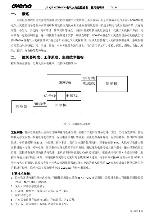
一、概述因供电线路或用电设备绝缘损坏引发的接地电气火灾的例子不胜枚举,为了有效减少电气火灾,OZH6800型电气火灾监控设备是我公司最新研制开发的面向民众和工业双重领域的新一代超早期电气火灾监控产品,具有高智能、小型化、多功能、高可靠性、简单实用等特点,该控制器采用模块化组板技术,优化了人机接口界面,同时具有一定的控制功能,这一切使整个系统易于安装、调试及维护。
OZH6800型电气火灾监控设备可配接我公司的OT6010型电气火灾探测器和其他任意厂家的电气火灾探测器,组成大容量电气火灾探测报警系统,系统报警后可联动气体钢瓶、阀、风机、卷帘、声光等报警和通风设备,可广泛用于工厂、学校、医院、商场、宾馆、剧院、展厅、办公楼等各种场合。
二、控制器构成、工作原理、主要技术指标控制器由主机板、电源及显示板组成,其构成框图如下:通讯线探测器显示板回路板电源线信号线电源线信号线主机板图一、控制器构成框图工作原理:电源电路主要由主供电电路和备电电路组成,主电工作的同时对备电进行充电,当电池充满时,自动转换为浮充状态,抵消电池的自放电,保证电池供电时的容量。
主机电路由单片机、程序存储器、接口扩展电路组成。
单片机采用78E516,功能强,指令丰富,是广为应用的优秀机种。
程序存储器64K。
人机对话电路主要由按键输入电路,时钟电路,显示驱动电路及数码管显示电路。
通过这些电路可输入操作指令,输出报警或指示信息。
监控设备采用模块化结构设计,主机板和回路板通过CAN总线通讯,壁挂式结构可接4个监控回路,监控回路最大可扩展至16路。
回路板和探测器之间采用两总线RS485通讯,每个回路可接63支我公司的OT6010型电气火灾探测器,组成大容量电气火灾探测报警系统。
接口电路的输入信号经AD转换后或数字解码后送入单片机进行处理,联动电路主要由驱动电路ULN2803和继电器组成。
主要技术指标:1、监控设备结构采用壁挂式机箱,可配接探测器容量为63×4=252支探测器,监控设备最大可配接探测器数量为63×16=1008支探测器。
奥瑞那4800智能说明书

(1)报警单元:两总线(ZX+、ZX-),无极性。
(2)接口模块:四总线,两根信号线(ZX+、ZX-),两根电源线(24V, 0V),信号线无极性。
(3)复示盘:四总线,两根信号线(ZX+、ZX-),两根电源线(24V,0V), 信号线无极性。
(4)线制要求: a. 信号二总线(ZX+、ZX-),采用 RVS 双绞线,截面积≥ 1.0mm2。根 据工程具体情况配置 b. DC24V 输出线采用 BV 线,截面积≥ 2.5mm2。 c、信号二总线的主干线≥ 1.5mm2 c. 控制器每路总线的往返电阻<20Ω.
OZH4800 火灾报警控制器(联动型)容量、配置、线制及设置
一、主要技术指标 1、交流输入电压:220V10, 50Hz1。 2、备用电源:24V 12Ah, 全密封免维护蓄电池; 3、使用环境:温度:0℃~+50℃; 相对湿度:≤ 95 ( 40℃±2℃)。 4、容量:基本配置可管理 4 路总线,每路总线带 192 地址,可扩展为 60
目录
一、OZH4800 火灾报警控制器(联动型)容量、配置、线制及设置…………(1) 二、OZH4800 火灾报警控制器(联动型)操作方法…………………………(3) 三、总线联动控制盘…………………………………………………………(24) 四、OZH4800 火灾报警控制器(联动型)汉字字符区位码对照表………(25)
路总线,整机最大容量为 11520 地址。 5、联动与报警统一编址,可根据实际要求设置。
二、配置 该设备由主机、分机和总线联动控制部分、多线联动控制部分组成,基本配
置为一台主机、一台分机、一块总线联动盘和一套多线联动控制盘。其中分机可 扩展到十五台,多线联动控制盘最大可容纳 127 个地址。
奥瑞那集团光子技术有限公司ODM04气体灭火控制器使用说明书
JB-QB-ODM04 气体灭火控制器使用说明书深圳奥瑞那光子技术有限公司目录一、概述 (1)二、主要技术指标 (1)三、主要功能 (2)四、结构特点 (4)五、操作方法 (4)六、报警控制器的使用 (6)七、报警控制器的维护 (6)八、附录 (7)九、配套设备接线示意图 (9)十、接线端子示意图 (10)一、概述JB-QB-ODM04气体灭火控制器是依照国家标准GB16806-1997,GB4717和行业标准GA61-93,并结合实际应用,采用最新微电脑技术和抗干扰技术设计。
主要应用于CO2、EBM、FM200等气体灭火自动控制系统。
其设计合理,使用安全可靠。
气体灭火控制器具有自动、手动、紧急启动和紧急停止等工作方式,每区有二个火警检测回路,声光报警、延时喷放等控制输出。
在自动方式下,当防护区发生火灾时,报警控制器发出火灾报警信号指示该区火灾,并实现联动---经过30秒(0--60秒可调)疏散延时后,输出喷放控制信号,并接收反馈信号,指示喷放动作状态。
在手动方式下,火灾发生时,报警控制器只发出火灾报警信号不产生联动,由值班人员确认火警后,按下报警控制器上的紧急启动按键或现场的紧急启动按钮的面板玻璃,启动灭火系统。
在任何时候,按下报警控制器上的紧急启动按键或按下现场的紧急启动按钮的面板玻璃,将启动灭火系统。
在紧急启动或复合火灾报警后,喷放控制信号输出之前,按下报警控制器上的紧急停止按钮或按下现场的紧急停止按钮,系统将不会输出喷放信号。
当系统处于紧急停止状态时,可操作紧急启动按钮复位停止状态(由启动状态回到初始状态),复位后可重新启动系统。
气体灭火控制器可以与本公司生产的开关型离子感烟探测器、点型感温探测器、普通手动按钮,紧急启动停止按钮一起使用,组成火灾报警灭火控制系统。
用于各种工业或民用建筑的重要防火部门。
二、主要技术指标1、外形尺寸:400×120×600mm32、重量:15kg3、工作温度:10℃~50℃4、工作湿度:<95%(40℃)5、主电源:AC220V 50Hz6、备用电源:DC24V 7AH 铅酸蓄电池7、单一火警触点:每区一组(动作时继电器闭合,DC24V<1A)X6,X7,X8(X为区号A、B、C、D)。
奥瑞纳消防使用说明书·
ORENA火灾报警及消防联动控制系统产品设计应用手册彩页:产品技术特点和优势控制器大容量,全系列控制器单机容量从64点、128点、192点、384点、768点、1536点、2304点……直至11520点,可多台控制器联网通讯,完全满足各种工程的需要,具有较高的性能价格比。
双向分布智能回路器件(探测器、模块、手报按钮)采用MCU微处理器,具有独立的智能分析和判断能力,内含智能软件,可根据现场环境的变化(温度、湿度、灰尘污染)自动调整报警阈值、滤除干扰,并与控制器双向传输信息,大大降低了误报率,加快了报警响应时间,最大限度地保证了报警的准确性。
真正的全总线系统结构系统内所有的各种探测器、模块、报警按钮、楼层火灾显示盘、回路扩展单元等外部设备全部挂接在总线上,不需额外的信号线。
系统结构简洁,节省大量线材和布线工时。
数字化信号传输二总线电流量脉宽数字化信号传输技术,通讯可靠,抗干扰性能强。
先进的自动编址功能无需人工设定地址,所有外部设备在线自动识别,自动编址,节省大量安装调试时间,提高了可靠性。
安装调试简便无极性两总线,避免了由于接线不当而引起的系统损坏。
可T形/环形任意布线,任意分支,节省大量线材和布线工时。
控制器上可显示回路器件的供电电压,方便系统调试。
大容量事件记录事件记录簿的容量为4096条,为用户日常使用管理和物业管理部门对使用情况的监督以及万一发生火灾后事故成因的分析都提供一个超长时间的可靠数据记录。
系统结构图前言奥瑞那公司成立于1995年,一直专业从事火灾自动报警设备的研发、生产、销售和服务。
200余名高素质员工、5000m2现代化厂房、众多自动化生产检测设备,严谨完善的质量管理体系,充分保证了产品的先进性和可靠性。
先进的技术和设备、严格的质量控制、优良的售后服务,是奥瑞那向客户提供可靠产品并让客户放心满意的有力保证。
奥瑞那的产品具有外形美观、质量可靠、服务优良的特点,主导产品火灾报警及消防联动控制系统已成功应用于数千项工程,在广东省消防指挥中心、广东省政协办公楼、甘肃省政府办公楼、江西省政协大厦、天健世纪花园、天然居(6栋32层住宅楼)、绿景蓝湾畔岛(8栋33层商住楼)、天鸿安柏丽晶、万科东海岸等许多重大工程中发挥着重要作用。
奥瑞那集团产品说明书

目录一、OZH280火灾报警控制器容量、配置、线制及设置 (1)二、OZH280火灾报警控制器操作方法 (3)三、附A: OZH280火灾报警控制器字符区位码对照表 (14)四、附B: OZH280火灾报警控制器汉字区位码对照表 (15)OZH280火灾报警控制器容量、配置、线制及设置一、主要技术指标1、交流输入电压:220V±10%, 50Hz±1%。
2、备用电源:24V 4Ah, 全密封免维护蓄电池。
3、使用环境:温度:0℃~+50℃;相对湿度:≤95% ( 40℃〒2℃)。
4、容量:共2回路总线,每回路总线带192地址,整机最大容量为384个地址点。
1回路地址范围1~192;2回路地址范围201~392。
二、配置该设备由主机、电源和多线联动控制部分组成。
1、主机部分:(1)主机面板:液晶屏,键盘,指示灯,扬声器等。
(2)主机主板:(主机板包括回路部分)。
(3)主机电源:(电源板)。
三、线制(1)报警单元:两总线(无极性)(2)接口模块:四总线,两根信号线(无极性),两根电源线(24V,0V)。
(3)复示盘:四总线,两根信号线(无极性),两根电源线(24V,0V)。
(4)线制要求:a. 信号二总线(无极性),采用RVS双绞线,截面积≥1.0mm2。
根据工程具体情况配置。
b. DC24V输出线采用BV线,截面积≥2.5mm2。
c.信号二总线的主干线≥1.5mm2d. 控制器每路总线的往返电阻<20Ω.四、设置(1)系统刷新:首次使用应进行刷新操作,将以前的信息、记录、安装位置、联动编程、综合编程等全部清除;然后再进行登记操作、安装位置编程、联动编程、综合编程、多线联动设置等操作。
操作密码为:11111111。
(2)登记操作:首次加电或总线上部件变更时,需进行登记操作。
登记过程是自动完成的。
登记是按回路号进行的,登记后显示总数信息。
操作密码为:44441111。
(3)主机板上8位拔码开关的设置1~4位:设置地址,固定为1。
- 1、下载文档前请自行甄别文档内容的完整性,平台不提供额外的编辑、内容补充、找答案等附加服务。
- 2、"仅部分预览"的文档,不可在线预览部分如存在完整性等问题,可反馈申请退款(可完整预览的文档不适用该条件!)。
- 3、如文档侵犯您的权益,请联系客服反馈,我们会尽快为您处理(人工客服工作时间:9:00-18:30)。
目录一、OZH280火灾报警控制器容量、配置、线制及设置 (1)二、OZH280火灾报警控制器操作方法 (3)三、附A: OZH280火灾报警控制器字符区位码对照表 (14)四、附B: OZH280火灾报警控制器汉字区位码对照表 (15)OZH280火灾报警控制器容量、配置、线制及设置一、主要技术指标1、交流输入电压:220V±10%, 50Hz±1%。
2、备用电源:24V 4Ah, 全密封免维护蓄电池。
3、使用环境:温度:0℃~+50℃;相对湿度:≤95% ( 40℃±2℃)。
4、容量:共2回路总线,每回路总线带192地址,整机最大容量为384个地址点。
1回路地址范围1~192;2回路地址范围201~392。
二、配置该设备由主机、电源和多线联动控制部分组成。
1、主机部分:(1)主机面板:液晶屏,键盘,指示灯,扬声器等。
(2)主机主板:(主机板包括回路部分)。
(3)主机电源:(电源板)。
三、线制(1)报警单元:两总线(无极性)(2)接口模块:四总线,两根信号线(无极性),两根电源线(24V,0V)。
(3)复示盘:四总线,两根信号线(无极性),两根电源线(24V,0V)。
(4)线制要求:a. 信号二总线(无极性),采用RVS双绞线,截面积≥1.0mm2。
根据工程具体情况配置。
b. DC24V输出线采用BV线,截面积≥2.5mm2。
c.信号二总线的主干线≥1.5mm2d. 控制器每路总线的往返电阻<20Ω.四、设置(1)系统刷新:首次使用应进行刷新操作,将以前的信息、记录、安装位置、联动编程、综合编程等全部清除;然后再进行登记操作、安装位置编程、联动编程、综合编程、多线联动设置等操作。
操作密码为:11111111。
(2)登记操作:首次加电或总线上部件变更时,需进行登记操作。
登记过程是自动完成的。
登记是按回路号进行的,登记后显示总数信息。
操作密码为:44441111。
(3)主机板上8位拔码开关的设置1~4位:设置地址,固定为1。
5位:键盘控制位,ON------锁键盘,OFF开键盘。
6位:ON 不检测电源;OFF检测电源。
7位、8位:未用五、引线标注1交流电源输入端子标示注: L :交流零线N :交流火线FG :地线2 24V 电压输出及回路总线接线端子标示注:ZX1+、 ZX2+: 回路1、2总线正极; ZX1、 ZX2-: 回路1、2总线负极;+24V 、GND :控制器由此端子输出24V 电压,供其他设备使用。
3 24V 电压输入接线标示注:控制器由此端子输入24V 电压,供回路巡检使用。
4 系统电源状态检测输入接线标示注:控制器由此端子输入主电、备电、充电等电源状态信号,供MCU 系统使用。
5 24V 电压输入接线标示注:控制器由此端子输入+5V 电压,供MCU 系统使用。
OZH280火灾报警控制器操作方法一、键盘说明主机面板上设有25只按键,其中数字键10只,功能键15只。
1、【消音】当有火警或故障时,扬声器发出火警或故障声,按下【消音】键,声音停止,同时点亮消音指示灯(黄色)。
2、【复位】键在菜单中,按下【复位】键,菜单向后退一级。
在厂标画面中,按下【复位】键,经确认后(按下【确认】键)执行复位操作。
3、【光标】【←】【→】用于移动光标或在综合界面中可切换当前显示项。
【↑】【↓】用于移动当前显示行。
4、【*】用于回路切换或编程组加1。
5、【#】用于回路切换或编程组减1。
6、【启动】【停止】用于启动、停止声光报警器。
7、【主菜单】用于进入主菜单画面。
8、【确认】用于执行所选功能。
9、【F2】用于自检操作,此功能是对控制器的所有发光二极管、声响器件,LCD显示器件进行检测。
10、【F1】----未用二、正常画面开机后,主机首先进行初始化,初始化完成后,自动进入厂标画面。
在此画面下,按【复位】键并确认后进行复位操作,按【主菜单】键进入主菜单画面。
三、异常画面异常画面中包括三个显示区,首火警区、声光报警器区、异常信息显示区。
当有异常情况发生都会出现如下画面,相应信息出现在相应的显示区内。
第一行:是首火警行。
“190”表示首火警的地址号是1回路190号。
表示此点是烟感,类型设置可在综合编程中修改;“2006/07/15 15:23”表示事件发生的日期和时间;第二行:是声光报警器行。
“208”表示声光报警器的地址号是2回路008号。
“2006/07/15 14:21”表示事件发生的日期和时间;“屏蔽”表示声光报警器的当前状态。
左边显示火警、屏蔽、监管、故障、启动、反馈的总数,右边显示信息的具体内容,显示格式是完全一样的,每类信息同时只显示一条。
通过*、#键可在这六项中切换当前显示的信息种类,通过上下键进行当前项内容的切换。
45秒无键盘输入时显示内容自动滚屏刷新。
显示内容的具体意义和首火警的说明是一样的。
四、主菜单注:打开键盘锁后,(使拨码第5位处于OFF位置)才能进行键盘操作。
按【主菜单】键进入主菜单。
主菜单主要包括八项一级菜单:信息查询、事件记录、通讯状态、系统设置、测试操作、启动操作、屏蔽操作、登记操作。
如下图所示,在此画面中可用光标键选择不同的功能项,按【确认】键执行相应的功能项。
除通讯状态和登记操作外其他每个菜单中又包含二级菜单。
通过上下光标键进行选择,按确认键即可进入相应功能菜单。
按复位键即可从下一级返回到上一级菜单。
(一)信息查询信息查询功能可查询火警、屏蔽、监管、故障、启动、反馈等异常信息(具体显示格式同异常画面);同时还可对部件信息和总线进行查询,其中部件信息查询包含三级菜单,可查询整机信息、各路信息、某路ID、某路电流、部件类型等信息。
(二)事件记录显示系统已经发生的火警、故障、启动、反馈、监管、操作、屏蔽和监管故障记录。
以上图火警记录为例,右上角为信息总页数和当前页数,每页4条记录。
每条记录所表示的意义如下:[001]15:28 奥瑞那公司生产部06年07月13日NO:001[001]探测器地址。
15:28火灾发生的时间。
06年07月13日火警发生的日期。
奥瑞那公司生产部报警部件安装位置描述,可在安装位置编程中修改。
表示火警触发部件的类型即感烟探测器。
类型设置可在综合编程中修改。
本系统用的部件类型共24种,可查阅部件信息中的部件类型。
NO:001 记录发生的顺序号。
(三)通讯状态(四)系统设置系统设置包括:时间设置、安装位置编程、联动与I、联动与II、多线联动设置、综合编程、联动或组、系统刷新八项功能。
1、时间设置:选择此菜单后按【确认】键,即可设置当前系统的日期和时间,完成设置后按【确认】键保存。
2、安装位置编程:描述部件具体的现场安装位置,用中文或数字表示,最多8个字。
具体内容是由实际安装位置决定,先输入部件的地址号,再采用区位码方式输入安装位置,编辑时,输入汉字或字母的区位码即可。
可查阅附表《区位码对照表》。
区码、位码都小于10时输入的是数字。
3、联动与I:如下图所示,联动与I共32组,每组输入条件1、条件2的表达式各为0~12个,每组输出模块数量为0~20个。
输入无误按【确认】键保存。
按#、*键可以切换浏览其他组的编程情况。
001~009:表示一回路的地址为1~9号的9个部件,205~213:表示二回路的地址为5~13号的9个部件,105~105:表示一回路的地址为105号的1个部件。
当条件1集合的任意一个或多个与条件2集合的任意一个或多个同时成立时,联动输出。
4、联动与II、联动或组:如下图所示,联动或组、联动与II共32组,每组输入条件的表达式各为0~12个,每组输出模块数量为0~30个。
输入无误按【确认】键保存。
按#、*键可以切换浏览其他组的编程情况。
001~009:表示一回路的地址为1~9号的9个部件,253~321:表示二回路的地址为53~121号的68个部件,105~105:表示一回路的地址为105号的1个部件。
当联动或组的联动条件集合的任意一个或多个成立时,联动输出。
当联动与II的联动条件集合的任意二个或多个成立时,联动输出。
5、多线联动设置:(待扩展)多线联动控制的设备类型在此界面进行编程,输入相应设备类型的代码即可;设备的安装位置在安装位置编程中进行,1~5号多线对应的安装位置编程地址为401~405号。
正确输入设备类型的代码后按【确认】键保存设置。
6、综合编程:当前行移到此行后按【确认】键,出现要求输入地址号界面,输入002号后再按【确认】键。
如下图第一行表示对1路123号编程。
类型:表示该点的属性。
此例001代表是烟感。
(具体某数所对应的是什么类型请见附表)。
安装位置:描述具体的现场安装位置,用八位汉字表示。
具体内容是由安装位置编程设定的。
显示盘:对于LED显示盘进行的编程,1201表示12号显示盘的01号灯。
对于LCD显示盘不需要编程。
注: A. 如连续编程,按【确认】键保存当前编程后地址号自动加1.B. 如果没有意外情况,类型和阈值一般不需要进行综合编程。
7.系统刷新:系统在初次使用时进行次操作,目的是清除FLASH内的所有记录、信息和各种编程信息,对存储器进行格式化,以便使用。
用光标选择相应的子菜单,按【确认】键进入要测试的画面,输入正确的测试部件地址号,按【确认】键即自动进行测试,并用曲线显示。
(六)启动操作用光标选择相应的子菜单,按【确认】键进入相应的子菜单的画面,输入正确的部件地址号,按【确认】键即自动进行启动/停止操作或进行模拟火警测试操作。
(七)屏蔽操作主要功能包括:当前故障屏蔽、选择地址屏蔽、解除所有屏蔽、选择地址解除四项操作。
1、当前故障屏蔽当某一或多个部件发生故障需隔离处理时,通过光标选择此项,按【确认】,待此项后出现“成功”时,故障隔离完成。
隔离后的部件不会再次发出火警、故障及联动信号。
2、选择地址屏蔽对某特定部件(故障或无故障状态)进行的选择性隔离操作。
若要对某一部件进行隔离,可用光标选择此项,按【确认】键进入子菜单,在选择地址隔离的画面中输入此部件的地址号XXX 号后按【确认】键即可。
退出画面后部件被隔离。
隔离后的部件不会发出火警、故障及联动信号。
3、解除所有屏蔽对当前所有隔离部件的一种解除操作,若要解除当前所有隔离,可通过光标选择此项,按【确认】键,待此项后出现“成功”字样时,当前所有被隔离部件被解除。
解除后的部件恢复到原有的状态。
4、选择地址解除对某特定隔离部件进行的选择性解除隔离操作。
若要对某一部件进行解除隔离,可用光标选择此项,在选择地址隔离的画面中输入此部件的地址号XXX号后按【确认】键,待此项后出现“成功”字样时,当前地址号部件被解除隔离。
解除后的部件恢复到原有的状态。
登记是在系统初始调试或系统内部位点有变化时需要进行的一种操作,它对系统内的部位点进行确认。