IC-CAP_教程
原创! ICCAP Wafer Mapping自动测试流程-essun

Revision: 1Page 1 of 321深圳深圳市市易商易商仪器仪器仪器有限有限有限公司公司ICCAP Wafer Mapping 自动自动测试操作测试操作测试操作流程流程Revision: 1Page 2 of 322REVREVISION DESCRIPTIONDATE.1.0 Initial release.07/10/2008 1.01 07/21/2013 Revision: 1Page 3 of 32目录目录标题 ........................................................................................................................................... 错误!未定义书签。
REVISION DESCRIPTION. (2)目录31概述 (4)1.1 范围41.2 目的41.3附件41.4参考文献42测试流程 (5)3具体测试步骤 (6)3.1使用GPIB线连接测试电脑、4156C与半自动探针台 (6)3.2将测试Wafer导入探针台并进行水平位置校准。
(7)3.3运行ICCAP2008并打开自动测试mdl文件 (8)3.4 初始化自动测试程序的General参数 (11)3.5 初始化自动测试程序的GPIB参数 (12)3.6 初始化自动测试程序的Thermo chuck参数 (14)3.7 初始化自动测试程序的Probe Station参数 (15)3.8 初始化自动测试程序的Switching Matrix参数 (21)3.9 初始化需要进行的Measure Setup Unit参数 (22)3.10 正式进行Wafer Test (31)3 Revision: 1Page 4 of 321 概述1.1 范围本文档详细描述了使用Agilent ICCAP软件和探针台12000/S300/E300/CM300自动完成Wafer Mapping 自动测试的详细流程。
VSC8221芯片评估板用户指南说明书

VSC8221User Guide VSC8221 Evaluation BoardContents1Revision History (1)1.1Revision 1.0 (1)2Introduction (2)3General Description (3)3.1Hardware Features (3)3.1.1Power Connections (3)3.1.2Copper Port RJ45 Connections (3)3.1.3SFP or SMA SGMII MAC Interface (3)3.1.4Switches (3)3.1.5Taitien 25 MHz Crystal (3)3.1.6External RefClk Option (4)3.1.7Silabs Microcontroller (4)3.1.8EEPROM Option (4)3.1.9CMODE Pins (4)3.1.10CLOCKOUT SMA (4)3.2Software Requirements (4)4Quick Start (5)4.1Board Configuration (5)4.1.1Clock and Reset (5)4.1.2Power Up (5)4.2GUI and Driver Installation (5)4.3Using the GUI (6)4.4Test Cases (7)4.4.1CAT5 to 802.3z Serdes with Clause 37 AutoNeg Detection (7)4.4.2CAT5 to SGMII with Modified Clause 37 AutoNeg Disabled (8)4.5Useful Registers (8)4.5.1Ethernet Packet Generator (8)4.5.2Far-End Loopback (8)4.5.3Near-End Loopback (8)5Additional Information (9)1Revision HistoryThe revision history describes the changes that were implemented in the document. The changes arelisted by revision, starting with the most current publication.1.1Revision 1.0Revision 1.0 was the first release of this document. It was published in December 2013.2IntroductionThe VSC8221 device is a low-power, Gigabit Ethernet transceiver suited for Ethernet Switches with SGMII/SerDes MAC interfaces, Media Converter applications, and SFP/GBIC modules. The VSC8221 device alsoincludes Vitesse’s VeriPHY Cable Diagnostics feature.This document describes the operation of the VSC8221 Evaluation Board (VSC8221EV). The Quick Startsection describes how to install and run the graphical user interface (GUI) to fully control the evaluationboard.Figure 1 • VSC8221EVThe following reference documents provide additional information about the operation of the VSC8221evaluation board.VSC8221 DatasheetVSC8221 Evaluation Board GUIVSC8221 Evaluation Board Schematics3General DescriptionThe VSC8221EV provides the user a way to evaluate the VSC8221 device in multiple configurations. OneRJ-45 connector is provided for the copper media interface. The MAC interface is provided via SMAconnectors or alternatively through an SFP connector.The VSC8221’s internal registers are accessed via the MDIO bus from an external microcontroller drivenby an external PC via USB. The accompanying GUI enables the user to read and write the deviceregisters. Alternatively, the VSC8211EV also has the capability to configure the VSC8221 through anEEPROM or Rabbit microcontroller (not-provided).The evaluation board has the option to use VSC8221’s internal on-chip oscillator by connecting a 25MHzcrystal to XTAL1 and XTAL2 or an external reference clock signal through the REFCLK SMA (J11).3.1Hardware Features3.1.1Power ConnectionsFor convenience, the evaluation board runs off a single +5VDC power supply. On board DC-DCconvertors create the +3.3VDC rail for the board and optional +1.2VDC rail. Power is supplied to theupper right corner of the board. Power can be applied either to the 5.5 x 2.1 mm barrel connector (J20)or the banana receptacles (J21 and J15). The slide switch (SW-4) selects between the external (on-board) and internal (on-chip) regulator option. J22 is an optional monitor point for the 1.2 V rail. Whenpowered by a bench top supply the board may draw up to 3 A maximum, module included.3.1.2Copper Port RJ45 ConnectionsThe RJ45 copper media PHY port (J1) uses a generic RJ45 jack with a discrete Pulse H5008 magnetictransformer.3.1.3SFP or SMA SGMII MAC InterfaceThe default MAC interface is provided through an SFP port connector. When using the SFP port, theSigDet polarity must be swapped in the VSC8221. See register 19E.0. Note that the transmit disablesignals (TXDIS) are connected to ground, thus the laser is always turned on.An optional MAC interface through SMA connectors may be enabled by removal and re-soldering the ACcoupling caps (C7–C10) from horizontal to vertical position.3.1.4SwitchesThere are two switches on the board:SW4 to select between utilizing a +1.2V internal regulator or external regulator. The default optionfor the board is to use the external regulator.SW2 allows the user to select the mode of the EECLK/PLLMODE pin. In the on position a logic highvoltage (pull-up resistor) configures the device for a 125MHz reference clock while a logic lowvoltage (pull-down resistor) selects a 25MHz reference clock option. This is a momentary ON switchwhich requires the user to hold it in the on position for 3 seconds during board power up or devicereset.3.1.5Taitien 25 MHz CrystalThe evaluation board is shipped configured to use the VSC8221’s internal on-chip oscillator. The jumperon J12 should be installed in the XTAL (left) position, and the jumper on J24 should be installed in thePLL enable or VCC (right) position.Note: Review the required action for SW2 mentioned above.1. 1.2.3.1.6External RefClk OptionThe user may choose to provide an external PHY REFCLK via the SMA connector (J11). The user must configure the device by installing a jumper on J24 in the PLL disable or ground (left) position and installing a jumper on J12 in the SMA (right) position.3.1.7Silabs MicrocontrollerA Silabs F340 microcontroller is included to facilitate a software interface to the registers on the VSC8221through a USB port.3.1.8EEPROM OptionThe user may choose to configure theVSC8221 via an EEPROM load. In order to program the EEPROM properly, pull-up or pull-down resistors must be configured for either R7 – R9 or R15 – R17. See Section 19 of the datasheet regarding to EEPROM programming requirement.3.1.9CMODE PinsOn the lower center of the board, there is an option to change the CMODE pin pull-up or pull-down resistors, R6, R12 – R14, and R18 – R21. See Section 18 of the datasheet for the detail on how toprogram the desired operating condition parameters through the CMODE configuration bits and how to choose the value of each CMODE pull-up or pull-down resistor.3.1.10CLOCKOUT SMAThe user should observe a 125MHz output clock through this SMA if the internal PHY PLL is operating properly.3.2Software RequirementsThe VSC8221 GUI can be loaded on to any PC or laptop that complies with the following requirements:The PC must run a recent version of MS-Windows. According to the Microsoft website, the following operating systems can run .NET based applications:Windows 2000Windows XP Windows Vista Windows-7Note: The GUI may be slower when run on Windows 2000 operating system.Hardware requirements must be considered when deploying/installing .NET applications. The minimum hardware requirement for a system running a .NET application is a Pentium 90MHz with 32 MB of RAM. For best performance, a newer system is recommended along with a minimum of 1 GB of RAM.If the .NET Framework 2.0 is not already installed, it may be obtained from the following link: /downloads/details.aspx?FamilyID=0856EACB-4362-4B0D-8EDD-AAB15C5E04F5&displaylang=en4Quick Start4.1Board ConfigurationPrior to powering the board, ensure that the jumpers and switches are in the following positions.Table 1 • Switch and Jumper ConfigurationSwitch/Jumper PositionJ19 (MDC)Jumper installed connecting F340 MDC to DUT MDCJ19 (MDIO)Jumper installed connecting F340 MDIO to DUT MDIOJ14 (TRSTB)Jumper installed connecting to GND. This is not requiredwhen R48 is installed.J12 (XTAL1/REFCLK)Jumper installed connecting center pin to XTAL.J24 (PLL ENABLE/DISABLE)Jumper installed connecting center pin to PLL ENABLE.SW2Hold in the left position during power-up and reset.SW4Slide to the left to use the on-chip regulator.4.1.1Clock and ResetPower must be applied and the clock (either 25 MHz or 125 MHz) must be active at the correctfrequency for the prescribed period of time in the datasheet before the RESETB pin is released.PLLMODE and OSCDISB pins are sampled during the device power-up or on assertion of RESETB pin.The board will be shipped configured for use of the 25 MHz crystal thus OSCDISB must be pulled up andPLLMODE must be pulled down during power-up or assertion of RESETB by setting J24 to the PLL enableposition and holding SW-2 in the 25 MHz position upon power-up.4.1.2Power UpProvide +5VDC to the board by plugging in the power cable (included in the kit) to J20. Two green LEDsshould illuminate: D12 on the left side of the board indicating +3.3VDC present and D11 on the right sideof the board indicating +1.2VDC present.4.2GUI and Driver InstallationDownload the VSC8221EV GUI from Vitesse’s website onto a PC that has a USB port. Install the GUI bylaunching the setup.exe file. Once installed, connect the USB cable between the USB port of the PC andthe USB connector (J16) on the evaluation board. Ensure the MDIO and MDC jumpers are properlyplaced from DUT to F340 on J23 to establish the connection between the VSC8221’s SMI pins and theSiLab F340.USB communication is assisted by the Silabs USBXpress® drive. If not present on the PC, the user willneed to download the USBXpress Development Kit from the Silicon Labs website (URL: http://www./products/mcu/Pages/USBXpress.aspx). Follow the installation directions after downloading the development kit.To ensure the USBXpress driver is installed and properly recognizing the evaluation board, go to ControlPanel and click on System>Hardware>Device Manager, and inspect the Universal Serial Bus controllerslisted to see if “USBXpress Device” appears. The following figure shows that the PC recognizes that aUSBXpress Device is connected.Figure 2 • USBXpress as Seen from the Device Manager Window4.3Using the GUILaunch the GUI either by clicking on the Desktop shortcut or clicking on the “Start – Programs – VitesseSemiconductor Corp - VSC8221_Evaluation_System” icons. The initial window will detect the attachedUSB devices automatically. The following figure shows a typical EVB Connection window.Figure 3 • Connection WindowThe EVB serial number should appear. If not, click on “Scan For USB Devices.” Select that EVB serialnumber then click “Launch GUI”. The Register List window will appear as shown in the following figure.1. a. b. c. d.Figure 4 • Register List WindowVerify that the device is up and running by reading MII Register 0. It should read back 0x1040. Reading back “0000” or “FFFF” (all 0’s or all 1’s) indicates a problem.To read or write the extended MII registers click on the ExtMII tab.An initialization script may be used to configure multiple VSC8221 registers. The initialization script is simply a text file which contains a list of registers to be written. Select the Device item on the top pull down menu area and click on Load-All-Registers option. A pop-up window will appear. Navigate to and select the desired script to be loaded.As per Section 31.1 of the datasheet, there are a number of internal registers that must be changed from their default value during device initialization. Use this method to initialize the device by loading “vsc8221_workaround31_1.txt” included in the GUI package under the Script/ directory. GUI Setup4.4Test Cases4.4.1CAT5 to 802.3z Serdes with Clause 37 AutoNeg DetectionAfter power-up or reset, the VSC8221 will operate at CAT5 to 802.3z Serdes with clause 37 Auto Negotiation Detection mode. An SFP loopback module enables MAC side SGMII loopback. 1G Ethernet received by the VSC8221 RJ-45 port is routed through the VSC8221 and looped back via SGMII through the SFP Electrical Loopback module.Set up the copper Ethernet traffic source (e.g., IXIA or Smartbits).Connect an Ethernet cable to an RJ-45.Plug in a SFP loopback module.Monitor the link-up bit in MII Register 1, bit 2 (MII 1.2), read twice to update. Traffic should now be flowing.1. 2. 3. 4. 5. 6. 4.4.2CAT5 to SGMII with Modified Clause 37 AutoNeg DisabledTo configure the device for Clause 37 Auto-negotiation disabled, perform these steps:Set up the copper Ethernet traffic source (e.g., IXIA or Smartbits).Connect an Ethernet cable to an RJ-45.Plug in a SFP loopback module.Write 0xBA20 to “MII Register” (Port 0) Reg 23 (Extended PHY Control #1).Write 0x9040 to “MII Register” (Port 0) Reg 0 (SW Reset for PHY Control setting to take effect).Monitor the link-up bit in MII Register 1, bit 2 (MII 1.2), read twice to update. Traffic should now be flowing.4.5Useful Registers4.5.1Ethernet Packet GeneratorExtMII 29E is the Ethernet Packet Generator register. Refer to datasheet for configuration options.A bad-CRC counter is in ExtMII 23.7:0. This counter will be saturate at 0xFF and is cleared when read.4.5.2Far-End LoopbackWhen MII Register 23 bit 3 is set to 1, it forces incoming data from a link partner on the media side to be retransmitted back to the link partner on the media interface.4.5.3Near-End LoopbackWhen MII Register 0 bit 14 is set to 1, the transmit data (TDP/TDN) on the MAC side is looped back onto the receive data (RDP/RDN pins) to the MAC.5Additional InformationFor any additional information or questions regarding the device(s) mentioned in this document, contactyour local sales representative.Microsemi HeadquartersOne Enterprise, Aliso Viejo,CA 92656 USAWithin the USA: +1 (800) 713-4113Outside the USA: +1 (949) 380-6100Sales: +1 (949) 380-6136Fax: +1 (949) 215-4996Email:***************************© 2013 Microsemi. All rights reserved. Microsemi and the Microsemi logo are trademarks of Microsemi Corporation. All other trademarks and service marks are the property of their respective owners.Microsemi makes no warranty, representation, or guarantee regarding the information contained herein or the suitability of its products and services for any particular purpose, nor does Microsemi assume any liability whatsoever arising out of the application or use of any product or circuit. The products sold hereunder and any other products sold by Microsemi have been subject to limited testing and should not be used in conjunction with mission-critical equipment or applications. Any performance specifications are believed to be reliable but are not verified, and Buyer must conduct and complete all performance and other testing of the products, alone and together with, or installed in, any end-products. Buyer shall not rely on any data and performance specifications or parameters provided by Microsemi. It is the Buyer's responsibility to independently determine suitability of any products and to test and verify the same. The information provided by Microsemi hereunder is provided "as is, where is" and with all faults, and the entire risk associated with such information is entirely with the Buyer. Microsemi does not grant, explicitly or implicitly, to any party any patent rights, licenses, or any other IP rights, whether with regard to such information itself or anything described by such information. Information provided in this document is proprietary to Microsemi, and Microsemi reserves the right to make any changes to the information in this document or to any products and services at any time without notice.Microsemi, a wholly owned subsidiary of Microchip Technology Inc. (Nasdaq: MCHP), offers a comprehensive portfolio of semiconductor and system solutions for aerospace & defense, communications, data center and industrial markets. Products include high-performance and radiation-hardened analog mixed-signal integrated circuits, FPGAs, SoCs and ASICs; power management products; timing and synchronization devices and precise time solutions, setting the world's standard for time; voice processing devices; RF solutions; discrete components; enterprise storage and communication solutions; security technologies and scalable anti-tamper products; Ethernet solutions; Power-over-Ethernet ICs and midspans; as well as custom design capabilities and services. Microsemi is headquartered in Aliso Viejo, California, and has approximately 4,800 employees globally. Learn more at www. .VPPD-03471。
MicroCap里面新建元器件模型
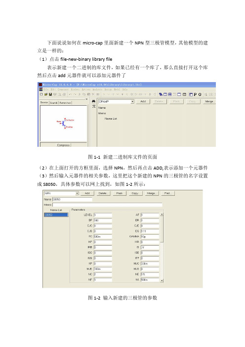
下面说说如何在micro-cap里面新建一个NPN型三极管模型,其他模型的建立是一样的:
(1)点击file-new-binary library file
表示新建一个二进制的库文件,如果已经有一个库了,那么直接打开这个库然后点击add元器件就可以添加元器件了
图1-1 新建二进制库文件的页面
(2)在上面打开的方框里面,选择NPN,然后再点击ADD,表示添加一个元器件(3)然后输入元器件的相关参数,这里把这个新建的NPN的三极管的名字设置成S8050,具体参数可以网上找到,如图1-2所示:
图1-2 输入新建的三极管的参数
(4)输入完参数之后,点击保存,那么这个库文件就保存了,注意记住保存的库文件名,比如是“jakill.lbr”之类的
(5)点击打开按钮,在文件选项中,选择lib类型的按钮,然后选择NOM.lib这个文件打开,在开头添加下面一句:
.lib”jakill.lbr”
表示自己新建的库可以在搜索元器件的时候被搜索到
(6)关闭库编辑界面,在左侧的元器件里面,选择NPN类型,然后在原理图界面里面放置,放置完之后,可以出现下面的界面。
图1-3放置完元器件之后出现的界面
(7)在Value一栏填写自己需要放置的元器件的符号,之前放置的符号应该是jakill或者是S8050, 天线完在右侧会出现这个NPN管子的型号,至此就ok了。
如图1-4所示。
图1-4 放置自己建立的NPN型三极管。
ads2005a快速入门中文教程

第一章:使用ADS项目当你生成、仿真及分析设计以达到你的设计目标时,ADS使用项目自动组织和存储数据。
一个项目包括电路原理图、布局图、仿真、分析和你创建的设计的输出信息,这些信息通过一些链接可以加到其他设计或项目中。
使用主窗口可以创建和打开项目。
当你运行ADS时这个窗口就会显示。
如下图:创建项目使用主窗口创建项目,然后你可以用来组织你的设计。
一个项目包括电路原理图、布局图、仿真、分析和你创建的设计的输出信息,这些信息通过一些链接可以加到其他设计或项目中。
创建一个项目包括以下几个步骤:打开项目一次只能打开一个项目。
当你开始打开一个项目,在当前打开的项目自动关闭前你会被提示去保存你对它所做的任何修改。
使用下面的方法可以打开一个项目:1. 选择File>Open Project,然后使用对话框定位并打开项目。
2. 使用主窗口上的File Browser栏定位项目并双击来打开它。
共享项目使用主窗口可以重新使用和共享项目而不需要手动包括所有组成项目的个体部分。
1. 添加链接来创建一个分级项目选择File>Include/Remove Projects,然后使用对话框定位并链接到这个项目。
2. 创建拷贝来复制一个项目选择File>Copy Project,然后使用对话框定位并拷贝这个项目。
3. 存档/不存档来转移一个简洁的项目存档文件选择File>Archive Project,然后利用对话框定位并存档项目。
第二章:使用ADS的设计ADS使用设计来存储你达到你设计目标而生成的原理图和布局图信息。
一个设计可以由单个的原理图或布局图组成,或者它可以由许多作为单个设计包含的内部子网络的原理图和布局图组成。
项目中的所有设计都可以直接从主窗口或从一个设计窗口内显示和打开。
在一个设计窗口中你可以:●创建和修改电路图和布局图●添加变量和方程●放置和修改元件、封装及仿真控制器●指定层及显示参数●使用文本和说明插入注释●由原理图生成布局图(及从布局图到原理图)创建一个设计和布局图的基本步骤如图所示:创建设计你可以使用下面两种方法之一创建一个新的设计(布局图):●选择主窗口上的Window>New Schematic或原理图(布局图)窗口上的File>New Design,然后使用对话框为你创建的文件命名。
mega使用教程
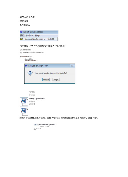
MEGA 的主界面:使用步骤1.序列导入可以通过Data 导入数据也可以通过file 导入数据。
妙Edit.TextRe启匚oovertAleFormattoMEGA.<. 昌Printer Setup …EaitMEGAAlti-X如果打开的文件是比对结果,选择Analyze ;如果打开的文件是序列文件,选择Align 。
広■訂飞testsequen 匚e.fasta1FASTAAleI 」572KBOpen&Filetest.s ■亡quence.fas FASFile572KBFSAFile5.72KE另外双击这些后缀名文件即可自动导入序列,导入后会弹出MEGA比对界面。
如果fasta序列导入报错,多是因为序列长度不同导致:fPTFTCN 黜aVLRLFPGERrHFTDEELWQYLSREVCSSPLPA5IIPEETJVCHMPWDLPS-NLEKEaYrFSTElEJiKYPWRTRSNRftlSSGYWKSLrGLEK^imSHGNQlVGL fbQLSLPPGFRnPTDEfLLVQYLCm^GYHrSL^IGDI&LYKr&FWDLPS^GTCFTin^GEYKCT-YLGKrt^rSEKEKyrFSPRDRKYPHGSRPHRVAGWW IkQ15IZETl3yRETFTE>EELm B Ef :LCR33iASHI?F5:LQLIA£:IDL¥KEI>E r WVi^5KaXFGEKEWYFi _£E !RB5i K¥F3G5S:PNHVAGSG¥HK5L HGTDKV]^TE :EREWZ A-PF-SraFHFrDEELILHYLI^t^SSSPVPLSIIftDVDIYKSDPWDLPAKAFrGEKEWYrFSPRD^PWGMPSrRAAASSYWKATSTDKLIAVPNGEGTHE^I百UFF 囲皿民卞亍诜丘1孙爬匸址m-Pt 即虑陀EFT 玳咗bPW 血塞自垃空已MFFM 亍匪站HPM 曲a 服迂弟品YIgm 』買茁二虽買IM 』玄品£MDBTJKLVKNGVIiRLPPGFRFHPTDEELWQYLKRKVCSSPLPASIIPEFDVCRAT-PtfDIxPGNLEKERYFFSTRE TDHIMEEYRLSSSPPSSMGPTQNWV1CRIFLKKRAGNKNDDODGESRNLRHJiNNNN D SDQIEIITT DQTDDKTK>AT4G274LQMGVREKDPLAQLSLPPGFRFYPTDEELLVQYLCRKVAGYHFSLQVIGDIDLYKFDPrJDLPSKQTCFTFVGEYNC GTKKA1VFYAGKAPKGTKTNWIMHEYRLIEHSRSHGSSRLDDWVLCRIYKRTSGSQFtQAVTPVQACREEHSTNGAPTNGLPSYGGYDAFRAAZGEAESGH^ZWRQQNS5GLTQSFGYSSSGFGV5G<JTETFRQ>AT3G1550QMGLQE.LDPLAQLSLPPGFREYPTDEELMVEYLCRKAAGHDFSLQLIAEIDLifKFDP»VLP£KALrGEKEWYFFSKTNWIMHE YRLIEPSRRNGSTKLDDWVLCRIYKKQTSAQKQAYNNLMTSGREYSi™STSSSSHQYDDVLESLELGLSRNVPSIRYGDGGT QQQTEGIPRFNNNSDVSftWQGFSVDPVNGFGYSGQQSS^FeFI如果序列长度不同,可以采用新建文件,将序列文件导入的方法 步骤:Align f Edit/BuildAlignment f createanewalignment f Data f open f RetrievesequencesfromFile将复制输入的序列另存输出看看 步骤:datafExportalignmentffastaformat■•■Fas-tapm 注■riTor^Ewpectedserjuenc -E-characleir,twt fou<id mSequencesaredIffereinilengihE.0**fihec5 EFVGIKK M TPOrarHFF DEELVLMT :5TEGQR¥C:|'—Irr ■TJ t.:iiZ3曰MAC-3|$-f*£3|kA A-criinH-fl,EepIcrKri'LJ::|WEditsearchgmffflfcWsbheflLienwilLP □匚r»阳触I*Q S Qp«nRacnpar9匚1口“PTylC甘BFMIK斷]MM^iiSE匚fed»Sfc-E®»rlAJ^nrw*e*rtD N*S HMJBW:* PjotewSe^jenceEi',lTranqlriBi/L-nlTAnilfliw■^vlmEOririhraLiTi^rT^lilri* JndrattlMi匚CIl'IjiJtaniSiiE■a R总昌国⑪甜段匙呈髙居屍〒$口>fiT5M37*»riL-q Ml.r'1t±iicii i i HniKD-ii>i I IHI ba■Qim■Lx■KiqQin r i'HMHad.Lki MI*I od I.uIDE SDLVIiFHPhe L FEMrt.¥CEKE?VF FSHRDRtf1FHCERFW%ft*CTn¥M^TGWH卩I GH Hl.I KI I1TH-E IRII YHInWlFII^M:!I FIHIIEF-H«LUUWWI H A:I VFIHHfa I IR KTIF~H4HI M~r I KViri DHWUC^EFKU[K.E.»fiLEIlFI«&TENFS5ECLLQKiAFUFqFQVI^SDFliD-^FOWF EQKP I■-liT^Ll^liiiHhrAiiij.tita NUiriLHLE屮I*HP!纯呂対II MSIJFLI I I WM^IMWLP&NHHEIHVl TU汕VMKiiT;I D*IASUTEIUH]>IUCLKKTLVFYKCHPPIHSiltTDtf[«HEWLSiSF H朋旬朋切沖4UDs.|tHLkl«Hiwi>^Ult I[I I Irk I IrWIHKll-1U卜摘IQ J I M-N,LLrS£D£LTSSilMfSiFA-■■-、口TM空片WHLUEEKSPLAHLELPPCF RFVPTBE[LLUqYLCRKIABYHFELqUJCO I DL Y轴hI引PL P5H L I l;lHi Wil^I'HPH.lYFHIi^UJ'rflCilAGkKYLMA IG K t>M]I mtUIHIII;jKHJI i>i¥HI;KHI'PStiCS^KLRDUULiCRIVKKirTCEiH lAUlTFVq^iCREEH5TH€S¥S5^SSqL D4ULKF PEI Hrn nMn<\iHEI Hrirt nr IHZI i'^vsiEWhAii IMAI EI AI^EIIUMH q^HNKCi ignisiwNs^u^fil3l;l^r.fllfeH[±QELbPI.A4L£LRf£FRFVPT@EfLHI£¥LCRHRACHDFSLQLJAE LDL^FbFWLPSHPmilEHl'BFRLARFinVLHAT l;T"HU I髯W CZIWUni KKII UIV I ILKAP Ifi H HIHUI HMI VRII B-Pkko FSA4k^!rM.MrS;£F£tfSwt£tmfX£HlQyhtOLESLHE EfeHft^LCFflRC^HALPHiAlignByMuscle AAA.AJ&AProteinSequencesMarlc/UnmarkSiteCtrl+M Specie a/Atibrv2+WP011931144.12+CAA44467H2氛A^N16207H1 4.WP_01229^898a AAAK1«222.1B Wr_D1203^132.1 7,KDP92253.1DeleteGap-OnlySites|A|A|AA|A|AAIVALAAA-LLL^VAI AjA|Aft|A|AA||__._.-|A|A|A|AA|AA||VV||V|A|L VL|L序列长度都被用横线补齐了2.池MHAlEgnmentExploreritesLsequEncz&fm硏DataEditSearch|AlignmentWebSequencerDi^pl^yHelpIV Signby匚tustalW选择muscle或者clustalw进行比对:clustalw—般用于DNA,muscle多用于蛋白。
capl调用c语言库函数
capl调用c语言库函数CapL(编译器应用域语言)是一种专门用于开发和测试汽车网络通讯协议的脚本语言。
虽然CapL本身具有强大的功能,但有时候我们可能需要调用C语言库函数来实现一些高级功能。
本文将详细介绍如何在CapL代码中调用C语言库函数。
第一步:了解C语言库函数的概念和作用C语言库函数是C语言提供的一系列函数,用于完成各种常见任务,如字符串操作、数学运算等。
这些函数通常以头文件的形式提供给开发者,并在编译时链接到应用程序中。
通过调用这些库函数,我们可以以更高效和可靠的方式实现复杂的功能。
第二步:选择适当的C语言库函数在使用C语言库函数之前,我们首先需要确定需要解决的问题,并选择适当的库函数。
这可以通过网络搜索、阅读文档或向开发社区寻求帮助来实现。
一旦我们选择了合适的库函数,我们就可以开始编写CapL代码来调用它们。
第三步:了解CapL中调用C语言库函数的语法在CapL中,调用C语言库函数的语法有一些不同于C语言的方式。
我们需要了解这些语法规则,以确保正确地调用库函数并处理返回值。
下面是一个简单的示例,展示了如何在CapL中调用C库函数:cdllFunction myFunction as void (arg1 as int, arg2 as int) ="my_library.dll"这段代码中,我们使用了“dllFunction”关键字来声明一个C库函数,并指定了函数名称、返回类型和参数类型。
在此之后,我们需要指定库函数所在的动态链接库(DLL)的路径和名称。
第四步:配置环境以支持C语言库函数调用为了支持C语言库函数的调用,我们需要在CapL的开发环境中进行一些配置。
这包括将C库函数的头文件和动态链接库包含到项目中,并设置正确的编译和链接选项。
如何进行这些配置将根据具体的开发环境而有所不同,我们需要根据实际情况进行调整。
第五步:调用C语言库函数并处理返回值一旦我们完成了环境配置,我们就可以在CapL中调用C语言库函数了。
Agilent IC-CAP 器件建模软件

IC-CAP 用户界面
IC-CAP用户界面能很容易地打 开或建立模型,设置用于测量的硬 件驱动程序,提取参数,仿真和优化 模型参数。图标、按钮和菜单条诸界 面项使 IC-CAP 进入对用户友好的 产品,它是类似最新 Windows 风格 的软件产品。
用户界面的基本工作有:
从 IC-CAP 主窗口点击各图标, 打开已有的模型文件,或建立新 的模型文件。
3
器件建模系统
用 Agilent 器件建模系统进行精 确测量
精确的器件模型始自精确和可 靠的测量系统。Agilent 针对应用的 建模系统对非线性器件测量提供了 独特的整体解决方案。我们不仅提 供标准建模系统,而且我们的大多 数建模系统都可以按您的特定要求 量身定制。
85225 系列高性能建模系统
应对挑战
这一最新版 IC-CAP 致力于应 对这些挑战,并为半导体公司带来 显著的竞争优势。
精确的 Agilent 专有模型和工业 标准模型
IC-CAP包括精确模型和先进的 统计分析,以建立和维护最新模型 库。您能在单一环境中用 IC-CAP 自 动化测量、仿真器件性能、提取数 据、优化模型参数、执行高级的统计 分析,以及产生最坏条件模型。ICCAP 为二极管、BJT、MOSFET、 MESFET、HEMT、噪声、热模型等 提供工业标准模型和Agilent专有模 型的提取例程。提取模块提供直流 至射频参数的全部提取能力。此外, IC-CAP还支持第三方开发的模型和 提取例程,其它各种仿真软件包,以 适应各种各样的客户要求。IC-CAP 还为工艺控制变量优化提供统计包, 它包括几种统计方法,以及用于实 际最坏条件分析的专有非参数边界 模型。
最灵活的软件环境
IC-CAP工作于开放和灵活的软 件环境。所有设置和宏均对用户全 面开放。您可使用参数提取语言建 造直接进入 IC-CAP 的自己模型或 提取方法。IC-CAP 开放接口允许您 使用用户 C 语言编写自己控制仪器 的测量驱动程序。IC-CAP 与我们的 建模系统一起,为今天的半导体行 业提供全面和集成的建模解决方案。
Agilent IC-CAP 器件建模软件

技术综述 全面、精确的参数提取和统计分析
IC-CAP 简介
IC-CAP(集成电路特性 和分析程序)是一种器件建模 软件,它为今天的半导体建模 提供强大的表征和分析能力。 IC-CAP 为器件设计师提供满 足各种建模需要的现代建模 工具,包括仪器控制、数据采 集、参数提取、图形分析、仿 真、优化和统计分析。所有这 些能力都组合在一个灵活、自 动和直观的软件环境中,以用 于有源器件和电路模型参数 的有效和精确提取。IC-CAP 为先进设计系统(ADS)或其 它商用仿真器提供建造模型 库的强大能力。
由于器件采用不同的制作工艺, 因此要求各种模型能迅速适应特定 的工艺流程。除了标准模型外,建模 软件还必须为建模工程师提供修改 和扩展模型参数的灵活性。为优化 模型和控制变量,器件设计师和工 艺师既需要精确模型,又需要统计 分析能力。而对于电路设计师来说, 需要用这两种工具确定正常性能和 极端(最坏条件)行为。
例子:用 IC-CAP Studio 开发的二极管模型提取例程。
用IC-CAP Studio 开发用户界面 是一项简单的任务。它不需要编程 语言。用户只需打开主窗中的 ICCAP Studio,整个开发就成为按钮 的点击。开发者能选择下拉菜单表 中的UI 项。把不同级的接口组织到 能彼此交互的分级层中。此外,分级 层还可调用可执行的传输和自动宏 命令,从而有可能由用户界面自动 执行整个测量至提取的过程。
选项允许您打开或关闭 GUI 页面,建立新 GUI 页面,或编 辑已有的 GUI 页面。
一旦建立了提取 UI,就可把它 保存在模型文件中,并与其他 ICCAP 用户共享。
GUI 项按层组织。顶层是父层,接 着是子层。您能从新 GUI 页面开 始,把父层和子层增加至 GUI 页 面,或改变已有的 GUI 项。
t113i的can口开发流程

T113I的CAN口开发流程一般包括以下步骤:
1. 初始化CAN套接字:首先,需要创建一个CAN套接字。
这可以通过调用socket函数,并指定PF_CAN和SOCK_RAW参数来完成。
2. 获取CAN设备索引:接下来,需要获取CAN设备的索引。
这可以通过调用ioctl函数,并使用SIOCGIFINDEX参数来完成。
3. 绑定CAN设备:使用bind函数将CAN套接字绑定到特定的CAN 设备上。
4. 配置CAN帧:在发送和接收数据时,需要使用can_frame结构体将数据封装成帧。
以上步骤完成后,就可以开始进行CAN通信了。
需要注意的是,具体的开发流程可能会因不同的硬件平台和操作系统而有所不同。
因此,在实际开发中,需要根据具体的硬件平台和操作系统进行适当的调整。
micro-cap中的声学器件使用技巧
micro-cap中的声学器件使用技巧声学器件是指用于声学信号传输、处理和转换的设备或元件。
在micro-cap中,声学器件的使用技巧可以帮助我们更好地设计和分析声学系统。
本文将从声学器件的选择、布局和参数设置等方面介绍一些使用技巧,希望能对读者在micro-cap中使用声学器件时有所帮助。
选择合适的声学器件是使用技巧的关键。
在micro-cap中,有许多不同类型的声学器件可供选择,例如麦克风、扬声器、声学滤波器等。
在选择声学器件时,我们需要考虑系统的需求和性能要求。
例如,如果需要采集声音信号,就需要选择合适的麦克风;如果需要放大声音信号,就需要选择合适的扬声器。
同时,还需要考虑声学器件的特性参数,如频率响应、灵敏度、功率等,以确保其满足系统设计的要求。
合理布局声学器件也是使用技巧的重要部分。
在声学系统设计中,声学器件的布局对信号传输和处理有着重要影响。
例如,在设计会议室的音响系统时,我们需要将扬声器布置在合适的位置,以确保声音能够均匀分布且不产生回声。
另外,麦克风的布置也需要注意避免噪声和干扰。
因此,在micro-cap中使用声学器件时,我们需要仔细考虑布局,确保声学信号能够得到有效传输和处理。
合理设置声学器件的参数也是使用技巧的关键。
在micro-cap中,我们可以通过调整声学器件的参数来优化系统的性能。
例如,对于声学滤波器,我们可以通过调整截止频率、增益和带宽等参数来实现滤波效果的优化。
另外,对于麦克风和扬声器等声学器件,我们也可以根据实际需求来设置其灵敏度、功率和阻抗等参数,以满足系统设计的要求。
除了以上提到的使用技巧,还有一些其他注意事项需要我们在micro-cap中使用声学器件时注意。
首先,我们需要确保声学器件的连接正确可靠,以避免信号传输中的失真和干扰。
其次,我们需要注意声学器件的保养和维护,定期清洁和检查器件的状态,以确保其正常工作。
另外,我们还需要注意声学器件的限制和安全性,避免超出其使用范围,造成损坏或危险。
Capture基础教程及CIS器件库

Capture基础教程及CIS器件库目录1Capture相关介绍 (3)1.1 Capture常用文档类型 (3)1.2 Capture软件包含的库 (3)2Capture设计流程: (3)2.1 Capture操作环境 (4)2.1.1 Capture有三个主要工作窗口: (4)2.1.2 Capture设计参数设置 (4)2.2 新建Project(create a design project) (6)2.3 绘制原理图 (8)2.3.1 原理图环境菜单 (8)2.3.2 Place part(放置器件) (10)2.3.3 放置电源和地(place power or GND) (11)2.3.4 连线及放置数据总线(Place wire or bus) (12)2.3.5 放置网络名称(place net name) (13)2.3.6 创建分级模块 (13)2.3.6.1 平坦式电路图 (14)2.3.6.2 层次电路图 (16)2.3.7 添加文字(place text) (18)2.4 原理图绘制后续处理 (19)2.4.1 DRC检测(Design Rules Check) (19)2.4.2 自动排序 (20)2.4.3 生成网络表 (21)2.4.4 生成材料清单 (22)3CIS器件库 (24)3.1 利用“公文包”文件夹实现EDA库的同步更新 (24)3.1.1 “公文包”概述 (24)3.1.2 利用“公文包”进行更新的优点 (25)3.1.3 如何建立“公文包” (25)3.1.4 “公文包”文件夹界面简述 (26)3.1.5 具体操作步骤:拷贝文件 (26)3.1.6 具体操作步骤:同步更新 (26)3.2 元器件库的搜索与浏览 (28)3.2.1 IPC_Viewer软件安装: (28)l首先安装微软的Netframework (28)l安装PCB Libraries LP Viewer (28)3.2.2 库的搜索与浏览 (28)3.2.3 申请建库 (30)3.3 Capture器件库的管理与调用 (30)3.3.1 使用Capture CIS的好处 (30)3.3.2 设置数据源 (30)3.3.3 Capture CIS的设置 (33)3.3.3.1 设置方法一:直接调用配置文件 (33)3.3.3.2 设置方法二:新建一个配置文件 (35)3.3.4 Footprint视图的设置 (45)3.4 带有数据库信息的器件清单的生成: (45)1Capture相关介绍1.1 Capture常用文档类型*.opj—项目管理文件*.dsn—电路图文件*.olb—图形符号库文件*.lib—仿真模型描述库文件*.dat—网络表文件*.bom—材料清单1.2 Capture软件包含的库•*.olb-Capture专用的图形符号库只有电气特性,没有仿真特性的库。
CAP协议

信令与协议分册目录目录第11章 CAP协议................................................................................................................11-111.1 概述...............................................................................................................................11-111.1.1 接口定义及功能..................................................................................................11-111.1.2 CAP协议的应用...................................................................................................11-111.1.3 协议栈结构..........................................................................................................11-211.1.4 消息结构.............................................................................................................11-211.2 CAP操作........................................................................................................................11-311.2.1 与呼叫相关的CAP操作.......................................................................................11-311.2.2 与短消息相关的CAP操作....................................................................................11-711.3 CAP基本信令流程..........................................................................................................11-8第11章 CAP协议11.1 概述11.1.1 接口定义及功能CAP(CAMEL Application Part,CAMEL应用部分)是从有线智能网的INAP协议演化而来,实现无线智能网功能实体gsmSSF、gsmSRF和gsmSCF之间的信令交互,从而实现对CAMEL业务的支持。
CAP方法软件安装

安装GMT
• 进入到文件夹 cd opt • 拷贝文件 su,然后输入超级用户密码 cp -r netcdf_4.3.1 /opt cp -r GMT_4.5.11 /opt chmod -R 755 /opt/netcdf_4.3.1 chmod -R 755 /opt/GMT_4.5.11 exit • 设置
安装pssac2
• 进入到pssac2文件夹 cd utils/pssac2 • 编译pssac2 chmod a+x pssac2 • 拷贝 cp pssc2 /home/xxx/bin
编译F-K
• 进入到FK安装程序文件夹 cd utils/fk3.1 • 编译 make • 拷贝 mkdir /home/xxx/bin cp fk syn trav /home/xxx/bin
编译CAP
• 进入到cap文件夹 cd cap • 编译 make • 拷贝 cp cap /home/xxx/bin
测试g77/f77编译器是否安装成功
• 执行命令f77,屏幕输出“没有输入文件”, 安装成功
三、专业软件安装
安装crust2.0
• 进入到crust2.0文件夹 cd utils/crust2.0 chmod a+x getCN2point cd
安装SAC
• 拷贝sac软件 su,输入超级用户密码 cp -r utils/sac /opt • 修改权限 chmod -R 755 /opt/sac • 退出超级用户 exit • 设置sac软件 vi .bashrc
CAP方法软件安装教程
韩立波 蒋长胜 郭祥云
中国地震局地球物理研究所,北京 100081 2015.04.13
一、FEDORA系统安装
元件布局(Component Placement)操作
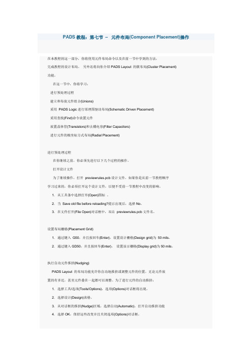
PADS教程:第七节–元件布局(Component Placement)操作在本教程的这一部分,你将使用元件布局命令以及在前一节中学到的方法,完成教程的设计布局。
另外还将向你介绍PADS Layout 的簇布局(Cluster Placement)功能。
在这一节中,你将学习:·进行预处理过程·建立和布放元件组合(Unions)·采用PADS Logic进行原理图驱动布局(Schematic Driven Placement)·采用查找(Find)命令放置元件·放置晶体管(Transistors)和去耦电容(Filter Capacitors)·进行元件的极坐标方式布局(Radial Placement)进行预处理过程在你继续之前,你必须先进行以下几个过程的操作。
打开设计文件为了继续操作,打开previewrules.pcb设计文件。
如果你是从前一节教程顺序学习过来的,你必须打开这个设计文件,以便不受前一节教程中改变的影响。
1. 从工具条中选择打开(Open)图标。
2. 当Save old file before reloading?提示出现后,选择No。
3. 在文件打开(File Open)对话框中,双击previewrules.pcb文件名。
设置布局栅格(Placement Grid)1. 通过键入G50,并且按回车(Enter),设置设计栅格(Design grid)为50 mils。
2. 通过键入GD50,并且按回车(Enter),设置显示栅格(Display grid)为50 mils。
执行自动元件推挤(Nudging)PADS Layout 的布局功能允许你自动地推挤或调整元件的位置,无论元件放置的有多近,甚至元件叠在一起都可以调整。
为了进行元件的自动推挤:1. 选择工具/选项(Tools/Options),选项(Options)对话框将出现。
模拟ic设计的基本流程
模拟ic设计的基本流程下载温馨提示:该文档是我店铺精心编制而成,希望大家下载以后,能够帮助大家解决实际的问题。
文档下载后可定制随意修改,请根据实际需要进行相应的调整和使用,谢谢!并且,本店铺为大家提供各种各样类型的实用资料,如教育随笔、日记赏析、句子摘抄、古诗大全、经典美文、话题作文、工作总结、词语解析、文案摘录、其他资料等等,如想了解不同资料格式和写法,敬请关注!Download tips: This document is carefully compiled by theeditor. I hope that after you download them,they can help yousolve practical problems. The document can be customized andmodified after downloading,please adjust and use it according toactual needs, thank you!In addition, our shop provides you with various types ofpractical materials,such as educational essays, diaryappreciation,sentence excerpts,ancient poems,classic articles,topic composition,work summary,word parsing,copy excerpts,other materials and so on,want to know different data formats andwriting methods,please pay attention!模拟 IC 设计的基本流程包括以下几个主要步骤:1. 系统规格定义确定模拟 IC 的功能和性能要求,例如输入输出范围、精度、带宽、功耗等。
ICCAP导入说明

一、单文本(TXT格式)的读取范例:读取如下txt文件数据并进行图形显示:注意:头三行为注释,共5列数据,每列针对一个VGS,每列的每个数据对应不同的VDS。
VGS从0.9V变化到3.3V,步进为600mV,共5个点;VDS从0,变化到15.3V,步进为150mV,共103个点。
显然,如上有两个扫描变量。
一个是VDS是主变量,一个是VGS是次变量。
于是,在ICCAP中设置步骤如下:1、新建一个DUT。
2、在Measure/Simulate中,设置Input,如上分析有两个变量,设置如下图,这步设置是为了程序编程和POLT显示做准备的。
VD的Sweep Order设为1,即主参数;VG的Sweep Order设为2,即次参数。
3、程序编写:先新建一个程序文件,如图:点击右边的Browse,会跳出如图的对话框,选PEL->Program即可。
确定则为如下:Execute是程序的执行按钮,而View则可看程序返回值。
代码如下:UPDATE_EXPLICIT! this PEL program reads data from a mdif formatted file! with the columnsLINPUT "enter path of file you want",mdiffile,mdiffileLINPUT "enter headline",head_line,head_linepath2setup="/read_mdif/mdif__3/read"sweep1 = USERC_num_of_points(1,path2setup)sweep2 = USERC_num_of_points(2,path2setup)!This is to define the correct data size for this Setup,!for later copy2paste Therefore, update the data sizeICCAP_FUNC("VD","Redisplay")COMPLEX tmp_ids[sweep1 * sweep2]r_stream = USERC_open(VAL$(mdiffile),"r")!skip the header linesi=0WHILE i < head_line ! replace by the number of lines to skip dummy = USERC_readstr(r_stream,0,"%*[^\n]%*1[\n]",string)i = i + 1END WHILEICCAP_FUNC("/","Status Window") ! brings status window to top leveli = 0WHILE i < sweep1k = 0WHILE k < sweep2tmp_ids[sweep1*k+i] = USERC_readnum(r_stream, 0, "%lf")PRINT "reading line ";sweep1*k+i;", i.e. ids = ";tmp_ids[sweep1*k+i]k = k + 1END WHILEi = i + 1END WHILEdummy = USERC_close(r_stream)!avoid unnecessary data behind this transformRETURN tmp_ids语句说明:1 LINPUT "enter path of file you want",mdiffile,mdiffile此语句是跳出对话框,要求需要加载数据的文件路径,把输入的路径值赋给mdiffile,而前一个mdiffile会记录这个路径,把它变为默认值,下次输入则不再需要重新输入路径了。
教学设备及学习用具类英语词汇

教学设备及学习用具教具teachi ng aid模型model图表chart表格form地图map挂图wall map课程表curric ulum schedu le时间表,进度表schedul e统计表diagra m字母表alphabet投影仪projector实物投影仪, 幻灯机epi diascope录音机record er磁带tape幻灯片sli de电脑comput er笔记本电脑 b ook-comput er黑板blackb oard讲台plat form讲桌teacher’s desk操作台ope ratin g platfo rm粉笔chalk彩色粉笔col ored chalk粉笔槽 a ledgefor chalkon a blackb oard黑板擦,橡皮eraser教鞭(teachi ng)pointe r地球仪globe卡片,抽认卡flashcard测试台test desk测试图resolu tion chart书桌desk椅子chair凳子,板凳stool升降书桌moveme nts desk算盘abacus计算器calcul ator活页夹loo se-leaf binder铅笔盒pencil-box文具盒pencil case文具statio nery直尺straig htedge比例尺archi tect’s scale计算尺sli de rule圆规compas ses三角板set square量角器protra ctor订书机staple r订书针staple卷笔刀pencil sharpe ner尺子ruler胶带adhesi ve tape书包school bag双肩背包backpa ck钢笔pen笔心refi ll笔帽the cap of a pen铅笔pencil中性笔neutra l pen圆珠笔ball pen毛笔brush自动笔pro pelli ng pencil采笔crayon光笔ligh t pen笔记本notebo ok活页笔记本l oose-l eaf notebo ok课本, 读本textbo ok初级读本pri mer参考书,工具书reference book参考书目bi bliog raphy参考资料refere n ce materi al字典,词典dictio nary简明词典co nveydi ctio nary双语词典bi lingual dictio nary袖珍词典po cket di ctio nary汉英词典Chi nese-Englis h dictio nary书book丛书 a series of books报纸newspa per杂志magazi ne档案file s(archiv e s)档案柜fil ing cabine t档案材料do ssier资料materi al第一手资料fi rsth and inform ation学习资料materi al for study调查资料fi nding s地图集atl as剪贴本scrap book课外读物bo oks for outsid e readin g百科全书en cyclo pedia不列颠百科全书Enci clopa ediaB ritan ni ca汉英对照读本Chinese-English biling ual text book 读书笔记readin g notes抄本tran scrip t标本speci men检字表index of Chines e charac ters教材teachingmateri al教程course分类卡片cl assified card空座位uno ccupi ed seat历史地图hi stori cal map笔帽the cap of a pen透明胶带scotchtape图解词典pi ctori al dictio nary图解法gra phicmethod硬纸板cardboard (hardbo ard)一付圆规apair of compasses阅读机rea der。
CAP教学课件ppt

cap在智能家居中的应用案例
例如,智能照明控制系统可以通过使用cap理论来实现数据的一致性 和可用性,保证不同设备之间传输的数据的准确性和可靠性。
THANKS
CAP系统中的敏感信息如果未得到妥善保护,可能会被 非法获取、泄露和滥用。
完整性破坏
攻击者可能通过网络诱骗、恶意代码或其他手段破坏 CAP系统的完整性,导致数据篡改或丢失。
cap加密方式
同态加密
同态加密能够在不暴露明文数据的情况下进行计算操作,保证计 算结果的准确性。
属性加密
属性加密基于数学难题,对数据属性进行加密,使得只有符合特 定条件的数据才能被解密。
早期指数
早期的指数包括道琼斯工业平均指数、标准普尔500指数等,这些指数为投资者提供了参 考依据。
CAP的推出
随着市场的发展,越来越多的指数开始推出,其中之一就是CAP,它于20世纪90年代推 出,并逐渐成为市场上重要的参考指标之一。
cap应用场景
投资策略
CAP作为一种股票指数,可以作为投资策略的参考指标之一 。投资者可以根据CAP的表现来决定自己的投资组合配置。
04
cap性能优化
cap性能评估指标
吞吐量
评估系统单位时间内处理请求的能 力,以TPS(每秒事务数)为衡量 指标。
并发量
评估系统在同一时间内处理多个请 求的能力,以QPS(每秒查询数) 为衡量指标。
响应时间
评估系统处理请求的延迟时间,以 毫秒为单位。
可扩展性
评估系统在增加或减少资源时,性 能的变化情况。
ICCAP导入说明

一、单文本(TXT格式)的读取范例:读取如下txt文件数据并进行图形显示:注意:头三行为注释,共5列数据,每列针对一个VGS,每列的每个数据对应不同的VDS。
VGS从0.9V变化到3.3V,步进为600mV,共5个点;VDS从0,变化到15.3V,步进为150mV,共103个点。
显然,如上有两个扫描变量。
一个是VDS是主变量,一个是VGS是次变量。
于是,在ICCAP中设置步骤如下:1、新建一个DUT。
2、在Measure/Simulate中,设置Input,如上分析有两个变量,设置如下图,这步设置是为了程序编程和POLT显示做准备的。
VD的Sweep Order设为1,即主参数;VG的Sweep Order设为2,即次参数。
3、程序编写:先新建一个程序文件,如图:点击右边的Browse,会跳出如图的对话框,选PEL->Program即可。
确定则为如下:Execute是程序的执行按钮,而View则可看程序返回值。
代码如下:UPDATE_EXPLICIT! this PEL program reads data from a mdif formatted file! with the columnsLINPUT "enter path of file you want",mdiffile,mdiffileLINPUT "enter headline",head_line,head_linepath2setup="/read_mdif/mdif__3/read"sweep1 = USERC_num_of_points(1,path2setup)sweep2 = USERC_num_of_points(2,path2setup)!This is to define the correct data size for this Setup,!for later copy2paste Therefore, update the data sizeICCAP_FUNC("VD","Redisplay")COMPLEX tmp_ids[sweep1 * sweep2]r_stream = USERC_open(VAL$(mdiffile),"r")!skip the header linesi=0WHILE i < head_line ! replace by the number of lines to skip dummy = USERC_readstr(r_stream,0,"%*[^\n]%*1[\n]",string)i = i + 1END WHILEICCAP_FUNC("/","Status Window") ! brings status window to top leveli = 0WHILE i < sweep1k = 0WHILE k < sweep2tmp_ids[sweep1*k+i] = USERC_readnum(r_stream, 0, "%lf")PRINT "reading line ";sweep1*k+i;", i.e. ids = ";tmp_ids[sweep1*k+i]k = k + 1END WHILEi = i + 1END WHILEdummy = USERC_close(r_stream)!avoid unnecessary data behind this transformRETURN tmp_ids语句说明:1 LINPUT "enter path of file you want",mdiffile,mdiffile此语句是跳出对话框,要求需要加载数据的文件路径,把输入的路径值赋给mdiffile,而前一个mdiffile会记录这个路径,把它变为默认值,下次输入则不再需要重新输入路径了。
- 1、下载文档前请自行甄别文档内容的完整性,平台不提供额外的编辑、内容补充、找答案等附加服务。
- 2、"仅部分预览"的文档,不可在线预览部分如存在完整性等问题,可反馈申请退款(可完整预览的文档不适用该条件!)。
- 3、如文档侵犯您的权益,请联系客服反馈,我们会尽快为您处理(人工客服工作时间:9:00-18:30)。
• Hands-on Tutorials
Group/Presentation Title Agilent Restricted Month ##, 200X
What is IC-CAP?
better match between measured and simulated data
Group/Presentation Title Agilent Restricted Month ##, 200X
Visualize the Modeling Process
step 1
Measure
–A netlist (parameter values) sent to simulator –Netlist syntax must agree with simulator –The simulator uses the model and the netlist to predict
the behavior of the device or circuit Model parameters also used in sensitivity analysis
–monitor process variation, etc.
NETLIST: R=1.27K
Simulator Model: R = V/I
Group/Presentation Title Agilent Restricted Month ##, 200X
What is IC-CAP Modeling ?
IC-CAP is the...
Integrated Circuit Characterization and Analysis Program
Group/Presentation Title Agilent Restricted Month ##, 200X
What can IC-CAP do?
Drive instruments to obtain measure data Simulate data: built-in or external simulators Automatically extract model parameters Allow creation of user-defined extractions Plot measured and simulated data Plot user-defined functions Optimize parameter values Provide Statistical Analysis and Database
Step 2: Extract Parameter Values
Use built-in extraction functions or d Write your own extraction programs
dt
Step 3: Simulate
Parameter List Inputs/Outputs Circuit
y
i
slope = 1/R
v
Most extractions come from fitted lines and intercepts.
Predicted or Simulated
Measurement Data Points
x
Group/Presentation Title Agilent Restricted Month ##, 200X
It is driving a measurement system and using the software:
STEP 1: select the model (equations) STEP 2: measure the device or circuit to obtain data STEP 3: extract the parameter values from measured data STEP 4: return the parameter values to model STEP 5: simulate the response using the model (netlist) STEP 6: compare simulated and measured data STEP 7: if desired, optimize (adjust) parameter values for a
Agenda
• Modeling and ICCAP Fundamentals • Measurements and Extractions • Simulation and Optimization • Introduction to PEL • Customizable Graphical User Interface • IC-CAP 2006: What’s New
Simulator
Group/Presentation Title Agilent Restricted Month ##, 200X
Group/Presentation Title Agilent Restricted Month ##, 200X
Direct Extraction vs. Optimization
Model parameters can be obtained by direct extraction or by optimizing parameters for least error between the model and data. Direct extraction involves an explicit equation for the parameter value and is efficient. Optimization involves iteration of successive parameter values until an error function is minimized. This process is less efficient. Often, direct extraction is used for subsets of parameters and optimization is used for best fit to data with the full parameter set. IC-CAP provides an efficient procedure for this combined process.
Group/Presentation Title Agilent Restricted Month ##, 200X
Fitting by Successive Approximation is an Iterative Process
Guess the ents A and B
Minimize the RMS error using an Optimization Process to obtain the best values of A and B
NETLIST
Simulator Spice MNS * other
* SABER, ELDO, HSPICE, SPECTRE, PSPICE ...
Group/Presentation Title Agilent Restricted Month ##, 200X
Group/Presentation Title Agilent Restricted Month ##, 200X
A Model is used to characterize a device or circuit: Basic types of models:
Physical: based on physics and processes * - ex: Shockley Empirical: based on equations - ex: Curtice3 Semi-empirical: based on equations and physics - ex: Gummel-Poon Table-based: based on measured data - ex: HP Root
Group/Presentation Title Agilent Restricted Month ##, 200X
Modeling and IC-CAP Fundamentals
Group/Presentation Title Agilent Restricted Month ##, 200X
What is a Model ?
Step 4: Optimize
Use the built-in Optimize function: Specify parameters to adjust and target The simulation adjusts parameters and repeats until target is reached.
Step 1: Measure
IC-CAP Software
Measurement Hardware
INPUT (stimulus) HP-IB Commands
OUTPUT (response) Measured Data
Device & Fixture or Probe Station
Group/Presentation Title Agilent Restricted Month ##, 200X
A mathematical description of the stimulus-response electrical behavior of a circuit or a device:
