最新综合版光幕新使用说明书
IDEC-DATASENSOR SG2系列安全光幕说明书
IDEC-DATASENSOR Safety Light CurtainsType 2 SG2 Series (Basic & Extended Models)Hand ProtectionPresence ProtectionIntegrated light curtain for Hand Protection or • Presence ControlOperating distance up to 19m• Controlled heights from 150 to 1800mm • Compact 32 x 37mm profile• Sturdy profile and rotating brackets• Test/Restart, Auto/Manual Restart, EDM, Anti-interference • User interface with display • Alignment function• The SG2 Type 2 series offers two models, the SG2 basic and the SG2 extended. Available functions include Test/Restart, EDM and Anti-interference. With very fast response times, the SG2 series can be installed right next to a hazardous area improving productivity. The ro-tating mounting brackets make installation and the alignment of the emitting and receiving units easy, even at long distances and in applica-tions that use mirrors.Type 4 SG4 SeriesFinger ProtectionHand ProtectionIntegrated light curtain for Finger Protection or • Hand ProtectionOperating distance up to 6m for Finger Protection series • & 19m for Hand Protection seriesControlled heights from 150 to 1800mm • Compact 32 x 37mm profile• Sturdy profile and rotating brackets • Test/Restart, Auto/Manual Restart, EDM • User interface with display • Alignment function• With mounting brackets that rotate, no connection necessary between emitter and receiver, and configuration that can be accomplished with-out external control units or supplementary cables, the SG4 Type 4 light curtains are one of the best available on the market today. In addition, the light curtains can be aligned using the 7 segment display on eitherthe emitter or receiver.Safety Light CurtainsSG2 SeriesSituation Solution Situation Solution Robotic ManufacturingSituation : Protect operator from being hit or crushed by a robotic arm’s movement.Solution Operating Point Protection on a Drilling Machine: An operator positions a part before machining and removes Paper Cutting MachinesThese machines typically cut paper to a specific size for : Protect operator from either being pinned between the top The SG safety light curtain family provides solutions for automation where access to hazardous areas must be controlled. In particular, safety curtains can be used to stop machine movement in the following industries.Automated manufacturing• Packaging, material handling & storage machines • Textile, woodworking and ceramic• Automatic and semi-automatic assembling lines • Automatic warehouse & inventory systems• Applications800-262-IDEC4W max (without load)*If a longer cable is needed, please verify that the capacitive load specifications are followed.Presence Control series.Hand30mmPresence50mm90mmFinger14mmHand30mmenter the Controlled Height code. See table on the right.Part NumbersControl series.AccessoriesM12 Unshielded Axial Connector Cable, UL 2464Used ForL L Ø169M2 nº3 x 2L L Ø16M2 nº3 x 2M2 nº3 x 29Ø1636.932.3M2 nº3 x 2Ø1636.932.3M2 nº3 x 250.514L LL L Ø16ø16OSSD1 OSSD2+24 V DC NOTEST/RESET12340 V+24 V DC Not Used Not Used0 V 1243 Manual RESTART - RESET/RESTART function+24 V DCRESET/RESTART0 VOSSD1 EDMEDMACTIVATION OSSD2 +24 V DC+24 V DCSEL. MAN / AUTO RESTART NONC external contact +24 V DCsee tablebelow 0 V TEST+24 V DCNODimension TableModel L 1 L 2 150* 233.3 153.3 300 383.2 303.2Indicators & SettingsSG4 and SG2 light curtains are equipped with an Alignment system that shows alignment status on a visual display, making configuration quick and easy. Alignment level and any change in environment conditions (presence of dust, light disturbance, etc.) are monitored during normal operating mode. The display also gives diagnostic messages to ensure accurate and correct functioning.Emitter (Tx)Receiver (Rx)Emitter (Tx)Receiver (Rx)800-262-IDECMounting Brackets Dimensions (mm)Rotating Mounting Bracket 1 (ST-K4ROT)Angled Mounting Bracket 2 (ST-KSTD)39.63031. Supplied with the SG2 extended models only.ø6.6ø6.63R2.7R2.718.517.525.637.834.530.76618.518.517.82. Supplied with SG2 standard models and all SG4 models.Anti-vibration Support Brackets (ST-K4AV/ST-K6AV)Mounting Bracket with Light Curtain (mm)BA12.95CL *L 1/SafetySafety Controllers - FS1A SafetyOneConsolidate safety relays to just one safety controller usingthe IDEC SafetyOne FS1A series safety controller.No programming required•Easy to setup: Select Logic, Wire Devices, Power Up•Replaces up to 6 safety relay modules•Select logic from 8 pre-programmed circuits•Connect one module with various types of safety inputs•Monitor status of safety I/Os and error codes•/safetyCustom Application AccessoriesIP67/IP69K EnclosureProtective GuardLens ShieldSafety Relay Module (CS-ME) & EDM Control Box (SE-SR2)IDEC Corporation • 1175 Elko Drive • Sunnyvale, CA 94089 • 800-262-IDEC (4332) • Fax: 408-745-5258 • /usa©2009 IDEC Corporation. All Rights Reserved. Catalog No. SG9Y-DS100-0 10/09 7.5KMore Information/SafetyTechnical support:****************800-262-IDEC。
GuardShield Safe 4 安全光幕 说明书

ᴀߎ⠜⠽ফ⠜ᴗֱᡸˈ㒣㔫䶺ܟᇨ㞾ࡼ࣪䆌ৃϡᕫ䚼ߚܼ䚼ࠊᴀߎ⠜⠽ⱘݙᆍDŽ
ᭈᴀݠЁˈ៥Ӏᖙ㽕ⱘഄᮍߎخњ䇈ᯢˈҹਞⶹᙼᅝܼ⊼ᛣџ乍DŽ
䄺ǂਞ
ᷛ䆚ॅ䰽⦃๗ϟৃ㛑ᇐ㟈⟚⚌ˈ䖯㗠䗴៤ҎਬӸѵǃ䋶ѻᤳണ㒣⌢ᤳ༅ⱘ㸠 ЎᚙֵⱘމᙃDŽ
䞡㽕џ乍 ⊼ǂᛣ
ᷛ䆚ᇍ៤ࡳᑨ⫼⧚㾷ѻક᳝䞡㽕⫼ⱘֵᙃDŽ ᷛ䆚ৃ㛑Ӯᇐ㟈ҎਬӸѵǃ䋶ѻᤳണ㒣⌢ᤳ༅ⱘ㸠ЎᚙֵⱘމᙃDŽ⊼ᛣヺো ৃᐂࡽᙼ⹂ᅮॅ䰽ǃ䙓ॅܡᆇᑊњ㾷ৃ㛑ⱘৢᵰDŽ
䞡㽕џ乍
请妥善保存这些说明,以备将来使用。
专业人员 . . . . . . . . . . . . . . . . . . . . . . . . . . . . . . . . . . . . . . . . . .3
设备的应用范围 . . . . . . . . . . . . . . . . . . . . . . . . . . . . . . . . . . . . . . . . . . . 3 正确使用 . . . . . . . . . . . . . . . . . . . . . . . . . . . . . . . . . . . . . . . . . . . . . . . . . . . 4 一般保护注意事项和保护措施 . . . . . . . . . . . . . . . . . . . . . . . . . . . . 4
䗝ᢽᅝ㺙GuardShield Safe 4 ᅝܼܝᐩПࠡˈ䇋ࡵᖙ䯙䇏⧚㾷ϟ߫㽕∖DŽGuardShield ᅝܼܝᐩ᮶ᰃ᪡⚍ᅝܼ㺙㕂ˈজᰃ਼⬠䖥ᅝܼ㺙㕂DŽᅝܼܝᐩ⫼Ѣ辵ᴎẄϞЎҎਬ ᦤկ᪡⚍਼⬠䖥ᅝܼ䰆ᡸDŽ GuardShield Safe 4ᅝܼܝᐩ㋏߫ᰃ䗮⫼ⱘᄬᛳᑨᓣ䆒ˈЏ㽕⫼Ѣֱᡸᴎ఼Ϟᴎ఼䰘 䖥ᎹⱘҎਬDŽ ᅝ㺙GuardShield Safe 4ᅝܼܝᐩᯊˈᖙ乏䙉ᅜ㘨䙺ǃᎲᔧഄⱘ᠔᳝䗖⫼⊩ᕟ⊩㾘DŽ 䲛Џ᳝䋷ӏཹᅝ㺙ǃ᪡㓈ᡸ㺙᳝GuardShield Safe 4ᄬᛳᑨᓣ䆒ⱘѻકᴎ఼DŽ GuardShield Safe 4ᅝܼܝᐩᖙ乏⬅ড়ḐҎਬཹᅝ㺙DŽ GuardShield Safe 4ᅝܼܝᐩЎᄬᛳᑨᓣ䆒ˈ᮴⊩ЎҎਬᦤկ⛁䰆ᡸǃ࣪ᄺ䰆ᡸ亲㸠䚼 ӊ䰆ᡸDŽᅗӀⱘⳂᷛ⫼䗨ᰃᛳᑨऎ㹿։ܹᯊথߎֵোˈذℶᴎ఼ⱘॅ䰽ࡼDŽ GuardShield Safe 4ᅝܼܝᐩা㛑⫼Ѣৃ䱣ᯊ਼ކᳳذݙℶⱘᴎ఼DŽ GuardShield Safe 4ᅝܼܝᐩϡᕫ⫼Ѣ䞛⫼ܼ䕀ᓣ行ড়఼ⱘᴎ఼DŽ GuardShield Safe 4ᅝܼܝᐩⱘᬜᵰপއѢᴎ఼ࠊಲ䏃ⱘᅠᭈᗻDŽ㺙᳝GuardShield Safe 4 ᄬᛳᑨᓣ䆒ⱘᴎ఼ᑨ䞛⫼ᬙ䱰ᅝܼ䆒䅵ⱘࠊಲ䏃DŽ ᑨᅮᯊẔᶹᴎ఼ⱘ辵ذℶᴎᵘˈ⹂ֱ݊ᎹℷᐌDŽফ䰆ᡸⱘᴎ఼ᖙ乏᳝ৠㄝⱘৃ䴴ᗻҹঞ ৠㄝⱘৃ䞡ذℶᯊ䯈DŽ
LES系列光幕使用说明共9页文档
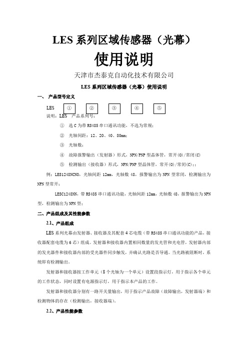
LES系列区域传感器(光幕)使用说明天津市杰泰克自动化技术有限公司LES系列区域传感器(光幕)使用说明一、产品型号定义说明:①选C为带RS485串口通讯功能,不选为常规;②光轴间距:12、20、40、80mm;③光轴数;④故障报警输出(发射器)形式,NPN/PNP型晶体管,常开(O)/常闭(C)⑤检测输出(接收器)形式,NPN/PNP型晶体管,常开(O)/常闭(C);;例:LES1248NCNO,光轴间距12mm,光轴数48,报警输出为NPN型常闭,检测输出为NPN型常开;LESC1248NN,带RS485串口通讯功能,光轴间距12mm,光轴数48,报警输出为NPN 型,检测输出为NPN型;二、产品组成及其性能参数2.1、产品组成LES系列光幕由发射器、接收器及其配套4芯电缆(带RS485串口通讯功能的产品,接收器配套电缆为6芯)组成。
发射器和接收器内置相同数量的发光管和光电管,发射器内部的发光器件和接收器内部的受光器件同步触发,并确认光路是否导通。
当光路被阻断时,系统即有检测输出。
发射器和接收器按工作单元(8个光轴为一个单元)设置段指示灯,用于指示各个单元的工作状态,同时设置有电源指示灯,用于指示本产品的工作。
发射器和接收器分别有一路开关量输出,用于指示产品故障(故障输出,发射器端)和检测物体的存在(检测输出,接收器端)。
2.2、产品性能参数LES三、产品型号及其参数列表3.1、LES(C)12系列3.2、LES(C)20系列3.3、LES(C)40系列3.4、LES(C)80系列3.5、产品外观示意图四、指示灯说明LED指示灯(红色)用于指示产品的工作状态和故障状态,发射器和接收器配置有相同数量的指示灯,其布置图见图4.1。
表4.1 各指示灯功能定义注:若接收器电源指示灯常亮,发射器电源指示灯闪烁/常灭,则发射器和接收器之间通讯异常。
五、产品接线图六、测试说明6.1、接线首先将光幕发射器和接收器按照光幕接线图(见图5.1)接线并检查接线是否正确(接线时必须断开电源),然后将光幕发射器和接收器在有效检测距离内(1.0m ~ 5.5m)面对面放好并对准。
SG-BWS-T4-MT系列安全光幕快速使用手册说明书

SG-BWS-T4-MTSERIESSafety control unit with double mutingQUICK GUIDESAFETY INFORMATIONThe following points must be observed for a correct and safe use of thesafety light curtains of the SG-BWS-T4-MT series:The stopping system of the machine must be electrically controlled. This control system must be able to stop the dangerous movement of the machine within the total machine stopping time T as per par. 3.4 of the complete manual inside the CD and during all working cycle phases.The safety system should be installed and connected by a qualified technician in compliance with the instructions specified in this manual and industry rules.The photocells must be securely installed in a particular position so that access to the dangerous zone is not possible without the interruption of the beams (see 3.3 “General information on sensors positioning” of the complete manual inside the CD). The personnel operating in the dangerous area must be well trained and must have adequate knowledge of all the operating procedures of the safety control unit.The START and TEST buttons must be located outside the protected area because the operator must check the protected area during all Test and Reset operations.Please carefully read the instructions for the correct functioning before powering the SG-BWS-T4-MT.Precautions to be observed for the choice and installation of the deviceMake sure that the protection level assured by the SG-BWS-T4-MT device (Type 4) is compatible with the real danger level of the machine to becontrolled, according to EN 954-1 and EN 13849-1.∙ The outputs (SAFCN) of the ESPE must be used as machine stopping devices and not as commanddevices. The machine must have its own START command. ∙ The dimension of the smallest object to be detected must be larger than the resolution level of theinstalled safety sensors.∙ The ESPE must be installed in a room complying with the technical characteristics indicated in section9 “Technical data” of the complete manual inside the CD. ∙ Do not install the sensors close to strong and/or flashing light sources or close to similar devices. ∙ Strong electromagnetic disturbance might negatively affect device operation. Should this be the casecontact Datalogic Automation Technical Service. ∙ The operating distance of the safety sensors can be reduced in presence of smog, fog or airbornedust. ∙ A sudden change in environment temperature, with very low minimum peaks, can generate a smallcondensation layer on the sensors lenses and so jeopardise functioning.∙ Pay special care when positioning the safety photocells so to offer effective protection. The safetysensors should be installed in such a way that the dangerous area can only be entered after detecting the sensitive area. Photocells position is fixed by normative and must respect measures in Tab. 4 of the complete manual inside the CD.The failure to respect the safety distance reducesor cancels ESPE the protection function.For more detailed information about calculation of safety distance,please refer to the complete manual contained in the CD supplied.CONNECTIONSSIGNAL CONTACT CONNECTION FUNCTIONVDC 1 24 Vdc ext. Power START 2 NO contact toward 24VDC Reset Function TEST/RESET 3 NC contact toward 24VDCTest/Reset functionEDM 4 - NC contact of external relay toward 24VDC (with EDM enabled)- NOT CONNECTED (with EDM disabled)EDM Input0 V 2 0 Vdc ext. Power MUTEN A 6 NO contact toward 24VDC Muting enable MUTEN B 7 NO contact toward 24VDC Muting enable DEFLAMP 8 Warning device positive terminal Lamp failure warningMUTA1 9 PNP output of muting sensor A1 Muting input OVRA1 10 Override A1 NO contact toward 24VDC Override input MUTB1 11 PNP output of muting sensor B1 Muting input OVRB1 12 Override B1 NO contact toward 24VDC Override input MUTA2 13 PNP output of muting sensor A2 Muting input OVRA2 14 Override A2 NO contact toward 24VDC Override input MUTB2 15 PNP output of muting sensor B2 Muting input OVRB2 16 Override B2 NO contact toward 24VDC Override input LAMPA- 17 Negative terminal of muting lamp A Muting lamp output LAMPA+ 18 Positive terminal of muting lamp A Muting lamp output SAFNC11 19Relays output NO 230V 1Safety contact SAFNC21 20 Safety contact LAMPB- 21 Negative terminal of muting lamp B Muting lamp output LAMPB+ 22 Positive terminal of muting lamp B Muting lamp output SAFNC12 23Relays output NO 230V 2Safety contact SAFNC22 24 Safety contact RX1 25 PNP output of receiver photocell 1 (black) Photocell Input RX2 26 PNP output of receiver photocell 2 (black) Photocell Input RX3 27 PNP output of receiver photocell 3 (black) Photocell Input RX4 28 PNP output of receiver photocell 4 (black) Photocell Input TX1 29 TEST of emitter photocell 1 (black) Photocell Output TX2 30 TEST of emitter photocell 2 (black) Photocell Output TX3 31 TEST of emitter photocell 3 (black) Photocell Output TX4 32 TEST of emitter photocell 4 (black) Photocell Output 24VRX12 33 24VDC photocell receivers 1 and 2 (brown) Power supply output 0VRX12 34 0VDC photocell receivers 1 and 2 (blue) Power supply output 24VRX34 35 24VDC photocell receivers 3 and 4 (brown) Power supply output 0VRX34 36 0VDC photocell receivers 3 and 4 (blue) Power supply output 24VTX12 37 24VDC photocell emitters 1 and 2 (brown) Power supply output 0VTX12 38 0VDC photocell emitters 1 and 2 (blue) Power supply output 24VTX34 39 24VDC photocell emitters 3 and 4 (brown)Power supply outputSIGNAL CONTACT CONNECTION FUNCTION 0VTX34 40 0VDC photocell emitters 3 and 4 (blue) Power supply output OSSD11 41 OSSD 1 output of light curtain 1 (grey) Safety light curtain input OSSD21 42 OSSD 1 output of light curtain 2 (grey) Safety light curtain input24LRX12 43 24VDC light curtain receivers 1 and 2(brown)Power supply output0LRX12 44 0VDC light curtain receivers 1 and 2 (brown) Power supply output OSSD12 45 OSSD 2 output of light curtain 1 (pink) Safety light curtain input OSSD22 46 OSSD 2 output of light curtain 2 (pink) Safety light curtain input 24LTX12 47 24VDC light curtain emitters 1 and 2 (brown) Power supply output 0LTX12 48 0VDC light curtain emitters 1 and 2 (brown) Power supply outputNO: Normally Open – NC: Normally ClosedMinimum connection (1 photocell, no EDM, automatic RESTART)The control unit terminals layout and the minimum connection to check system operation are shown below.The photocells set power (blue and brown wires) reaches terminals 33-34, 37-38 as specified in the table in the complete manual inside the CD.For the other configuration (for example concerning muting and override) please refer to section 4 in the complete manual inside the CD.SIGNAL CONTACT CONNECTION FUNCTIONext. PowerVdcVDC 1 24TEST/RESET 3 24 Vdc ext. Test function0 V 2 0 Vdc ext. PowerRX1 25 PNP output of receiver photocell 1 (black) Photocell InputTX1 29 TEST of emitter photocell 1 (black) Photocell OutputRX2 26 TX2 (30) Photocell InputRX3 27 TX3 (31) Photocell InputRX4 28 TX4 (32) Photocell InputOSSD11 41 OSSD21 (42) Safety light curtain input OSSD21 42 24LRX12 (43) Safety light curtain input OSSD12 45 OSSD22 (46) Safety light curtain input OSSD22 46 24LTX12 (47) Safety light curtain input24VRX12 33 24VDC power supply RX (brown) Power supply output 0VRX12 34 0VDC power supply RX (blue) Power supply output24VTX12 37 24VDC power supply TX (brown) Power supply output0VTX12 38 0VDC power supply TX (blue) Power supply outputSG-BWS-T4-MT as MPCE (Machine Primary Control Equipment)SG-BWST-T4-MT can be directly used as a Machine Primary Control Equipment (MPCE) since it’s equipped with internal monitored relays which can switch a maximum load of 3,6A at 250V. The proper connections are shown in the next figure.SG-BWS-T4-MT as external safety relays controllerWhen utilizing SG-BWS-T4 for external safety relays control proper connections are shown in the following figure.K1K2SAFCN11 (19)SAFCN21 (20)SAFCN12 (23)SAFCN22 (24)B W S -T 4-M TMain Supply VoltageT o machine powerALIGNMENT SAFETY DEVICESOnce all components are in place and connected, emitters and receivers shall be mutually aligned.In alignment mode, the OSSD safety outputs are open. The alignment mode and relevantprocedure are described here below:∙Cut off control unit power supply.∙Power on the control unit while holding pressed Test button (Test contact open)∙The 7-segment display shows the first device to be aligned (Photocells 1-4, light curtains 5-6)∙∙The control unit will run the initial test routines and display a countdown, the display will then turn off and the control unit will switch to NORMAL OPERATION status ( NORMAL).Now carry out the following inspections:∙The ESPE stays in SAFE mode during photocells and light curtains beam interruption using the suitable “Test Piece”, along the entire protected area.∙Enabling the TEST function, the OSSD outputs should open ( SAFE and the controlled machine stops).∙The response time upon machine STOP (including response time of the ESPE and of the machine) is within the limits defined for the calculation of the safety distance (see section 3 “Installation” of the complete manual inside the CD).∙The safety distance between the dangerous areas and the safety sensors is in accordance with the instructions included in section 3 “Installation” of the complete manual inside the CD.∙Access of a person between sensors and machine dangerous parts is not possible nor is it possible for him/her to stay there.∙Access to the dangerous area of the machine from any unprotected area is not possible.During alignment or normal operation, make sure that the photocells connected to the same or other units do not interfere with each other. Should you find interference, change their position, for instance you could set some emitter sets on the side of the other receivers. In case of interference, the control unit will lock out and display the relevant error code.DIP-SWITCHES CONFIGURATIONAt control unit top part you will find two units made up of 8 Dip-Switches each: SG-BWS-T4-MT safety rating requires installation of two switches for setting up each function, so that the setup defined for the first unit shall be set even for the second unit.The table below is a list of possible settings selectable through the 8 Dip-Switches available.DIP PURPOSE OFF(Default) ON1 ENABLEEDM ENABLED DISABLED2 RESETMODE AUTOMATIC MANUAL3 MUTING TIME-OUT 10 MINUTES INFINITY4 MUTINGDIRECTION T L5 TRIGGEROVERRIDE LEVEL FRONT6 MUTINGSELECTIONVedi tabella seguente7 MUTINGSELECTION8 MUTINGSELECTIONDatalogic Automation supplies the control unit in the “Default” setup (all switches OFF).The Dip-Switches 6-7-8 allow user to couple the single devices to the 2 muting channels available on the SG-BWS-T4-MT.Activating a channel muting involves temporarily suspending the safety function of all devices associated to it. Extreme care is hence required when associating channel to devices: any dangerous settings shall be avoided.DIAGNOSTICS AND SIGNALLINGSG-BWS-T4-MT is equipped with a user interface featuring 3 LEDs and a 7-segment display.LED INDICATIONPOWER Device is powered correctlyNORMAL No danger: safety outputs closedSAFE Danger or fault: safety outputs openThe 7-segment display shows detailed information on control unit current status Normal operation signallingINDICATION STATUS DESCRIPTION TO DO POWERNORMALSAFE NORMALOPERATIONThe Override function is active on channel A, B or both. The muting indicator isflashing.POWERNORMALSAFE NORMALOPERATION One of the two muting lampsis disconnected or faulty(only one muting channel isactive).Change the faulty lamp.It is not necessary torestart.POWER⇨NORMALSAFEInterlockWaiting for the STARTcommand in manual resetmodePush reset controlPOWER/ NORMAL/ SAFE NORMALOPERATION/SAFE The decimal point indicates that the EDM function isactive (see 4.7)POWER NORMALSAFESAFE TEST push-button pressed(contact 3 open)Check TEST push-button connections (see4.9)Failure state signallingINDICATION STATUS DESCRIPTION WHATTODO POWERNORMALSAFEOff Power disconnected or innerfuse blown due to overload.Check power supply. Iferror persists, pleasecontact the TechnicalService.POWER NORMAL SAFEINTERNALDEVICEMONITORINGFAILURELOCKOUTInternal relays contactsmonitoring test has failed.Reset the control unit(see 4.6). If errorpersists, please contactthe Technical Service.POWER NORMAL SAFE INTERNALOSSDFAILURELOCKOUTInternal OSSD test routinehas failed.Reset the control unit(see 4.9). If errorpersists, please contactthe Technical Service.INDICATION STATUS DESCRIPTION TODO POWERNORMALSAFE EDM FAILURELOCKOUT EDM test has failedCheck EDMconnections (see 4.7)or disable EDMfunction (see 4.4) ifyou do not wish to useit.POWERNORMAL SAFEMICRO-PROCESSORFAILURELOCKOUTOne of microprocessor testshas failedDisconnect powersupply and reconnectit. If error persists,please contact theTechnical Service.POWERNORMALSAFE DIPSWITCHES FAILURE LOCKOUTThe Dip-Switches settingconsistency test has failedMake sure that thesettings of the two setsof switches is the same(see 4.4). Reset thecontrol unit (see4.9). If error persists,please contact theTechnical Service.POWERNORMAL SAFE RESTARTFAILURELOCKOUTStart signal time-out tripped.Make sure you hold theStart button depressedfor less than 5s.POWER NORMAL SAFESENSOR FAILURE LOCKOUT Test of indicated safetysensor has failed.- F 1-4: Make surethere is no interferenceacross differentphotocell sets.- F 5-6: Check lightcurtains OSSDconnections (see4.5).POWERNORMAL SAFELAMPFAILURELOCKOUTMuting lamp faulty ordisconnected.Change the faultylamp, then Reset thecontrol unit (see4.9)POWERNORMALSAFE OVERRIDEFAILUREThe Override commandactivation test has failed(push-buttons not pressed atthe same time)Press the Overridepush-buttons at thesame time.DECLARATION OF CONFORMITYWe DATALOGIC AUTOMATION declare under our sole responsibility that these products are conform to the 2006/42/EC and successive amendments.WARRANTYDATALOGIC AUTOMATION warrants its products to be free from defects.DATALOGIC AUTOMATION will repair or replace, free of charge, any product found to be defective during the warranty period of 36 months from the manufacturing date.This warranty does not cover damage or liability deriving from the improper application of Datalogic Automation products. DATALOGIC AUTOMATION srlVia Lavino 265 - 40050 Monte S.Pietro - Bologna – ItalyTel: +39 051 6765611 - Fax: +39 051 6759324 DATALOGIC AUTOMATION cares for the environment: 100% recycled paper.DATALOGIC AUTOMATION reserves the right to make modifications and improvements without prior notification.© 2009 – 2014 Datalogic Automation - ALL RIGHTS RESERVED - Protected to the fullest extent under U.S. and international laws. • Copying, or altering of this document is prohibited without express written consent from Datalogic Automation. Datalogic and the Datalogic logo are registered trademarks of Datalogic S.p.A. in many countries, including the U.S.A. and the E.U.830000502 rev.C。
Schneider Electric XUSL4E30H016N 安全光幕说明书

T h e i n f o r m a t i o n p r o v i d e d i n t h i s d o c u m e n t a t i o n c o n t a i n s g e n e r a l d e s c r i p t i o n s a n d /o r t e c h n i c a l c h a r a c t e r i s t i c s o f t h e p e r f o r m a n c e o f t h e p r o d u c t s c o n t a i n e d h e r e i n .T h i s d o c u m e n t a t i o n i s n o t i n t e n d e d a s a s u b s t i t u t e f o r a n d i s n o t t o b e u s e d f o r d e t e r m i n i n g s u i t a b i l i t y o r r e l i a b i l i t y o f t h e s e p r o d u c t s f o r s p e c i f i c u s e r a p p l i c a t i o n s .I t i s t h e d u t y o f a n y s u c h u s e r o r i n t e g r a t o r t o p e r f o r m t h e a p p r o p r i a t e a n d c o m p l e t e r i s k a n a l y s i s , e v a l u a t i o n a n d t e s t i n g o f t h e p r o d u c t s w i t h r e s p e c t t o t h e r e l e v a n t s p e c i f i c a p p l i c a t i o n o r u s e t h e r e o f .N e i t h e r S c h n e i d e r E l e c t r i c I n d u s t r i e s S A S n o r a n y o f i t s a f f i l i a t e s o r s u b s i d i a r i e s s h a l l b e r e s p o n s i b l e o r l i a b l e f o r m i s u s e o f t h e i n f o r m a t i o n c o n t a i n e d h e r e i n .Product data sheetCharacteristicsXUSL4E30H016NXUSL type 4 - For hand protection - Stdsensing range - Hp = 160 mm, R=30mmMainRange of product Preventa Safety detection Product or component typeSafety light curtain type 4Device short name XUSL4EOutput type2 safety outputs OSSD solid-state PNP (integrated arc suppression)Product specific appli-cation For hand protection [R] Resolution 30 mm[Sn] nominal sensing distance0...4 m by cabling 0...12 m by cabling [Hp] Height protected 160 mm Number of beams 8Type of start / restart Automatic ManualExternal Device Moni-toring (EDM)Selected by wiringComplementaryDetection system Transmitter-receiver system Response time 4 msKit composition1 user guide with certificate of conformity on CD-ROM 1 transmitter(s)1 receiver(s)Adjustable mounting bracket(s)[EAA] effective aperture angle +/- 2.5 ° at 3 m EmissionIR LED (λ = 950 nm)[Us] rated supply voltage 24 V DC (+/- 20 %)SupplyPower supply must meet requirements of IEC 60204-1Power supply must meet requirements of IEC 61496-1[Ie] rated operational current 2 ACurrent consumption900 mA with maximum load (receiver)42 mA (transmitter)83 mA no-load (receiver)42 mA no-load (transmitter)Output current limits 0.4 A for safety outputs OSSD Output voltage 24 V Output circuit type DC Voltage drop <= 0.5 VLocal signalling 2 dual colour LEDs (receiver)1 multi-colour LED (transmitter)Electrical connection 1 male connector M12 8 pins (receiver)1 male connector M12 5 pins (transmitter)Function availableLED display of operating modes and faultsMuting through external safety module XPSLCMUT1160Test Marking CEMaterialEnd caps : polypropylene Front panel : polycarbonate Casing : aluminium Housing colourRAL 3000 : redFixing mode By fixing bracketsProduct weight0.4 kgOffer type Standard distanceEnvironmentDirectives89/336/EEC - electromagnetic compatibility2002/96/EC - WEEE directive2002/95/EC - RoHS directive98/37/EEC - machinery89/655/EEC - work equipmentProduct certifications CECULusTÜVSafety level (correctly wired)PL = e conforming to EN/ISO 13849-1Category 4 conforming to EN/ISO 13849-1SILCL 3 conforming to IEC 62061SIL 3 conforming to IEC 61508Type 4 conforming to IEC 61496-1Optical characteristic Resistance to light disturbance conforming to EN/IEC 61496-2 Mission time20 yrSafety reliability data PFHd = 7.8E-9 1/h conforming to IEC 61508Ambient air temperature for operation-10...55 °C14...131 °FAmbient air temperature for storage-25...70 °C-13...158 °FRelative humidity<= 95 % without condensationIP degree of protection IP67IP65Shock resistance10 gn for 16 ms conforming to IEC 61496-1Vibration resistance0.35 +/- 0.05 mm (f = 10...55 Hz) conforming to IEC 61496-1Offer SustainabilitySustainable offer status Green Premium productRoHS (date code: YYWW)Compliant - since 1425 -Schneider Electric declaration of conformityREACh Reference not containing SVHC above the thresholdProduct environmental profile Available Download Product EnvironmentalProduct end of life instructions Available Download End Of Life ManualContractual warrantyPeriod18 monthsDimensions Drawings DimensionsBrackets DimensionsMounting and Clearance Mounting and Clearance(1)Insert(2)Bracket(3)Washer(4)Spring washer(5)NutConnections and SchemaWiring DiagramsTransmitter Connections(1)+24 Vdc(2)Configuration_0(3)0 Vdc(4)Configuration_1(5)FEReceiver Connections(1)OSSD1(2)+ 24 V(3)OSSD2(4)Configuration_A(5)K1_K2 Feeback/Restart(6)Configuration_B(7)0 Vdc(8)FEReceiver Configurations and Operating ModesAutomatic Start/RestartWithout External Device Monitoring (EDM) feedback loopWith External Device Monitoring (EDM) feedback loopManual Start/RestartWithout External Device Monitoring (EDM) feedback loop(1)RestartWith External Device Monitoring (EDM) feedback loop(1)RestartConnection SchematicsStandalone ApplicationXUSL4E light curtains are conforming to Type 4 (IEC 61496-1), SIL3 (IEC 61508) - SILCL3 (IEC 62061) and PLd- Cat.4 (EN ISO 13849-1:2008)Example of wiring diagram with manual start, external device monitoring and low range(1)Power supply(2)XUSL Receiver(3)XUSL transmitter(4)Low range(5)StartThe contactors K1/K2 must have :*Normally closed mirror contact, according to IEC 60947-4-1 for power contactors*Linked contacts (or force guided contacts), according to IEC 60947-5-1 or EN 50205 for auxiliary contactors or control relays。
Datalogic 激光扫描仪和光幕用户手册说明书
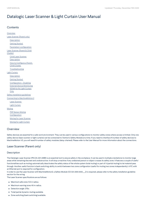
Safety devices are essential for a safe work environment. They can be used in various configurations to monitor safety zones where access is limited. Only one safety device (laser scanner or light curtains) can be connected to Vention’s Safety Module at a time. If you need to interface N number of safety devices to MachineMotion V2, you will need N number of safety modules (daisy-chained). Please refer to the User Manual for more information about the connections.
To set parameters, select Configuration to access a drop-down menu. For each item on the drop-down menu, enter the desired values in the appropriate fields (highlighted in yellow). More details are provided for each parameter below.
Maximum safe zone: 5.5 m radius. Maximum warning zone: 40 m radius. Detection angle: 275o. Total/partial dynamic muting available. Zone switching (bank switching) available.
安全光幕使用说明

安全光幕使用说明
接线如下图:
发射器一端黄色线不接,接收器一端绿色线与0V的蓝色线短接。
OS1、OS2为2个常闭输出端,所以当光幕被遮挡时OS1、OS2输出为0V。
调试:
1.安装前先在现场或实验室,静态、近距离地调试一遍,在0.5米的情况下,显示的光强显示应大于等于“8”
2.若光栅是垂直安装的,则应保证水平高度一致,通电后,光栅的显示单元,会先点亮所有显示,然后再进入正常工作显示。
3.调整发射单元角度及倾角,再调整接收单元,如有必要,可循环调整直至接收单元显示的接收强度达到最大。
4.试棒测试
凡安全装置安装完毕或每次检修完毕后,均须应用试棒作最终测试,取一根与安全装置分辨率尺寸相同的试棒,在靠近光栅发射器、光栅接收器及二者中间,将试棒自上而下和自下而上移动三次,此时光栅接收器的数码管应依次显示被遮光电管的序号(小于等于8光点),或被遮光电管的印板序号(大于8光点)。
状态灯应一直显示红色不能显示一次绿灯,若有异常情况,应请专业人员进行检修。
故障处理:
如果发射单元或接收单元显示报警,可按下表处理:SSGS20安全光栅故障及处理(发射单元)
SSGS20安全光栅故障及处理 (接收单元)
安装支架简图:。
光幕传感器说明书
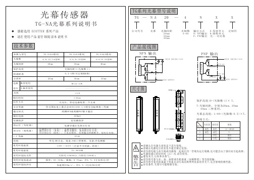
TG -N A4 0系 列 4/ 6/ 8/ 10 至80
NPN 输出
棕色 线 电源 正极12-24VDC
负载 自恢 复保 险丝 黑色 线 输出
PNP 输出
V+
棕色 线 电源 正极12-24VDC
黑色 线 输出
主控电路
主控电路
40 mm
自恢 复保 险丝 V+
0V 自恢 复保 险丝 白色 线 输出
白色 线 输出 自恢 复保 险丝 负载
使用环境湿度
有短路保护
电源导通红色指示灯亮
电源指示灯(红色):电源导通时,红色指示灯点亮。 输出指示灯(黄色):输出导通时,黄色指示灯点亮。 同 步 指 示 灯 (绿 色 ) : 上 电 自 检 时 , 发 现 输 出 回 路 断 开 , 绿 色 灯 闪 烁 。
4Pin M 12连接器
发射器 棕色 蓝色 -------
接收器 棕色 蓝色 黑色 白色
接线 12~24V DC V输出 输出
IP 40 外 壳:铝 合 金 , 端 盖:A BS 工 程 塑 料 , 支 架:冷 轧 钢 板 -1 0℃ ~+5 5℃ ( 注 意 不 可 结 露 、 结 冰 )
15 ~85 % RH
4-M 4 ,安装孔
使用环境抗光性 使用环境抗震动 使用环境抗冲击
E :发 射 单 元 R :接 收 单 元 无:一 对 光 幕
定制符
技术参数
参数与型号 光轴数 光轴间距 保护高度 检测距离
分辨率
产品接线图
TG -N A2 0系 列 4/ 8/ 12 /1 6至80
20 mm
TG -N A3 0系 列 4/ 6/ 8/ 10 至80
30 mm 光 轴 间 距 ×(光 轴 数-1 ) 0. 4 - 4米(可 定 制 到6米)
欧姆龙 F3SJ-A P系列 安全光幕 说明书
ḋ 㓪 SCHG-C-718BF3SJ-A P ㋏ (Ver.2) 㓪 SCHG-C-718B F3SJ-A P ㋏ (Ver.2)㓪 ˖SCHG-C-718B200607S01ㅔҟ䇶 䌁фF3SJ㋏ ˄ҹ ㅔ⿄ĀF3SJā˅DŽ䖭 ㅔ ҟ㒡F3SJⱘ⫼⊩DŽՓ⫼F3SJ 㽕⊼ ҹϟ ⚍ ˖g 䆕F3SJⱘ 㗙 ❳ 㺙ⱘ ⱘĀ䋷ӏҎāDŽg ЁՓ⫼ⱘ 䆡Ā䋷ӏҎā 䌘䋼ⱘǃ㒣䖛 ⱘǃ 䋳䋷 䆕ⱘ䆒䅵ǃ 㺙ǃ ǃ㓈 㕂ⱘ 䖛ⱘĀ āⱘҎ DŽg 䆒 ḍ ⱘ 㺙⦃ ǃ 㛑 㛑 ℷ⹂Փ⫼F3SJDŽg䋷ӏҎ 㺙 䖯㸠 ⱘ亢䰽䆘Ԅ 䗖 Ѣ ѻ DŽg 㺙 ѻ ˈ䅸ⳳ䯙䇏 ˈ⧚㾷 ⫼ 䗄DŽ㕂 ӏԩ䳔㽕ⱘ 䛑㛑⫼ 䯙ⱘ DŽiF3SJ-A 用户手册简介简介C 1.单独使用F3SJ-A 传感器将不能获得日本劳动卫生法的第44-2条的类型批准。
必须将它用在一个系统中。
因此,在日本把F3SJ-A 当作这个法律的第42条所描述的“压力或剪切机器的安全系统”使用时,系统必须获得类型批准。
2.根据欧盟(EU )的机械指令索引附件IV ,B ,安全部件,第1条,F3SJ-A 是光电保护设备(ESPE )。
3.F3SJ-A 符合下列法规和标准(1)EU 法规机械指令 98/37/ECEMC 指令 89/336/EEC(2)欧洲标准EN61496-1(类型4 ESPE ),prEN61496-2(类型4 AOPD ),EN61508-1~-7(SIL3)(3)国际标准IEC61496-1(类型4 ESPE ),IEC61496-2(类型4 AOPD ),IEC61508-1~-7(SIL3)(4)JIS 标准JIS B 9704-1(类型4 ESPE ),JIS B 9704-2(类型4 AOPD )(5)北美标准UL61496-1(类型4 ESPE ), UL61496-2(类型4 AOPD ), UL508, UL1998, CAN/CSA 22.2 No.14, CAN/CSA 22.2 No.0.84.F3SJ-A 从EU 公认的认证机构TÜV-PS 取得了以下的认证:•EU 类型检验符合EU 机械指令,类型4 ESPE (EN61496-1),类型4 AOPD (prEN61496-2)•EMC 证书(测试的电源:OMRON S82K )..•TUV-PS 类型批准,类型4 ESPE (EN61496-1),类型4 AOPD (prEN61496-2),SIL1,2,3(EN61508-1~-7),应用:EN954-1 分类B ,1,2,3,45.F3SJ-A 计划将从第三方评估机构UL 取得符合美国和加拿大安全标准的UL 证书。
LES系列光幕使用说明
LES系列区域传感器(光幕)使用说明天津市杰泰克自动化技术有限公司LES 系列区域传感器(光幕)使用说明一、 产品型号定义说明:LES 产品系列号;① 选C 为带RS485串口通讯功能,不选为常规; ② 光轴间距:12、20、40、80mm ; ③ 光轴数;④ 故障报警输出(发射器)形式,NPN/PNP 型晶体管,常开(O)/常闭(C) ⑤ 检测输出(接收器)形式,NPN/PNP 型晶体管,常开(O)/常闭(C);;例:LES1248NCNO ,光轴间距12mm ,光轴数48,报警输出为NPN型常闭,检测输出为NPN 型常开;LESC1248NN ,带RS485串口通讯功能,光轴间距12mm ,光轴数48,报警输出为NPN 型,检测输出为NPN 型;二、产品组成及其性能参数2.1、产品组成LES 系列光幕由发射器、接收器及其配套4芯电缆(带RS485串口通讯功能的产品,接收器配套电缆为6芯)组成。
发射器和接收器内置相同数量的发光管和光电管,发射器内部的发光器件和接收器内部的受光器件同步触发,并确认光路是否导通。
当光路被阻断时,系统即有检测输出。
发射器和接收器按工作单元(8个光轴为一个单元)设置段指示灯,用于指示各个单元的工作状态,同时设置有电源指示灯,用于指示本产品的工作。
发射器和接收器分别有一路开关量输出,用于指示产品故障(故障输出,发射器端)和检测物体的存在(检测输出,接收器端)。
LES2.2、产品性能参数三、产品型号及其参数列表3.1、LES(C)12系列3.2、LES(C)20系列3.3、LES(C)40系列3.4、LES(C)80系列3.5、产品外观示意图()系列光幕机械尺寸示意图1()系列光幕机械尺寸示意图2()系列光幕机械尺寸示意图3四、指示灯说明LED指示灯(红色)用于指示产品的工作状态和故障状态,发射器和接收器配置有相同数量的指示灯,其布置图见图4.1。
图4.1 指示灯布置图表4.1 各指示灯功能定义注:若接收器电源指示灯常亮,发射器电源指示灯闪烁/常灭,则发射器和接收器之间通讯异常。
威格士 SAFEasyTM 光幕 SF2系列说明书

•Integrated light curtains for PRESENCE CONTROL PROTECTION •50 and 90 mm resolution and operating distance up to 15 m •31 x 32 mm compact profile•Versions with automatic or manual RESTARTThe SAFEasy TM light curtains of the SF2series, according to the IEC 61496-1 and IEC 61496-2 st andards, are very suit able for presence detection of operators exposed to risks.Different models are available with nine st andard heights ranging from 300 to 1500 mm, with 50 or 90 mm resolution and an operating distance reaching 15 m.The emitter and receiver unit s are optically synchronised and cont ain all the control circuits, test input and two safety outputs inside the housing.The connection with the machine stopping circuit s are guaranteed by unshielded M12 4-pole connectors for the emitter and M12 5-pole connectors for the receiver.The SAFEasy TM light curtains of the SF2series have also integrated the test function, automatically activated every 0.5 seconds, without stopping the machine's working cycle.A wide range of industrial applications, requiring operator safety , can be solved by the SAFEasy TM light curt ains, thanks to the extremely comp act dimensions (31x32 mm), easy installation and excellent performances.SF2-PRESENCE CONTROL SERIESSAFEasy ™TYPE 2 LIGHT CURTAINSS A F E T Y D E V I C E SPresence control is obt ained positioning horizontally the safety light curt ain. This inst allation allows to continuously control the presence of an obst acle inside a specific area. This is a p articularly useful solution when dangerous area, not visible from the machine control points, has to be protected.DIMENSIONSRECEIVER (RX)EMITTER (TX)CONNECTIONSOSSD1 PNPOSSD2 PNP0 V+24 Vdc+24 Vdc1= brown = +24 Vdc 2= white = OSSD13= blue = 0V 4= black = OSSD25=grey = TEST **= automatic RESTART (X version) TEST/RESET function= manual RESTART (Y version) TEST/RESTART/RESET functionCONTROLLEDHEIGHT L 1 L 2 (mm)300374294450521441600668588750815735900962882105011091029120012561176135014031323150015501470L 323153.314.9M 12 x 11L 2mm+24 VdcNOT USED NOT USED0 V 1= brown = +24 Vdc 2= white = NOT USED 3= blue = 0V4= black = NOT USEDPower supply (Vdd):24 Vdc ± 20% (SELV /PELV)Consumption:50 mA max. / 1 W (emitter)90 mA max. / 2.5 W (receiver without load)Light emission: infrared LED 880 nm Optic diameter:Ø 18 mmNumber of controlled beams: refer to table 1Optic interaxis: 37,5 mm (SF2-50); 74 mm (SF2-90) Resolution:50 / 90 mm Controlled height: refer to table 2Operating distance: 0.2 ... 15 mReceiver inputs:external switches for Test and Restart Receiver indicators: 2 yellow ALIGNMENT LEDs red BREAK LED green SAFE LEDEmitter indicators: yellow WORKING UNIT CHECK LED green POWER ON LED Output type:2 PNPshort-circuit protection:max.1.4 A at 55°Cmin. 1.2 A at 0 °COutput current (for all loads): 500 mA max. per output Output voltage ON min.:Vdd - 1 V Output voltage OFF max.:0.2 V Leakage current:0.65 mA Capacitive load (pure):100 nF max.Resistive load (pure):60 Ωmin.Response time:refer to table 3Receiver connection: M12 5-pole connector Emitter connection: M12 4-pole connector Safety category:type 2Electrical protection: class 1Mechanical protection: IP65 (EN 60529)IP67(connector part)Housing material:painted aluminium Cap end material:PBT Lens material:PMMACable length:50 m max * (at 100nF capacitive load and Vdd=24V)M12 conductors (according to EN 50044, EN 60947-5-2) poles Ø = 32x0.1mm, external Ø = 0.5mm Weight:1 Kg. max. / m of total height Operating temperature:0 ...+55 °C Storage temperature: -25 ... +70 °CReference standards:EN 954-1, IEC 61496-1, IEC 61496-2* = if a longer cable has to be used, please verify that the same specifications are respectedTECHNICAL DATATABLESModelSF2-50SF2-90SF2 height 30095SF2 height 450 137SF2 height 600179SF2 height 7502111SF2 height 900 2513SF2 height 1050 2915SF2 height 12003317SF2 height 1350 3719SF2 height 15004121Table 2: CONTROLLED HEIGHT (mm)ModelSF2SF2 height 300334SF2 height 450 481SF2 height 600628SF2 height 750775SF2 height 900 922SF2 height 1050 1069SF2 height 12001216SF2 height 1350 1363SF2 height 15001510Table 1:NUMBER OF CONTROLLED BEAMSTable 3: RESPONSE TIME (ms)ModelSF2SF2 height 30015SF2 height 450 16SF2 height 60017SF2 height 75018SF2 height 900 19SF2 height 1050 20SF2 height 120022SF2 height 1350 23SF2 height 1500 24II3DPlease refer also to Safey Device Accessories Distributed by:。
投影机标准操作手册说明书

DS272/DS27BAA/MS580/BS570DX273/DX27CAA/MX581/BX571DW275/DW27EAA/MW584/BW572DH278/DH27HAA/MH588/BH577DX283-ST/DX28CAA/MX595ST/BX585STDW284-ST/DW28DAAST/MW596ST/BW586ST ӦFCC 声明此设备经测试证实,符合 FCC 规则第 15 部分关于 B 级数字设备的限制要求。
这些限制的目的是为了在居住区安装时提供合理保护以防止有害干扰。
此设备会生成、使用和辐射无线电频率能量,如果不按照指示进行安装和使用,可能会对无线通信产生有害干扰。
但本公司不保证在特定安装情况下不产生干扰。
如果此设备确实对无线电或电视接收造成有害干扰 (通过关闭后再打开存在疑问的设备来确定),建议用户尝试采取以下一项或多项措施来排除干扰:•调整接收天线的方向或位置•增大设备和接收器之间的间距•将设备和接收器分别连接到不同的电路插座上•咨询经销商或经验丰富的专业无线电/电视技术人员以获取帮助。
此设备符合 FCC 规则第 15 部分的要求。
其运行须满足以下条件:1.此设备不会产生有害干扰,且2.此设备必须承受任何干扰,包括可能导致意外操作的干扰。
安全说明在使用投影机前,请阅读所有这些指导说明,并妥善保管以备日后参考。
1.阅读指导说明在使用设备前,应阅读所有安全和使用指导说明。
2.注意和警告应遵循使用指导说明中的所有注意和警告。
3.清洁在清洁之前,从墙壁电源插座上拔掉投影机电源线插头。
使用湿布擦拭投影机外壳。
请勿使用液体或烟雾清洁剂。
4.附件切勿将投影机置于不稳的推车、架子或桌子上。
产品可能掉落,导致其严重损坏。
将(投影机、附件和选配件)的塑料包装材料放在儿童够不到的地方,否则包装袋可能导致窒息死亡。
对于婴幼儿更要特别注意。
5.通风此投影机配有进气和排气通风孔。
请勿堵塞这些开口或者在开口附近放置任何物品,否则内部可能积聚热量,并导致画面质量下降或投影机损坏。
OMRON F3SL长距离检测型安全光幕 说明书

产品线 .................................F-24共通注意事项 ........................ 后-2技术指南 (465)相关信息长距离检测型安全光幕F3SL种类(交货期请向经销商咨询)本体附件(另售)专用电缆(请为发光器和受光器各定购1个)反射镜(检测距离衰减率12%)电缆长规格型号发光器用受光器用10m 连接器型F39-JL10A-L F39-JL10A-D 15m F39-JL15A-L F39-JL15A-D 30mF39-JL30A-LF39-JL30A-D镜子材质宽(mm)厚(mm)长(mm)型号玻璃镜子14532406F39-MLG0406610F39-MLG0610711F39-MLG0711914F39-MLG09141,067F39-MLG10671,219F39-MLG12191,422F39-MLG14221,626F39-MLG16261,830F39-MLG18302,134F39-MLG213420m 的长距离检测适用于大型设备及传输线侵入检测的人体检测用(4级)安全光幕■符合IEC 标准、EN 标准、北美标准,由TÜV 取得符合EC 设备指令的EC 认可,可作为符合北美劳动安全的现场所要求的OSHA 规范的安全防护装置使用■无需另备专用控制器。
通过传感器单体可实现人体侵入检测功能。
■备有防止输出自动复位的「启动/重启互锁功能」。
■备有浮动消隐功能(使不特定的1或2光轴无效化的功能)及通道选择(固定消隐:使指定光无效化功能)■内置MPCE (外部继电器)监视功能。
无需控制器便可进行反馈检测。
请参照270页的「请正确使用」。
额定值/性能*1.ESPE(Electro-Sensitive Protective Equipment)*2.AOPD(Active Opto-electronic Protective Devices)项目型号F3SL-A0351P30F3SL-A0523P30F3SL-A0700P30F3SL-A0871P30F3SL-A1046P30F3SL-A1219P30F3SL-A1394P30F3SL-A1570P30F3SL-A1746P30F3SL-A1920P30F3SL-A2095P30检测距离0.3~20m 光轴间距离22mm 光轴数1624324048566472808896检测范围351mm 523mm 700mm 871mm 1,046mm 1,219mm 1,394mm 1,570mm 1,746mm 1,920mm 2,095mm 最小检测物体不透明体φ30mm 以上(浮动消隐时为φ52/φ74)指向角发光器 受光器:各±2.5°以内(检测距离3m 以上,根据IEC61496-2)光源(发光波长)红外发光二级管(850nm)电源电压DC24V ±20%纹波(p-p )5%接通电源后启动时间3s 以下消耗电流发光器:285mA 以下, 受光器:1.4A 以下(含负载输出电流)控制输出PNP 晶体管输出X2输出,负载电流500mA 以下(残留电压2V 以下)(因电缆延长引起的电压下降除外)入光时ON 辅助输出与控制输出信号相同:PNP 晶体管输出X1输出(非安全输出),负载电流100mA 以下(残留电压1V 以下)(因电缆延长引起的电压下降除外)保护电路输出负载短路保护,电源反接保护安全相关功能・启动/重启互锁功能 [通过切换开关可以选择有效/无效]・消隐功能①通道选择(固定消隐) ②浮动消隐③无消隐(工厂出货时)[通过切换开关可进行①、②、③、的选择。
红外扫描光幕说明书
红外扫描光幕说明书
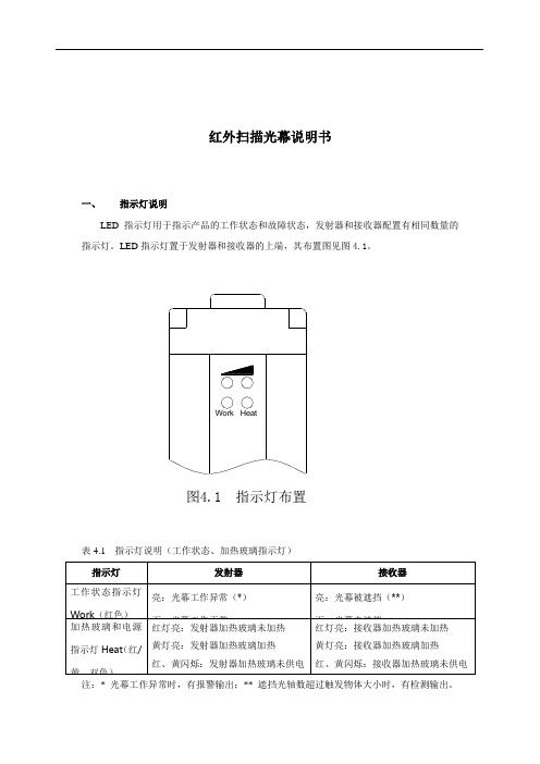
一、指示灯说明
LED指示灯用于指示产品的工作状态和故障状态,发射器和接收器配置有相同数量的指示灯。
LED指示灯置于发射器和接收器的上端,其布置图见图4.1。
图4.1 指示灯布置
表4.1 指示灯说明(工作状态、加热玻璃指示灯)
注:* 光幕工作异常时,有报警输出;** 遮挡光轴数超过触发物体大小时,有检测输出。
表4.2 指示灯说明(接收光束强弱指示灯)
二、光幕外形尺寸和接线图
1、光幕外形尺寸如图5.1;
2、光幕接线图如图5.2。
图5.1 发射器和接收器外形尺寸
第 1 页。
GuardShield Micro 400 安全光幕 说明书
GuardShield™ Micro 400 安全光幕用户手册䞡㽕⫼ 乏ⶹ⠜⠽ 䗄ⱘѻ ⊯ⱘ⫼䗨ˈ ℸˈ䋳䋷 ⫼ Փ⫼ 䆒 ⱘҎ 乏⹂ 䞛 ⾡ 㽕ⱘℹ偸ˈ 䆕↣ϔ乍 ⫼ ⫼䗨䛑⒵䎇 㛑Ϣ 㽕∖ˈ ˖ ⾡䗖⫼⊩ ǃ㾘㣗 DŽ⠜⠽ ⠜ ˈ 㒣㔫 䶺 㞾 䆌 ϡ 䚼 䚼 ⠜⠽ⱘ DŽ Ёˈ Ӏ 㽕ⱘ њ䇈 ˈҹ ⶹ ⊼ џ乍DŽЁⱘ 㾷ǃ 㸼ǃ ՟ǃ ՟ҙկ⼎㣗⫼䗨DŽ⬅Ѣ⡍ ⱘ 㺙 Ӯ 䆌 ㋴ 㽕∖ˈ ℸˈ㢹⫼ 䰙Փ⫼ѻ ✻ Ё 䗄 ՟ˈ㔫 䶺 㞾 ϡ ӏԩ䋷ӏ˄ ⶹ䆚ѻ ⊩ 䋷ӏ˅DŽSafety Guidelines for the Application, Installation and Maintenance of Solid-State Control 䆒 ⱘ ⫼ǃ 㺙Ϣ㓈 ˈ ⠜ ˖SGI-1.1 ⱘ㔫 䶺 㞾 䫔 ㋶ 䗄њ 䆒 ⬉䆒 П䯈ⱘϔѯ䞡㽕 DŽ ⫼ ⠜⠽Ё 䗄ⱘѻ ˈ 㗗㰥䖭ѯ DŽ䆂 ⫼ ˈҹ Փ⫼DŽ䆚 䰽⦃ ϟ 㛑 㟈⟚⚌ˈ䖯㗠䗴 Ҏ Ӹѵǃ䋶ѻ 㒣⌢ ⱘ㸠Ў ⱘ DŽ䆚 ⫼ ⧚㾷ѻ 䞡㽕⫼ⱘ DŽ䆚 㛑Ӯ 㟈Ҏ Ӹѵǃ䋶ѻ 㒣⌢ ⱘ㸠Ў ⱘ DŽ⊼ ヺ ⹂ 䰽ǃ䙓 њ㾷 㛑ⱘ DŽ㾺⬉ 䰽ԡѢ䆒 ՟ ˈ偅 ⬉ 㸼䴶 䚼ⱘ ㅒˈ 䝦ҎӀ 㛑 䰽⬉ DŽ⚻Ӹ 䰽ԡѢ䆒 ՟ ˈ偅 ⬉ 㸼䴶 䚼ⱘ ㅒˈ 䝦ҎӀ㸼䴶 㛑 催⏽ 䰽DŽ䄺ǂ䞡㽕џ乍⊼ǂGuardShield™ Micro 400 安全光幕用户手册1中文版说明书GuardShield™ Micro 400 安全光幕用户手册2中文版说明书目录简介. . . . . . . . . . . . . . . . . . . . . . . . . . . . . . . . . . . . . . . . . . . . . . . . . . . 3重要要求 . . . . . . . . . . . . . . . . . . . . . . . . . . . . . . . . . . . . . . . . . .4安全防范 . . . . . . . . . . . . . . . . . . . . . . . . . . . . . . . . . . . . . . . . . .4安全使用原则和所使用的符号 . . . . . . . . . . . . . . . . . . . . . . . . . . . . 4专业人员 . . . . . . . . . . . . . . . . . . . . . . . . . . . . . . . . . . . . . . . . . .4设备的应用范围. . . . . . . . . . . . . . . . . . . . . . . . . . . . . . . . . . . .4正确使用. . . . . . . . . . . . . . . . . . . . . . . . . . . . . . . . . . . . . . . . . . . . . . . . . . . 5一般保护注意事项和保护措施 . . . . . . . . . . . . . . . . . . . . . . . . . . . . 5产品说明 . . . . . . . . . . . . . . . . . . . . . . . . . . . . . . . . . . . . . . . . . .5特性 . . . . . . . . . . . . . . . . . . . . . . . . . . . . . . . . . . . . . . . . . . . . . .5工作原理 . . . . . . . . . . . . . . . . . . . . . . . . . . . . . . . . . . . . . . . . . .5GuardShield 光幕 . . . . . . . . . . . . . . . . . . . . . . . . . . . . . . . . . .6级联 . . . . . . . . . . . . . . . . . . . . . . . . . . . . . . . . . . . . . . . . . . . . . .6应用范围实例. . . . . . . . . . . . . . . . . . . . . . . . . . . . . . . . . . . . . .6安全功能 . . . . . . . . . . . . . . . . . . . . . . . . . . . . . . . . . . . . . . . . . .7响应时间 . . . . . . . . . . . . . . . . . . . . . . . . . . . . . . . . . . . . . . . . . .7消隐 . . . . . . . . . . . . . . . . . . . . . . . . . . . . . . . . . . . . . . . . . . . . . .7确定安全距离. . . . . . . . . . . . . . . . . . . . . . . . . . . . . . . . . . . . . .8美国安全距离公式. . . . . . . . . . . . . . . . . . . . . . . . . . . . . . . . . . . . . . . . . 8OSHA 安全距离计算公式 . . . . . . . . . . . . . . . . . . . . . . . . . . . . . . . . . 8ANSI 安全距离公式. . . . . . . . . . . . . . . . . . . . . . . . . . . . . . . . . . . . . . . . 8欧洲安全距离公式. . . . . . . . . . . . . . . . . . . . . . . . . . . . . . . . . . . . . . . . . 9离反射面的最小距离 . . . . . . . . . . . . . . . . . . . . . . . . . . . . . . . . . . . . . . 9安装和装配 . . . . . . . . . . . . . . . . . . . . . . . . . . . . . . . . . . . . . . 10正确安装. . . . . . . . . . . . . . . . . . . . . . . . . . . . . . . . . . . . . . . . . . . . . . . . . .10错误安装. . . . . . . . . . . . . . . . . . . . . . . . . . . . . . . . . . . . . . . . . . . . . . . . . .10安装和校准步骤. . . . . . . . . . . . . . . . . . . . . . . . . . . . . . . . . . 11标准型 GuardShield Micro 400 . . . . . . . . . . . . . . . . . . . . . . . . . . . . .11多个 GuardShield Micro 400. . . . . . . . . . . . . . . . . . . . . . . . . . . . . . . .11级联型 GuardShield Micro 400 . . . . . . . . . . . . . . . . . . . . . . . . . . . . .12级联型 GuardShield 的安装和校准 . . . . . . . . . . . . . . . . . . . . . . . .13Micro 400 IP69K . . . . . . . . . . . . . . . . . . . . . . . . . . . . . . . . . 13安装托架 . . . . . . . . . . . . . . . . . . . . . . . . . . . . . . . . . . . . . . . . 13电气安装 . . . . . . . . . . . . . . . . . . . . . . . . . . . . . . . . . . . . . . . . 14连接. . . . . . . . . . . . . . . . . . . . . . . . . . . . . . . . . . . . . . . . . . . . . . . . . . . . . . .14外部测试信号. . . . . . . . . . . . . . . . . . . . . . . . . . . . . . . . . . . . . . . . .16电源. . . . . . . . . . . . . . . . . . . . . . . . . . . . . . . . . . . . . . . . . . . . . . . . . . .16进入工作状态. . . . . . . . . . . . . . . . . . . . . . . . . . . . . . . . . . . . . . . . .16输出. . . . . . . . . . . . . . . . . . . . . . . . . . . . . . . . . . . . . . . . . . . . . . . . . . .16故障处理 . . . . . . . . . . . . . . . . . . . . . . . . . . . . . . . . . . . . . . . . 16纠正步骤. . . . . . . . . . . . . . . . . . . . . . . . . . . . . . . . . . . . . . . . . . . . . . . . . .17检查事项 . . . . . . . . . . . . . . . . . . . . . . . . . . . . . . . . . . . . . . . . 18安全说明—维护. . . . . . . . . . . . . . . . . . . . . . . . . . . . . . . . . 18每日检查. . . . . . . . . . . . . . . . . . . . . . . . . . . . . . . . . . . . . . . . . . . . . . . . . .18半年度检查 . . . . . . . . . . . . . . . . . . . . . . . . . . . . . . . . . . . . . . . . . . . . . . .18清洁. . . . . . . . . . . . . . . . . . . . . . . . . . . . . . . . . . . . . . . . . . . . . . . . . . . . . . .18产品标签 . . . . . . . . . . . . . . . . . . . . . . . . . . . . . . . . . . . . . . . . 19技术指标 . . . . . . . . . . . . . . . . . . . . . . . . . . . . . . . . . . . . . . . . . . . . . . . . . 20产品目录号配置. . . . . . . . . . . . . . . . . . . . . . . . . . . . . . . . . . . . . . . . . . 21GuardShield Micro 400 产品 . . . . . . . . . . . . . . . . . . . . . . 21标准型. . . . . . . . . . . . . . . . . . . . . . . . . . . . . . . . . . . . . . . . . . . . . . . . . . . . 21级联型. . . . . . . . . . . . . . . . . . . . . . . . . . . . . . . . . . . . . . . . . . . . . . . . . . . . 22IP69K. . . . . . . . . . . . . . . . . . . . . . . . . . . . . . . . . . . . . . . . . . . . . . . . . . . . . 22尺寸. . . . . . . . . . . . . . . . . . . . . . . . . . . . . . . . . . . . . . . . . . . . . 23GuardShield Micro 400 标准型 . . . . . . . . . . . . . . . . . . . . . . . . . . . . . 23GuardShield Micro 400 级联型 . . . . . . . . . . . . . . . . . . . . . . . . . . . . . 23GuardShield Micro 400 IP69K . . . . . . . . . . . . . . . . . . . . . . . . . . . . . . 24附件. . . . . . . . . . . . . . . . . . . . . . . . . . . . . . . . . . . . . . . . . . . . . 24认证. . . . . . . . . . . . . . . . . . . . . . . . . . . . . . . . . . . . . . . . . . . . . 32EC 符合性声明 . . . . . . . . . . . . . . . . . . . . . . . . . . . . . . . . . . . . . . . . . . . 32附录. . . . . . . . . . . . . . . . . . . . . . . . . . . . . . . . . . . . . . . . . . . . . 27GuardShield Micro 400 专用型安全光幕系统 . . . . . . . . . . . . . . 27采用增强型外壳的系统 . . . . . . . . . . . . . . . . . . . . . . . . . . . . . . . . . . 27周界系统 (PAC). . . . . . . . . . . . . . . . . . . . . . . . . . . . . . . . . . . . . . . . . . . 28专用插接线. . . . . . . . . . . . . . . . . . . . . . . . . . . . . . . . . . . . . . . . . . . . . . . 28专用型系统. . . . . . . . . . . . . . . . . . . . . . . . . . . . . . . . . . . . . . . . . . . . . . . 28本手册涵盖以下部件的操作与安装:•GuardShield Micro 400 POC •GuardShield Micro 400 IP69K 系统•GuardShield Micro 400 专用型配置 (附录中)罗克韦尔自动化保留对本出版物中所含材料进行修改或修订的权利,对于因提供、实施或使用此材料而造成的任何附带性或间接性损害,将不承担任何责任。
劳易测光幕使用说明书
劳易测光幕使用说明书
劳易测光幕使用说明书
感谢您购买劳易测光幕。
本说明书将为您提供有关产品的详细信息和正确使用方法。
1. 产品概述
劳易测光幕是一种用于测量光线强度的设备。
它由一个光敏元件和一个显示屏组成,可以准确地测量光线的强度,并将结果显示在屏幕上。
2. 产品特点
- 高精度测量:劳易测光幕采用先进的测量技术,可以提供高精度的测量结果。
- 易于使用:只需将测光幕放置在所需测量的位置,即可获得测量结果。
- 显示屏幕:具备显示屏幕,可直观地显示测量结果。
3. 使用步骤
以下是劳易测光幕的正确使用步骤:
步骤1:准备
- 打开包装,取出劳易测光幕及配件。
- 确保设备已经充电或插入电源。
步骤2:放置劳易测光幕
- 将测光幕放置在需要测量的位置上,确保其朝向待测光源。
步骤3:测量
- 按下电源按钮,屏幕将显示测量结果。
- 建议将测光幕静置片刻,以确保结果的稳定性。
步骤4:保存和复位
- 在完成测量后,您可以选择保存结果,或按下复位按钮以重新开始。
4. 注意事项
- 避免将光敏元件暴露在强烈光线下,以免损坏设备。
- 定期清洁测光幕以保持测量的准确性。
- 请勿将测光幕浸入水中或暴露在湿气环境中。
5. 产品维护
- 储存时,请将劳易测光幕放在干燥、通风的地方。
- 如果测光幕出现故障,请不要自行拆卸或修理,而应联系售后服务中心。
希望本说明书能够帮助您正确使用劳易测光幕。
如有其他问题或需要进一步的帮助,请随时联系我们的客服人员。
ESN3220光幕说明书
ESN3220光幕说明书一、引言感谢您选择购买ESN3220光幕产品,请在使用前仔细阅读本说明书,并按照说明书的指示正确使用该产品。
本说明书将为您提供ESN3220光幕的安装、使用和维护等全面的指导。
二、产品概述1.高亮度显示:ESN3220光幕配备了高亮度LED灯珠,可以在户外光照充足的情况下保持清晰明亮的显示效果。
2.超大显示面积:ESN3220光幕的显示面积达到了XX寸,能够满足户外大型广告宣传的需求。
3.高分辨率:ESN3220光幕具备高分辨率显示,能够呈现更加细腻的图像和文字。
4.高防护等级:ESN3220光幕采用了防水、防尘和防腐蚀的设计,能够适应各种恶劣的户外环境。
三、安装步骤1.安装位置选择:选择一个适合的位置来安装ESN3220光幕,确保光幕不会受到突然大风、暴雨等自然因素的影响。
2.固定安装支架:使用配套的固定支架将ESN3220光幕牢固地固定在安装位置上,确保其稳定性和安全性。
3.连接电源:将光幕与电源连接,确保提供足够的电力支持光幕的正常运行。
四、使用说明1.开机与关机:按下电源按钮开机,按住电源按钮数秒后松开可关闭光幕。
2.画面调整:通过遥控器或面板按键进行亮度、对比度、色彩等画面参数的调整。
3.播放多媒体文件:ESN3220光幕支持通过USB接口连接外部存储设备进行多媒体文件的播放,通过遥控器或面板按钮控制播放。
4.定时开关机:设置光幕的定时开关机时间,能够自动开关机,方便管理和节约能源。
五、注意事项1.使用环境温度:ESN3220光幕适用的环境温度范围为-20℃至+50℃,请勿在超出该范围的环境中使用。
2.防护措施:光幕使用过程中,请避免各种机械碰撞和化学腐蚀,以保护其外观和功能。
3.遥控器操作:使用遥控器时,请确保操作距离合理,避免遥控器的信号受到干扰。
六、保养与维护1.清洁光幕:定期使用柔软无纤维的布擦拭光幕,防止灰尘堆积影响显示效果。
注意:在购买ESN3220光幕之前,请仔细阅读本说明书,并根据说明操作光幕。
测量光幕产品说明书

测量光幕接收端BMRL4216AE d i t i o n • 2013-10-17T 03:17:08+02:001 / 1Hans Turck GmbH & Co.KG ñ D-45472 Mülheim an der Ruhr ñ Witzlebenstraße 7 ñ Tel. 0208 4952-0 ñ Fax 0208 4952-264 ñ**************ñ型号BMRL4216A 货号3039586工作模式反光板Optical resolution 19 mm最大检测范围 [mm]900…17000 mm Detection zone height 1057 mm 环境温度-20…+70 °C 工作电压11.4…14VDC 设计方型, Mini Array尺寸38.1x 38.1x 1115 mm 外壳材料金属, 铝镜头塑料, 丙烯酸连接接插件, 7/8''防护等级IP65s 最小检测距离19 mm s 测量范围高度1,057 mm s 最大检测范围17 ms 工作电压 11.8…12.2 VDC (通过控制器)s 防护等级 IP65s通过软件可调功能原理测量光幕非常适合用于精确检测和检查任务,例如产品的外型,尺寸,边缘和中心的定位,孔洞和部件检测等。
每个系统包括一个发射器,接收器和控制器模块,不同型号的控制器模块拥有不同的开关量和模拟量的输出。
该设备还可以通过RS232或RS485协议,以二进制或ASCII码格式进行数据传输。
扫描时间取决于测量阵列的高度和调整的扫描模式。
详细资料可从说明书获取。
- 1、下载文档前请自行甄别文档内容的完整性,平台不提供额外的编辑、内容补充、找答案等附加服务。
- 2、"仅部分预览"的文档,不可在线预览部分如存在完整性等问题,可反馈申请退款(可完整预览的文档不适用该条件!)。
- 3、如文档侵犯您的权益,请联系客服反馈,我们会尽快为您处理(人工客服工作时间:9:00-18:30)。
位置的要求,否则,仍存在发生事故的可能。 3.1.1. 安全距离的计算 ※ 安全距离是指光电保护装置的光幕平面与模具刃口之间的最小距离,其
计算方法应根据压力机的制动方法或参照表3.1.1确定。
mm 850 800 750 700 650 600 550 500 450 400 350 300 250 200 150 100 50
警告: 未能遵守此警告通知可能会导致失败或故障。 警告: 未能遵守此警告通知可能导致人身伤害/或损坏机台。
1.4 使用指南 此操作说明中所描述的产品,仅作为此型号 产品操作说明,不可作为其他型
号或者其他产品的操作。 安装过程中安全开关必须全程使用,严格按照操作说明的步骤和方法进行安装。
1.5 一般安全说明 用户必须遵守安全指示操作说明书和具体国家的安装标准,以及所有现行的
六.使用、检查与保养 6.1 检查与保养···········································································10
一、基本介绍 1.1 功能
此操作的说明手册提供所有的信息,您需要安装和调试,为确保安全运行和 拆卸安全,请必须认真阅读说明书!
GT/GTD M继电器信号接线方式
继电器输出常开/闭点接线方式
RD 12-24VDC BK 0V BN NPN WT PNP BU CP GY CE YL GND
The receiver
接收端
RD 12-24VDC BK 0V BN NPN WT PNP BU CP GY CE YL GND
The transmitter
光束的数目:
4-72光束可选
保护领域高度:
100mm-2840mm可选;
光束距离: 响应时间:
GT/GTD系列:10mm/20mm/30mm/40mm/80mm GTS/GTS新/GTR/GTP/GTC系列:20mm/40mm ≥15ms
保护范围:
额定工作电压: 工作电流: 传感器的波长:
GT/GTD系列:A:0-3m,B:0-6m,C:0-12m,D:0-24m GTS/GTS新/GTR/GTP/GTC系列:A:0-3m,B:0-5m 24VDC/220VAC/12VDC 400mAmax.+0.5A 940nm
本装置仅保护发射器与接收器之间的矩形光幕区域。如果其安装位 置不正确,或不按说明书与相关安全作业条例操作,或设备执行机构有 不可抗力等引发的故障,都可能使安全光幕无法起到保护作用。因此, 在安装本装置之前,请仔细阅读说明书,充分理解有关事项;在使用过 程中,请正确理解安全光幕保护装置的工作性能,严格按照本说明书与 安全光幕保护装置相关安全作业条例操作。
式 中 : S-安全距离,单位为毫米(mm); K-人的身体或某部分靠近危险区域的速度,单位为毫米 / 秒( mm/s );
C-附加距离,单位为毫米(mm)。
Ts-系统的总制动时间,单位为秒(s); 3.2 安装提示 3.4.1. 发射器和接收器必须配备平行和在同一高度。 3.4.2. 对齐之后显示灯是绿色,未对齐是红色。 3.4.3. 确定最大旋转角度向左和向右,安装角度不得大于±5°。
出厂设置 包含 包含 不包含 包含 不包含 不包含
配置 外部接线 与 SBC-02 与 SBC-01、SPC-01 与 SBC-01、SPC-01 与 SBC-01、SPC-01 与 SBC-01、SPC-01
2
2.3 技术资料
标准:
IEC61496-1/2;CLC/TS61496-2;/ENISO13849;EN62061
三.安装说明 3.1 安装位置的确定······································································4 3.2 安装提示·················································································4
1.2 安装说明 此操作的说明手册中所描述的操作必须由专业人员指导安装,或由经销商授 权或者具备一定电工电子技术的人员进行安装。 请确保您已经阅读并理解这些操作说明,务必做好职业安全和事故预防等所 有准备。 必须遵守统一的标准,以及其他必要的选择、安装和组件的技术规范。 1.3 符号的解释和使用
信息、提示、注: 此符号用于标识有用的附加信息。
诊断和功能设置
保护等级:
IP6z to IEC60068-2-6
抗冲击:
10g;16ms;to IEC60068-2-29
在控制光幕或光栅的电路中,还需有另外的保护装置,以备安全光幕由于线路问
题造成不必要的损坏.
3
三.安装说明
3.1 安装位置的确定
安装位置包含安全距离和高度位置两个要素。
-保 护 模 式 ( 受 保 护 的 区 域 释 放 后 自 动 启 动 ) -起 动 联 锁 -重 新 启 动 联 锁 ( 手 动 复 位 ) -接 触 器 控 制( E D M ) 出厂设置: G T系 统 具 有 许 多 功 能 没 有 附 加 装 置。 下表给出了功能概述和出厂设置的配置
功能 保护模式 手动复位 固定保护 接触器控制 启动联锁 交换机上的延迟
本说明书仅介绍安全光幕的应用说明,当其他保护装置安装时,本 说明书仅作为参考。
由于产品的技术更新,当产品与说明书提供的相关内容不符时,请 以实物为准。我们会及时将更改通知发布于公司网站上,请登录 进行查询。
本说明书内容最终解释权归山东穆柯传感器有限公司所有。阅读或 使用本说明书时,如有不明之处,请与本公司联系。
安全输出(OSSD1,OSSD2): S光幕信号输出、PNP+NPN输出、2PNP、2NPN、M继电器输出
开关电流:
0mA-200mA
漏电流:
1mA
负载能力:
2µF
负载电感:
2H
开放式和负载之间的可受理的导通电阻: 2.5Ω
供电电缆:
1Ω
功能:
保护模式,启动联锁,接触器控制的级联
信号时间:
接触器控制:
目录
一.基本介绍 1.1 功 能····················································································1 1.2 安装说明·················································································1 1.3 符号的解释和使用···································································1 1.4 使用指南·················································································1 1.5 一般安全说明··········································································1 1.6 警 告····················································································1 1.7 免责说明·················································································1
出于安全原因,严禁 在设备上有破坏性的工作,任意修理,转换和对该设备 进行修改;任意维修、转换或对设备进行修改而造成的损害我们不承担任何责 任。
1
二、产品说明 2.1 产品和配件
连接电缆
物料编号
型号
12077 12078
P16-A7-2M P16-A7-?M
级联系统的接线电缆
物料编号
型号
描述 连接线 连接线
MONCEE
山东穆柯传感器有限公司
光电保护装置
使用说明书
* 光电保护装置的使用关系到人身安全,使用前请详细阅读使用说明 书,并由专业人员进行安装!
* 说明书是指导用户正确安装、使用光电保护装置的重要文件,请购 买者务必将使用说明书交付使用者!
山东穆柯传感器有限公司
序言
感谢您选用穆柯安全光幕保护装置,我们会一如既往地为您提供最 先进的传感器解决方案。安全光幕保护装置可应用于锻压行业、汽车制 造业、机器人制造业等为冲压设备配套保护操作者的人身安全。
描述
长度(可定制) 2m(标准) 可定制
长度
12080
2P16-A7-1M 连接线
1m
※连接和连接电缆可用于发射极和接收极
※可选配件 ①可选安装支架GTE旋转支架。 ②安全继电器。
2.2 功能
该系统包括发送器和接收器。用于诊断和功能选择,用于连接到安全控 制系统,SBC-01和SPC-01是可选配件。配和SBC-01和SPC-01后该系统具有以下 特点:
安全规定和事故预防规则。 1.6 警告
如有不足或不当使用或操作,可能造成个人受到危害或机械工业装 置的组件损坏。必须遵守标准 ENISO13855和EN ISO13857的相关要求。 1.7 免责
我们接受任何因产品质量问题造成的责任,不正确的安装或未遵守此操作的 说明手册的故障责任、从未经授权的备品备件或配件的使用而造成的损害我们不 承担任何责任。
二.产品说明 2.1 产品和配件·············································································2 2.2 功能·························································································2 2.3 技术资料··················································································3