安全光幕使用说明
IDEC-DATASENSOR SG2系列安全光幕说明书
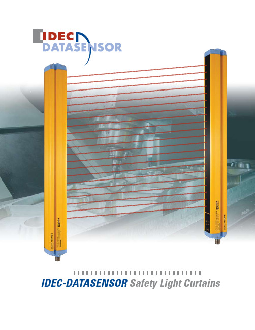
IDEC-DATASENSOR Safety Light CurtainsType 2 SG2 Series (Basic & Extended Models)Hand ProtectionPresence ProtectionIntegrated light curtain for Hand Protection or • Presence ControlOperating distance up to 19m• Controlled heights from 150 to 1800mm • Compact 32 x 37mm profile• Sturdy profile and rotating brackets• Test/Restart, Auto/Manual Restart, EDM, Anti-interference • User interface with display • Alignment function• The SG2 Type 2 series offers two models, the SG2 basic and the SG2 extended. Available functions include Test/Restart, EDM and Anti-interference. With very fast response times, the SG2 series can be installed right next to a hazardous area improving productivity. The ro-tating mounting brackets make installation and the alignment of the emitting and receiving units easy, even at long distances and in applica-tions that use mirrors.Type 4 SG4 SeriesFinger ProtectionHand ProtectionIntegrated light curtain for Finger Protection or • Hand ProtectionOperating distance up to 6m for Finger Protection series • & 19m for Hand Protection seriesControlled heights from 150 to 1800mm • Compact 32 x 37mm profile• Sturdy profile and rotating brackets • Test/Restart, Auto/Manual Restart, EDM • User interface with display • Alignment function• With mounting brackets that rotate, no connection necessary between emitter and receiver, and configuration that can be accomplished with-out external control units or supplementary cables, the SG4 Type 4 light curtains are one of the best available on the market today. In addition, the light curtains can be aligned using the 7 segment display on eitherthe emitter or receiver.Safety Light CurtainsSG2 SeriesSituation Solution Situation Solution Robotic ManufacturingSituation : Protect operator from being hit or crushed by a robotic arm’s movement.Solution Operating Point Protection on a Drilling Machine: An operator positions a part before machining and removes Paper Cutting MachinesThese machines typically cut paper to a specific size for : Protect operator from either being pinned between the top The SG safety light curtain family provides solutions for automation where access to hazardous areas must be controlled. In particular, safety curtains can be used to stop machine movement in the following industries.Automated manufacturing• Packaging, material handling & storage machines • Textile, woodworking and ceramic• Automatic and semi-automatic assembling lines • Automatic warehouse & inventory systems• Applications800-262-IDEC4W max (without load)*If a longer cable is needed, please verify that the capacitive load specifications are followed.Presence Control series.Hand30mmPresence50mm90mmFinger14mmHand30mmenter the Controlled Height code. See table on the right.Part NumbersControl series.AccessoriesM12 Unshielded Axial Connector Cable, UL 2464Used ForL L Ø169M2 nº3 x 2L L Ø16M2 nº3 x 2M2 nº3 x 29Ø1636.932.3M2 nº3 x 2Ø1636.932.3M2 nº3 x 250.514L LL L Ø16ø16OSSD1 OSSD2+24 V DC NOTEST/RESET12340 V+24 V DC Not Used Not Used0 V 1243 Manual RESTART - RESET/RESTART function+24 V DCRESET/RESTART0 VOSSD1 EDMEDMACTIVATION OSSD2 +24 V DC+24 V DCSEL. MAN / AUTO RESTART NONC external contact +24 V DCsee tablebelow 0 V TEST+24 V DCNODimension TableModel L 1 L 2 150* 233.3 153.3 300 383.2 303.2Indicators & SettingsSG4 and SG2 light curtains are equipped with an Alignment system that shows alignment status on a visual display, making configuration quick and easy. Alignment level and any change in environment conditions (presence of dust, light disturbance, etc.) are monitored during normal operating mode. The display also gives diagnostic messages to ensure accurate and correct functioning.Emitter (Tx)Receiver (Rx)Emitter (Tx)Receiver (Rx)800-262-IDECMounting Brackets Dimensions (mm)Rotating Mounting Bracket 1 (ST-K4ROT)Angled Mounting Bracket 2 (ST-KSTD)39.63031. Supplied with the SG2 extended models only.ø6.6ø6.63R2.7R2.718.517.525.637.834.530.76618.518.517.82. Supplied with SG2 standard models and all SG4 models.Anti-vibration Support Brackets (ST-K4AV/ST-K6AV)Mounting Bracket with Light Curtain (mm)BA12.95CL *L 1/SafetySafety Controllers - FS1A SafetyOneConsolidate safety relays to just one safety controller usingthe IDEC SafetyOne FS1A series safety controller.No programming required•Easy to setup: Select Logic, Wire Devices, Power Up•Replaces up to 6 safety relay modules•Select logic from 8 pre-programmed circuits•Connect one module with various types of safety inputs•Monitor status of safety I/Os and error codes•/safetyCustom Application AccessoriesIP67/IP69K EnclosureProtective GuardLens ShieldSafety Relay Module (CS-ME) & EDM Control Box (SE-SR2)IDEC Corporation • 1175 Elko Drive • Sunnyvale, CA 94089 • 800-262-IDEC (4332) • Fax: 408-745-5258 • /usa©2009 IDEC Corporation. All Rights Reserved. Catalog No. SG9Y-DS100-0 10/09 7.5KMore Information/SafetyTechnical support:****************800-262-IDEC。
GuardShield Safe 4 安全光幕 说明书

ᴀߎ⠜⠽ফ⠜ᴗֱᡸˈ㒣㔫䶺ܟᇨ㞾ࡼ࣪䆌ৃϡᕫ䚼ߚܼ䚼ࠊᴀߎ⠜⠽ⱘݙᆍDŽ
ᭈᴀݠЁˈ៥Ӏᖙ㽕ⱘഄᮍߎخњ䇈ᯢˈҹਞⶹᙼᅝܼ⊼ᛣџ乍DŽ
䄺ǂਞ
ᷛ䆚ॅ䰽⦃๗ϟৃ㛑ᇐ㟈⟚⚌ˈ䖯㗠䗴៤ҎਬӸѵǃ䋶ѻᤳണ㒣⌢ᤳ༅ⱘ㸠 ЎᚙֵⱘމᙃDŽ
䞡㽕џ乍 ⊼ǂᛣ
ᷛ䆚ᇍ៤ࡳᑨ⫼⧚㾷ѻક᳝䞡㽕⫼ⱘֵᙃDŽ ᷛ䆚ৃ㛑Ӯᇐ㟈ҎਬӸѵǃ䋶ѻᤳണ㒣⌢ᤳ༅ⱘ㸠ЎᚙֵⱘމᙃDŽ⊼ᛣヺো ৃᐂࡽᙼ⹂ᅮॅ䰽ǃ䙓ॅܡᆇᑊњ㾷ৃ㛑ⱘৢᵰDŽ
䞡㽕џ乍
请妥善保存这些说明,以备将来使用。
专业人员 . . . . . . . . . . . . . . . . . . . . . . . . . . . . . . . . . . . . . . . . . .3
设备的应用范围 . . . . . . . . . . . . . . . . . . . . . . . . . . . . . . . . . . . . . . . . . . . 3 正确使用 . . . . . . . . . . . . . . . . . . . . . . . . . . . . . . . . . . . . . . . . . . . . . . . . . . . 4 一般保护注意事项和保护措施 . . . . . . . . . . . . . . . . . . . . . . . . . . . . 4
䗝ᢽᅝ㺙GuardShield Safe 4 ᅝܼܝᐩПࠡˈ䇋ࡵᖙ䯙䇏⧚㾷ϟ߫㽕∖DŽGuardShield ᅝܼܝᐩ᮶ᰃ᪡⚍ᅝܼ㺙㕂ˈজᰃ਼⬠䖥ᅝܼ㺙㕂DŽᅝܼܝᐩ⫼Ѣ辵ᴎẄϞЎҎਬ ᦤկ᪡⚍਼⬠䖥ᅝܼ䰆ᡸDŽ GuardShield Safe 4ᅝܼܝᐩ㋏߫ᰃ䗮⫼ⱘᄬᛳᑨᓣ䆒ˈЏ㽕⫼Ѣֱᡸᴎ఼Ϟᴎ఼䰘 䖥ᎹⱘҎਬDŽ ᅝ㺙GuardShield Safe 4ᅝܼܝᐩᯊˈᖙ乏䙉ᅜ㘨䙺ǃᎲᔧഄⱘ᠔᳝䗖⫼⊩ᕟ⊩㾘DŽ 䲛Џ᳝䋷ӏཹᅝ㺙ǃ᪡㓈ᡸ㺙᳝GuardShield Safe 4ᄬᛳᑨᓣ䆒ⱘѻકᴎ఼DŽ GuardShield Safe 4ᅝܼܝᐩᖙ乏⬅ড়ḐҎਬཹᅝ㺙DŽ GuardShield Safe 4ᅝܼܝᐩЎᄬᛳᑨᓣ䆒ˈ᮴⊩ЎҎਬᦤկ⛁䰆ᡸǃ࣪ᄺ䰆ᡸ亲㸠䚼 ӊ䰆ᡸDŽᅗӀⱘⳂᷛ⫼䗨ᰃᛳᑨऎ㹿։ܹᯊথߎֵোˈذℶᴎ఼ⱘॅ䰽ࡼDŽ GuardShield Safe 4ᅝܼܝᐩা㛑⫼Ѣৃ䱣ᯊ਼ކᳳذݙℶⱘᴎ఼DŽ GuardShield Safe 4ᅝܼܝᐩϡᕫ⫼Ѣ䞛⫼ܼ䕀ᓣ行ড়఼ⱘᴎ఼DŽ GuardShield Safe 4ᅝܼܝᐩⱘᬜᵰপއѢᴎ఼ࠊಲ䏃ⱘᅠᭈᗻDŽ㺙᳝GuardShield Safe 4 ᄬᛳᑨᓣ䆒ⱘᴎ఼ᑨ䞛⫼ᬙ䱰ᅝܼ䆒䅵ⱘࠊಲ䏃DŽ ᑨᅮᯊẔᶹᴎ఼ⱘ辵ذℶᴎᵘˈ⹂ֱ݊ᎹℷᐌDŽফ䰆ᡸⱘᴎ఼ᖙ乏᳝ৠㄝⱘৃ䴴ᗻҹঞ ৠㄝⱘৃ䞡ذℶᯊ䯈DŽ
最新综合版光幕新使用说明书

位置的要求,否则,仍存在发生事故的可能。 3.1.1. 安全距离的计算 ※ 安全距离是指光电保护装置的光幕平面与模具刃口之间的最小距离,其
计算方法应根据压力机的制动方法或参照表3.1.1确定。
mm 850 800 750 700 650 600 550 500 450 400 350 300 250 200 150 100 50
警告: 未能遵守此警告通知可能会导致失败或故障。 警告: 未能遵守此警告通知可能导致人身伤害/或损坏机台。
1.4 使用指南 此操作说明中所描述的产品,仅作为此型号 产品操作说明,不可作为其他型
号或者其他产品的操作。 安装过程中安全开关必须全程使用,严格按照操作说明的步骤和方法进行安装。
1.5 一般安全说明 用户必须遵守安全指示操作说明书和具体国家的安装标准,以及所有现行的
六.使用、检查与保养 6.1 检查与保养···········································································10
一、基本介绍 1.1 功能
此操作的说明手册提供所有的信息,您需要安装和调试,为确保安全运行和 拆卸安全,请必须认真阅读说明书!
GT/GTD M继电器信号接线方式
继电器输出常开/闭点接线方式
RD 12-24VDC BK 0V BN NPN WT PNP BU CP GY CE YL GND
The receiver
接收端
RD 12-24VDC BK 0V BN NPN WT PNP BU CP GY CE YL GND
The transmitter
光束的数目:
SG-BWS-T4-MT系列安全光幕快速使用手册说明书

SG-BWS-T4-MTSERIESSafety control unit with double mutingQUICK GUIDESAFETY INFORMATIONThe following points must be observed for a correct and safe use of thesafety light curtains of the SG-BWS-T4-MT series:The stopping system of the machine must be electrically controlled. This control system must be able to stop the dangerous movement of the machine within the total machine stopping time T as per par. 3.4 of the complete manual inside the CD and during all working cycle phases.The safety system should be installed and connected by a qualified technician in compliance with the instructions specified in this manual and industry rules.The photocells must be securely installed in a particular position so that access to the dangerous zone is not possible without the interruption of the beams (see 3.3 “General information on sensors positioning” of the complete manual inside the CD). The personnel operating in the dangerous area must be well trained and must have adequate knowledge of all the operating procedures of the safety control unit.The START and TEST buttons must be located outside the protected area because the operator must check the protected area during all Test and Reset operations.Please carefully read the instructions for the correct functioning before powering the SG-BWS-T4-MT.Precautions to be observed for the choice and installation of the deviceMake sure that the protection level assured by the SG-BWS-T4-MT device (Type 4) is compatible with the real danger level of the machine to becontrolled, according to EN 954-1 and EN 13849-1.∙ The outputs (SAFCN) of the ESPE must be used as machine stopping devices and not as commanddevices. The machine must have its own START command. ∙ The dimension of the smallest object to be detected must be larger than the resolution level of theinstalled safety sensors.∙ The ESPE must be installed in a room complying with the technical characteristics indicated in section9 “Technical data” of the complete manual inside the CD. ∙ Do not install the sensors close to strong and/or flashing light sources or close to similar devices. ∙ Strong electromagnetic disturbance might negatively affect device operation. Should this be the casecontact Datalogic Automation Technical Service. ∙ The operating distance of the safety sensors can be reduced in presence of smog, fog or airbornedust. ∙ A sudden change in environment temperature, with very low minimum peaks, can generate a smallcondensation layer on the sensors lenses and so jeopardise functioning.∙ Pay special care when positioning the safety photocells so to offer effective protection. The safetysensors should be installed in such a way that the dangerous area can only be entered after detecting the sensitive area. Photocells position is fixed by normative and must respect measures in Tab. 4 of the complete manual inside the CD.The failure to respect the safety distance reducesor cancels ESPE the protection function.For more detailed information about calculation of safety distance,please refer to the complete manual contained in the CD supplied.CONNECTIONSSIGNAL CONTACT CONNECTION FUNCTIONVDC 1 24 Vdc ext. Power START 2 NO contact toward 24VDC Reset Function TEST/RESET 3 NC contact toward 24VDCTest/Reset functionEDM 4 - NC contact of external relay toward 24VDC (with EDM enabled)- NOT CONNECTED (with EDM disabled)EDM Input0 V 2 0 Vdc ext. Power MUTEN A 6 NO contact toward 24VDC Muting enable MUTEN B 7 NO contact toward 24VDC Muting enable DEFLAMP 8 Warning device positive terminal Lamp failure warningMUTA1 9 PNP output of muting sensor A1 Muting input OVRA1 10 Override A1 NO contact toward 24VDC Override input MUTB1 11 PNP output of muting sensor B1 Muting input OVRB1 12 Override B1 NO contact toward 24VDC Override input MUTA2 13 PNP output of muting sensor A2 Muting input OVRA2 14 Override A2 NO contact toward 24VDC Override input MUTB2 15 PNP output of muting sensor B2 Muting input OVRB2 16 Override B2 NO contact toward 24VDC Override input LAMPA- 17 Negative terminal of muting lamp A Muting lamp output LAMPA+ 18 Positive terminal of muting lamp A Muting lamp output SAFNC11 19Relays output NO 230V 1Safety contact SAFNC21 20 Safety contact LAMPB- 21 Negative terminal of muting lamp B Muting lamp output LAMPB+ 22 Positive terminal of muting lamp B Muting lamp output SAFNC12 23Relays output NO 230V 2Safety contact SAFNC22 24 Safety contact RX1 25 PNP output of receiver photocell 1 (black) Photocell Input RX2 26 PNP output of receiver photocell 2 (black) Photocell Input RX3 27 PNP output of receiver photocell 3 (black) Photocell Input RX4 28 PNP output of receiver photocell 4 (black) Photocell Input TX1 29 TEST of emitter photocell 1 (black) Photocell Output TX2 30 TEST of emitter photocell 2 (black) Photocell Output TX3 31 TEST of emitter photocell 3 (black) Photocell Output TX4 32 TEST of emitter photocell 4 (black) Photocell Output 24VRX12 33 24VDC photocell receivers 1 and 2 (brown) Power supply output 0VRX12 34 0VDC photocell receivers 1 and 2 (blue) Power supply output 24VRX34 35 24VDC photocell receivers 3 and 4 (brown) Power supply output 0VRX34 36 0VDC photocell receivers 3 and 4 (blue) Power supply output 24VTX12 37 24VDC photocell emitters 1 and 2 (brown) Power supply output 0VTX12 38 0VDC photocell emitters 1 and 2 (blue) Power supply output 24VTX34 39 24VDC photocell emitters 3 and 4 (brown)Power supply outputSIGNAL CONTACT CONNECTION FUNCTION 0VTX34 40 0VDC photocell emitters 3 and 4 (blue) Power supply output OSSD11 41 OSSD 1 output of light curtain 1 (grey) Safety light curtain input OSSD21 42 OSSD 1 output of light curtain 2 (grey) Safety light curtain input24LRX12 43 24VDC light curtain receivers 1 and 2(brown)Power supply output0LRX12 44 0VDC light curtain receivers 1 and 2 (brown) Power supply output OSSD12 45 OSSD 2 output of light curtain 1 (pink) Safety light curtain input OSSD22 46 OSSD 2 output of light curtain 2 (pink) Safety light curtain input 24LTX12 47 24VDC light curtain emitters 1 and 2 (brown) Power supply output 0LTX12 48 0VDC light curtain emitters 1 and 2 (brown) Power supply outputNO: Normally Open – NC: Normally ClosedMinimum connection (1 photocell, no EDM, automatic RESTART)The control unit terminals layout and the minimum connection to check system operation are shown below.The photocells set power (blue and brown wires) reaches terminals 33-34, 37-38 as specified in the table in the complete manual inside the CD.For the other configuration (for example concerning muting and override) please refer to section 4 in the complete manual inside the CD.SIGNAL CONTACT CONNECTION FUNCTIONext. PowerVdcVDC 1 24TEST/RESET 3 24 Vdc ext. Test function0 V 2 0 Vdc ext. PowerRX1 25 PNP output of receiver photocell 1 (black) Photocell InputTX1 29 TEST of emitter photocell 1 (black) Photocell OutputRX2 26 TX2 (30) Photocell InputRX3 27 TX3 (31) Photocell InputRX4 28 TX4 (32) Photocell InputOSSD11 41 OSSD21 (42) Safety light curtain input OSSD21 42 24LRX12 (43) Safety light curtain input OSSD12 45 OSSD22 (46) Safety light curtain input OSSD22 46 24LTX12 (47) Safety light curtain input24VRX12 33 24VDC power supply RX (brown) Power supply output 0VRX12 34 0VDC power supply RX (blue) Power supply output24VTX12 37 24VDC power supply TX (brown) Power supply output0VTX12 38 0VDC power supply TX (blue) Power supply outputSG-BWS-T4-MT as MPCE (Machine Primary Control Equipment)SG-BWST-T4-MT can be directly used as a Machine Primary Control Equipment (MPCE) since it’s equipped with internal monitored relays which can switch a maximum load of 3,6A at 250V. The proper connections are shown in the next figure.SG-BWS-T4-MT as external safety relays controllerWhen utilizing SG-BWS-T4 for external safety relays control proper connections are shown in the following figure.K1K2SAFCN11 (19)SAFCN21 (20)SAFCN12 (23)SAFCN22 (24)B W S -T 4-M TMain Supply VoltageT o machine powerALIGNMENT SAFETY DEVICESOnce all components are in place and connected, emitters and receivers shall be mutually aligned.In alignment mode, the OSSD safety outputs are open. The alignment mode and relevantprocedure are described here below:∙Cut off control unit power supply.∙Power on the control unit while holding pressed Test button (Test contact open)∙The 7-segment display shows the first device to be aligned (Photocells 1-4, light curtains 5-6)∙∙The control unit will run the initial test routines and display a countdown, the display will then turn off and the control unit will switch to NORMAL OPERATION status ( NORMAL).Now carry out the following inspections:∙The ESPE stays in SAFE mode during photocells and light curtains beam interruption using the suitable “Test Piece”, along the entire protected area.∙Enabling the TEST function, the OSSD outputs should open ( SAFE and the controlled machine stops).∙The response time upon machine STOP (including response time of the ESPE and of the machine) is within the limits defined for the calculation of the safety distance (see section 3 “Installation” of the complete manual inside the CD).∙The safety distance between the dangerous areas and the safety sensors is in accordance with the instructions included in section 3 “Installation” of the complete manual inside the CD.∙Access of a person between sensors and machine dangerous parts is not possible nor is it possible for him/her to stay there.∙Access to the dangerous area of the machine from any unprotected area is not possible.During alignment or normal operation, make sure that the photocells connected to the same or other units do not interfere with each other. Should you find interference, change their position, for instance you could set some emitter sets on the side of the other receivers. In case of interference, the control unit will lock out and display the relevant error code.DIP-SWITCHES CONFIGURATIONAt control unit top part you will find two units made up of 8 Dip-Switches each: SG-BWS-T4-MT safety rating requires installation of two switches for setting up each function, so that the setup defined for the first unit shall be set even for the second unit.The table below is a list of possible settings selectable through the 8 Dip-Switches available.DIP PURPOSE OFF(Default) ON1 ENABLEEDM ENABLED DISABLED2 RESETMODE AUTOMATIC MANUAL3 MUTING TIME-OUT 10 MINUTES INFINITY4 MUTINGDIRECTION T L5 TRIGGEROVERRIDE LEVEL FRONT6 MUTINGSELECTIONVedi tabella seguente7 MUTINGSELECTION8 MUTINGSELECTIONDatalogic Automation supplies the control unit in the “Default” setup (all switches OFF).The Dip-Switches 6-7-8 allow user to couple the single devices to the 2 muting channels available on the SG-BWS-T4-MT.Activating a channel muting involves temporarily suspending the safety function of all devices associated to it. Extreme care is hence required when associating channel to devices: any dangerous settings shall be avoided.DIAGNOSTICS AND SIGNALLINGSG-BWS-T4-MT is equipped with a user interface featuring 3 LEDs and a 7-segment display.LED INDICATIONPOWER Device is powered correctlyNORMAL No danger: safety outputs closedSAFE Danger or fault: safety outputs openThe 7-segment display shows detailed information on control unit current status Normal operation signallingINDICATION STATUS DESCRIPTION TO DO POWERNORMALSAFE NORMALOPERATIONThe Override function is active on channel A, B or both. The muting indicator isflashing.POWERNORMALSAFE NORMALOPERATION One of the two muting lampsis disconnected or faulty(only one muting channel isactive).Change the faulty lamp.It is not necessary torestart.POWER⇨NORMALSAFEInterlockWaiting for the STARTcommand in manual resetmodePush reset controlPOWER/ NORMAL/ SAFE NORMALOPERATION/SAFE The decimal point indicates that the EDM function isactive (see 4.7)POWER NORMALSAFESAFE TEST push-button pressed(contact 3 open)Check TEST push-button connections (see4.9)Failure state signallingINDICATION STATUS DESCRIPTION WHATTODO POWERNORMALSAFEOff Power disconnected or innerfuse blown due to overload.Check power supply. Iferror persists, pleasecontact the TechnicalService.POWER NORMAL SAFEINTERNALDEVICEMONITORINGFAILURELOCKOUTInternal relays contactsmonitoring test has failed.Reset the control unit(see 4.6). If errorpersists, please contactthe Technical Service.POWER NORMAL SAFE INTERNALOSSDFAILURELOCKOUTInternal OSSD test routinehas failed.Reset the control unit(see 4.9). If errorpersists, please contactthe Technical Service.INDICATION STATUS DESCRIPTION TODO POWERNORMALSAFE EDM FAILURELOCKOUT EDM test has failedCheck EDMconnections (see 4.7)or disable EDMfunction (see 4.4) ifyou do not wish to useit.POWERNORMAL SAFEMICRO-PROCESSORFAILURELOCKOUTOne of microprocessor testshas failedDisconnect powersupply and reconnectit. If error persists,please contact theTechnical Service.POWERNORMALSAFE DIPSWITCHES FAILURE LOCKOUTThe Dip-Switches settingconsistency test has failedMake sure that thesettings of the two setsof switches is the same(see 4.4). Reset thecontrol unit (see4.9). If error persists,please contact theTechnical Service.POWERNORMAL SAFE RESTARTFAILURELOCKOUTStart signal time-out tripped.Make sure you hold theStart button depressedfor less than 5s.POWER NORMAL SAFESENSOR FAILURE LOCKOUT Test of indicated safetysensor has failed.- F 1-4: Make surethere is no interferenceacross differentphotocell sets.- F 5-6: Check lightcurtains OSSDconnections (see4.5).POWERNORMAL SAFELAMPFAILURELOCKOUTMuting lamp faulty ordisconnected.Change the faultylamp, then Reset thecontrol unit (see4.9)POWERNORMALSAFE OVERRIDEFAILUREThe Override commandactivation test has failed(push-buttons not pressed atthe same time)Press the Overridepush-buttons at thesame time.DECLARATION OF CONFORMITYWe DATALOGIC AUTOMATION declare under our sole responsibility that these products are conform to the 2006/42/EC and successive amendments.WARRANTYDATALOGIC AUTOMATION warrants its products to be free from defects.DATALOGIC AUTOMATION will repair or replace, free of charge, any product found to be defective during the warranty period of 36 months from the manufacturing date.This warranty does not cover damage or liability deriving from the improper application of Datalogic Automation products. DATALOGIC AUTOMATION srlVia Lavino 265 - 40050 Monte S.Pietro - Bologna – ItalyTel: +39 051 6765611 - Fax: +39 051 6759324 DATALOGIC AUTOMATION cares for the environment: 100% recycled paper.DATALOGIC AUTOMATION reserves the right to make modifications and improvements without prior notification.© 2009 – 2014 Datalogic Automation - ALL RIGHTS RESERVED - Protected to the fullest extent under U.S. and international laws. • Copying, or altering of this document is prohibited without express written consent from Datalogic Automation. Datalogic and the Datalogic logo are registered trademarks of Datalogic S.p.A. in many countries, including the U.S.A. and the E.U.830000502 rev.C。
施耐德XUSL..WC 1 XUSL.. .WH类型2和类型4安全光幕.外壳,快速指南

接线图尺寸WH: 白色BK: 黑色BN: 棕色GN: 绿色YE: 黄色GY: 灰色PK: 粉红色BU: 蓝色RD: 红色VT: 紫色TRmm in.32012.6047018.5062024.4177030.3192036.22107042.13122048.03137053.94152059.84167065.7576029.92106041.73116045.67290440590 740890104011901340149016407301030113011.4217.3223.2329.1335.0440.9446.8552.7658.6664.5728.7440.5544.49XUSL p E A BC (± 3 mm)Dppp 016ppp 031ppp 046ppp 061ppp 076ppp 091ppp 106ppp 121ppp 136ppp 1512B 3B 4B 315465615 7659151065121513651515166575510551155 12.418.3124.2130.1236.0241.9347.8353.7459.6565.5529.7241.5345.47337487637 7879371087123713871537168777710771177 13.2719.1725.0830.9836.8942.848.754.6160.5166.4130.5942.446.34182071.65197077.561790194070.4776.38ppp 166ppp 1811815196571.4677.361837198772.3278.23762.99562.2752.95BDA C Ø = 5,8 mm (max.)Ø = 0.23 in. (max.)461.8126±11.04±0.4R U NT E S TE R R缆线颜色描述OSSD1K1_K2 反馈/重启Configuration_B0 Vdc FEOSSD2WH BU BN GN PK 0 V (加热系统)24 V a / c (加热系统)VTBK GY YE RD WH BU BN GN PK GY YE RD+ 24 Vdc Configuration_A 无加热系统带有加热系统缆线颜色描述+ 24 VdcFE0 V (加热系统)24 V a / c (加热系统)-0 VdcBN BN RD WH WH BU BU YE GY GYGN PK Configuration_0Configuration_1无加热系统带有加热系统BK 0 Vdc +24 Vdc12345FE 0 Vdc+24 Vdc Conf. 0Conf. 1XUSL ppp TBN WH BUGY BK0 Vdc +24 Vdc12345FE 0 Vdc+24 Vdc Conf. 0Conf. 1XUSL ppp TBN WH BUGY BK0 Vdc +24 Vdc12345678FE 0 Vdc+24 Vdc Conf._AK1_K2Feedback_Restart Conf._B OSSD1OSSD2XUSL ppp RBN GNGY WH BUYERD PK 0 Vdc +24 Vdc12345678FE 0 Vdc+24 Vdc Conf._AK1_K2Feedback_RestartConf._B OSSD1OSSD2XUSL ppp RRESTARTBN GN GYWH BUYE RD PK 12345678FE 0 Vdc+24 VdcConf._A K1_K2Feedback_RestartConf._B OSSD1OSSD2XUSL pppRRESTARTK2K10 Vdc +24 VdcBNGNGY WH BUYERDPK 0 Vdc +24 VdcK2K112345678FE 0 Vdc+24 Vdc Conf._AK1_K2Feedback_RestartConf._B OSSD1OSSD2XUSL ppp RBN GN GYWH BUYE RD PK 不遵守这些说明可能会导致人员死亡、严重伤害或设备损坏。
Schneider Electric XUSL4E30H016N 安全光幕说明书

T h e i n f o r m a t i o n p r o v i d e d i n t h i s d o c u m e n t a t i o n c o n t a i n s g e n e r a l d e s c r i p t i o n s a n d /o r t e c h n i c a l c h a r a c t e r i s t i c s o f t h e p e r f o r m a n c e o f t h e p r o d u c t s c o n t a i n e d h e r e i n .T h i s d o c u m e n t a t i o n i s n o t i n t e n d e d a s a s u b s t i t u t e f o r a n d i s n o t t o b e u s e d f o r d e t e r m i n i n g s u i t a b i l i t y o r r e l i a b i l i t y o f t h e s e p r o d u c t s f o r s p e c i f i c u s e r a p p l i c a t i o n s .I t i s t h e d u t y o f a n y s u c h u s e r o r i n t e g r a t o r t o p e r f o r m t h e a p p r o p r i a t e a n d c o m p l e t e r i s k a n a l y s i s , e v a l u a t i o n a n d t e s t i n g o f t h e p r o d u c t s w i t h r e s p e c t t o t h e r e l e v a n t s p e c i f i c a p p l i c a t i o n o r u s e t h e r e o f .N e i t h e r S c h n e i d e r E l e c t r i c I n d u s t r i e s S A S n o r a n y o f i t s a f f i l i a t e s o r s u b s i d i a r i e s s h a l l b e r e s p o n s i b l e o r l i a b l e f o r m i s u s e o f t h e i n f o r m a t i o n c o n t a i n e d h e r e i n .Product data sheetCharacteristicsXUSL4E30H016NXUSL type 4 - For hand protection - Stdsensing range - Hp = 160 mm, R=30mmMainRange of product Preventa Safety detection Product or component typeSafety light curtain type 4Device short name XUSL4EOutput type2 safety outputs OSSD solid-state PNP (integrated arc suppression)Product specific appli-cation For hand protection [R] Resolution 30 mm[Sn] nominal sensing distance0...4 m by cabling 0...12 m by cabling [Hp] Height protected 160 mm Number of beams 8Type of start / restart Automatic ManualExternal Device Moni-toring (EDM)Selected by wiringComplementaryDetection system Transmitter-receiver system Response time 4 msKit composition1 user guide with certificate of conformity on CD-ROM 1 transmitter(s)1 receiver(s)Adjustable mounting bracket(s)[EAA] effective aperture angle +/- 2.5 ° at 3 m EmissionIR LED (λ = 950 nm)[Us] rated supply voltage 24 V DC (+/- 20 %)SupplyPower supply must meet requirements of IEC 60204-1Power supply must meet requirements of IEC 61496-1[Ie] rated operational current 2 ACurrent consumption900 mA with maximum load (receiver)42 mA (transmitter)83 mA no-load (receiver)42 mA no-load (transmitter)Output current limits 0.4 A for safety outputs OSSD Output voltage 24 V Output circuit type DC Voltage drop <= 0.5 VLocal signalling 2 dual colour LEDs (receiver)1 multi-colour LED (transmitter)Electrical connection 1 male connector M12 8 pins (receiver)1 male connector M12 5 pins (transmitter)Function availableLED display of operating modes and faultsMuting through external safety module XPSLCMUT1160Test Marking CEMaterialEnd caps : polypropylene Front panel : polycarbonate Casing : aluminium Housing colourRAL 3000 : redFixing mode By fixing bracketsProduct weight0.4 kgOffer type Standard distanceEnvironmentDirectives89/336/EEC - electromagnetic compatibility2002/96/EC - WEEE directive2002/95/EC - RoHS directive98/37/EEC - machinery89/655/EEC - work equipmentProduct certifications CECULusTÜVSafety level (correctly wired)PL = e conforming to EN/ISO 13849-1Category 4 conforming to EN/ISO 13849-1SILCL 3 conforming to IEC 62061SIL 3 conforming to IEC 61508Type 4 conforming to IEC 61496-1Optical characteristic Resistance to light disturbance conforming to EN/IEC 61496-2 Mission time20 yrSafety reliability data PFHd = 7.8E-9 1/h conforming to IEC 61508Ambient air temperature for operation-10...55 °C14...131 °FAmbient air temperature for storage-25...70 °C-13...158 °FRelative humidity<= 95 % without condensationIP degree of protection IP67IP65Shock resistance10 gn for 16 ms conforming to IEC 61496-1Vibration resistance0.35 +/- 0.05 mm (f = 10...55 Hz) conforming to IEC 61496-1Offer SustainabilitySustainable offer status Green Premium productRoHS (date code: YYWW)Compliant - since 1425 -Schneider Electric declaration of conformityREACh Reference not containing SVHC above the thresholdProduct environmental profile Available Download Product EnvironmentalProduct end of life instructions Available Download End Of Life ManualContractual warrantyPeriod18 monthsDimensions Drawings DimensionsBrackets DimensionsMounting and Clearance Mounting and Clearance(1)Insert(2)Bracket(3)Washer(4)Spring washer(5)NutConnections and SchemaWiring DiagramsTransmitter Connections(1)+24 Vdc(2)Configuration_0(3)0 Vdc(4)Configuration_1(5)FEReceiver Connections(1)OSSD1(2)+ 24 V(3)OSSD2(4)Configuration_A(5)K1_K2 Feeback/Restart(6)Configuration_B(7)0 Vdc(8)FEReceiver Configurations and Operating ModesAutomatic Start/RestartWithout External Device Monitoring (EDM) feedback loopWith External Device Monitoring (EDM) feedback loopManual Start/RestartWithout External Device Monitoring (EDM) feedback loop(1)RestartWith External Device Monitoring (EDM) feedback loop(1)RestartConnection SchematicsStandalone ApplicationXUSL4E light curtains are conforming to Type 4 (IEC 61496-1), SIL3 (IEC 61508) - SILCL3 (IEC 62061) and PLd- Cat.4 (EN ISO 13849-1:2008)Example of wiring diagram with manual start, external device monitoring and low range(1)Power supply(2)XUSL Receiver(3)XUSL transmitter(4)Low range(5)StartThe contactors K1/K2 must have :*Normally closed mirror contact, according to IEC 60947-4-1 for power contactors*Linked contacts (or force guided contacts), according to IEC 60947-5-1 or EN 50205 for auxiliary contactors or control relays。
莱恩SF系列安全光幕使用说明书

SF系列安全光幕使用说明书◆ 安全光幕的使用关系人身安全,使用前请仔细阅读使用说明书◆ 说明书是指导用户正确安装、使用安全光幕的重要文件,请代理商、经销商、机床厂务必将使用说明书随安全光幕交付用户山东莱恩光电科技股份有限公司SHANDONG LAIEN OPTIC-ELECTRONIC TECHNOLOGY CO.,LTD.感谢您选用“LNTECH(莱恩)”牌安全光幕!本安全光幕主要用于汽车电子产业、包装业等自动化领域,防止工作人员误入危险区域造成的人身伤害,保护人身安全。
本安全光幕仅保护发光器与受光器(SF系列)之间的矩形光幕区域。
如果其安装位置不正确,或不按说明书与相关安全作业条例操作,或被保护设备执行机构故障,都可能使其无法起到保护作用。
因此,安装本光幕之前,请仔细阅读说明书,充分理解有关事项,尤其是说明书中标出的“警告”、“注意”等内容;在使用过程中,请正确理解安全光幕的工作性能,严格按照本说明书所提出的要求,制定相应的安全作业条例。
本说明书内容解释权归山东莱恩光电科技股份有限公司,阅读或使用本说明书时,如有不明之处,请与本公司联系。
禁止事项:禁止擅自复印、转载本使用说明书的部分或全部内容。
关于本使用说明书的内容,将来可能因装置改良等原因而进行修改,恕不另行预告。
本使用说明书虽经精心制作以期万全,但如果您发现有不明之处或异常、错页或缺页等时,烦请您通知最近的本公司办事处。
1)2)3)1 重要资料1.1 概述 (1)1.2 使用说明书的组成 (1)1.3 适用范围 (1)1.4 欧洲指令验证 (1)1.5 欧洲标准验证 (2)1.6 中国标准验证 (2)1.7 术语 (3)1.8 安全须知 (4)2 基本介绍2.1 外形尺寸图 (5)2.2 规格型号 (6)2.3 检测精度与光轴间距的关系 (7)2.4 技术标牌 (8)3 产品描述3.1 技术参数 (9)3.2 特点 (10)3.3 工作示意图 (10)3.4 应用案例 (11)3.5 应用条件 (13)4 功能配置4.1 外部装置监视功能(EDM) (14)4.2 辅助输出功能 (15)4.3 辅助对光功能 (15)4.4 对光强弱指示功能 (16)5 SF系列安全光幕的安装5.1 安全距离的计算 (17)5.2 相邻安装时的注意事项 (19)5.3 有反射物时的正确安装位置 (20)5.4 安装说明 (21)5.5 安装工具 (25)6 SF系列安全光幕部件说明6.1 主体部件说明 (26)6.2 发光器指示灯说明 (27)6.3 受光器指示灯说明 (28)7 接线7.1 SF系列安全光幕I/O接线 (29)7.2SF系列安全光幕与SR4P2A1B24N/P接线 (32)7.3 SF系列安全光幕与SR4P3A1B24接线 (34)7.4 SF系列安全光幕与SR4P2A1B24N/P-M接线 (35)7.5 信号电缆 (37)7.6 接线注意事项 (38)8 SF系列安全光幕的调试8.1 安全光幕的调试 (39)8.2 试运行 (39)9 使用、检查、保养9.1 使用注意事项 (40)9.2 检查与保养 (40)10 简单故障检修10.1 安全光幕故障判别 (41)11 配货信息11.1 配货 (42)1.重要资料1.1 概述本说明书包含了关于SF系列产品的说明、操作、安装、电气连接、维护和故障判断等资料。
冲床装置专用安全光幕

冲床装置专用安全光幕随着社会的快速发展,机械加工设备的使用越来越广泛。
冲床作为一种常用的加工设备,在工业生产中扮演着非常重要的角色。
但由于操作不当或设备的故障,冲床在使用过程中会造成很大的伤害或损失。
为了确保使用者的安全和设备的正常运转,冲床装置专用安全光幕被广泛地应用于冲床设备中。
安全光幕的作用安全光幕通常被用于冲床设备的安全保护。
它是由一组发射器和接收器组成的,通过红外线在发射器和接收器之间形成一道薄膜,用于检测并保护人们的安全。
当操作人员不慎挡住光射线时,安全光幕能够及时地感测到,并立刻停止机器设备的运行,保护人员不受到任何伤害。
安全光幕的使用范围安全光幕主要适用于冲床设备上的自动化生产线。
对冲床设备制作过程中高速旋转运动影响危险大的轴、杆、锤头、刀具等部件,需要配置安全光幕。
同时,对于普通的冲床设备,也应该考虑在必要的部位配置安全光幕。
安全光幕的种类目前市面上主流的安全光幕种类有两种:单光束安全光幕及双光束安全光幕。
单光束安全光幕单光束安全光幕是安全光幕技术的最早期代之一。
它由一根发射端和一根接收端组成,发射端向接收端发射红外光束,在一定范围内对运动物体进行不间断的感测与监控。
在使用中,由于光束的粗细和发射端和接收端的距离等因素的影响,会出现误打误撞的情况,从而影响了使用效果。
为了解决这一问题,后来出现了双光束安全光幕。
双光束安全光幕双光束安全光幕不同于单光束安全光幕的是,它采用了两根红外发射器,两根对应的红外接收器,并且每个接收器的接收距离都非常短,这样可以排除误判的情况。
如果在使用过程中,某一组光幕中任何一根发射器或接收器与其对应的光束发生偏差或损坏,双光束安全光幕就会停止正常的工作,停止设备运行,确保了操作人员和设备的安全。
安全光幕的安装方法安装安全光幕需要注意以下几个方面:安全距离安全光幕的遮挡距离有许多的标准和规范。
操作人员需要按照具体的操作条件和使用规范选择安全距离。
如果难以判断或没有明确的使用规范,可以根据设备的最高运转速度及装置的动力和冲击力等因素进行大致的计算。
说明光幕的应用和工作原理

说明光幕的应用和工作原理应用场景光幕是一种常用的安全设备,广泛应用于工业自动化、机械设备、电梯、物流等领域,用于确保人员和设备的安全。
下面介绍几个主要的应用场景。
工业自动化在工业生产过程中,光幕可以用来检测和防止工人进入危险区域。
通过在机器或设备的周围放置光幕,当工人接近危险区域时,光幕会发出信号,停止设备的运行,从而保护工人的安全。
电梯安全光幕在电梯中也有重要的应用。
电梯光幕系统可以监测电梯门口是否有人或物体,以避免电梯门夹人或夹物体。
当光幕探测到有人或物体进入电梯门口时,电梯门会自动停止关闭,保护乘客的安全。
物流行业在物流行业中,光幕被广泛应用于包装和处理自动化设备。
通过设置光幕,可以确保机器只在没有人员或其他物体靠近的情况下工作,以防止意外事故和损坏货物。
工作原理光幕是基于红外线技术工作的,其原理如下:1.发射器和接收器光幕由两个主要部分组成:发射器和接收器。
发射器通过发射红外线光束,而接收器则负责接收光束,并根据接收到的信号来确定目标是否被遮挡。
2.红外光束发射器会发射一束红外光束,这个光束被设置成平行的。
光束会以相对较高的频率传输,通常是以每秒数万次的速度进行。
3.反射和遮挡当光束到达接收器时,接收器会检测光束的强度。
如果光束被目标物遮挡,接收器接收到的光强度会下降。
通过检测光强度的变化,光幕系统可以确定是否有目标物体进入光幕范围。
4.响应和报警当光幕系统检测到目标物体进入光幕范围时,它会立即发送信号给控制系统,并采取相应的措施。
这可能包括停止设备运行、报警、或其他必要的操作,以保护人员和设备的安全。
优点和局限性光幕作为一种安全设备,具有许多优点,但也存在一些局限性。
优点•高灵敏度:光幕能够精确地检测到目标物体的存在,并在短时间内做出响应。
•快速反应:光幕系统可以立即响应并采取措施,以防止事故的发生。
•可靠性高:光幕系统采用红外线技术,具有较高的稳定性和可靠性。
•安装简便:光幕可以灵活安装在不同的位置,以适应不同的应用场景。
安全光幕使用过程中要注意哪些问题?
安全光幕使用过程中要注意哪些问题?
我们在购买了安全光幕后,在日常的使用中,我们的安全光幕还是要注意一些问题的,下面,小编就例举一下安全光幕使用过程中要注意的问题。
1.工作前进行检查
安全光幕传感器(使用前) 开机进入工作状态前的检查:为了人身和设备的安全,必须进行安全检测,严格按照步骤操作,并做好记录,登记在册。
2.安全光栅检测方法
在安全光幕传感器开机进入工作状态后,使用直径为最小检测体尺寸的测试棒(或同等直径的不透明物体,垂直侵入保护区域,分别按顺时针和逆时针方向在保护区域内做平移运动,此时光幕传感器应一直有红色指示灯被点亮,受控设备无法工作。
3.安全光幕判断方法
a.当保护区域内无侵入物体时,传感器的接收器处于受光状态,此时接收器的通讯指示灯(红灯)应熄灭,发射指示灯(黄灯)点亮,这时按下被保护设备的工作开关,设备可正常运转
b.当有物体(不小于最小可检测体或者分辨率)侵入保护区域时,接收器的红色指示灯将被点亮(可能是接收器处于遮光状态,也可能是光通讯被遮断),此时被保护设备受控,处于强制停顿状态。
c.当侵入物体撤出保护区域后,光幕传感器将返回a状态,设备将继续工作
4.安全光幕传感器清洁度特别注意的是镜面。
5.工作前先检查光电是否有坏。
6.关团后检查线路是否有异常。
7.当安全光幕无法正常运行时,请和安全光栅厂家联系,切勿私自进行安全光栅的拆除,以免造成厂家没法进行正常保修。
欧姆龙 F3SJ-A P系列 安全光幕 说明书
ḋ 㓪 SCHG-C-718BF3SJ-A P ㋏ (Ver.2) 㓪 SCHG-C-718B F3SJ-A P ㋏ (Ver.2)㓪 ˖SCHG-C-718B200607S01ㅔҟ䇶 䌁фF3SJ㋏ ˄ҹ ㅔ⿄ĀF3SJā˅DŽ䖭 ㅔ ҟ㒡F3SJⱘ⫼⊩DŽՓ⫼F3SJ 㽕⊼ ҹϟ ⚍ ˖g 䆕F3SJⱘ 㗙 ❳ 㺙ⱘ ⱘĀ䋷ӏҎāDŽg ЁՓ⫼ⱘ 䆡Ā䋷ӏҎā 䌘䋼ⱘǃ㒣䖛 ⱘǃ 䋳䋷 䆕ⱘ䆒䅵ǃ 㺙ǃ ǃ㓈 㕂ⱘ 䖛ⱘĀ āⱘҎ DŽg 䆒 ḍ ⱘ 㺙⦃ ǃ 㛑 㛑 ℷ⹂Փ⫼F3SJDŽg䋷ӏҎ 㺙 䖯㸠 ⱘ亢䰽䆘Ԅ 䗖 Ѣ ѻ DŽg 㺙 ѻ ˈ䅸ⳳ䯙䇏 ˈ⧚㾷 ⫼ 䗄DŽ㕂 ӏԩ䳔㽕ⱘ 䛑㛑⫼ 䯙ⱘ DŽiF3SJ-A 用户手册简介简介C 1.单独使用F3SJ-A 传感器将不能获得日本劳动卫生法的第44-2条的类型批准。
必须将它用在一个系统中。
因此,在日本把F3SJ-A 当作这个法律的第42条所描述的“压力或剪切机器的安全系统”使用时,系统必须获得类型批准。
2.根据欧盟(EU )的机械指令索引附件IV ,B ,安全部件,第1条,F3SJ-A 是光电保护设备(ESPE )。
3.F3SJ-A 符合下列法规和标准(1)EU 法规机械指令 98/37/ECEMC 指令 89/336/EEC(2)欧洲标准EN61496-1(类型4 ESPE ),prEN61496-2(类型4 AOPD ),EN61508-1~-7(SIL3)(3)国际标准IEC61496-1(类型4 ESPE ),IEC61496-2(类型4 AOPD ),IEC61508-1~-7(SIL3)(4)JIS 标准JIS B 9704-1(类型4 ESPE ),JIS B 9704-2(类型4 AOPD )(5)北美标准UL61496-1(类型4 ESPE ), UL61496-2(类型4 AOPD ), UL508, UL1998, CAN/CSA 22.2 No.14, CAN/CSA 22.2 No.0.84.F3SJ-A 从EU 公认的认证机构TÜV-PS 取得了以下的认证:•EU 类型检验符合EU 机械指令,类型4 ESPE (EN61496-1),类型4 AOPD (prEN61496-2)•EMC 证书(测试的电源:OMRON S82K )..•TUV-PS 类型批准,类型4 ESPE (EN61496-1),类型4 AOPD (prEN61496-2),SIL1,2,3(EN61508-1~-7),应用:EN954-1 分类B ,1,2,3,45.F3SJ-A 计划将从第三方评估机构UL 取得符合美国和加拿大安全标准的UL 证书。
施耐德XULE2.... XUSL4E...类型2和类型4安全光幕、快速入门说明书

/XU0002引脚号12345+24 VdcConfiguration_0 或 Master/Slave_A 0 VdcConfiguration_1 或 Master/Slave_B FE描述M12, 5-Pin45321T36758421M12,8 针单对模型(XUSL4E 或 XUSL2E)或主站模型主连接器 (XUSL4E)0 Vdc FEOSSD1+24 Vdc OSSD2K1_K2 反馈/重启Configuration_B12345678Configuration_A 引脚号描述45321引脚号描述12345M12,5 针主站模型辅助连接器或从站模型 (XUSL4E)Master/Slave_A +24 Vdc 0 VdcFEMaster/Slave_BRR接线图手动启动/重启,带 EDM 反馈环路手动启动/重启,不带 EDM 反馈环路发射器 - 短检测距离连接发射器 - 长检测距离连接0 Vdc +24 Vdc0 Vdc +24 Vdc0 Vdc +24 Vdc自动启动/重启,不带 EDM 反馈环路12345678FE 0 Vdc+24 Vdc Conf._AK1_K2Feedback_Restart Conf._B OSSD1OSSD2XUSL ppp R0 Vdc +24 VdcK2K1自动启动/重启,带 EDM 反馈环路12345678FE 0 Vdc+24 Vdc Conf._AK1_K2Feedback_RestartConf._B OSSD1OSSD2XUSL ppp R0 Vdc +24 Vdc12345678FE 0 Vdc+24 Vdc Conf._AK1_K2Feedback_RestartConf._B OSSD1OSSD2XUSL ppp RRESTART12345678FE 0 Vdc+24 VdcConf._A K1_K2Feedback_RestartConf._B OSSD1OSSD2XUSL pppRRESTARTK2K10 Vdc +24 Vdc不遵守这些说明可能会导致人员死亡、严重伤害或设备损坏。
KSO6M型安全光幕说明书

其安装位置不正确,或不按说明书与相关安全作业条例操作,或
设备执行机构故障,都可能使其无法起到保护作用。 因此,安装
本装置之前,请仔细阅读说明书,充分理解有关事项,尤其是说
明书中标出的“警告”、“注意”等内容;在使用过程中,请正确理
解安全光幕的工作性能, 严格按照本说明书与安全光幕相关安
全作业条例操作。
42
615 630 1000 1025 1040 1500 1435 1450 1750
44 430 445 750 645 660 1000 1075 1090 1500 1505 1520 1750
46
675 690 1000 1125 1140 1500 1575 1590 2000
48 470 485 750 705 720 1000 1175 1190 1500 1645 1660 2000
! 注意
这是关键信息提示标签。 标签内容很重要。 作业人员必须了解 并按信息要求严格执行, 避免可能出现的法律纠纷和产品损 坏。
请注意:电气设备必须由合格的专业人员进行安装, 操作,服务和维护。
-2-
第1部分安全需求
! 警告
KS06M 型安全光幕必须由专业人士进行安装和维护保养。 安装使用KS06M 型安全光幕前,请仔细阅读本说明书,正确 理解并严格按照本说明书相关要求作业。 不按照本说明书执行可能造成人员伤害或设备损坏!
(4 ) GB4584
2007的要求,具有安全性
高、外观纤小、探测无效区小、检测精度高(最高14mm,可用于保
护手指)等特点,适用于自动化领域及机械加工现场。
KS06M型安全光幕可对3m、6m、9m等不同距离的危险区域
提供防护,用户可根据实际台面宽度选择合适的光幕型号。
西门子安全光幕 sf2 系列说明书

•Integrated light curtains for HAND PROTECTION •30 mm resolution and operating distance up to 15 m •31 x 32 mm compact profile•Versions with automatic or manual RESTARTThe SAFEasy TM light curtains of the SF2series, according to the IEC 61496-1 and IEC 61496-2 standards, are very suitable for hand protection of operators exposed to risks.Different models are available with ten st andard heights ranging from 150 to 1500mm, 30 mm resolution and an operating distance reaching 15 m.The emitter and receiver unit s are optically synchronised and cont ain all the control circuits, test input and two safety outputs inside the housing.The connection with the machine stopping circuit s are guaranteed by unshielded M12 4-pole connectors for the emitter and M12 5-pole connectors for the receiver.The SAFEasy TM light curtains of the SF2series have also integrated the test function, automatically activated every 0.5 seconds, without stopping the machine's working cycle.A wide range of industrial applications, requiring operator safety , can be solved by the SAFEasy TM light curtains, thanks to the extremely compact dimensions (31x32mm), easy installation and excellent performances.SF2-HAND SERIESSAFEasy ™TYPE 2 LIGHT CURTAINSS A F E T Y D E V I C E SL 323153.314.9M12x1VERSIONS L1 L2SF2-30-015227147SF2-30-030374294SF2-30-045521441SF2-30-060668588SF2-30-075815735SF2-30-090962882SF2-30-10511091029SF2-30-12012561176SF2-30-135********SF2-30-150155014701L2mm The LED p anel present on theextremely compact receiving unitguarantees an easy and immediateindication of the operating st atusof the safety light curtain.These LED indicators supply alsoinformation relative to thedevice’s effective alignment anddiagnostics.DIMENSIONSRECEIVER (RX)EMITTER (TX)CONNECTIONSOSSD1 PNPOSSD2 PNP0 V+24 Vdc+24 Vdc1= brown= +24 Vdc2= white= OSSD13= blue= 0V4= black= OSSD25=grey= TEST(refer to note) **= automatic RESTART (X version) TEST/RESET function= manual RESTART (Y version) TEST/RESTART/RESET function+24 VdcNOT USEDNOT USED0 V1= brown= +24 Vdc2= white= NOT USED3= blue= 0V4= black= NOT USEDPower supply (Vdd):24 Vdc ± 20% (SELV /PELV)Consumption: 50 mAmax. / 1 W (emitter)90 mA max. / 2.5 W (receiver without load)Light emission: infrared LED 880 nm Optic diameter:Ø 18 mmNumber of controlled beams: refer to table 1Optic interaxis: 18.4 mm Resolution:30 mmControlled height: refer to table 2Operating distance: 0.2 ... 15 mReceiver inputs:external switches for Test and Restart Receiver indicators: 2 yellow ALIGNMENT LEDs red BREAK LED green SAFE LEDEmitter indicators: yellow WORKING UNIT CHECK LED green POWER ON LED Output type:2 PNPshort-circuit protection:max.1.4 A at 55°Cmin. 1.2 A at 0 °COutput current (for all loads): 500 mA max. per output Output voltage ON min.:Vdd - 1 V Output voltage OFF max.:0.2 V Leakage current:0.65 mA Capacitive load (pure):100 nF max.Resistive load (pure):60 Ωmin.Response time:refer to table 3Receiver connection: M12 5-pole connector Emitter connection: M12 4-pole connector Safety category:type 2Electrical protection: class 1Mechanical protection: IP65 (EN 60529)IP67(connector part)Housing material:painted aluminium Cap end material:PBT Lens material:PMMACable length:50 m max * (at 100nF capacitive load and Vdd=24V)M12 conductors (according to EN 50044, EN 60947-5-2) poles Ø = 32x0.1mm, external Ø = 0.5mm Weight:1 Kg. max. / m of total height Operating temperature:0 ...+55 °C Storage temperature: -25 ... +70 °CReference standards:EN 954-1, IEC 61496-1, IEC 61496-2* = if a longer cable has to be used, please verify that the same specifications are respectedTECHNICAL DATATABLESModelSF2SF2 height 1508SF2 height 30016SF2 height 450 24SF2 height 60032SF2 height 75040SF2 height 900 48SF2 height 1050 56SF2 height 120064SF2 height 1350 72SF2 height 150080Table 2: CONTROLLED HEIGHT (mm)ModelSF2SF2 height 150187SF2 height 300334SF2 height 450 481SF2 height 600628SF2 height 750775SF2 height 900 922SF2 height 1050 1069SF2 height 12001216SF2 height 1350 1363SF2 height 1500 1510Table 1: NUMBER OF CONTROLLED BEAMSTable 3: RESPONSE TIME (ms)ModelSF2SF2 height 15014SF2 height 30015SF2 height 450 16SF2 height 60017SF2 height 75018SF2 height 900 19SF2 height 1050 20SF2 height 120022SF2 height 1350 23SF2 height 150024II3DDistributed by:。
abb jokab safety focus ii 安全光幕 栅栏 手册说明书
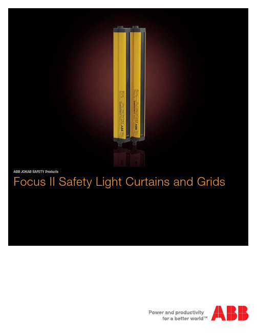
ABB JOKAB SAFETY ProductsFocus II Safety Light Curtains and Grids2 | ABB JOKAB SAFETY - Focus II Safety Light Curtains and Light GridsMuting with MFII-Tand MFII-L Units Focus II is a new version of our previous Light Grid/Light Curtain Focus. Features such as muting and override are standard in all Focus II Light Curtains and Light Grids. For Light Curtains, blank-ing and break functions are also standard. The optical sensors on Focus II also have variable channel frequencies. The Focus II units are Light Curtains/Grids with safety functions intended for applica-tions where it is of great importance to protect persons from a dangerous machine, robot or other automated systems where it is possible to access to a dangerous area.Focus II creates a protection field with infrared beams. If any beam is interrupted the safety mechanism is triggered and the danger-ous machine is stopped. Focus II fulfills the requirements for non-contact safety equipment type 4 (Focus II series) according to the international regulation standard EN 61496-1.Units are available with safety heights between 150 and 2400 mm. All electronic control and monitoring functions are included in the Light Curtain profiles. External connection is made via a M12 con-nection at the end of the profile. Synchronization between trans-mitter and receiver is achieved optically. No electrical connection between the units is required. Control and monitoring of the beam transmission is carried out by two micro-processors which also give information on the status and alignment of the Light Curtain via several LEDs.Muting and Override included in all Focus IIThe “Muting” and “Override” functions are available on all Focus II Light Grids/Curtains and is enabled directly when an indication lamp is connected. Muting implies that one or more segments or the whole Light Curtain can be bypassed during in and out pas-sage of material.In the Focus II with Muting there is also an Override function which makes it possible to bypass the Light Grid/Curtain—i.e. activate the outputs if a machine start is necessary even if one or more Light Beams are interrupted. This is the case when the muting function is chosen and the A and B inputs are activated. If, for example, during the muting operation a loading pallet has stopped inside the safety field after a voltage loss, the override function is used to enable the pallet to be driven clear.Floating Blanking or Fixed BlankingThe “Floating blanking or Fixed blanking” functions are available on all Focus II Light Curtains and is enabled directly via the internal dipswitches. Floating blanking makes it possible to ‘disconnect’ a defined number of beams from the safety field. The object is then free to move in the safety field without the safety function being triggered. During “fixed blanking” the object is not able to move in the safety field. The other beams are active with normal resolution.ApplicationsOptical protection in an opening or around a risk area for:■ Mechanical and hydraulic power presses ■ Molding presses■ Stamping, riveting and eyelet operations ■ Automated machinery ■ Robotic cells ■ Conveyors■ Material handling equipment ■ Printing presses ■ Welding equipment ■ Machining centers ■ Packaging machineryFeatures■ Type 4 according toEN 61496■ Flexible assembly ■ LED indication■ High protection class (IP65)■ Range 3 to 40 m ■ Time reset■ Floating/fixed blanking ■ Muting■ Single/double break function (PSDI)■ External device monitoring (EDM)■ Available with different resolutions ■ U p to PL e according to EN 954-1/EN ISO 13849-1ApprovalsFocus II Safety Light Curtains and Light GridsABB JOKAB SAFETY - Focus II Safety Light Curtains and Light Grids | 3Focus II Light CurtainStandard■ Muting (bypassing) partly or completely ■ Supervised output for muting lamp ■ Override■ Manually supervised or automatic reset ■ Time-reset■ Fixed or floating blanking ■ Single/double break ■ EDMSafety outputs OSSD1 and OSSD2Focus II has two PNP outputs—OSSD1 and OSSD2. If the load to be switched is alternating current or requires a higher cur-rent than 500 mA then one should use a safety interface, e.g. E1T, Pluto PLC or the FRM-1 unit (converts the outputs to relay contacts) from ABB JOKAB SAFETY. The FMC-Tina and Tina 10A/10B/10C converts the outputs to a dynamic signal for con-nection to Pluto or Vital. Pluto can also work directly with the OSSD-outputs.Single/Double Break Function (PSDI)With the Single Break function the Light Curtain allows operationafter entry and withdrawal out of the curtain. Similarly, the Double Break function allows operation after entry and withdrawal twice.External Device Monitoring (EDM)In all Light Grids and Light Curtains an EDM function is available which allows Focus II to test if the external control element re-sponds correctly. A test channel is connected through the respec-tive contactor, in order to detect any faults and thereby prevent a reset.Focus II Light GridStandard■ Muting (bypassing) of one, two, three or four beams ■ Supervised output for muting lamp ■ Override■ Manually supervised or automatic reset ■ Time-reset ■ EDMOption■ Light Grids for tough environments with parallel beams of lightfor improved reliability.ResetOn every Focus II there are inputs for reset and other functions—Reset, Alignment and Override (bypassing is only possible when muting is used.) The reset option is chosen through dual switches in the Focus II receiver. At delivery, Focus II is set to automatic reset.■ Automatic reset – When the light field is free the outputs areclosed directly. (Setting when delivered).■ M anual reset – Focus II gives a ready signal when the light fieldis free and the reset button has been actuated.■ T ime reset – During manual reset. To reset the Focus II a pre-reset button must first be actuated and after wards within 8 seconds a reset button outside the risk area must be actuated.Note: For further technical information, please reference the Focus IIoperating manual.Built-in muting for Focus II is available in three ways:■Pre-made muting units MF-T and MF-L, which have integralphotocells.■ Connection of muting sensors via a FMC.■ Separate connection of muting sensors (Mute R) directly to theFocus II receiver unit.Muting-lampIt is possible to connect the muting-lamp via a FMC. Duringbypassing the muting-lamp is lit. Bypassing is only possible if themuting-lamp is functioning or a resistor of 220 Ohm is used in itsplace.MF-T and MF-L are muting units with integrated photocells builtinto a aluminum profile. They work with all Focus II Light Curtainand Light Grids. No additional sensors are required because themuting units contain the required components. MF-T/MF-L is con-nected between the Focus II and the supervising unit (e.g safetyrelay, safety PLC). The cable between the Focus II and MF-T/MF-Lis included with the muting unit.Muting with MF-T and MF-L unitsMF-TThe muting unit MF-T consist of a transmitter unit and a receiverunit with four photocells A1, B1, B2 and A2. A1 and A2 are con-nected in parallell and B1 and B2 connected in parallell. In this waythe unit is configured for installations where material is transportedinto and/or out of a hazardous area.MF-LThe muting unit MF-L consist of a transmitter unit and a receiverunit with two photocells A1 and B1. The A1 and B1 sensor areactuated before the material is transported through the LightCurtain and Light Grids. The Light Grid is an active part in uphold-ing the muting function once A1 and B1 have been passed by thematerial. The Light Curtain and Light Grids are being bypassed justas long as the material exiting. Unit MF-L is primarily intended formaterial transport out of a hazardous area.MF-T ReflexThe muting unit MF-T Reflex consist of a transmitter/receiver sideand a reflector unit. The active side contains four transmitters/receivers photocells. The MF-T Reflex works as the MF-T with alimited range (6m). These units, together with a Light Grid with oneactive and one passive side provides a good solution where electri-cal connections are only necessary on one side!MF-L ReflexThe muting unit MF-L Reflex consist of a transmitter/receiver unitand a reflector unit. The active side contains two transmitters/receivers photocells. The MF-L Reflex works as the MF-L with alimited range (6m). These units, together with a Light Grid with oneactive and one passive side provides a good solution where electri-cal connections are only necessary on one side!M12 connection betweenFocus II and MF-T ReflexMuting (bypassing)Focus II muting types■ T-muting. Four NO muting sensors are used in two pairs (ORfunction), allowing bi-directional transport of material. Maximummuting time is 600 s. Muting A and Muting B need an activationtime difference of 30 ms.■ L-muting. Two NO muting sensors works together with the lightprotection, allowing transport out from the hazardous area.Maximum muting time is 600 s. Muting A and Muting B need aactivation time difference of 30 ms.■ X-muting. One NO and one NC muting sensor is like a crossthrough the light protection, allowing bi-directional transport ofmaterial. An alternative X-muting (only on Focus Light beams)with 2 NO muting sensor is also possible, but then with thecondition of a 30 ms activation time difference on the mutingsensors. Both solutions gives an infinite muting time.4 | ABB JOKAB SAFETY - Focus II Safety Light Curtains and Light GridsABB JOKAB SAFETY - Focus II Safety Light Curtains and Light Grids | 5Various FMC, FMI, FRM- versions and Tina unitsThe Tina-versions have dynamic safety outputs for Vital/Pluto.Muting accessories FMC and FMI unitsModelDescriptionFMC-1(2)with connectors for muting sensors (A+B),reset, power off and muting lamp (R) and muting lamp (M).FMI-1A with muting lamp only.FMI-1B with reset, power off and muting lamp.FMI-1C with reset and power off.FMI-1Dwith reset, power off and internal resistor for the muting lamp.FMI-1Eas pre reset connected to connector A (A2) on FMC-1(2) (Tina).FMI-1G with reset, and internal resistor for the muting lamp.FMC-1(2) Tina same as FMC-1(2) but connected to Vital or Pluto.Tina 10Aadaptor unit for connecting Focus II to Vital or Pluto.Tina 10B simplified FMC-1(2) Tina including only theconnector (R).Tina 10C simplified FMC-1(2) Tina including only powersupply on con.no.3.FRM-1Atranslates the two OSSD outputs to relay outputs (and power supply).JS SP-1protection plug for not used connectors.JS AP-1adaptor for FMC units to use instead ofFMI-1B or -1D on the (R) connector includingmuting resistor.Applications:■ FMC: Muting connection box ■ FMI: Muting IndicatorFeatures:■ Small■ Easy to connect6 | ABB JOKAB SAFETY - Focus II Safety Light Curtains and Light GridsMuting Lamp Protect CablesTest/Reset ButtonsCable to Lamp Supply CableMuting Cable FR Cable FT CableConnection of Focus II and Muting Components with FMC1 and FMI1Connection of Light Curtain with connection block FMC 1, text/reset button 1 and switch for supply voltage placed in or by the control cabinet. Connection of Light Curtain with connection block FMC1. The FMI reset unit must be placed out of reach from the risk area.Focus II Modular Muting CapabilitiesThe Focus II Safety Light Curtain offers the selection of complete muting of the protective field during the in and out passage of material. Through dipswitch settings in the Focus standard ver-sion, it is also capable of muting only specific modules within the protective field.The Focus II is capable of muting independent beam module packets or a combination of them (up to 4). For example, a box travels down a conveyor and instead of muting the entire LightCurtain you can mute only modules 1 and 2—which equates to the height of the box—allowing continual protection on the remaining Safety Light Curtain modules.The module size is directly dependent on the Focus II Light Curtain resolution and length.The test/reset button shall be placed so the operator can see the protected area during reset, testing and bypassing, It should not be possible to reach the button from within the risk area.The lamp for indication of muting and bypassing shall be placed so that it can be seen from all directions from where it is possible to access the dangerous area.If photocells are used as muting sensors, the sensor receivers should be assembled on the Light Curtain’s transmitter side to minimize the interference risk.The system is protected against dangerous functions caused by damage on the transmitter cable and/or the receiver cable. How-ever, we recommend that the cables be protected so that physical damage to them can be minimized.Connection of Focus II and Muting Components directly to Control CabinetMuting LampCabinetConnection Unit FMC1Muting PhotocellsPower “off”Test/ResetMuting LampCabinetConnection Unit FMC1Muting PhotocellsResetPower “off”Muting accessories (cont.)FMC and FMI unitsAdjustable mounting brackets - MountThe Focus II adjustable mounting brackets offer over 12 different mounting possibilities with adjustability in vertical height, pivoting, rotating and angleling. The adjustable brackets simplify the instal-lation and set up of Focus II Safety Light Curtains and Grids Applications:■Focus Light Curtains and Light Grids mountingFeatures:■Over 12 different mounting capabilities ■High rotational radiusBrackets technical dataManufacturer ABB JOKAB SAFETY Ordering information visit for ordering information ColorBlack powder coatedABB JOKAB SAFETY - Focus II Safety Light Curtains and Light Grids | 7Focus II Type 4 (FII-4) summary■Standard✦With Tina 10A/10B/10C or FMC_Tina.8 | ABB JOKAB SAFETY - Focus II Safety Light Curtains and Light Grids■Standard✦With Tina 10A/10B/10C or FMC_Tina.ABB JOKAB SAFETY - Focus II Safety Light Curtains and Light Grids | 9Technical dataManufacturer ABB JOKAB SAFETYO rdering information visit for ordering informationSupply voltage24VDC ±20% Power consumptionTransmitter Receiver 70 mA maximum 100 mA maximumSafety levelEN/IEC 61496Type 4EN 954-1 Focus II type 4: Category 4 EN ISO 13849-1Focus II type 4: PL eEN/IEC 61508Up to SIL 3PFHd2.5 x 10-9Resolution14 mm and 30 mm Wavelength ontransmitter LED880 nmProfile dimensions37 x 48 mmProtection class IP65Operating temperature-10 to +55° CStorage temperature -25 to +70° COutputs 2 supervised PNP outputs with cross circuit monitoringMax. load500 mA (overload c.c. protection)Response time 9 – 68 ms (depending on model)Connection transmitter M12 5-pin Connection receiver M12 8-pinIndicator LEDs on the transmitter and receiver indicating adjustment,dirt, power supply and outputsEnclosure Aluminium painted yellowConformity 2006/42/EG, EN/IEC 61496-1/2 EN 954-1, EN ISO 13849-1EN/IEC 6150810 | ABB JOKAB SAFETY - Focus II Safety Light Curtains and Light GridsABB JOKAB SAFETY - Focus II Safety Light Curtains and Light Grids | 11Ordering dataSafety Light CurtainsTo create a complete Focus II Safety Light Curtain part number, simply fill in the fields below.FII-4-____-____ABThis letter represents the effective resolutionof the Focus II Safety Light Curtain.14 14mm (0.55”) resolution for finger detection 3030mm (1.18”) resolution for hand detectionThis letter represents the protective heightof the Focus II Safety Light Curtain. 150 150mm ( 5.91”) 1350 1350mm (53.15”) 300 300mm (11.81”) 1500 1500mm (59.06”) 450 450mm (17.72”) 1650 1650mm (64.96”) 600 600mm (23.62”) 1800 1800mm (70.87”) 750 750mm (29.53”) 1950 1950mm (76.77”) 900 900mm (35.43”) 2100 2100mm (82.68”) 1050 1050mm (41.34”) 2250 2250mm (88.58”) 12001200mm (47.24”)24002400mm (94.49”)A Safety Light GridsTo create a complete Focus II Safety Light Grid part number, sim-ply fill in the fields below.FII-4-K-____AThis letter represents the protective heightof the Focus II Safety Light Grid. 4-900 4 beams spaced 300mm (11.81”) apart with 900mm (35.43”) protective height 4-12004 beams spaced 400mm (15.75”) apartwith 1200mm (47.24”) protective height 3-800 3 beams spaced 400mm (15.75”) apartwith 800mm (31.50”) protective height 2-500 2 beams spaced 500mm (19.69”) apartwith 500m (19.69”) protective heightABABB Inc.ABB JOKAB SAFETY Products 6471 Commerce Drive Westland, MI US 48185 Phone: 888-282-2123 Fax: 800-565-9302Web: 1S X U 172030B 0201 J u l y 2013Contact us。
康特里内x YBB-30系列安全光幕-手安全-说明书

ounting brackets included with all unitsnstruction manual and testing rod included• Type 4 and Category 4 PLe Hand-safePart Number PriceYBB-30S4-0250-G012Sender$277.00YBB-30R4-0250-G012Receiver$305.00YBB-30K4-0250-G012Set$485.00YBB-30S4-0400-G012Sender$331.00YBB-30R4-0400-G012Receiver$372.00Company InformationTerminal BlocksPower Distribution BlocksWiring AccessoriesZIPLink Connection SystemMulti-wire ConnectorsSensor Cables and ConnectorsM12 Junction BlocksPanel Interface ConnectorsWiring DuctCable TiesWireBulkMulti-conductor CablesWire Management ProductsPower SuppliesDC ConvertersTransformers and FiltersCircuit ProtectionToolsTest EquipmentEnclosuresEnclosure Climate ControlSafety: Electrical ComponentsSafety: Protective WearTerms and ConditionsContrinex Safety Light Curtains – Hand-safeNote: AutomationDirect does not recommend using these light curtains with any device other than our Safety Relay Light Curtain Controllers.Contrinex Safety Light Curtains – Hand-safeon the specific part number's web page at Company Information Terminal Blocks Power Distribution Blocks Wiring Accessories ZIPLink Connection System Multi-wire Connectors Sensor Cables and Connectors M12 Junction Blocks Panel Interface Connectors Wiring Duct Cable Ties Wire BulkMulti-conductor Cables WireManagement Products Power Supplies DC Converters Transformers and Filters Circuit Protection Tools Test EquipmentEnclosures Enclosure Climate Control Safety: Electrical Components Safety: Protective Wear Terms and ConditionsLight Curtain Protective Column• A utomatically bounces back after physical shock or vibration.• R obust baseplate allows radial and vertical alignment.• Solid aluminum profileYXW-0003-000YXW-0001-000YXL-0001-000Light Curtain Mirror Columns• M ulti-sided safe guarding of danger zones• R obust protective profile• 10% reduction of operating distance for mirrorContrinex Safety Light Curtains AccessoriesDimensions mm [in]Protective columnBeam Gap DCompany Information Terminal Blocks Power Distribution Blocks Wiring Accessories ZIPLink Connection System Multi-wire Connectors Sensor Cables and Connectors M12 Junction Blocks Panel Interface Connectors Wiring Duct Cable Ties Wire BulkMulti-conductor Cables WireManagement Products Power SuppliesDC Converters Transformers and Filters Circuit Protection Tools Test Equipment Enclosures Enclosure Climate Control Safety: Electrical Components Safety: Protective Wear Terms and ConditionsContrinex Safety Light Curtains AccessoriesDimensions mm [in]Laser Alignment Tool• C lips on YBB and YCA Curtains / Barriers• H igh quality lens for narrow output beam• Up to 50m [164ft] range • <1mW output power• Standard AA batteries includedWarning: Safety products sold by AutomationDirect are Safety components only.The purchaser/installer is solely responsible for the application of these components and ensuring all necessary steps have been taken to assure each application and use meets all performance and applicable safety requirements and/or local, national and/or international safety codes as required by the application. AutomationDirect cannot certify that our products used solely or in conjunction with other AutomationDirect or other vendors’ products will assure safety for any application.Any person using or applying any products sold by AutomationDirect is responsible for learning the safety requirements for their individual application and applying them, and therefore assumes all risks, and accepts full and complete responsibility for the selection and suitability of the product for their respective application. AutomationDirect does not provide design or consulting services, and cannot advise whether any specific application or use of our products would ensure compliance with the safety requirements for any application.。
mac4经济型安全光幕操作手册(中文版)

操 作 说 明 | mac4
32 33
3
8014265/YIQ6/2015-02-11 | SICK 如有更改,恕不另行通知
内容
6.3 发射器和接收器的连接.......................................................................... 33
6
6 6 6 7
2
安全信息................................................................................
2.1 2.2 2.3 一般安全须知.......................................................................................... 符合规定的使用...................................................................................... 人员资格的要求......................................................................................
8
操作........................................................................................ 38
OMRON F3SL长距离检测型安全光幕 说明书

产品线 .................................F-24共通注意事项 ........................ 后-2技术指南 (465)相关信息长距离检测型安全光幕F3SL种类(交货期请向经销商咨询)本体附件(另售)专用电缆(请为发光器和受光器各定购1个)反射镜(检测距离衰减率12%)电缆长规格型号发光器用受光器用10m 连接器型F39-JL10A-L F39-JL10A-D 15m F39-JL15A-L F39-JL15A-D 30mF39-JL30A-LF39-JL30A-D镜子材质宽(mm)厚(mm)长(mm)型号玻璃镜子14532406F39-MLG0406610F39-MLG0610711F39-MLG0711914F39-MLG09141,067F39-MLG10671,219F39-MLG12191,422F39-MLG14221,626F39-MLG16261,830F39-MLG18302,134F39-MLG213420m 的长距离检测适用于大型设备及传输线侵入检测的人体检测用(4级)安全光幕■符合IEC 标准、EN 标准、北美标准,由TÜV 取得符合EC 设备指令的EC 认可,可作为符合北美劳动安全的现场所要求的OSHA 规范的安全防护装置使用■无需另备专用控制器。
通过传感器单体可实现人体侵入检测功能。
■备有防止输出自动复位的「启动/重启互锁功能」。
■备有浮动消隐功能(使不特定的1或2光轴无效化的功能)及通道选择(固定消隐:使指定光无效化功能)■内置MPCE (外部继电器)监视功能。
无需控制器便可进行反馈检测。
请参照270页的「请正确使用」。
额定值/性能*1.ESPE(Electro-Sensitive Protective Equipment)*2.AOPD(Active Opto-electronic Protective Devices)项目型号F3SL-A0351P30F3SL-A0523P30F3SL-A0700P30F3SL-A0871P30F3SL-A1046P30F3SL-A1219P30F3SL-A1394P30F3SL-A1570P30F3SL-A1746P30F3SL-A1920P30F3SL-A2095P30检测距离0.3~20m 光轴间距离22mm 光轴数1624324048566472808896检测范围351mm 523mm 700mm 871mm 1,046mm 1,219mm 1,394mm 1,570mm 1,746mm 1,920mm 2,095mm 最小检测物体不透明体φ30mm 以上(浮动消隐时为φ52/φ74)指向角发光器 受光器:各±2.5°以内(检测距离3m 以上,根据IEC61496-2)光源(发光波长)红外发光二级管(850nm)电源电压DC24V ±20%纹波(p-p )5%接通电源后启动时间3s 以下消耗电流发光器:285mA 以下, 受光器:1.4A 以下(含负载输出电流)控制输出PNP 晶体管输出X2输出,负载电流500mA 以下(残留电压2V 以下)(因电缆延长引起的电压下降除外)入光时ON 辅助输出与控制输出信号相同:PNP 晶体管输出X1输出(非安全输出),负载电流100mA 以下(残留电压1V 以下)(因电缆延长引起的电压下降除外)保护电路输出负载短路保护,电源反接保护安全相关功能・启动/重启互锁功能 [通过切换开关可以选择有效/无效]・消隐功能①通道选择(固定消隐) ②浮动消隐③无消隐(工厂出货时)[通过切换开关可进行①、②、③、的选择。
GuardShield Micro 400 安全光幕 说明书
GuardShield™ Micro 400 安全光幕用户手册䞡㽕⫼ 乏ⶹ⠜⠽ 䗄ⱘѻ ⊯ⱘ⫼䗨ˈ ℸˈ䋳䋷 ⫼ Փ⫼ 䆒 ⱘҎ 乏⹂ 䞛 ⾡ 㽕ⱘℹ偸ˈ 䆕↣ϔ乍 ⫼ ⫼䗨䛑⒵䎇 㛑Ϣ 㽕∖ˈ ˖ ⾡䗖⫼⊩ ǃ㾘㣗 DŽ⠜⠽ ⠜ ˈ 㒣㔫 䶺 㞾 䆌 ϡ 䚼 䚼 ⠜⠽ⱘ DŽ Ёˈ Ӏ 㽕ⱘ њ䇈 ˈҹ ⶹ ⊼ џ乍DŽЁⱘ 㾷ǃ 㸼ǃ ՟ǃ ՟ҙկ⼎㣗⫼䗨DŽ⬅Ѣ⡍ ⱘ 㺙 Ӯ 䆌 ㋴ 㽕∖ˈ ℸˈ㢹⫼ 䰙Փ⫼ѻ ✻ Ё 䗄 ՟ˈ㔫 䶺 㞾 ϡ ӏԩ䋷ӏ˄ ⶹ䆚ѻ ⊩ 䋷ӏ˅DŽSafety Guidelines for the Application, Installation and Maintenance of Solid-State Control 䆒 ⱘ ⫼ǃ 㺙Ϣ㓈 ˈ ⠜ ˖SGI-1.1 ⱘ㔫 䶺 㞾 䫔 ㋶ 䗄њ 䆒 ⬉䆒 П䯈ⱘϔѯ䞡㽕 DŽ ⫼ ⠜⠽Ё 䗄ⱘѻ ˈ 㗗㰥䖭ѯ DŽ䆂 ⫼ ˈҹ Փ⫼DŽ䆚 䰽⦃ ϟ 㛑 㟈⟚⚌ˈ䖯㗠䗴 Ҏ Ӹѵǃ䋶ѻ 㒣⌢ ⱘ㸠Ў ⱘ DŽ䆚 ⫼ ⧚㾷ѻ 䞡㽕⫼ⱘ DŽ䆚 㛑Ӯ 㟈Ҏ Ӹѵǃ䋶ѻ 㒣⌢ ⱘ㸠Ў ⱘ DŽ⊼ ヺ ⹂ 䰽ǃ䙓 њ㾷 㛑ⱘ DŽ㾺⬉ 䰽ԡѢ䆒 ՟ ˈ偅 ⬉ 㸼䴶 䚼ⱘ ㅒˈ 䝦ҎӀ 㛑 䰽⬉ DŽ⚻Ӹ 䰽ԡѢ䆒 ՟ ˈ偅 ⬉ 㸼䴶 䚼ⱘ ㅒˈ 䝦ҎӀ㸼䴶 㛑 催⏽ 䰽DŽ䄺ǂ䞡㽕џ乍⊼ǂGuardShield™ Micro 400 安全光幕用户手册1中文版说明书GuardShield™ Micro 400 安全光幕用户手册2中文版说明书目录简介. . . . . . . . . . . . . . . . . . . . . . . . . . . . . . . . . . . . . . . . . . . . . . . . . . . 3重要要求 . . . . . . . . . . . . . . . . . . . . . . . . . . . . . . . . . . . . . . . . . .4安全防范 . . . . . . . . . . . . . . . . . . . . . . . . . . . . . . . . . . . . . . . . . .4安全使用原则和所使用的符号 . . . . . . . . . . . . . . . . . . . . . . . . . . . . 4专业人员 . . . . . . . . . . . . . . . . . . . . . . . . . . . . . . . . . . . . . . . . . .4设备的应用范围. . . . . . . . . . . . . . . . . . . . . . . . . . . . . . . . . . . .4正确使用. . . . . . . . . . . . . . . . . . . . . . . . . . . . . . . . . . . . . . . . . . . . . . . . . . . 5一般保护注意事项和保护措施 . . . . . . . . . . . . . . . . . . . . . . . . . . . . 5产品说明 . . . . . . . . . . . . . . . . . . . . . . . . . . . . . . . . . . . . . . . . . .5特性 . . . . . . . . . . . . . . . . . . . . . . . . . . . . . . . . . . . . . . . . . . . . . .5工作原理 . . . . . . . . . . . . . . . . . . . . . . . . . . . . . . . . . . . . . . . . . .5GuardShield 光幕 . . . . . . . . . . . . . . . . . . . . . . . . . . . . . . . . . .6级联 . . . . . . . . . . . . . . . . . . . . . . . . . . . . . . . . . . . . . . . . . . . . . .6应用范围实例. . . . . . . . . . . . . . . . . . . . . . . . . . . . . . . . . . . . . .6安全功能 . . . . . . . . . . . . . . . . . . . . . . . . . . . . . . . . . . . . . . . . . .7响应时间 . . . . . . . . . . . . . . . . . . . . . . . . . . . . . . . . . . . . . . . . . .7消隐 . . . . . . . . . . . . . . . . . . . . . . . . . . . . . . . . . . . . . . . . . . . . . .7确定安全距离. . . . . . . . . . . . . . . . . . . . . . . . . . . . . . . . . . . . . .8美国安全距离公式. . . . . . . . . . . . . . . . . . . . . . . . . . . . . . . . . . . . . . . . . 8OSHA 安全距离计算公式 . . . . . . . . . . . . . . . . . . . . . . . . . . . . . . . . . 8ANSI 安全距离公式. . . . . . . . . . . . . . . . . . . . . . . . . . . . . . . . . . . . . . . . 8欧洲安全距离公式. . . . . . . . . . . . . . . . . . . . . . . . . . . . . . . . . . . . . . . . . 9离反射面的最小距离 . . . . . . . . . . . . . . . . . . . . . . . . . . . . . . . . . . . . . . 9安装和装配 . . . . . . . . . . . . . . . . . . . . . . . . . . . . . . . . . . . . . . 10正确安装. . . . . . . . . . . . . . . . . . . . . . . . . . . . . . . . . . . . . . . . . . . . . . . . . .10错误安装. . . . . . . . . . . . . . . . . . . . . . . . . . . . . . . . . . . . . . . . . . . . . . . . . .10安装和校准步骤. . . . . . . . . . . . . . . . . . . . . . . . . . . . . . . . . . 11标准型 GuardShield Micro 400 . . . . . . . . . . . . . . . . . . . . . . . . . . . . .11多个 GuardShield Micro 400. . . . . . . . . . . . . . . . . . . . . . . . . . . . . . . .11级联型 GuardShield Micro 400 . . . . . . . . . . . . . . . . . . . . . . . . . . . . .12级联型 GuardShield 的安装和校准 . . . . . . . . . . . . . . . . . . . . . . . .13Micro 400 IP69K . . . . . . . . . . . . . . . . . . . . . . . . . . . . . . . . . 13安装托架 . . . . . . . . . . . . . . . . . . . . . . . . . . . . . . . . . . . . . . . . 13电气安装 . . . . . . . . . . . . . . . . . . . . . . . . . . . . . . . . . . . . . . . . 14连接. . . . . . . . . . . . . . . . . . . . . . . . . . . . . . . . . . . . . . . . . . . . . . . . . . . . . . .14外部测试信号. . . . . . . . . . . . . . . . . . . . . . . . . . . . . . . . . . . . . . . . .16电源. . . . . . . . . . . . . . . . . . . . . . . . . . . . . . . . . . . . . . . . . . . . . . . . . . .16进入工作状态. . . . . . . . . . . . . . . . . . . . . . . . . . . . . . . . . . . . . . . . .16输出. . . . . . . . . . . . . . . . . . . . . . . . . . . . . . . . . . . . . . . . . . . . . . . . . . .16故障处理 . . . . . . . . . . . . . . . . . . . . . . . . . . . . . . . . . . . . . . . . 16纠正步骤. . . . . . . . . . . . . . . . . . . . . . . . . . . . . . . . . . . . . . . . . . . . . . . . . .17检查事项 . . . . . . . . . . . . . . . . . . . . . . . . . . . . . . . . . . . . . . . . 18安全说明—维护. . . . . . . . . . . . . . . . . . . . . . . . . . . . . . . . . 18每日检查. . . . . . . . . . . . . . . . . . . . . . . . . . . . . . . . . . . . . . . . . . . . . . . . . .18半年度检查 . . . . . . . . . . . . . . . . . . . . . . . . . . . . . . . . . . . . . . . . . . . . . . .18清洁. . . . . . . . . . . . . . . . . . . . . . . . . . . . . . . . . . . . . . . . . . . . . . . . . . . . . . .18产品标签 . . . . . . . . . . . . . . . . . . . . . . . . . . . . . . . . . . . . . . . . 19技术指标 . . . . . . . . . . . . . . . . . . . . . . . . . . . . . . . . . . . . . . . . . . . . . . . . . 20产品目录号配置. . . . . . . . . . . . . . . . . . . . . . . . . . . . . . . . . . . . . . . . . . 21GuardShield Micro 400 产品 . . . . . . . . . . . . . . . . . . . . . . 21标准型. . . . . . . . . . . . . . . . . . . . . . . . . . . . . . . . . . . . . . . . . . . . . . . . . . . . 21级联型. . . . . . . . . . . . . . . . . . . . . . . . . . . . . . . . . . . . . . . . . . . . . . . . . . . . 22IP69K. . . . . . . . . . . . . . . . . . . . . . . . . . . . . . . . . . . . . . . . . . . . . . . . . . . . . 22尺寸. . . . . . . . . . . . . . . . . . . . . . . . . . . . . . . . . . . . . . . . . . . . . 23GuardShield Micro 400 标准型 . . . . . . . . . . . . . . . . . . . . . . . . . . . . . 23GuardShield Micro 400 级联型 . . . . . . . . . . . . . . . . . . . . . . . . . . . . . 23GuardShield Micro 400 IP69K . . . . . . . . . . . . . . . . . . . . . . . . . . . . . . 24附件. . . . . . . . . . . . . . . . . . . . . . . . . . . . . . . . . . . . . . . . . . . . . 24认证. . . . . . . . . . . . . . . . . . . . . . . . . . . . . . . . . . . . . . . . . . . . . 32EC 符合性声明 . . . . . . . . . . . . . . . . . . . . . . . . . . . . . . . . . . . . . . . . . . . 32附录. . . . . . . . . . . . . . . . . . . . . . . . . . . . . . . . . . . . . . . . . . . . . 27GuardShield Micro 400 专用型安全光幕系统 . . . . . . . . . . . . . . 27采用增强型外壳的系统 . . . . . . . . . . . . . . . . . . . . . . . . . . . . . . . . . . 27周界系统 (PAC). . . . . . . . . . . . . . . . . . . . . . . . . . . . . . . . . . . . . . . . . . . 28专用插接线. . . . . . . . . . . . . . . . . . . . . . . . . . . . . . . . . . . . . . . . . . . . . . . 28专用型系统. . . . . . . . . . . . . . . . . . . . . . . . . . . . . . . . . . . . . . . . . . . . . . . 28本手册涵盖以下部件的操作与安装:•GuardShield Micro 400 POC •GuardShield Micro 400 IP69K 系统•GuardShield Micro 400 专用型配置 (附录中)罗克韦尔自动化保留对本出版物中所含材料进行修改或修订的权利,对于因提供、实施或使用此材料而造成的任何附带性或间接性损害,将不承担任何责任。
- 1、下载文档前请自行甄别文档内容的完整性,平台不提供额外的编辑、内容补充、找答案等附加服务。
- 2、"仅部分预览"的文档,不可在线预览部分如存在完整性等问题,可反馈申请退款(可完整预览的文档不适用该条件!)。
- 3、如文档侵犯您的权益,请联系客服反馈,我们会尽快为您处理(人工客服工作时间:9:00-18:30)。
安全光幕使用说明
接线如下图:
发射器一端黄色线不接,接收器一端绿色线与0V的蓝色线短接。
OS1、OS2为2个常闭输出端,所以当光幕被遮挡时OS1、OS2输出为0V。
调试:
1.安装前先在现场或实验室,静态、近距离地调试一遍,在0.5米的情况下,显示的光强显示应大于等于“8”
2.若光栅是垂直安装的,则应保证水平高度一致,通电后,光栅的显示单元,会先点亮所有显示,然后再进入正常工作显示。
3.调整发射单元角度及倾角,再调整接收单元,如有必要,可循环调整直至接收单元显示的接收强度达到最大。
4.试棒测试
凡安全装置安装完毕或每次检修完毕后,均须应用试棒作最终测试,取一根与安全装置分辨率尺寸相同的试棒,在靠近光栅发射器、光栅接收器及二者中间,将试棒自上而下和自下而上移动三次,此时光栅接收器的数码管应依次显示被遮光电管的序号(小于等于8光点),或被遮光电管的印板序号(大于8光点)。
状态灯应一直显示红色不能显示一次绿灯,若有异常情况,应请专业人员进行检修。
故障处理:
如果发射单元或接收单元显示报警,可按下表处理:SSGS20安全光栅故障及处理(发射单元)
SSGS20安全光栅故障及处理 (接收单元)
安装支架简图:。