远程多参数动态实时监护仪设计
便携式远程心电实时监护仪的研制

摘 要 介 绍 了一 种便 携 式远 程 心 电 实 时监 护仪 。将 G R 无 线 发送 模 ቤተ መጻሕፍቲ ባይዱ 集成 到S C 4 O P S 3 4 B X高性 能微 处理 器控 制 的 心 电信
号 采 集 处 理模 块上 . 人 佩 戴 后 获 取 心 电数 据 , 助 永 远 在 线 的G R 移 动 通 讯 网 络 实 时上 传 到 医 院监 护 中心 , 医 生 病 借 PS 经 诊 断后 及 时将 诊 断 结 果 反馈 给病 人 , 而 实现 院外 流 动 病 人 的远 程监 护 和 治 疗 。 该 监 护 仪 能 在G R 网络 覆 盖 范 围 内 , 从 PS 随 时 随地 对 病 人 进 行 心 电监 护 。 与现 有 的 同类 设备 相 比 , 体 积 小 、 量 轻 、 本低 廉 , 戴 方便 , 护 效 果理 想 。 其 重 成 佩 监 关键词 便 携 式远 程 心 电实 时监 护仪 : P S G R 网络 :医院 监护 中心
D I h o s e g Z AN e Z A G e jn LU We — u n A a — h n , H G Yu , H N H -u , I n h a g S
(m ed dS s m a d e ho g b S eze rd a co lf i haU i ri,h nhn5 5, u nd n E b d e yt n cn l yl , h nh nG a ut S ho o Qn u n e t S e ze 1 05G a go g e T o a e g v sy 8
中 图分 类 号 :H 7 + T 7 2, 2
文献 标 识 码 : A
文章 编 号 :0 3 86 (0 6 O — o 1O 10 — 8 8 2 0 )9 0O 一 2
多参数监护仪技术要求

多参数监护仪技术要求一、监护参数心电(ECG)、呼吸(RESP)、无创血压(NIBP)、血氧饱和度(SpO2)、脉搏(PR)、双通道体温(TEMP)、二、显示1.屏幕尺寸:12.1寸大屏幕彩色TFT显示屏,分辨率:800×6002.★支持七导心电波形同屏显示、心电波形级联,支持同屏显示11道波形和全部监测数据3.具有ECG+NIBP+SPO2、NIBP+SPO2、SPO2三种大字体显示功能,使得医护人员可以全方位、远距离清晰观察4.具有呼吸氧合图观察界面,同步显示心率、呼吸、血氧饱和度参数,准确反映患者三个参数间的关联反应,尤其方便观察新生儿的临床变化,帮助医生准确作出判断5.具有短趋势共存界面显示,方便同屏查看实时数据及趋势6.支持同屏显示多组血压测量结果,便于实时查看血压测量趋势三、数据存储、回顾1.96小时趋势图/表存储回顾2.2小时动态趋势共存图3.500组无创血压测量回顾, 720秒全息波形冻结回顾4.需具备USB数据接口,可实现监测数据存储容量扩充四、性能特点1.中英文操作界面,全中文按键面板2.支持七导心电波形同屏显示、心电波形级联3.心电增益:×0.125、×0.25、×0.5、×1、×2、×4 六档及自动方式可选4.共模抑制比:诊断>95db,监护、手术>105db5.★成人血压测量范围:10mmHg ~270mmHg6.脉率测量范围:25-300 bpm7.呼吸率测量范围:0-150 rpm8.具有待机功能,暂时停止所有监护操作,节省功耗.退出该状态,就可立即进行监护9.具有药物浓度计算和滴定表计算功能10.具有脉搏调制音,通过心跳声音的音调变化来判断血氧饱和度的高低变化,使医护人员从听觉中获取病人生命体征11.具有护士呼叫功能,能够把病人信息报警直接传递到护士站12.支持掉电数据存储功能,配有USB数据接口13.★具备VGA接口,支持3G\WiFi联网功能,实现3G\WiFi\有线等混合方式联网14.具有心律失常分析和S-T段分析功能15.★通过CE认证,通过FDA注册16.★公司需通过ISO13485质量管理体系和ISO14001环境管理体系认证17.以上参数,星号为主要技术指标,必须满足。
遥测监护产品性能参数
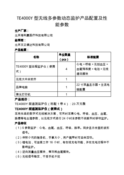
TE4000Y型无线多参数动态监护产品配置及性能参数生产厂家:北京海利赢医疗科技有限公司经销商:北京天正健达科技有限公司产品报价:TE4000Y型遥测监护仪(标配1带4):23万元整TE4000Y型遥测监护仪(便携式)采用先进的数字式无线解决方案,可实时采集心电、呼吸、血压、血氧、脉搏等电生理参数,以无线方式进行24小时全参数不间断实时移动监护。
产品特征(1)5参数监护:心电、血氧、血压、呼吸、脉率。
同步显示全面的波形信号。
(2)体积小巧的随身机,手掌大小,用户佩带时可自由活动。
(3)锂电池,可连续工作16小时,有在线充电功能,并在充电过程中不影响监护。
(4)逆向测量血压模块,微功耗血氧模块。
(5)无线信号稳定,不受手机干扰技术参数遥测人数可同时接受4个病人信号,系统组成1台主机带4个终端,可扩展至100台终端射频特性发射功率≤10mw(50欧,439.92兆赫兹)接受灵敏度≤-105dpm无线调制方式为全数字方式FSK调制便携终端发射盒尺寸:135×88×34mm显示尺寸:52×32mm,分辨率128×64显示内容:心电波、呼吸波、血压值、血压值、脉率值、呼吸率值及呼叫指示、电池指示、导联指示、无线信号指示。
电源使用锂电池可连续工作16小时心电参数采样率=200赫兹,灵敏度=2.5mm/mv,5mm/mv 10mm/mv 输入阻抗≥5M欧导联选择: ⅠⅡⅢⅰⅱⅲ带宽1~25赫兹共模抑制比80Db心率范围30~250bmp,实现方式:体表电位法呼吸测量方式胸阻抗法测量范围5~60bpm报警范围1~100bpm体温测量范围28℃~42℃分辨率正负0.1无创血压测量方式智能型震荡法自动测量工作模式手动/自动使用范围成人、儿童模式测量类型收缩压、舒张压、平均压、脉率测量范围收缩压60~255mmHg舒张压30~200mmHg平均压40~215mmHg血氧饱和度测量范围30~100%分辨率正负1%脉搏脉搏测量范围30~240bpm分辨率1bpm脉搏报警范围0~220bpm可调性能指标:(1)用电模式:使用可充电电池,有在线充电功能,并在充电过程中不影响监护。
人体多生理参数监护仪及远程监测系统研究与设计

中国医疗设备 2020年第35卷 12期 V OL.35 No.1270RESEARCH WORK引言人体生理多参数监护仪可以实时监测病人的血压、血氧饱和度、心率和体温等人体生命体征[1-2],对实时了解病人的状况具有很大的意义,随着Android 手机的普及和物联网技术的发展,使通过手机远程监测病人的生理参数信息成为可能[3-4]。
本文设计了一款多参数监护仪及远程监测系统,该监护仪可以准确测出人体的生理参数信息并将信息通过Wi-Fi 上传到服务器。
远程监测系统通过Android 手机客户端实现多个病人的生理参数信息的查询、显示、保存本地手机SD 卡及语音播报功能,方便及时了解病人的身体状况。
1 人体生理多参数监护仪硬件设计本文设计的监护仪主要测量人体的血压、血氧饱和度、心率和体温四项生理参数信息,监护仪采用STM32F103作为系统的控制芯片,其主要功能是利用人体生理参数各部分的传感器及检测处理电路准确、快速测出人体的生理参数信息,STM32F103内部程序检测到生理参数信息采集完成后,将生理参数信息通过监护仪内部的Wi-Fi 模块实时上传到服务器。
本文设计的多参数监护仪硬件主要包括血压、血氧饱和度、心率和体温的检测及处理电路、Wi-Fi 模块电路,监护仪硬件的结构框图如图1所示。
1.1 人体多生理参数监护仪血压模块硬件设计本文设计的人体血压测量是通过示波法的方法来检测收稿日期:2020-02-24作者邮箱:*************************人体多生理参数监护仪及远程监测系统研究与设计刘彦伟1,孟庆琰1,张兰芹21. 泰安市中心医院 设备科,山东 泰安 271000;2. 山东第一医科大学第二附属医院 医学装备部,山东 泰安 271000[摘 要] 目的 设计一种具有远程监测系统的人体多生理参数监护仪。
方法 采用STM32F103作为主控芯片,根据血压、血氧饱和度、心率和体温的测量原理,设计出各模块的采集和处理电路,手机客户端采用Android 系统平台,设计基于Android 系统的人体生理参数信息查询显示、保存和语音播放功能。
多参数监护系统

Physiology information detecting
目 录
前 言
随着现代医学技术的发展,尤其是电子技术、计算机技术、数字信号处理技术的不断发展,监护仪作为各级各类医院中一种常用设备,得到了广泛应用。现代医学监护仪是一种以测量和控制病人生理参数,并可与已知设定参数进行比较,出现超差而发出报警的一种装置或系统。
关键字:监护仪,单片机,C8051F020,OEM模块,生理信息采集
Abstract
Electrocardiogram (ECG), blood pressure (BP), sphagnum and blood oxygen saturation (SpO2) are the most fundamental bio-indicators of human beings. It's helpful for doctors to measure these biology signals in the first-aid outside the hospital. However, most of the existing monitor systems are inconvenient to be carried and controlled. Therefore, an intillage-timed, portable, low dissipation multi-parametersmonitor system is presented in this paper.
图1-1心电图
随着心脏的搏动,心电图上出现一组特征性的波形(P,QRS,T及U),这些波形对应着心脏的基本电活动。图1-1所示是一个正常状况下的典型的完整心电波形。心电图的各个波、段和间期都有其特殊的生理意义,可作为临床分析心脏疾病的重要参考资料:
基于OMAP3530的多参数监护仪设计

在现代医学中, 采用多参数监护仪, 对危重病 人实施多参数实时监测, 可及时了解病人的心肺功 能及氧合能力等生命体征变化, 有利于提高医生对 患者病情的分析判断 , 及时采取有效的护理或急救 措施, 降低危重病人的死亡率 . 传统基于 PC 平台的多参数监护仪成本高、体 积大、操作复杂 , 使用范围具有局限性. 而采用低 档单片 机为核心 的便携式 多参数监 护仪, 功 能简 单、运算能力差、界面简陋, 只能进行简单的信号 显示, 不能进行数据分析 . 本研究以美国德州仪器公司最新的双核处理器 OMAP3530 为核心, 搭配十二导联心电信号 ( elec trocardiog raph , ECG ) 采 集 模 块、 血 氧 饱 和 度 ( pulse oxygen saturat ion, SPO 2 ) 采集模块、无创血 压 ( non invasiv e b lo od pressure , N IBP ) 采 集模块、 呼吸 ( resp irat ion, R ) 采集 模 块以 及 体温 ( body temperature , TEM P ) 采集模块, 设计了一台具有实 时检测、实时分析和网络传输等功能的新型多参数 监护仪 . 该监护仪既可方便医生实时掌握病人的心 电、血压、血氧等信息, 以 应对患者的病 情突发, 又可帮助健康人群随时关注自己的身体状况 . 是新 一代 ! 数字医疗社区 /医 院 ∀ 在远程医疗方面的重 要发展方向 . 本设计采用的 OMAP3530 处理器由 65 nm 低功 耗工艺 制 造 , 内 部 集 成 了 4 倍 于 当 前 300 MH z ARM 9 器件处理能力的 600 MH z Cortex A8 弹性内核 和 430 MH z的 TM S320C64x+
EASI十二导联系 统能通过式 ( 3) , 转化后得 出十二导联心电信息 . L d = a (A - I ) + b (E - S ) + c(A - S ). ( 3) 其中 , A - I、 E - S、 A - S 为 3 路双极导联数据, 能分 别反映心电向量在冠状面、矢状面和额状面的心电 变化; a、 b、 c 为经大样本研究后得出 的精确相关系 数 . 大量临床研究证实 , 通过 EAS I十二导联系 统获得的心电图非常接近标准的十二导联心电图 .
基于TIOMAP3平台的多参数监护仪设计与实现

基于TIOMAP3平台的多参数监护仪设计与实现多参数监护仪是一种用于监测患者生命体征的医疗设备,能够同时监测和显示多个生理参数,如血压、心率、呼吸频率、体温等。
基于TIOMAP3平台的多参数监护仪设计与实现,将通过以下几个方面进行讨论:硬件设计、软件设计、系统实现和功能实现。
首先,硬件设计是多参数监护仪的基础。
TIOMAP3平台是设计和开发嵌入式系统的一种集成开发平台,其中包含了处理器、存储器、外设接口等基本组件。
在硬件设计中,需要根据监测参数的要求选择合适的传感器,将其接入到相应的外设接口上。
此外,还需要设计电源管理电路、信号放大电路和ADC等模块,以确保传感器采集到的模拟信号能够被处理器正确读取。
其次,软件设计是多参数监护仪实现功能的关键。
TIOMAP3平台上使用的操作系统一般为Linux或Android,可以根据实际需求选择合适的操作系统进行开发。
在软件设计中,需要进行任务调度和实时数据处理。
任务调度可以通过使用RTOS(实时操作系统)或编写相应的任务调度算法来实现。
实时数据处理包括数据采集、数据处理和数据显示等功能,可以使用C/C++等编程语言进行开发。
然后,系统实现是将硬件设计和软件设计相结合的过程。
在系统实现中,需要进行硬件与软件的连接和配置。
首先,将硬件设计完成的电路和模块连接起来,确保传感器能够正常工作,并与处理器进行通信。
然后,根据软件设计的要求编写相应的驱动程序和应用程序,将其加载到处理器中运行。
最后,进行系统测试和调试,确保多参数监护仪的各项功能能够正常使用。
最后,功能实现是多参数监护仪设计与实现的目标。
功能实现包括监测功能和显示功能。
监测功能是多参数监护仪的核心功能,需要能够准确、稳定地采集和监测各项生理参数,并能够及时报警。
显示功能是将监测到的数据以直观的方式展示给医护人员,一般采用液晶显示屏进行显示。
此外,还可以通过网络连接实现远程监测和数据传输功能,以方便医护人员进行远程观察和管理。
基于OMAP3530的远程心电监护系统设计

邮局订阅号:82-946120元/年技术创新测控自动化《PLC 技术应用200例》您的论文得到两院院士关注基于OMAP3530的远程心电监护系统设计Design of a remote ECG monitor system with OMAP3530(兰州大学)马建林张少华郭淼马义德MA Jian-lin ZHANG Shao-hua GUO Miao MA Yi-de摘要:本设计以远程、无线心电监护为背景,依托TI 的双核处理器OMAP3530设计了一种远程便携式无线心电监护系统。
该系统能完成日常心电监护、心电信号分析与报警、心电数据的存储与查询等功能。
系统利用电信CDMA 网络,在任何有该类网络覆盖的区域均可以正常工作。
关键词:心电检测;OMAP3530双核处理器;远程监护;便携式监护系统中图分类号:TP368文献标识码:B Abstract:In this paper,an ECG monitoring system was designed based on TI's OMAP3530dual-core processor.The key points ofthe system were remote,wireless and portable.Routine ECG,ECG analysis,ECG alarm,ECG data storage and ECG data query can be realized by this proposed system.It operates in any situation where CDMA network exists.Key words:electrocardiogram(ECG)detection;OMAP3530dual-core processor ;remote monitoring ;portable monitoring system文章编号:1008-0570(2012)10-0091-02引言近年来,随着人们生活水平的提高、生活节奏的加快、饮食结构的改变以及人口老龄化问题的加重,心血管疾病的发病率迅速上升,已成为威胁人类身体健康的主要因素之一。
可穿戴无线多参数患者监护仪参考设计-德州仪器
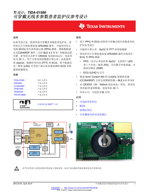
RFRESETTI 设计:TIDA-01580可穿戴无线多参数患者监护仪参考设计说明此参考设计是一款简单的可穿戴多参数患者监护仪,采用单芯片生物传感前端AFE4900器件,可提供同步心电图(ECG)和光体积描记器(PPG)测量。
测量数据通过CC2640R2F 器件(支持BLE 4.2和5)传输到远程位置。
参考设计由单节CR3032电池驱动运行,电池寿命为30天。
用户可使用原始数据计算心率、血氧饱和度(SpO2)、脉搏传导时间(PTT)和ECG 。
两个板载发光二极管(LED)可为用户指示低电量检测和ECG 导联脱落检测情况。
资源TIDA-01580设计文件夹AFE4900产品文件夹CC2640R2F 产品文件夹TPS61099产品文件夹TPS63036产品文件夹TPD1E10B06产品文件夹咨询我们的E2E™专家特性•用于PPG 和ECG 的简单可穿戴无线多参数患者监护仪参考设计•可提供计算心率、SpO2和PTT 的原始数据•使用单芯片生物传感前端AFE4900器件实现同步ECG 和PPG 测量–PPG (光学心率监控和SpO2)支持四个LED和三个光电二极管(PD),具有数字环境消减,可提高信噪比(SNR)–ECG (LEAD I)信号•集成Arm ®Cortex ®-M3和2.4GHz 射频收发器(CC2640R2F)支持无线数据传输–BLE 4.2和5.0•由CR3032(3V 、500mA 纽扣电池)供电,使用高效直流/直流转换器,电池寿命30天•外形小巧,可轻松穿戴应用应用•无线患者监控仪•ECG •脉搏血氧仪•可穿戴健身和活动监测仪该TI 参考设计末尾的重要声明表述了授权使用、知识产权问题和其他重要的免责声明和信息。
System Description Important Disclaimer Information1System Description1.1Introduction to Parameters Measured Using TIDA-01580The TIDA-01580device can be used to measure the following parameters:ECG,PPG,HRM,SpO2,and PTT.ECG is an electrical measurement of the activity in the heart whereas PPG is an optical measurement of the volume of an organ.In principle,ECG uses multiple electrodes to measure the electrical activity of the heart,whereas PPG illuminates the skin and subcutaneous tissue with light of a specific wavelength froma light-emitting diode(LED)to measure organ volume.This light is absorbed,passed through,or reflectedback.A photodiode sensor measures the light that is either transmitted or reflected,depending on where it is placed relative to the LED.The light is then converted to an electrical signal.In both cases,theinformation can be used to determine the heart rate of a person,but each application offers its own set of diagnostic information.ECG focuses on the electrical activity of the cardiac muscle tissue,because the exact sequence of contraction is well-known to trained cardiologists.Physicians use ECG to diagnose all kinds of heart diseases and abnormalities.PPG provides more information about blood flow and blood pressure.This measurement can be conducted at various locations on the body,to examine the blood flow to different regions.When measured closest to the aorta of the heart(for example,the left arm),some additional information can be gained regarding the cardiac output and heart valve function.Oneadvantage that PPG has is the number of skin contacts which are required to measure it.Because users can determine PPG from reflected or transmitted light,only a single point of contact is necessary tomeasure it.This feature allows for easy,continuous,time measurements,which is the most attractiveadvantage to wearable electronics such as fitness trackers.In contrast,ECG requires that the potential be measured across the heart.This means that users need at least two points of contact:positive andnegative.Typically,this connection is only made for a finite period of time.%Sp0211025R u ACrms of Red DC of Red R ACrms of IR DC of IR System Description图1shows the typical waveforms for ECG (blue)and PPG (red).The time difference between the R-peak in the ECG waveform and the arrival of the blood pressure wave in the extremities is another measurement known as PTT.PTT involves simultaneous measurement of ECG and PPG.图1.Introduction to ECG,PPG,and PTTBecause the frequency of both ECG and PPG signals is same,heart rate can be calculated using both waveforms.Mostly green LEDs are used for measuring heart rates.A green LED has often been used in the reflective sensor to extract the PPG signal.Due to its wavelength,green light is known to penetrate the tissue less than higher wavelength LEDs.Hence,more unabsorbed (reflected)light comes out of the tissue with green than with other colors.Sensing the green light from more than one PD or eliminating from more than one LED surrounding the PD helps.Red and infrared (IR)lights are used for pulse oximetry,to estimate the true hemoglobin oxygensaturation of arterial blood.Oxyhemoglobin (HbO2)absorbs visible and infrared IR light differently than deoxyhemoglobin (Hb),and appears bright red as opposed to the darker brown of Hb.Absorption in the arterial blood is represented by an AC signal that is superimposed on a DC signal,representingabsorptions in other substances like pigmentation in tissue,venous,capillary,bone,and so forth.The cardiac-synchronized AC signal is approximately 1%of the DC level.This value is referred to as the perfusion index %.公式1approximates the ratio of ratios,R,and %SpO2is calculated as follows:(1)公式2gives the standard model of computing SpO2.This model is often used in this literature in thecontext of medical devices.However,accurate %SpO2is computed based on the empirical calibration of the ratio of ratios for the specific device.(2)System Description 1.2High-Level System DescriptionTypically wireless,wearable,patient monitors are tied to the human body in such a way that they canmeasure multiple parameters for the body.图2shows a high-level block diagram of such a system.Atypical patient monitor has a radio module,or radio IC,on it and operates over a battery.Thecommunication can be established from a remote location(like a cell phone,tablet,or a computer).图2.System-Level Block Diagram System Description1.3Typical Applications•Wireless Patient Monitor:Wireless patient monitors measure vital signs and send data across to a remote location through wireless technology(Bluetooth®,BLE,Wi-Fi®,or NFC).These monitors aretypically battery-powered and have low operating currents,to work for longer battery life.The solutions are notably compact,unlike Bedside Monitors.•Wearable Fitness and Activity Monitor:Fitness monitors measure both the amount and rate of exercise of a person(for example,miles and pace run),as well as effort expended(for example,throughmonitoring heart rate).Typically,a wristwatch or wrist-worn display is used for control and providingfeedback.Stored data can be downloaded to a computer through a USB or wireless USB dongle.Allparts of the system require ultra-low-power,embedded controllers and low-power RF forcommunication.Heart-rate monitoring and exercise-output monitoring(for example,a running pacesensor or power sensor)require additional signal conditioning.•ECG:Basic functions of an ECG machine include ECG waveform display,either through an LCD screen or printed paper media,and heart rhythm indication,as well as a simple user interface throughbuttons.Additional features are required in more and more ECG products,such as patient-recordstorage using convenient media,wireless or wired transfer,and2D/3D display on a large LCD screenwith touchscreen capabilities.Multiple levels of diagnostic capabilities also assist doctors and peoplewithout specific ECG training to understand ECG patterns and their indication of a certain heartcondition.After the ECG signal is captured and digitized,it is sent for display and analysis,whichinvolves further signal processing.•Pulse Oximeter:The pulse oximeter measures blood oxygenation by sensing the IR and red-light absorption properties of deoxygenated and oxygenated hemoglobin.The oximeter is comprised of asensing probe that attaches to the ear lobe,toe,or finger of a patient,and is connected to a dataacquisition system for calculation and display of the oxygen saturation level,heart rate,and blood flow.Light sources,typically LEDs,shine visible red and IR light.Deoxygenated hemoglobin allows moreinfrared light to pass through and absorbs more red light.Highly oxygenated hemoglobin allows morered light to pass through and absorbs more IR light.The oximeter senses and calculates the amount of light at those wavelengths,proportional to the oxygen saturation(or desaturation)of the hemoglobin.The use of light in the absorbency measurement requires the designer to have a true light-to-voltageconversion using current as the input signal.System Description 1.4System Specifications and Design FeaturesThe TIDA-01580reference design realizes a wearable patient monitor and has following design features:•Simple,wearable,multi-parameter,patient monitor that provides raw data to calculate heart rate, SpO2,and PTT•Single-chip,biosensing,front-end for synchronized ECG and PPG measurements(AFE4900device)–Only device on the market with this level of integration,low power,size,and flexibility–PPG(optical heart-rate monitoring and SpO2)supports4LEDs and3PDs with digital ambient subtraction to improve the SNR–ECG(LEAD I)signals–Flexibility of ultra-low-power modes and integrated FIFO can keep the MCU in sleep mode to increase the battery operation time•Wireless data transfer supporting BLE4.2and5.0–Integrated Arm Cortex-M3and2.4-GHz RF transceiver(CC2640R2F device)–Internal DC/DC converter helps improve the overall efficiency–Built-in,low-battery detection algorithm helps reduce the external components–Better routing in small form factor(all digital peripheral pins can be routed to any GPIO)•Operated from CR3032(3-V,500-mA coin-cell battery),which offers100hours of continuous operation •Low-power(battery life of30days for1second/minute transmission)•Can also be operated using CR2032(3-V,225-mA coin cell battery)with reduced operating time•Plug-in board approach enables easy adaptation to custom PPG sensors1.5Key System Specifications表1lists the different characteristics and specifications of the TIDA-01580board.表1.Key System SpecificationsCHARACTERISTICS SPECIFICATIONSInput voltage(V IN) 1.8V to3V(coin-cell CR3032battery)TX_SUP 4.2VRX_SUP 2.1VIO_SUP 2.1VNumber of LEDs for PPG measurement Three(green,red,and IR)Number of photo diodes for PPG measurement Two(for SFH7072) One(for OCS112)Number of electrodes for ECG measurement Two(Lead-I)for standard operation(support for three electrodes is possible witha few modifications on the board)ECG lead-off detection AC External memory Supported,but not populated onboardLED indications Lead-off detect Low-battery flag BLE statusCommunication SPIInterface to controller8-pin connector(100mil,part number PRPC008SADN-RC) System Overview 2System Overview2.1Block Diagram图3shows the high-level block diagram for the TIDA-01580device,which is a simple,wearable,multi-parameter,patient monitor.The AFE4900is a single-chip,biosensing,front end for synchronized ECG and PPG measurements.The AFE4900device can drive LEDs and support receive signal chains for the photo diodes.The AFE4900device communicates with the CC2640R2F device over SPI(or I2C).TheCC2640R2F is a microcontroller with an integrated Arm Cortex-M3and2.4-GHz RF transceiver.Thedesign supports wired data capture using a JTAG connection,as well as wireless data capture by sending it over BLE through the antenna.The board is powered using a3-V,500-mA coin-cell battery,CR3032.A boost converter(TPS61099)powers TX_SUP for the AFE4900device,which supports the internal LED drivers for PPG measurement.A buck-boost converter(TPS63036)powers RX_SUP and IO_SUP for the AFE4900device and VDDS2and VDDS3for the CC2640R2F device.VDDS for the CC2640R2F device is directly powered by thebattery.The board supports connections to external data-log memory,but it is currently not populated.The board indicates battery power source availability,low-battery detection,BLE connection status,and lead-offdetection through onboard LEDs.All the connections from the main to the external world are protected by ESD diodes(TPD1E10B06).The design contains a main board,an ECG board,and a sensor board.RESET图3.TIDA-01580Block DiagramSystem Overview 2.2Highlighted ProductsKey features of the highlighted devices are mentioned in the following sections.2.2.1AFE4900The AFE4900device is an analog front-end(AFE)for synchronized ECG and PPG signal acquisition.The device can also be used for optical biosensing applications,such as heart-rate monitoring(HRM)andSpO2.The PPG signal chain supports up to four switching LEDs and up to three PDs.The LEDs can be switched on using a fully-integrated LED driver.The current from the PD is converted into voltage by the trans-impedance amplifier(TIA)and digitized using an analog-to-digital converter(ADC).The ECG signal-chain has an instrumentation amplifier(INA),with a programmable gain that interfaces to the same ADC.A right-leg drive(RLD)amplifier set can be used to bias the ECG input pins.AC and DC lead-off detectschemes are supported.The ADC codes from the PPG and ECG phases can be stored in a128-sample first in,first out(FIFO)block and read out using either an I2C or SPI.2.2.2CC2640R2FThe CC2640R2F device is a wireless MCU targeting BLE4.2and5applications.The device is a member of the SimpleLink™ultra-low-power CC26xx family of cost-effective,2.4-GHz RF devices.Low active RF and MCU current and low-power mode current consumption provide excellent battery lifetime and allow for operation on small coin-cell batteries and in energy-harvesting applications.The SimpleLink BLECC2640R2F device contains a32-bit Arm Cortex-M3core,which runs at48MHz as the main processor and a rich peripheral feature set,which includes a unique ultra-low power sensor controller.This sensor controller is ideal for interfacing external sensors and for collecting analog and digital data autonomously while the rest of the system is in sleep mode.Thus,the CC2640R2F device is great for a wide range of applications where long battery lifetime,small form factor,and ease of use are important.The power and clock management and radio systems of the CC2640R2F wireless MCU require specific configuration and handling by software,which has been implemented in the TI-RTOS,to operate correctly.2.2.3TPS61099The TPS61099boost converter uses a hysteretic control topology to obtain maximum efficiency at minimal quiescent current.The TPS61099device only consumes1-μA quiescent current under a light loadcondition and can achieve up to75%efficiency at a10-μA load with a fixed output voltage version.The TPS61099device can also support up to300-mA output current from3.3V to5V conversion and achieve up to93%at a200-mA load.The TPS61099device also offers both Down Mode and Pass-Throughoperations for different applications.In Down Mode,the output voltage can still be regulated at a target value even when the input voltage is higher than the output voltage.In Pass-Through Mode,the output voltage follows the input voltage.The TPS61099x device exits Down Mode and enters into Pass-Through Mode when VIN>VOUT+0.3V.The TPS61099x device supports true shutdown function when it isdisabled,which disconnects the load from the input supply to reduce the current consumption.TheTPS61099x device offers both an adjustable output voltage version and fixed output voltage version.The TPS61099x device is available in a6-ball,1.23-mm×0.88-mm,WCSP package. System Overview 2.2.4TPS63036The TPS63036is a noninverting,buck-boost converter capable of providing a regulated output voltage from an input supply that can be higher or lower than the output voltage.The buck-boost converter isbased on a fixed-frequency,pulse width modulation(PWM)controller,which uses synchronousrectification to obtain maximum efficiency.At low-load currents,the converter enters a power-save mode to maintain high efficiency over a wide-load current range.The power save mode can be disabled,forcing the converter to operate at a fixed switching frequency.The maximum average current in the switches is limited to a typical value of1000mA.The output voltage is programmable using an external resistordivider.The converter can be disabled to minimize battery drain.2.2.5TPD1E10B06The TPD1E10B06device is a single-channel,electrostatic discharge(ESD),transient voltage suppression (TVS)diode in a small0402package.This TVS protection product offers±30-kV contact ESD,±30-kV IEC air-gap protection,and an ESD clamp circuit,with a back-to-back TVS diode for bipolar orbidirectional signal support.The0402package is an industry standard and is convenient for component placement in space-saving applications.2.3System Design Theory and Design ConsiderationsThis section explains the design theory(and equations,if required)for each of the devices used in thedesign.2.3.1AFE4900and Power Supply图4shows different connections for the AFE4900device.The AFE4900device needs three power supplies:TX_SUP,RX_SUP,and IO_SUP.TX_SUP(4.2V)is generated using the TPS61099device.RX_SUP(2.1V)is generated using the TPS63036device.IO_SUP is the same as RX_SUP.For PPG measurement,the LEDs are driven using the TX2,TX3,and TX4pins(TX1is not connected in the design).The reflected signals are detected using PDs connected to the INP-INM and INP2-INM2pins (INP3-INM3pins are not connected in the design).For ECG measurement,the signals coming from electrodes are connected to the INP_ECG andINM_ECG pins.The right-leg drive signal is available on RLD_OUT pin.The BG pin is connected to the internal bandgap voltage.The BG pin is decoupled using a0.1-µFcapacitor(C11)on the board.System Overview 图4.AFE4900Connections SchematicFor the AFE4900device,RX_SUP is filtered using an LC filter consisting of the ferrite bead L1andcapacitors C6and C7. System Overview11ZHCU476–April 2018可穿戴无线多参数患者监护仪参考设计表2lists the connections between the AFE4900and CC2640R2F devices.表2.Connections Between AFE4900and CC2640R2FAFE4900PIN NUMBERFUNCTION CC2640R2F PINNUMBERFUNCTION COMMENTSE1/RESET 6DIO_1Reset for the AFEA4I2C_SPI_SEL N/A N/A Selection between SPI and I 2C.For this design,SPI is selected,so this pin is connected to RX_SUP through a 0-Ωresistor (R2).F3I2C_CLK 16DIO_10SPI_CLK F2I2C_DAT 14DIO_8SPI_IN E2SDOUT 15DIO_9SPI_OUT E3SEN 5DIO_0AFE_SPI_END3PROG_OUT121DIO_15F4ADC_RDY 28DIO_18ADC ready signal F1CLK 29DIO_19AFE clockB4CONTROL1N/AN/AEnables or disables the internal LDO.For this design,the internal LDO is enabled,so this pin is connected to GND through a 0-Ωresistor (R4).2.3.2CC2640R2F Microcontroller图5shows the schematic for configuring the CC2640R2F MCU.图2640R2F MCU SchematicThe VDSS power supply for the MCU,2.1V,is derived using the TPS63036device.The VDDR power supply is generated using the internal DC/DC of the CC2640R2F MCU,and L8,C20,C25,and C27form the filter components for the same.Y1is the 24-MHz,high-frequency,external clock and Y2is the 32-kHz,low-frequency,external clock.The GPIO pins of the CC2640R2F MCU (DIO_0to DIO_30)interface with different functions such as Memory interface lines,AFE4900interface lines,SPI communication,LED drives,and so on.System Overview 12ZHCU476–April 2018可穿戴无线多参数患者监护仪参考设计The RF front end is used in differential-ended configurations with internal biasing.A BalunLFB182G45BG5D920device is used for the RF front end and tuned for application.J7is a connector for conducted RF measurements (if required).The antenna is a PCB antenna.图6.Decoupling for CC2640R2F MCUVBATT is connected to VDSS through L5(a GHz noise-suppression chip ferrite bead),providing a low-noise supply to the MCU.C19and C22are the decoupling capacitors.A 2.1V is connected to the VDDS2and VDDS3pins through L6(a GHz noise-suppression chip ferrite bead),providing a low-noise supply to the MCU.C23and C24are the decoupling capacitors (see 图6).VDDS2-3TDIJTAG_TCKC JTAG_TMSC CC_RESETVDDSSystem Overview13ZHCU476–April 2018可穿戴无线多参数患者监护仪参考设计图7.MCU Programming ConnectorThe MCU is programmed using a JTAG connection,as shown in 图7.The connector inputs are protected by ESD diodes (TPD1E10B06DPYR)from Texas Instruments.The TPD1E10B06device is a single-channel,ESD,TVS diode in a small 0402package.This TVS protection product offers ±30-kV contact ESD,±30-kV IEC air-gap protection,and an ESD clamp circuit,with a back-to-back TVS diode for bipolar or bidirectional signal support.2.3.3PPG MeasurementFor PPG measurement,three LEDs and two PDs are used in a single package.表3lists details about the OCS112(from Taiwan Biophotonic Co.)and SFH7072(from OSRAM ®).表3.Optical SensorsSENSOR OCS112SFH7072Number of LEDs 34Number of PDs 12LED1color Red Green LED1wavelength 655nm 526nm LED2color IR Green LED2wavelength 945nm 526nm LED3color Green Red LED3wavelength 525nm 660nm LED4color –IR LED3wavelength –950nm LED1VF (typ) 2.1 1.3LED1VF (max) 2.4 1.8LED2VF (typ) 1.4 2.1LED2VF (max) 1.55 2.8LED3VF (typ) 3.23LED3VF (max) 3.7 3.4LED4VF (typ)–3LED4VF (max)–3.4System Overview 14ZHCU476–April 2018可穿戴无线多参数患者监护仪参考设计The Sensor boards are designed to fit on the main board with 5-pin connectors,based on the LEDs and PDs available in the Optical Sensor.All the LEDs are configured in push-pull (common anode mode).See 图8and 图9for the connection diagrams.图8.Sensor Board Schematic With SFH7072Device图9.Sensor Board Schematic With OCS112DeviceThe Sensor boards are fit onto the main board using the J1and J2connector,as shown in 图10.1234L3DLW31SN900SQ2LIN2_PIN2_NPD2_APD2_C1234L2DLW31SN900SQ2LIN_PIN_NPD1_APD1_CSystem Overview15ZHCU476–April 2018可穿戴无线多参数患者监护仪参考设计图10.PPG Connection From Sensor Board to AFE4900Device on Main BoardThe J1connector has 5connections:TX_SUP,TX drive pins,and GND.The J2connector has 5connections:PD1Anode and Cathode,PD2Anode and Cathode,and GND.The connector inputs are protected using ESD diodes (TPD1E10B06DPYR)from Texas Instruments.The TPD1E10B06device is a single-channel,ESD,TVS diode in a small 0402package.This TVS protection product offers ±30-kV contact ESD,±30-kV IEC air-gap protection,and an ESD clamp circuit with a back-to-back TVS diode for bipolar or bidirectional signal support.The TX_SUP pin is decoupled using a 33-µF capacitor.The PD signals are filtered using SMD Common Mode Chokes (having specifications as 90Ωat 100MHz,370-mA DCR 300m Ω).The chokes help in improving the immunity to external common mode noise signals and improve overall SNR of the system.2.3.4ECG MeasurementThe single-lead ECG measurement can be done using either two electrodes or three electrodes.2.3.4.1Two-Electrode Configuration (Dry Electrodes)This configuration does not need a third wire or connection for RLD.The common mode voltage is provided to the inputs using a resistor divider network,as shown in 图11.The signals coming from the electrodes are AC-coupled using capacitors.System Overview 16ZHCU476–April 2018可穿戴无线多参数患者监护仪参考设计图11.Interface for ECG Measurement (Two Electrodes)2.3.4.2Three-Electrode Configuration (Wet Electrodes)This configuration needs a third wire or connection for RLD.The common mode voltage is provided to the inputs using the RLD terminal shown in 图12.The signals coming from the electrodes are directly connected to the inputs of the AFE.图12.Interface for ECG Measurement (Three Electrodes)OUT REF R35R36V V R36 uSystem Overview 18ZHCU476–April 2018可穿戴无线多参数患者监护仪参考设计2.3.5Selecting TX Supply (TX_SUP)Value for Driving LEDs表5shows the recommended TX_SUP voltage range,taken from the AFE4900device data sheet.(1)V LED refers to the maximum voltage drop across the external LED (at maximum LED current).This value is usually governed by the forward drop voltage (V FB )of the LED.V HR refers to the headroom voltage of the LED driver as listed in 表6for various LED current settings.The extra 0.3V is the suggested margin.表5.Recommended TX_SUP ValueMINMAX UNIT RX_SU P Receiver supply LDO bypassed 1.8 1.9V LDO enabled2.0Minimum (3.6,TX_SUP)IO_SUPI/O supply1.7RX_SUPV TX_SUP Transmitter supplyWhen operating at the maximum current setting 3.0or (0.3+V HR +V LED )(1),whichever is greater5.25V Digital inputs 0IO_SUP V Analog inputs0RX_SUPV T AOperating temperature range–2070°C表6shows the headroom voltage,V HR .(1)Full-scale current per LED.(2)Typical voltage headroom required for the LED driver.表6.Headroom VoltagesILED_FS REGISTER CONTROLONE LED DRIVER ON TWO LED DRIVERS ON,THROUGH ONE LED TWO LED DRIVERS ON,THROUGH TWO LEDs FULL-SCALE CURRENT (1)V HR (2)FULL-SCALE CURRENT (1)V HR (2)FULL-SCALE CURRENT (1)V HR (2)050mA 320mV 100mA 370mV 50mA 345mV 1100mA600mV200mA650mV100mA625mVTX_SUP =V LED +V HR +0.3=3.2+0.625+0.3=4.125V Select TX_SUP =4.2V.2.3.6Generating TX Supply for Driving LEDs表7.Specifications for TX_SUPPARAMETER VALUE Input voltage 1.8V to 3.0VOutput voltage 4.2V Output current 50mA Output voltage ripple±50mV2.3.6.1Programming Output VoltageThe output voltage is programmed to 4.2V using 公式3,where V REF =1.0V.For best accuracy,the current following through R36should be 100times larger than the FB pin leakage current.(3)Because V OUT =4.2V and R36=100k Ω,R35=320k Ω.TI recommends high-accuracy resistors for better output voltage accuracy.The TIDA-01580device uses both resistors with 0.5%tolerance.Internal Vref = 1.0VINOUT IN LH OUT V V V 1.8 4.2 1.80.85f 1.48MHz L I V 2.20.35 4.2u u K u u u u P u u LH IN LIM OUT max OUTI V I 2I V §·u u K¨¸©¹ System Overview19ZHCU476–April 2018可穿戴无线多参数患者监护仪参考设计2.3.6.2Maximum Output CurrentThe maximum output capability of the TPS61099device is determined by the input-to-output ratio and the current limit of the boost converter.公式4shows I OUT(max)=300mA (V IN =1.8V,I LIM =1A,I LH =350mA,η=85%,and V OUT =4.2V).(4)2.3.6.3Input and Output Capacitor SelectionFor the best output and input voltage filtering,TI recommends low-ESR X5R or X7R ceramic capacitors.The input capacitor minimizes input voltage ripple,suppresses input voltage spikes,and provides a stable system rail for the device.An input capacitor value of 10μF (C47)is used to improve transient behavior of the regulator and EMI behavior of the total power supply circuit.TI recommends placing a ceramic capacitor as close as possible to the VIN and GND pins of the IC.For the output capacitor of the VOUT pin,ceramic capacitors (C49and C53)are placed as close aspossible to the VOUT and GND pins of the IC.This capacitor must be placed as close as possible to the VOUT and GND pins of the IC.From the power-stage point of view,the output capacitor sets the corner frequency of the converter,while the inductor creates a Right-Half-Plane-Zero.Consequently,with a larger inductor,a larger output capacitor must be used.The TPS61099x device is optimized to work with the inductor from 1μH to 2.2μH,so the minimal output capacitor value is 20μF (nominal value).Increasing the output capacitor makes the output ripple smaller in PWM mode.2.3.6.4Switching FrequencyThe switching frequency is calculated as 公式5.(5)图13shows the schematic for the boost converter,TPS61099.图13.TPS61099Boost Converter (V OUT =4.2V)Rload R = 105 ŸSystem Overview 20ZHCU476–April 2018可穿戴无线多参数患者监护仪参考设计2.3.6.5WEBENCH ®Simulation for TPS61099Boost Converter图14and 图15show the WEBENCH ®simulation for the TPS61099boost converter.For any custom requirement,simulation is available on the TPS61099product page .图14.WEBENCH ®Simulation for TPS61099Boost Converter (Schematic)图15.WEBENCH ®Simulation for TPS61099Boost Converter (Test Results)。
病人远程心电监护系统设计与实现

病人远程心电监护系统设计与实现心电监护在医疗领域起着重要的作用,能够实时检测病人的心电信号,帮助医务人员及时发现和处理心律失常等疾病。
然而,传统的心电监护方式受限于时间和空间,且需要专业人员在现场进行监护。
为了解决这一问题,病人远程心电监护系统被引入,该系统设计旨在通过互联网实现医生对病人心电信号的远程监护,为医务人员提供更便利的工具和病人更舒适的体验。
本文将针对病人远程心电监护系统的设计与实现进行详细探讨,包括系统架构、关键功能以及实施所需技术等方面。
一、系统架构病人远程心电监护系统的架构主要由三个关键部分构成:心电监测设备、数据传输网路和数据接收端,如下图所示:1. 心电监测设备:病人佩戴的心电传感器将心电信号转换为数字信号,并通过蓝牙或其他无线通信技术传输到数据传输网路。
2. 数据传输网路:采用互联网作为数据传输的通道,确保医生可以随时随地实时接收心电信号。
该网路应具备稳定、快速、安全的特性,以保护病人的隐私。
3. 数据接收端:医生通过电脑、平板或智能手机等设备接收并显示心电信号。
该设备上运行着专门的心电监护软件,能够实时解析、展示心电波形图和相关数据,并提供有关病人的详细信息。
二、关键功能病人远程心电监护系统具有以下几项关键功能,以满足临床医生和病人的需求:1. 实时监测:系统能够实时地采集和传输心电信号,医生能够随时随地对病人心电状态进行监测和评估,并及时采取必要的措施。
2. 报警机制:系统具备心电异常报警功能,能够检测出心律失常、心脏骤停等紧急状况,并及时向医生发送报警信息,以便医生能够快速作出反应。
3. 数据记录与分析:系统将心电信号记录在数据库中,医生可以回溯病人的历史心电数据,进行长期分析和比较。
同时,系统还提供数据分析算法,用于辅助医生进行心电信号的解读和诊断。
4. 远程诊断:医生通过数据接收端对病人的心电信号进行解读和诊断,并可以远程为病人开具处方、调整治疗方案等。
这样可以减少医生和病人之间的距离,提高诊疗效果。
远程心电实时监护系统设计

远程心电实时监护系统设计远程心电实时监护系统设计来源:互联网目前世界上有很多心脏疾病患者由于得不到及时的救助,生命常常受到威胁。
传统的心电监护仪(什么是心电监护仪)限制了患者的自由,而且不具备实时监护功能,对于那些威胁到患者生命的突发疾病帮助不大。
随着无线通信技术的不断发展,现在已经有了便携式监护仪(监护仪原理),这类仪器让实时监护成为可能。
本文主要介绍了心电监护仪应用案例之远程心电实时监护系统设计。
利用GPRS无线数据通信技术,可以将实时监护与Holter相结合,患者佩戴这种便携式监护仪(心电监护仪的维护)可以自由活动,而且还能随时随地得到心电监护。
当有紧急情况发生时,医生可以根据全面的心电数据分析患者心脏状况,使患者得到即时的救助。
一、远程心电实时监护系统概述远程心电实时监护系统包括四个部分:监护仪(病人终端)、PDA(医生终端)、监护服务器以及心电数据服务器。
系统结构。
监护仪由患者随身佩带,以400Hz或500Hz的采样频率对患者心电信号采样,并把心电数据通过GSM/GPRS网络发送给监护服务器,数据的实时性由监护服务器和监护仪之间的控制信息控制。
PDA接收来自监护服务器的数据,并根据心电分析的结果通过数据服务(GPRS数据服务)和短消息(SMS)通知监护仪。
监护服务器负责接收转存病人端全部心电数据,实时分析及回放分析;同时向PDA转发实时心电数据,利用控制信息来协调实时心电数据的收发。
心电数据服务器存储所有心电数据、患者信息以及设备信息,除了在监护过程中存储心电数据外,心电数据服务器还负责注册患者和设备信息及管理数据库远程访问等任务。
二、监护仪硬件平台简介监护仪硬件主要由单片机、电源模块、心电信号采集放大模块、扩展NAND Flash、LCD驱动模块及GSM/GPRS无线通信模块组成。
三、软件系统关键技术监护仪软件系统的核心是管理Flash、GPRS网络、无线模块的GSM功能及LCD。
3.1Flash管理Flash存储器用于存储心电数据和控制信息,以保证心电数据在断电时不遗失及日后查看监护过程的相关控制信息。
多参数监护仪产品技术要求
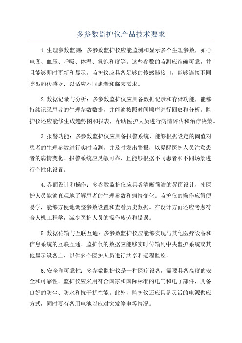
多参数监护仪产品技术要求1.生理参数监测:多参数监护仪应能监测和显示多个生理参数,如心电图、血压、呼吸、体温、氧饱和度等。
这些参数的监测应准确可靠,并且能够即时更新和显示。
监护仪应具备足够的传感器接口,能够连接不同类型的传感器,以适应不同患者和临床需求。
2.数据记录与分析:多参数监护仪应具备数据记录和存储功能,能够持续记录患者的生理参数数据,并能够按照时间顺序进行回放和分析。
监护仪还应能够生成趋势图和报表,帮助医护人员进行病情评估和治疗决策。
3.报警功能:多参数监护仪应具备报警系统,能够根据设定的阈值对患者的生理参数进行实时监测,并及时发出警报,以提醒医护人员注意患者的病情变化。
报警系统应灵敏可靠,且能够根据不同患者和不同场景进行个性化设置。
4.界面设计和操作:多参数监护仪应具备清晰简洁的界面设计,使医护人员能够直观地了解患者的生理参数和病情变化。
监护仪的操作应简便易学,能够方便地调整参数设置和查看历史数据。
在设计方面还应考虑符合人机工程学,减少医护人员的操作疲劳和错误。
5.数据传输与互联互通:多参数监护仪应能够实现与其他医疗设备和信息系统的互联互通。
监护仪的数据应能够实时传输到中央监护系统或其他显示设备上,以供多个医护人员进行共享和远程监控。
6.安全和可靠性:多参数监护仪是一种医疗设备,需要具备高度的安全和可靠性。
监护仪应采用符合国家和国际标准的电气和电子部件,具备良好的防尘、防水和抗干扰性能。
此外,监护仪还应具备灵活的电源供应方式,同时要有备用电池以应对突发停电等情况。
7.人性化设计和易维护性:多参数监护仪的外观设计应朴实大方,易于清洁和消毒。
设备的各部分应易于拆卸和更换,以便于日常维护和维修。
监护仪的使用说明和维护手册应详尽清晰,附有故障诊断和排除的方法。
综上所述,多参数监护仪的产品技术要求非常多样化,并且需要满足医疗实际需求和标准要求。
随着科技的发展和医疗需求的不断变化,多参数监护仪的技术要求也将不断更新与完善。
多参数监护仪技术参数
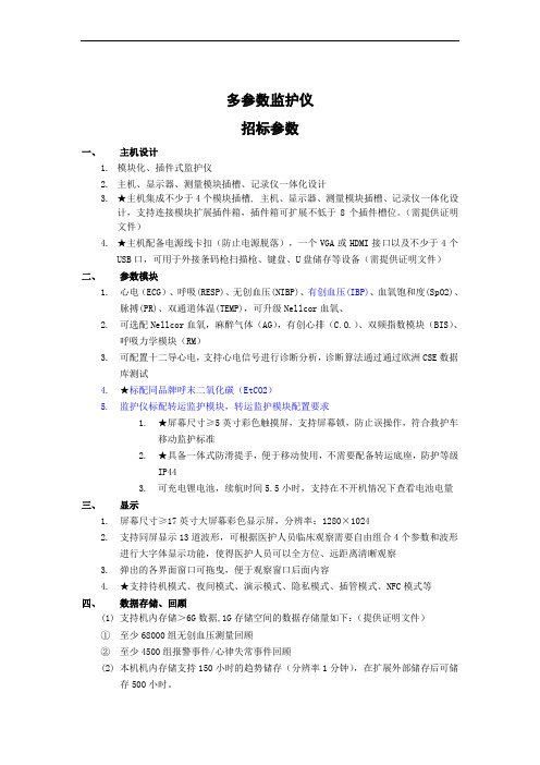
多参数监护仪招标参数一、主机设计1.模块化、插件式监护仪2.主机、显示器、测量模块插槽、记录仪一体化设计3.★主机集成不少于4个模块插槽, 主机、显示器、测量模块插槽、记录仪一体化设计,支持连接模块扩展插件箱,插件箱可扩展不低于8个插件槽位。
(需提供证明文件)4.★主机配备电源线卡扣(防止电源脱落),一个VGA或HDMI接口以及不少于4个USB口,可用于外接条码枪扫描枪、键盘、U盘储存等设备(需提供证明文件)二、参数模块1.心电(ECG)、呼吸(RESP)、无创血压(NIBP)、有创血压(IBP)、血氧饱和度(SpO2)、脉搏(PR)、双通道体温(TEMP),可升级Nellcor血氧、2.可选配Nellcor血氧,麻醉气体(AG),有创心排(C.O.)、双频指数模块(BIS)、呼吸力学模块(RM)3.可配置十二导心电,支持心电信号进行诊断分析,诊断算法通过通过欧洲CSE数据库测试4.★标配同品牌呼末二氧化碳(EtCO2)5.监护仪标配转运监护模块,转运监护模块配置要求1.★屏幕尺寸≥5英寸彩色触摸屏,支持屏幕锁,防止误操作,符合救护车移动监护标准2.★具备一体式防滑提手,便于移动使用,不需要配备转运底座,防护等级IP443.可充电锂电池,续航时间5.5小时,支持在不开机情况下查看电池电量三、显示1.屏幕尺寸≥17英寸大屏幕彩色显示屏,分辨率:1280×10242.支持同屏显示13道波形,可根据医护人员临床观察需要自由组合4个参数和波形进行大字体显示功能,使得医护人员可以全方位、远距离清晰观察3.弹出的各界面窗口可拖曳,便于观察窗口后面内容4.★支持待机模式、夜间模式、演示模式、隐私模式、插管模式、NFC模式等四、数据存储、回顾(1)支持机内存储>6G数据,1G存储空间的数据存储量如下:(提供证明文件)①至少68000组无创血压测量回顾②至少4500组报警事件/心律失常事件回顾(2)本机机内存储支持150小时的趋势储存(分辨率1分钟),在扩展外部储存后可储存500小时。
多功能人体多生理参数远程监护仪

2018年 / 第4期 物联网技术13图3 力学模型与平衡装置及坐标系2.3 自平衡两轮车的工作原理根据车体向左或向右倾斜的角度,控制偏转电机带动前后飞轮绕偏转轴偏转从而产生修正力矩,使车体保持竖直状态。
2.4 系统总体设计自平衡两轮车系统以STM32F103 单片机为控制核心。
通过姿态传感器采集车身的左右倾斜角度,把采集到的数据传输到单片机,单片机通过控制算法,根据输入的角度数据得出偏转电机的偏转数据,从而控制偏转电机偏转,产生修正力,使系统达到自平衡。
此外,通过航模遥控器可以无线遥控两轮车的前进、加速、减速、转向等动作。
3 创新点(1)巧妙利用陀螺效应,使小车实现自平衡,同时,由且市面上大多数自平衡车只能在运动状态下保持平衡,而我们设计的小车由于设计原理的独特性可以在保持原地不动的情况下保持平衡。
(2)我们采用的操纵方式不同于其他利用陀螺效应的自平衡车。
通过提前设定好不同程序,以远程遥控的方式来控制小车,在特殊路段行驶时采用远程控制方式可保障小车安全通过,在执行特殊任务时也可采用远程遥控的方式将所要运送的物品运送到目的地。
由于小车的抗干扰能力极强,在执行任务的过程中,无需担心来自侧面的撞击导致小车失去平衡。
4 市场前景在农业方面,该系统可以被用来帮助农业工作者采集土壤样本,采摘农产品,喷洒农药等。
在交通方面,该平衡车既能够载人又能够载物。
载人时,可作为一般电动车驾驶,也可让行动不便的人更好地行动;载物时,可以由人进行远程控制,将货物送到指定目的地。
在军事方面,可以侦察敌情,传递信息,又可携带炸药,减少我方人员伤亡。
总体来说,本自平衡车体积小,速度快,抗干扰能力强,路段适应性强,应用范围广泛。
1 作品简介多功能人体多生理参数远程监护仪可快速而准确地检测人体血压、血糖、血氧饱和度、体温以及心率、心电等重要的人体生理参数信息并加以存储、显示、打印、上传云端。
有需要时还可通过通信线连接至PC 上位机,进行更深层次的处理,便于使用者及其家人或医生关注这几个重要的生理参数。
家用多参数监护仪系统的设计与实现

家用多参数监护仪系统的设计与实现摘要:对传统的多参数监护仪功能进行改进和创新,设计了家用多参数监护仪系统,实现对佩戴使用者的生命体征进行实时监测、完成数据采集以及实现远程健康监护的功能,摆脱了医院床边使用的环境限制,让用户在家就可以进行生命各项体征的监测,为病人的健康预防、诊断和治疗提供了一个有效的手段,解决了病人要经常去医院进行体检的出行的困难,也免去了繁琐的排队预约问诊的流程,同时大大提高了医护人员的工作效率,缓解了医院问诊难,就医难的问题。
本设计能真实有效的监护到人体各种参数,非常适合在家庭环境中使用。
关键字:多参数监护;ESP8266;可视化1 引言当前,我国慢性病呈现出“患病人数多、患病时间长、医疗成本高、服务需求大”的特点。
如果能够动态监测健康指标,及时获得的反馈与帮助,帮助慢性病患者自我管理,有助于应对慢性病高发的挑战。
将能够提升效率,减少就医次数,节约医疗费用和人力成本。
随着信息技术高速发展,监护仪正在逐渐从传统的医疗监护转变为自主监护,朝着家用、个人保健、便携、低功耗等趋势发展,出现了许多便捷的多参数监护仪。
然而,现在市面上的监护仪,普遍存在价格昂贵、设备体积大、设备维护困难、信息化程度不够、功耗大、需要专业人员操作等问题,难以向基层医疗社区、家庭等不同环境推广,无法做到准确且实时地反映使用者的身体健康状况。
本文设计的家用多参数监护仪包含医用血压计、血氧仪、呼吸检测仪、体温计、心电监测仪设备,可以精准且实时地反映佩戴者的各项生理指标参数,通过网络保存到数据库服务器中,供医生对数据进行分析处理,给出治疗建议。
2 系统总体设计2.1系统结构图图1 系统架构图系统架构如图1所示,由ESP8266作为主控芯片,控制各种传感器采集人体的各项生理参数,对采集到的各项生理参数进行封装,通过WiFi模块上传到路由器;路由器再将封装好的数据上传到云端服务器,云端服务器将数据保存到数据库中,管理系统可以对数据库数据进行可视化展示,供医生对病情进行分析给出诊断意见,同时能把诊断报告发送到用户手机APP上。
生理多参数远程监护系统的研究进展
万方数据
廉,为远程医疗、远程监护等提供了良好的基础支持ti n]。 1.2基于无线通信网的远程监护 基于Interact的远程监护系统由于其设备的局限,只能 应用于固定环境,使得受监护人群的活动范围仍然受到限制。 此外,系统必须是可以接入]nternet的工作站或Pc机,从而 造成较高的功耗和成本f_”。像心电这样重要的生理参数,需 要随时监护,仅仅依靠该系统进行监护仍然不能体现出系统 的优势。因此,基于无线通信网的心电远程监护系统日益成 为研究的重点。 基于无线通信网的远程监护系统主要由监护终端、无线 远程传输网络和医院或社区监护中心组成[121。近年来,随着 生物医学传感器的小型化【l”,用于采集和传输生理数据的监 护终端趋于小型化,产生了便携式生理信号采集器。与无线 远程传输网络结合起来,使患者可以在一定范围内自由移动, 而不必受监护装置的限制03,1410当前较为常见的无线通信技 术有CDMAt”1、GPRsl珐141以及蓝牙技术its,t61等。 1.2.1基于GPRS的无线远程监护。GPRS(General Packet
clinicalb
and has become
focus
of study in the field of biomedicM engineering.This article mainly introduces the
present situation
(a.Biomedical Engineering Center;
monitoring,or monitor is
need
to
get
physiological
in
parameters,present
methods limit spital,which
多参数监护仪
1.1.1 单参数监护仪:如血压监护仪、血氧饱和度监护仪、心电监护仪等。
1.1.2 多功能、多参数综合监护仪:可同时监护心电、呼吸、体温、血压、血氧等参数。
1.1.3 插件式组合监护仪:它是由各个方面分立可拆卸的生理参数模块和一台监护仪主机构成,用户可按照自己的要求选购不同的插件模块组成一个适合自己特殊要求的监护仪。
多参数监护仪能为医学临床诊断提供重要的病人信息,通过各种功能模块,可实时检测人体的心电信号、心率、血氧饱和度、血压、呼吸频率和体温等重要参数,实现对各参数的监督报警。信息存储和传输,是一种监护病人的重要设备。
系统工作原理
便携式微电脑多参数生理监护仪的主机由两个16位微控制器80C196组成。 系统通过信号检测与预处理模块将生物医学信号转换成电信号,并进行干扰抑制、信号滤波和放大等预处理。然后,通过数据提取与处理模块进行采样、量化,并对各参数进行计算分析,结果与设定阈值比较,进行监督报警,将结果数据实时存储到RAM,并可实时传送至PC机上,在PC机上可实时显示各参数值。
振动法是测量血压的方法。它的原理是利用袖带充气到一定压力时完全压迫动脉血管并阻断动脉血流,然后随着袖带压力减小,动脉血管将出现:完全阻闭-渐开-全放开的变化过程。在全过程中,动脉血管壁的搏动将在袖带内的气体中产生气体振荡,这种振荡与动脉收缩压、舒张压和平均压存在确定的对应关系。因此通过测量、记录和分析放气过程中袖带内的压力振动波即可获得被测部位的收缩压、平均压和舒张压。
多参数监护仪的基本原理
时间:2009-07-23 13:48:22 来源: 作者:hxx
多参数监护仪在现代医学中的应用越来越广泛。本文简述了多参数监护仪的分类,并着重阐述了心电、血压、血氧、呼吸、体温、呼吸末二氧化碳监护的原理。
- 1、下载文档前请自行甄别文档内容的完整性,平台不提供额外的编辑、内容补充、找答案等附加服务。
- 2、"仅部分预览"的文档,不可在线预览部分如存在完整性等问题,可反馈申请退款(可完整预览的文档不适用该条件!)。
- 3、如文档侵犯您的权益,请联系客服反馈,我们会尽快为您处理(人工客服工作时间:9:00-18:30)。
远程多参数动态实时监护仪设计
陈海金 , 张 跃
( ) 清华大学 深圳研究生院嵌入式系统与技术实验室 , 广东 深圳 5 1 8 0 5 5
、蓝 牙 等 技 术,提 出 了 带 摘 要 : 为了提高对心血管患者有效动态心电监护 , 通 过 使 用 高 速 处 理 器 、 触 摸 屏 、3 G、 W i i -F A n d r o i d 系统的远程动态监护仪方案 。 介绍了使用 A RM 1 1 处理器的 心 电 监 护 仪 软 硬 件 设 计 , 包 括 该 系 统 硬 件 启 动 、 存 储 、 电源 、 心电采集 、 呼吸采集 、 红外体温采集 、 血氧饱 和 度 采 集 、A n d r o i d系 统 驱 动 移 植、生 理 参 数 驱 动 开 发 和 监 护 仪 应 用 程序开发 。 它解决了以往 A RM 7 监护仪交互能力弱 、 传输效率差 、 检测不稳定等问题 , 为患者提供更人性化操作界面 。 关键词 :A n d r o i d 系统 ; 远程医疗 ; 多参数 ;3 G 通信 ; 动态实时监护 )1 中图法分类号 :T P 3 6 8 . 1 文献标识号 :A 文章编号 : 1 0 0 0 7 0 2 4( 2 0 1 2 2 4 5 0 1 0 8 - - -
2 0 1 2年1 2月 第3 3卷 第1 2期
计算机工程与设计
C OMP UT E R E NG I N E E R I NG AN D D E S I GN
D e c . 2 0 1 2 V o l . 3 3 N o . 1 2
r e a l t i m e m o n i t o r D e s i n o f r e m o t e d n a m i c m u l t i a r a m e t e r -p - g y
CHE N H a i i n, Z HANG Y u e - j
:T ,b ,T A b s t r a c t u a r d i a n s h i a t i e n t s r o c e s s o r o i m r o v e a n e f f i c i e n t d n a m i c o f c a r d i o v a s c u l a r u s i n h i h s e e d o u c h g p p p p y y g g p ,3 , r o o s e d . S c r e e n G, W i F i a n d B l u e t o o t h t e c h n o l o a d e s i n o f r e m o t e d n a m i c E C G m o n i t o r b a s e d o n a n d r o i d s s t e m i s - p p g y g y y , , , , T h e h a r d w a r e a n d s o f t w a r e d e s i n s a r e i n t r o d u c e d w h i c h c o n t a i n s s s t e m s t a r t u a n d s t o r a e o w e r s u l E C G a c u i s i t i o n g y p g p p p y q , 、p o o r r e s i r a t i o n a c u i s i t i o n I R t e m e r a t u r e d e t e c t i o n a n d S O 2d e t e c t i o n . P r o b l e m s o f w e a k i n t e r a c t i o n c o mm u n i c a t i o n e f f i c i e n c a n d p q p y u n s t a b l e E C G s i n a l s d e t e c t i o n o c c u r r e d i n m o b i l e E C G m o n i t o r w i t h A RM 7p r o c e s s o r a r e s o l v e d i n t h e d e s i n .A h u m a n g g r o v i d e d a t i e n t s i n t e r f a c e i s t o b i t . o e r a t i o n p p y p
:A ;m ; ;d K e w o r d s n d r o i d s s t e m; r e m o t e t h e r a u l t i 3 Gc o mm u n i c a t i o n n a m i c r e a l t i m e m o n i t o r a r a m e t e r -p - y p y y y
