KLayout Quickstart Manual
智能融合开发板Quickstart指南说明书
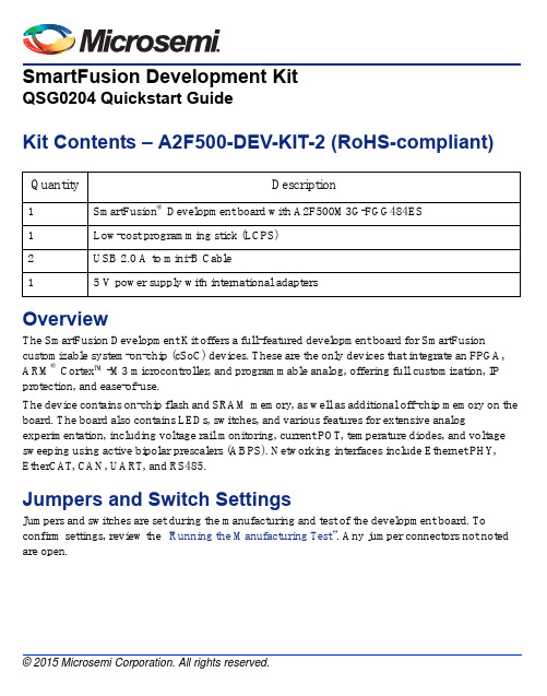
SmartFusion Development KitQSG0204 Quickstart GuideKit Contents – A2F500-DEV-KIT-2 (RoHS-compliant) Quantity Description1SmartFusion® Development board with A2F500M3G-FGG484ES1Low-cost programming stick (LCPS)2USB 2.0 A to mini-B Cable15V power supply with international adaptersOverviewThe SmartFusion Development Kit offers a full-featured development board for SmartFusion customizable system-on-chip (cSoC) devices. These are the only devices that integrate an FPGA, ARM® Cortex™-M3 microcontroller, and programmable analog, offering full customization, IP protection, and ease-of-use.The device contains on-chip flash and SRAM memory, as well as additional off-chip memory on the board. The board also contains LEDs, switches, and various features for extensive analog experimentation, including voltage rail monitoring, current POT, temperature diodes, and voltage sweeping using active bipolar prescalers (ABPS). Networking interfaces include Ethernet PHY, EtherCAT, CAN, UART, and RS485.Jumpers and Switch SettingsJumpers and switches are set during the manufacturing and test of the development board. To confirm settings, review the “Running the Manufacturing Test”. Any jumper connectors not noted are open.SmartFusion Development Kit Quickstart CardSW9 must be off (JTAGSEL = H) in order to program the SmartFusion device. SW9 remains in the off position for Libero ® software and SoftConsole programming.For a full description and location of all jumpers, refer to the SmartFusion Development Kit User’sGuide .Running the Manufacturing TestYou can run the manufacturing test to verify the device and board connections. The manufacturing test files are available from the SmartFusion Development Kit page. Instructions on how to run the test are available in the SmartFusion Development Kit User’s Guide .Connecting the BoardFollow the steps below to connect the board:1.Connect one of the USB cables from the PC to the USB connector on the board.2.Connect the LCPS to the PC via a USB cable.3.Connect the LCPS to the programming header on the board.4.Connect the 5 V power supply to the board.Factory DefaultFactory Default Factory DefaultJP1: 1–2 JP12: 1–2 JP21: 1–2 JP2: 1–2 JP13: 1–2 JP22: 2–3 JP4: 1–3; 7–9 JP14: 1–2 JP23: 1–2 JP5: 1–2; 3–4 JP15: 1–2 JP24: 1–2 JP6: 2–3JP16: 2–3 JP27: 1–2 J7: 2–3; 6–7; 10–11; 14–15 JP17: 2–3 JP28: 1-2 JP7: 1–2JP18: 1–2 J32: 1–2; 3–4; 5–6JP8: 3-4; 7-8; 11-12; 15-16 JP19: 2–3 –JP11: 1-2JP20: 1–2–SmartFusion Development Kit Quickstart CardSmartFusion Device JP16JP24A2F500Connector JTAG Chain Configuration Header (JP5)DB9 Connector for CAN0DB9 Connector for CAN1DIP SwitchRealView® HeaderJTAG_SEL Switch JP11, JP12JP7LCPSConnector DB9 Connector for RS485 (UART1)PUB Switch1.5 V Header (JP6)I2C Headers (J7)USB Connector for UART0JP22, JP23JP18Push-button SwitchesSPI Headers (JP8)J32DAC0 and DAC1Callibration POTSfor ± 15 V Bipolar OutputsJP13Mixed Signal HeaderDACOUT/ADC Headers (JP4)POT for Current Monitor JP14, JP15, JP21,JP27DirectCHeader (J13)RJ45 Connectors for EthernetCAT PortsJP30RJ45 Connectors for 10/100 Ethernet 10/100 Ethernet Board Reset Switch JP31JP20JP1, JP2Power Jack Power SwitchMemory DeviceConfiguration Headers (JP17, JP19)IGLOO PLUS HeaderJP28AGLP DIP SwitchPHYSmartFusion Development Kit Quickstart CardSoftware and LicensingThe SmartFusion Development Kit is supported by Libero® System-on-Chip (SoC) v10.0 or later, which includes a web install option. SoftConsole Software IDE and FlashPro are enabled by default in the web install; these software tools can be used for software design and debug. SmartFusion is also supported by Keil and IAR Systems, which can be installed separately. Refer to the SmartFusion Development Kit User’s Guide for more information.Software releases: /products/fpga-soc/design-resources/design-software/ libero-socKeil and IAR information: /soc/products/smartfusion/ecosystem.aspx Libero SoC v10.0 requires a valid Gold, Platinum, or Standalone Libero license.If you need a new license, select FREE Libero SoC Gold license and request a new one from your Microsemi Customer Portal account. This license supports all tools for designing with the SmartFusion family and associated development kits.License updates:/products/fpga-soc/design-resources/licensing Documentation ResourcesFor further kit information, including user's guide, tutorial, and full design examples, refer to the SmartFusion Evaluation Kit page:/products/fpga-soc/design-resources/dev-kits/smartfusion/smartfusion-development-kitTechnical Support and ContactsTechnical support is available online at /soc/support and by email at**********************.Microsemi SoC Sales offices, including Representatives and Distributors, are located worldwide. To find your local representative visit /soc/company/contact.。
AutoCAD性能提升指南说明书

AutoCAD TipsInstallation settings to speed up performance:1. Do not install VBA enabler (tremendously slows down performance)2. Enable Information System (2013 will not run without it when set up to communicate with AutoDesk 360)Initial commands to speed up performance (type the following at the command prompt):UCSDETECT (set to 0) – this will disable Dynamic UCSQPMODE (set to 0) – disables Quick Properties Palette for items selected in the drawingDRAWORDERCTL (set to 0) – speeds up regeneration when switching tilemodes and when regenerating in model space HPDLGMODE (set to 1) – displays hatch/gradient box for items selected in drawingHPQUICKPREVIEW (set to 0) – disables hatch previewVTENABLE (set to 0) – disables smooth view transitions when zooming in/out (makes zooming instantaneous) LAYERDLGMODE (set to 0) – speeds up loading of layers paletteMBUTTONPAN (set to 0) – middle button brings up snap menu, (set to 1) – middle button is PAN command ROLLOVERTIPS (set to 0) – disables rollover tipsSELECTIONPREVIEW (set to 0) – disables selection previewingSELECTIONCYCLING (set to 0) – turns selection cycling/overlapping offPICKADD (set to 1) – enables subsequent selections when modifying propertiesAUTOCOMPLETE – set to OFFLOCKUI (set to 0) – unlocks toolbars and windows (Note: when toolbars are locked, performance is better. Only use this command if you use the layers palette window in lieu of the layers toolbar.AUTOSNAP (set to 16) – Restricts F8 (ortho) from disabling F10 (polarmode)Initial settings to speed up performance:1. If your windows "Aero" theme is enabled, you need to disable it. Turn off Windows transparency also.2. Plug your mouse directly in to your laptop. Do not plug it in to the dock.2. Right click on your AutoCAD desktop icon and disable digital signatures.3. Type CONFIG at the command line and do the following:A. Under the display tab:- turn off scroll bars, status bar, tooltips, rollover tooltips. Shrink cursor size to speed up performanceB. Under open and save tab:- enable maintain visual fidelity and size compatibilityC. Under user preferences tab:- disable double click editing and shortcut menus in drawing areaD. Under drafting tab:- disable all auto track settings- under autosnap settings enable autosnap aperture boxE. Under selection tab:- disable object grouping and enable implied windowing- disable selection previewAutoCAD Tips(continued)Initial settings:1. Type DSETTINGS at the command prompt:-enable polar tracking (or press F10)- disable pointer input, enable dimension input where possible, click show only one dimension- disable quick properties palette- disable selection cycling2. Type 3DCONFIG at the command prompt:- enable adaptive degradation- click manual tune and enable hardware acceleration3. Pull down menus, go to:- Tools/Customize/Edit Program Parameters (ACAD.pgp) – for those of you that edit command abbreviations Commands to reduce drawing size and speed up performance:1. Type PURGE and AUDIT regularly, will remove errors, unused blocks, layers and trash files2. Type SCALELISTEDIT, will remove unused scales in the drawing3. Type –EXPORTTOAUTOCAD, Make sure all layers are on, thawed and unlocked before executing this command4. Type FLATSHOT will explode any 3D entities that are presentNote: For both of the below commands, select only small portions of the drawing at a time for this to be effective5. Type FLATTEN, will flatten any objects in the Z axis6. Type OVERKILL, will remove lines that are stacked on top of one anotherTo change the new offset command to the old one. If you use icons, modify your toolbar macro command to initiate "exoffset" instead of "offset". Or edit your PGP file to show the exoffset command.。
KDLayout使用指南

控件名称KDLayout类名com.kingdee.bos.ctrl.swing.KDLayout父类java.ObjectyoutManager2父接口相关的类布局约束类:KDLayout.Constraints功能列表通过为每一个控件添加一个停靠约束(Anchor),把设计时的绝对定位布局转化为可缩放的相对布局。
使用指南KDLayout是专门为UIDesigner设计布局管理器,通过对设计面板上的每一控件添加一个anchor属性,KDLayout就能将UIDesigner上绝对定位的布局变成可缩放的布局。
如果在UIDesigner外单独使用KDLayout,你需要填写更多的属性。
KDLayout布局属性KDLayout的内部类Constraints定义了在使用KDLayout时容器上每个控件必须填写的布局属性。
OriginalBound表示的是控件在UIDesigner上的原始大小Anchor表示的是控件的锚定方式。
锚定是指控件上的一边与父容器的同方向的一边或是中心点之间的固定关系。
当控件的锚定后,控件位置相对父容器固定。
当父容器大小改变后,控件与父容器之间的固定关系不变,控件的位置大小由父容器所决定。
在KDLayout中定义了五个锚定点、两种锚定方式,共九个锚定方式可选择。
不同锚定的方式用不同的常量表示,而且可以通过逻辑运算符“或”进行搭配使用。
:ANCHOR_TOP控件的上边与父容器的上边距离固定,等同于设计时距离:ANCHOR_BOTTOM控件的下边与父容器的下边距离固定,等同于设计时距离:ANCHOR_LEFT控件的左边与父容器的左边距离固定,等同于设计时距离ANCHOR_RIGHT :控件的右边与父容器的右边距离固定,等同于设计时距离ANCHOR_CENTRE :控件的中心点与父容器的中心点水平距离固定,等同于设计时距离:ANCHOR_TOP_SCALE控件的上边与父容器的上边距离固定,等同于设计时距离乘【父容器高度与设计时高度的缩放比】。
LAYOUT SKILL
目录PROTEL个人使用之经验谈 (1)各种版本PROTEL的常用快捷键 (2)protel 打印设置单片机 (3)PCB抄板密技 (4)PCB电路版图设计的常见问题 (5)PCB设计基本概念 (7)PCB设计几点体会 (9)Protel布线设计注意事项 (10)Protel常见技术问题答复 (11)将Protel原理图文件插入到Word文档中的方法 (19)PROTEL个人使用之经验谈1、在画原理图还是项目图前,A:对于元件的编号一定要有一套固定的用法。
比如电阻用r;电容用c;电感用l;这些命名方法一定要固定,并尽量在全公司成为一种规定。
B:对于项目图的编号,项目图(即上层电路)为page0;具体电路(即下层电路)定义从page1开始,并依次类推,这样的话编号就有这样的规则,第1页的电容为c101-c1xx; 第10页的电容为c1001-c10xx。
那你在画图过程中或调试过程中,只要根据元件编号和功能模块就可以很快的找到你所找的元件了,又节省时间,又为了以后的顺利生产埋下伏笔,何乐而不为呢?(不过这个主要适用于项目图较多的情况下,如果总共只有一张电路图,就没此必要了,画蛇添足吗?)2、在sch_---net---pcb的过渡过程中,千万不要偷懒,不然当你的pcb出来时就够你痛苦了,要查电路图找错误的时候你就会后悔莫及了,原理图、网络表、pcb一定要保持一致,每有一次修改,需按正常顺序,先修改原理图,再update网络表,然后再update你的pcb,绝对不要图一时之快,而省去上述步骤,直接修改pcb.笔者可是经过几次惨痛的教训得出的。
3、在编辑库文件时,元件一定要放在原点附近,尽量元件的第一pin放在原点上,不然用网络表生成的元件会飞的到处都是,而且pcb的文件会很大,gerber file也很难生成。
不过在这里如果出了问题,请使用快捷键,z—a,看元件是不是以最大的可能放打在pcb上(屏幕上),不然的话就是外围有track,或是有元件的comment或designator在外面.解决方法,等你出了问题,再来找我吧。
快速编程指南用户界面说明书

QUICK PROGRAMMING GUIDETable of ContentsUser Interface (1)Setting the Clock (3)Low Voltage Switch (4)Momentary (6)Maintained (7)Momentary Timed (8)Digital Switch (11)Activating Luma-net (14)Photocell Input (16)Scheduler Setup (20)Disable Switch Inputs (27)User InterfaceUSERINTERFACE These instructions were designed to assist the programmer with commonsetups.It makes the assumption all high and low voltage connections havebeen properly connected and confirmed.Since this is a condensed quick document you may see addtional selections insome menus.Don’t let this confuse you.Only concern yourself with the selec-tions in the instructions.Ok,here we go...The LCD display shows the current operational status of your relay panel andprovides a way to operate and configure your product.When the system is operating normally,the top line of the LCD display showsthe day,time,locked/unlocked status of the panel,and the status of the event scheduler.The second line shows the status of the panel:Normal,BypassON,Bypass OFF,or Emergency.User InterfaceProgramming/Function ButtonsAllows the user to navigate through the system configura-tion and setup menus.Selects or Saves the current menu item.Aborts the current entry and returns back one level in themenu structure.Clears the current entered value.Allows for direct front panel control of basic relay functions.Activates all relays in an override state.This operationtemporarily disables all switch inputs.Navigation ButtonsUse the keypad buttons for alpha-numeric data entry.The UP/DOWN buttons are also used for data entry/valuechanges and to navigate menus.The LEFT/RIGHT buttons are also used to changedbetween“fields”when configuring your panel.NOTE After approximately3minutes of inactivity on any menu screen, the LCD will revert back to the status screen.User Interface USER INTERFACE Setting the ClockStep 1:Press Step 2:Press to:Step 3:PressStep 4:Press to:Step 5:PressStep 6:Display should read:Step 7:Use and data entry buttons to adjustall settings.Step 8:Press to save your settings.NOTE For astronomical settings,contact the factory at (800)959-6004.The following behaviors are available for programming low voltage switches:1-Momentary:first switch press is on,second switch press is off.2-Maintained (SPST):typically a standard wall switch;when the switch is closed,the relays will turn on and when the switch is opened the lights will turn off.3-Momentary Timed:when switch is pressed,lights on for a specified time period.Step 1:Press Step 2:Press to:Step 3:Press Step 4:Press to:Step 5:Press Step 6:Press to:Step 7:Press Step 8:Display should read:Step 9:Press to:Step 10:Press Step 11:Press to:Step 12:Press Step 13:Press to:Step 14:PressLow Voltage SwitchS WI TC HLow Voltage Switch Step15:Display should read:NOTE Use to select desired switch input.Switch inputs are the hardwired locations within the panel.For instance,aZ-MAX8panel has8switch inputs;therefore,001is the first inputand008is the eighth input.We will use switch input001for thisexample.Step16:PressTo program a Momentary Low Voltage Switch,proceed to Step17a on page6.To program a Maintained Low Voltage Switch,proceed to Step17b on page7.To program a Momentary Timed Low Voltage Switch,proceedto page8.LOW VOLTAGE SWITCHStep 17a:Press to:Step 18:Press Step 19:Press to:Step 20:Press Step 21:Press to relay selection section;the left hand side of 01-01should be flashing.Step 22:Use to select desired relays.Ex.Step 23:Press Step 24:To add additional relays,repeat Steps 19thru 23.Ex.If no additional relays are required,press Cancel.To proceed to additional input configurations,repeat Steps 15thru 23.Step 25:Press to exit.Low Voltage Switch |Momentary S WI TC HLow Voltage Switch|Maintained Step17b:Press to:Step18:PressStep19:Press to:Step20:PressStep21:Press to relay selection section;the left hand side of01-01should be flashing.Step22:Use to select desired relays.Ex.Step23:PressStep24:To add additional relays,repeat Steps19thru23.Ex.If no additional relays are required,press Cancel.To proceed toadditional input configurations,repeat Steps15thru23.Step25:Press to exit.LOW VOLTAGE SWITCHA timed switch could be used when there is not an occupancy sensor in the area but you want to make sure the lights don’t remain on over a determined period of time.NOTE You will be required to go through two processes:A.Setting up the switch TYPE,action and relays to be controlled.B.Assigning a time to the action.Process A:Setting up the switch,action and relays to be controlled.Step 1:Press Step 2:Press to:Step 3:PressStep 4:Press to:Step 5:PressStep 6:Press to:Step 7:PressStep 8:Display should read:Step 9:Press to:Step 10:PressStep 11:Press to:Step 12:PressStep 13:Press to:Step 14:Display should read:Low Voltage Switch |Momentary Timed S WI TC HNOTE Use to select desired switch input.Switch inputs are the hardwired locations within the panel.For instance,aZ-MAX8panel has8switch inputs;therefore,001is the first inputand008is the eighth input.We will use switch input001for thisexample.Step15:PressStep16:Press to:Step17:PressStep18:Press to:Step19:PressStep20:Press to relay selection section;the left hand side of01-01should be flashing.Step21:Use to select desired relays.Ex.Step22:PressStep23:To add addtional relays,repeat Steps14thru22.Ex.If no additional relays are required,press Cancel.To proceed toadditional input configurations,repeat Steps14thru22.LOW VOLTAGE SWITCHProcess B:Now we will assign a hold time to the swtich alone.This is the amount of time the switch will remain active before deactivating and thus shutting the lights off.Step 1:Press Step 2:Press to:Step 3:Press Step 4:Press to:Step 5:PressStep 6:Press to:Step 7:PressStep 8:Press to:Step 9:Press to edit the time.Step 10:Use to change the time.Step 11:Press to go back to the main screen.NOTE The time you set is a global time and applies to all timed switches.S WI TC HDigital Switch|Momentary The following behaviors are available for programming digital switches: 1-Momentary:first switch press is on,second switch press is off.2-Maintained(SPST):typically a standard wall switch;when the switch is closed,the relays will turn on and when the switch is opened the lightswill turn off.3-Momentary Timed:when switch is pressed,lights on for a specified time period.NOTE This section will only cover momentary switch functions.There are two types of swtiches-low voltage and digital.Low voltage switch inputs are local to the panel with48maximum inputs available(1-48).For this discussion,you will begin assigning digital switches beginning at49thru252. Since digital switches have address switches you will be required to add: 1-Input#2-Station#3-Button#4-Refer to Activating Luma-Net starting on page16Step1:PressStep2:Press to: Step3:PressStep4:Press to: Step5:PressStep6:Press to: Step7:PressStep8:Display should read: Step9:Press to: Step10:Press to:DIGITAL SWITCHDigital Switch|MomentaryStep 11:PresStep12:Use the numeric keypad to enter“049”for the first digital switch.Ex.Step13:Press twice.Step14:Use the numeric keypad to enter the digital switch address.Ex.Step15:Press once to enter digital switch button.Ex.Step16:PressStep17:For additional inputs or buttons,press the up arrow to“050”for switch input.Repeat Steps9thru12for any additional switches or buttons.Otherwise,proceed to Step14.EXAMPLE1:5Button StationINPUT:049INPUT:050INPUT:051INPUT:052INPUT:053Digital Switch|Momentary OREXAMPLE2:3Single Button StationsINPUT:049INPUT:050INPUT:051Step18:PressStep19:Press to:Step20:PressStep21:Press to:Step22:PressStep23:Use the numeric keypad to select the desired switch input.Ex.Step24:PressStep25:Press to:Step26:PressStep27:Press to:Step28:Press DIGITAL SWITCHDigital Switch|MomentaryStep29:Press to relay selection section;the left hand side of01-01should be flashing.Step30:Use to select desired relays.Ex.Step31:PressStep32:To add additional relays,repeat Steps27thru31.Ex.If no additional relays are required,press Cancel.To proceed toadditional input configurations,repeat Steps23thru31.Step33:Press once to go back to the main screen.Step34:The final step for completing this process will be to activateLuma-net.Refer to Activating Luma-net below.Activating Luma-netStep1:PressStep2:Press to:Step3:PressStep4:Press to:Step5:PressStep6:Press to:Step7:PressDigital Switch|Activating Luma-net Step8:Display should read:Step9:Press to:Step10:PressStep11:Press to:Step12:PressStep13:Press to:Step14:PressStep15:Press to:Step16:PressStep17:Press to:Step18:PressStep19:Press to:Step20:PressNOTE The System ID#cannot be equal to a Station ID#.Voltage Selection:For24or48relay panels,install jumper JP5to24V.For8relay panels,install jumper JP10to24V.DIGITAL SWITCHPhotocell InputPhotocell Input Step1:PressStep2:Press to:Step3:PressStep4:Press to:Step5:PressStep6:Press to:Step7:PressStep8:Display should read:Step9:Press twice to:Step10:PressStep11:Press to:Step12:PressStep13:Press to:PHOTOCELL INPUT Step14:PressStep15:Choose desired input for photocell.Ex.Step16:PressStep17:Use to:Step 18:Press to:Step 19:Use to change the “N”to “Y”.Ex.Step 20:Press to:Step 21:Press to:Step 22:Press to:Step 23:Press to:Step 24:Press Step 25:Press to:Step 26:Press to:Step 27:Press to:Step 28:Press Step 29:Press to choose one of the following:1REL ON-FOR OFF Wall switch turns on and photocell turns lights off.2FOR ON-FOR OFFPhotocell turns lights on and lights off.3FOR ON-REL OFFPhotocell turns lights on and wall switch turns lights off.Ex.Photocell InputI NP U TPhotocell InputStep30:PressStep31:Change delay setting,if needed.Ex.Step32:PressStep33:Press so the“N/A”for“ON”is flashing.Ex.Step34:Use the numerical keys to enter the desired foot-candle value forthe lights to be triggered on.Step35:Press so the“N/A”for“OFF”is flashing.Step36:Use the numerical keys to enter the desired foot-candle value forthe lights to be triggered off.Step37:Press to:Step38:PressStep39:Press to relay selection section;the left hand sideof01-01should be flashing.PHOTOCELL INPUT Step40:Use to select desired relays.Ex.Step41:PressStep42:To add additional relays,repeat Steps37thru41.Ex.You will need to understand the items listed below before starting the procedure.Actions:Actions define what is going to happen.The things that are going to happen are called Action Items.You will be required to enter the following information:1.Action Name 2.Action Items Action Items:1.Relay ON or OFF 2.Groups ON or OFF 3.Blink Warn Override (BWO)Events:Events establish the time when Actions are supposed to happen.You will be required to enter the following event information:1.Event Name 2.Event Time Creating Actions and Action Items:The example below will walk you through creating a lights on and off action.Step 1:Press Step 2:Press to:Step 3:Press Step 4:Press to:(If the display reads MODE:ADVANCED ,proceed to Step 9.)Step 5:Press Step 6:Press to:Step 7:Press Step 8:Display should read:Scheduler Setup |Creating Actions S ET U PScheduler Setup|Creating Actions Step9:Press twice.Step10:Press to:Step11:PressStep12:Press to:Step13:Press twice.(ACT1should be flashing.)Step14:Name the Action:ON.NOTE You can change the name using the right and left arrow buttons tomove the cursor and the up or down arrow buttons to change thecharacter.You can also use the alpha-numeric keypad to entercharacters.Tapping the alpha-numeric button the first time willresult in the number,tapping the same button again will result inthe character listed above the number on the button.In the case of the1and0buttons,a hyphen or space characterwill be displayed respectively.In the case of the number keys2-9,the left most character will be displayed.For these keys,as theyare pressed repeatedly,each successive character,from left toright is displayed until all have been displayed,at which time itwraps back to the number and repeats.Step15:Press when you have finished naming the Action.Step16:Press to:Step17:PressStep18:Press once,then use the arrow keys to set theappropriate range of relays to be controlled by the Action. Ex.SCHEDULER SETUPStep 19:Press Step 20:If you need to add a second group of relays to turn on,repeat Steps 15thru 18.Otherwise,proceed to Step 21.Step 21:Press Step 22:Press to:Step 23:Press Step 24:Press to:Step 25:Press Step 26:Name the Action:OFF .Step 27:Press Step 28:Press to:Step 29:Press Step 30:Press once and then use the arrow keys to set the appropriate range of relays to be controlled by the Action.Ex.Step 31:Press once and then use the up or down arrow keys to choose the OFF command Step 32:Press Step 33:If you need to add a second group of relays to turn off,repeat Scheduler Setup |Creating Actions S ET U P Steps 27thru 31.Otherwise,proceed to Creating Events .Scheduler Setup|Creating Events Step1:Press to:Step2:Press to:Step3:PressStep4:Press to:Step5:PressStep6:Enter the event time.Ex.Step7:PressStep8:Choose the days of the week that the event is to be active on.Ex.If the day of the week is capitalized,then the event will be activeon that specific day.Step9:PressStep10:Use to choose the appropriate action for theevent.Ex.Step11:PressStep12:Use to choose if this event is to be a single event(only happens once).Ex.SCHEDULER SETUPStep 13:Press Step 14:Use to choose if this event is to be a single event (only happens once).Ex.NOTE Default sweep count time is 60minutes;see manual for further information on sweep count or contact our technical support staff at (800)959-6004.Step 15:Press Step 16:Press to:Step 17:Press Step 18:Enter the event time.Ex.Step 19:Press Step 20:Choose the days of the week that the event is to be active on.Ex.If the day of the week is capitalized,then the event will be active on that specific day.Step 21:Use Step 22:Use to choose the appropriate action for the event.Ex.Scheduler Setup |Creating Events S ET U P Step 23:PressScheduler Setup|Creating Events Step43:Use to choose if this event is to be a single event.Ex.Step25:PressStep26:Use to choose a sweep count;or leave as000ifno sweep count is needed.Ex.Step27:PressStep28:PressSCHEDULER SETUPStep 1:Press Step 2:Press to:Step 3:Press Step 4:Press to:Step 5:Press Step 6:Change the current time to one minute before the ON event is to happen.Step 7:Press Step 8:Please wait one minute and when the scheduled event time comes up,the selected relays should come on.Step 9:Press Step 10:Press to:Step 11:Press Step 12:Press to:Step 13:Press Step 14:Change the current time to one minute before the OFF event is to happen.Step 15:Please wait the one minute and when the scheduled event time comes up,the selected relays should go off.Scheduler Setup |Testing Events S ET U PIn some cases,the customer may desire to disable a switch,photocell,oroccupancy sensor during certain times of the day.The below instructionsoutline how to set up this scenario.Step1:PressStep2:Press to:Step3:PressStep4:Press to:(If the display reads MODE:ADVANCED,proceed to Step9.)Step5:PressStep6:Press to:Step7:PressStep8:Display should read:Step9:Press twice.Step10:Press to:Step11:PressStep12:Press to:Step13:Press twice.Step14:Name the Action:ON.SCHEDULER SETUPNOTE You can change the name using the right and left arrow buttons to move the cursor and the up or down arrow buttons to change the character.You can also use the alpha-numeric keypad to enter characters.Tapping the alpha-numeric button the first time will result in the number,tapping the same button again will result in the character listed above the number on the button.In the case of the 1and 0buttons,a hyphen or space character will be displayed respectively.In the case of the number keys 2-9,the left most character will be displayed.For these keys,as they are pressed repeatedly,each successive character,from left to right is displayed until all have been displayed,at which time it wraps back to the number and repeats.Step 15:Press Step 16:Press to:Step 17:Press Step 18:Press once and then use the arrow keys to set the appropriate range of relays to be controlled by the Action.Ex.Step 19:Press once and then use the up or down arrow keys to choose the ON command.Step 20:Press once and then use the numerical keys to set the priority level to 7.This allows the scheduler to turn the relays on at one priority level higher than the default of 8.NOTE The switch inputs default priority is 8.See manual for further information on priorities.Step 21:PressS ET U PStep22:If you need to add additional relays to turn on,repeat Steps15thru21.Otherwise,proceed to Step23.Step23:Press back to:Step24:PressStep25:Press to:Step26:PressStep27:Name the Action:OFF.Step28:PressStep29:Press to:Step30:PressStep31:Press once and then use the arrow keys to set theappropriate range of relays to be controlled by the Action.Ex.Step32:Press once and then use the up or down arrowkeys to choose the REL(RELINQUISH)command.Step33:Press once and then use the numerical keys to setthe priority level to7.This allows the scheduler to relinquish con-trol of the relays back to priority level8.NOTE The switch inputs default priority is8.See manual for further information on priorities.SCHEDULER SETUPStep 34:PressProceed to Creating Events if Blink Warn command is NOT required.Step 35:Press to:Step 36:Press once and then use the arrow keys to set the appropriate range of relays to be controlled by the Action.Step 37:Press once and then use the up or down arrow keys to choose the BWO (BLINK WARN ON)command.Ex.Step 38:Press Step 39:If you need to add additional relays to REL,repeat Steps 29thru 33.Otherwise,proceed to Creating Events.S ET U PDisable Switch Inputs|Creating Events Step1:Press twice to:Step2:Press to:Step3:PressStep4:Press to:Step5:PressStep6:Enter the Event time.Ex.Step7:PressStep8:Choose the days of the week that the event is to be active on.Ex.If the day of the week is capitalized,then the event will be activeon that specific day.Step9:PressStep10:Use to choose the appropriate action for theevent.Ex.Step11:PressStep12:Use to choose if this event is to be a single event.Ex.SCHEDULER SETUPStep 13:Press Step 14:Use to choose a sweep count,or leave as 000if no sweep count is needed.Ex.Default sweep count time is 60minutes;see manual for further information on sweep count.Step 15:Press Step 16:Press to add a second event.Step 17:Enter the Event time.Ex.Step 18:Press Step 19:Choose the days of the week that the event is to be active on.Ex.If the day of the week is capitalized,then the event will be active on that specific day.Step 20:Press Step 21:Use to choose the approriate action for the event.Ex.Step 22:PressDisable Switch Inputs |Creating Events S ET U PDisable Switch Inputs|Creating Events Step23:Use to choose if the event is to be a single event.Ex.Step24:PressStep25:Use to choose a sweep count;or leave as000ifno sweep count is needed.Ex.Step26:PressStep27:PressSCHEDULER SETUPStep 1:Press Step 2:Press to:Step 3:Press Step 4:Press to:Step 5:Press Step 6:Change the current tme to one minute before the ON event is to happen.Step 7:Press Step 8:Please wait one minute and when the scheduled event time comes up,the selected relays should come on.Step 9:Press Step 10:Press to:Step 11:Press Step 12:Press to:Step 13:Press Step 14:Change the current tme to one minute before the OFF event is to happen.Step 15:Please wait the one minute and when the scheduled time comes up,the selected relays should go off.Disable Switch Inputs |Testing Events S ET U PLeviton Manufacturing Co.,Inc.,Lighting Management Systems Division 20497SW Teton Ave.,Tualatin,OR97062-8812USAPO Box2210,Tualatin,OR97062USAUS Customer Service:(800)736-6682Fax:(503)404-5594US Tech Support:(800)959-6004Visit our website at:/LMS。
Layout(集成电路版图)注意事项及技巧总结

Layout主要工作注意事项●画之前的准备工作●与电路设计者的沟通●Layout 的金属线尤其是电源线、地线●保护环●衬底噪声●管子的匹配精度一、l ayout 之前的准备工作1、先估算芯片面积先分别计算各个电路模块的面积,然后再加上模块之间走线以及端口引出等的面积,即得到芯片总的面积。
2、Top-Down 设计流程先根据电路规模对版图进行整体布局,整体布局包括:主要单元的大小形状以及位置安排;电源和地线的布局;输入输出引脚的放置等;统计整个芯片的引脚个数,包括测试点也要确定好,严格确定每个模块的引脚属性,位置。
3、模块的方向应该与信号的流向一致每个模块一定按照确定好的引脚位置引出之间的连线4、保证主信号通道简单流畅,连线尽量短,少拐弯等。
5、不同模块的电源,地线分开,以防干扰,电源线的寄生电阻尽可能较小,避免各模块的电源电压不一致。
6、尽可能把电容电阻和大管子放在侧旁,利于提高电路的抗干扰能力。
二、与电路设计者的沟通搞清楚电路的结构和工作原理明确电路设计中对版图有特殊要求的地方包含内容:(1)确保金属线的宽度和引线孔的数目能够满足要求(各通路在典型情况和最坏情况的大小)尤其是电源线盒地线。
(2)差分对管,有源负载,电流镜,电容阵列等要求匹配良好的子模块。
(3)电路中MOS管,电阻电容对精度的要求。
(4)易受干扰的电压传输线,高频信号传输线。
三、layout 的金属线尤其是电源线,地线1、根据电路在最坏情况下的电流值来确定金属线的宽度以及接触孔的排列方式和数目,以避免电迁移。
电迁移效应:是指当传输电流过大时,电子碰撞金属原子,导致原子移位而使金属断线。
在接触孔周围,电流比较集中,电迁移更容易产生。
2、避免天线效应长金属(面积较大的金属)在刻蚀的时候,会吸引大量的电荷,这时如果该金属与管子栅相连,可能会在栅极形成高压,影响栅养化层质量,降低电路的可靠性和寿命。
解决方案:(1)插一个金属跳线来消除(在低层金属上的天线效应可以通过在顶层金属层插入短的跳线来消除)。
cad设计院实用干货图层快键件设定

1, *layoff2, *layon3, *layiso4, *laylck5, *layulk6, *sketch把这些复制到:工具>自定义>编辑程序参数(acad.pgp),格式参照文本中已有的格式。
保存关闭,重启CAD,如果你操作无误。
按“3”然后选择一个目标就可以隔离出目标所在的图层。
剩下的分别是,1-关闭目标图层,2-开启所有图层,4-锁定,5-解锁,6-手绘线步骤如下:依次找CAD工具菜单,自定义,编辑程序参数(acad.pgp)然后就打开了一个PGP文件。
然后添加下面的内容:(汉字部分是我加的解释,不要带进去。
另外,最前面的大写字母,是我定义的内容,你可以根据自己的习惯自己选其他字母或字母组合,因为LAYER首字母L在右手区,所以我尽量用图层首字母T字开头,后加一个字母,仅供参考)DQ, *ai_molc 将对象图层置为当前。
DQ,就是当前喽。
TC, *LAYER 图层对话框。
图层首字母。
TTC, *layerp 上一个图层状态。
多加了一个T,和上面的命令区别开TCC, *copytolayer 将图对象复制到XX图层,选好对象后,空格,会出一个对话框,TD, *layon 图层打开TF, *layoff 图层关闭TG, *layiso 将对象所在图层孤立出来,即,关闭除对象图层外的所有图层。
支持多选。
TS, *laylck 图层锁定TSS, *layulk 图层解锁,多加了个S,和上面的区别开。
TTh, *laymrg 图层合并,具体用法我不记得了。
呵呵。
只是当时定义了一下。
TZ, *layfrz 图层冻住。
TZZ, *LAYTHW 图层解冻Tq, *LAYCUR 将所选对象移动到当前图层。
注意与DQ命令区别开Tv, *LAYMCH 将对象移动到XX图层,与TTC类似。
只是TTC是复制,这个是移动。
注意:1。
要装上EXPRESS TOOLS,就是传说中的快车工具,才可以的。
Herospeed XVR Kits Quick Start Guide

Please read the Quick Start Guide carefully before using the product and keep it. Related tools and documents of products, please download from .StatementThank you for purchasing our products, if you have any questions or requires, please contact us.This Guidelines adapt for XVR and HD cameras in the kits.It will be updated subject to product’s updating; new version will be not noticed specifically. If this manual’s any products description not accord with the real products, please in kind prevail.Safety Precautions1. After the equipment is arranged, please timely modify the default user password to prevent theft.2. Please do not place the equipment and installed in direct sunlight or near the heating equipment.3. Please do not install the equipment in a wet, dusty or soot place.4. This equipment should be kept horizontal during installation and avoid installing in locations subjectto excessive vibration. Pay attention to prevent the product fall.5. Do not drop or splash the liquid on the equipment, and ensure that the equipment can not be placed on the liquid filled items to prevent the flow of liquid into the device.6. Please install in a well-ventilated place, do not plug the ventilation of the device.7. Please use the equipment in the rated input and output range.8. Please do not arbitrarily disassemble the equipment.9. Please transport, use and store the equipment in the permissible humidity and temperature range. DisclaimerThe following responsibilities are exempt or restricted, please pay special attention to:1. Our Company shall not be liable to you or any person for personal injury or property damage forany of the following reasons, and shall not responsible for the incorrect installation or use not in accordance with the requirements ; for the purpose of safeguarding the State or the public interest; force majeure; Y our own or third party reasons (including but not limited to the use of third party products, software or components and other issues).2. Our company has not been in any express or implied way to ensure that this product is suitable for special purpose or use, this product shall not be used for medical / safety equipment or other product failure may lead to life-threatening or personal injury applications and mass destruction Weapons, biological and chemical weapons, nuclear explosions or any unsafe use of nuclear energy and other dangerous or contrary to humanitarian use. Any loss or liability arising from such use will be at yourown expense.3. Products under the correct installation and use can be aware of a specific occurrence of illegal intrusion, but can not avoid the accident or the resulting personal injury or property damage. In daily life please be vigilant and strengthen your awareness of safety.4. The Company is not responsible for any indirect, incidental, special or punitive damages, requests, loss of property or loss of any data or documents. T o the maximum extent permitted by law, our liability does not exceed the amount paid by you when you purchase this product.XVR Kits is convenient for installation via easy plug & use, no need any set up.Start the installation guide step into:Step 1: Installation PreparationInstall XVR hard drive. Make sure all power is turned off before installing.Installation tools: Cross screwdriver (Please use the professional hard disk recommended by supplier). XVR rear panel interface description:BNC Video input, CVBS Video output, Audio output, VGA Video output interface, HD video output interface, Audio input, Ethernet port, USB2.0 port, RS485 connection PTZ, power input, as below:Analog camera interface Description: power input interface, BNC video output interface, as below:(1) Unscrew the four fixed screws on the baseplate and remove the upper cover.(2) Fix the HDD on the bottom panel with screws.(3)Connect the HDD power cable and data cablebetween PCB board and HDD.(4) Fix the upper cover with screws.Note: The picture is for reference only, the final product to prevail in kindNote s: Image for instruction use only, the final goods are subjected to the real object. XVR Kits Quick Installation GuideNote: The picture is for reference only, the final product to prevail in kindNote: The picture is for reference only, the final product to prevail in kindStep 3: Make sure XVR kit working well:Connected the XVR with the display, HD camera access XVR via the BNC, XVR and the camera plug in the power supply, without any operation, because it has been configured successfully before the factory, when the display appears on the analog camera video.Note: The product configuration power adapter voltage is 12V , please ensure that the power supply (100V ~ 240V) normal, not below or above the power supply range, otherwise the device will get seriously damaged.Step 2: Device ConnectionUse the 5ch power cable splitter to connect with the power supply, and another end connect with XVR recorder and the HD camera power supply. XVR recorder will preview the screen via the BNCcable. default (XVR address: //192.168.1.88), the connect way as below:12V/5AInternet picture transmissionStart up the XVR, right click the desktop and enter the user login interface. Input the user name and password, click " Login ".System default user name : "admin " password : "12345".Enter preview interface after device start up. Preview interface include date and time of system,and channel name. Login system, double left click to switch between full screen and multi-screen.Menu Basic Operation Instructions1) Enter menu modeLogin system,right click to popup shortcut menu.Left click [menu], enter the main menu interface.Left click [playback], enter playback operation interface.Left click [record setup], enter record setting operation interface.2) Exit menu modeRight click to exit menu mode.In the menu mode, right click to return to the previous menu (also for othermenus).Click the right mouse button pop-up shortcut menu, shortcut menu consists of the followingthree parts:Preview mode: Select the preview mode in the menu bar you like.Shortcut menu mode: It contains 【Poll】, 【Record】, 【Add Camera】 , 【XVR image】, you can click and the enter corresponding menu directly.Main menu : It contains 【Playback】,【Export】,【HDD】,【Record】,【Camera】,【Configuration】,【Maintenance】,【Shutdown】eight parts.1、HDD formatting. Make sure that the hard disk is detected and works well. (Y ou can check status of HDD from menu “HDD”-”General”).2、Enter “Record“ interface to set recording from shortcut menu “Record“ or main menu “Record“.Default setting is all channels are recorded 24 hours a day.Recording SettingShortcut Menu Introduction3、Motion Detection Setting. Enable “Motion” to activate motion recording, motion sections have no more than 6 times each day. If the setting of manual record and motion record are overlapped, it can only save the motion records while motion detection comes up.Enter “Playback” interface by clicking “Playback” from shortcut or main menu, select channels andsearch the record files and playback what you want.Or(Video Playback Interface)Menu InterfaceShortcut MenuXVR kits default match cameras device, connect all the devices to XVR, power on, connect the monitor device, then can real time preview. Left click 【1-Win】/【4-Win】in the menu, and enter real time view interface, can add one or more cameras monitor Win at the same time.PC Side LAN AccessXVR LAN login (the PC and the device are in the same router)① Make sure the recorder and the connected computer are in the same segment. If not, pleasse set IP address of your PC (computer) the same segment as the XVR’s, for example: ‘192.168.1.33, but it must be different IP as the XVR’s. (XVR default IP address is 192.168.1.88).② Open IE browser, choose T ool- internet item-safe-default level-ActiveX Controls and plug-ins, All choose start using.③ Open "Search T ool", double-click the target device from the search result to enter the login interface, or open the IE browser to enter the XVR address: such as http://192.168.1.88/ (If the port 80 of the XVR is changed to other, you need to add the changed port) to enter the login interface. ④ Login XVR: Enter the username and password and click “Login”(Notes: Default user: ”admin”, password: ”12345”).⑤ Preview XVR through PC:Click ”play” button in the bottom interface of ‘LiveVideo’.Search T oolMobile App AccessStep 1: Download and install BitVision on smart phone by following way:1. In the Android phone App Store or iPhone App Store enter “BitVision” search, download and install.2. Scan the following QR codes to download and install the App.Step 2: Account loginOpen BitVision App, click " " of the sliding sidebar to enter the login interface, enter the account number , password, and then click "Login" (New user please register an account).Step 3: Add a deviceIn the sliding menu, click "Device manage" → click " " → click " Add device "→ click "SN Add" → Scan the QR Code printed on the device sticker or posted on the P2P interface →Enter device user name, password and Captcha (printed on the label), click "Submit" →Click "Please set the device name ", enter the device name, click "Done "; Click "Please choose a group ", choose camera group, click "Finish".Step 4: Live previewIn the main interface, select "Real time", click the " " to enter the “Device manage” interface, choose the device channel you want to preview, click "Done".Start to play the real-time video.Android App QR iOS App QR3. Download from the following websites:Android App: https:///store/apps/details?id=com.gzch.lsplat.bitdog iOS App: https:///app/id1419463554。
layout常用基本操作

进入virtuoso编辑器:icfb& (注意,请进入到项目layout所在的路径下再启动icfb&):top222/layout 新建一个layout:file->new cell->在view里选择‘virtuoso’,并填入cell名显示所有层:shift+f 显示顶层:ctrl+f 全屏显示:f进入下一层:shift+x 回到上一层:shift+b 显示某层属性:t放大:右键、ctrl+z 缩小:shift+z 退出命令:Esc(一次退出一个命令)常用命令:打标尺:k 去标尺:shift+k 全选:ctrl+a 全不选:ctrl+d复制〔copy〕:c(先选中要复制的图形->c->在合适位置点一下->在新位置单击结束)移动〔move〕:m(同上)旋转:右键单击矩形〔rectangle〕:r(单击左键确定第一个顶点,再单击确定其对角顶点,注意勿拖拽鼠标)修改边长〔stretch〕:s(也可用于移动整个图形、或者一个角)删除:delete 返回上一步〔undo〕:u(默认只能返回一步,可系统设置为返回1~10步)多边形〔polygen〕:shift+p(每点一次确定一个顶点,双击完成)通道连线〔path〕:p 选择多个:按shift点左键取消选择:按ctrl点左键部分/全部选择:F4 合并图元〔merge〕:shift+m(该步骤只在版图所有工作完成后进行)挖槽〔chop〕:shift+c(先要选中原图形)重力吸附开关〔gravity〕:g(或shift+e调出对话框再点击gravity on)display option:e (其中可以设置x\y方向的最小步长、采用正交或任意方向进行操作等)调用元胞〔instance〕:i(可以直接填入需要调用的阵列大小)注意,要求所有器件均调用元胞查看属性:q(也可在其中更改图元或元胞阵列属性)如:copy与move的镜像、阵列大小&间距;path的宽度等。
kuboard 操作手册

kuboard 操作手册Kuboard是一个开源的Kubernetes集群管理平台,提供了可视化的界面来管理Kubernetes集群。
以下是Kuboard的基本操作手册:1. 安装和配置:在Kubernetes集群上安装Kuboard,可以参考Kuboard的官方文档进行安装和配置。
配置Kuboard所需的资源,例如身份验证、授权、存储等。
2. 登录Kuboard:使用管理员账户登录Kuboard。
在登录后,可以看到Kuboard的主界面,其中包含了集群的概览、节点、部署、服务、网络等各个方面的信息。
3. 管理集群:在集群概览页面,可以查看集群的状态、节点信息、资源使用情况等。
在节点页面,可以查看节点的状态、运行的应用、资源使用情况等,并对节点进行管理。
在部署页面,可以查看和管理集群中的部署,包括镜像、配置、日志等。
在服务页面,可以查看和管理集群中的服务,包括端口、负载均衡等。
在网络页面,可以查看和管理集群的网络,包括IP地址、路由等。
4. 权限管理:在权限管理页面,可以设置不同角色的权限,例如管理员、开发者等。
为不同用户分配不同的角色,控制其对集群的访问权限。
5. 监控和日志:在监控页面,可以查看集群的性能指标、日志等。
在日志页面,可以查看各个组件的日志,帮助排查问题。
6. 升级和卸载:当Kuboard需要升级时,可以参考官方文档进行升级操作。
当不再需要Kuboard时,可以参考官方文档进行卸载操作。
以上是Kuboard的基本操作手册,具体操作可能会根据版本和实际情况有所不同,建议参考官方文档进行操作。
QuickStartGuide
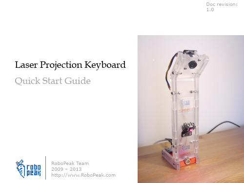
Initial Calibration
• Basic calibration process
Power-on Check
Connect with the software(driver)
Tuning the parts(optional) Keyboard Calibration
Power-on Check
Done!
• Your laser projection keyboard should work like a normal keyboard after you finished the previous steps in most cases. • If you feel something wrong, please refer to the more detailed Calibration and Use manual for helps.
LaserProjectionKeyboardKit-calibration_and_use
Basic Process of the Kit
You need to assemble and calibrate the kit first to make the kit work. Enjoy the process of DIY
• The kit requires the related signal processing software designed by RoboPeak to work. Please run this software. • The software supports both Windows and MacOS
– The direction and heading of the linear laser – The focus of the IR camera
Layout命令应用技巧(培训)
Layout命令应用技巧(培训)在编排页面和布局内容方面,Layout命令是一种非常有用的工具。
它允许用户创建复杂和吸引人的页面布局,并能够以专业和一致的方式展示内容。
以下是一些使用Layout命令的技巧,可以帮助您在培训材料中创建出色的页面设计。
1. 使用网格和栅格系统:网格和栅格系统是Layout命令的核心组成部分,可以帮助您将页面分割为等大的列和行。
这样,您可以更容易地对齐和布局内容。
例如,在一个内容页中,您可以将其分为两列,左侧用于标题和正文,右侧用于图片或其他相关信息。
使用栅格的好处是可以确保页面保持一致和平衡的外观,同时可以更容易地改变布局和重新排列内容。
2.使用固定和自适应布局:固定布局指定了页面元素的确切位置和大小。
这在希望控制布局的情况下非常有用,比如在固定的幻灯片和布局中。
另一方面,自适应布局允许页面根据屏幕或窗口的大小自动调整内容的大小和位置。
这对于可以在不同设备上查看的培训材料非常重要,以确保内容始终呈现出人性化的外观。
3. 利用样式和模板:Layout命令还允许用户创建和使用样式和模板。
样式是为特定类型的内容创建的预定义格式,比如标题、段落或列表的样式。
而模板是一种预定义的布局,可以在不同页面和篇章中使用,以确保一致的外观和样式。
使用样式和模板可以提高页面设计的效率,并确保材料的一致性。
4. 添加背景和边框:除了基本的页面布局之外,Layout命令还允许用户为页面添加背景和边框。
背景可以是纯色、渐变色或图像,可以为页面添加专业和吸引人的外观。
边框可以用来强调页面的内容或创建不同部分之间的分隔线。
通过使用背景和边框,您可以增强材料的可视吸引力,并帮助读者更好地理解和记忆所呈现的信息。
5. 使用间距和对齐:在设计布局时,控制页面元素之间的间距和对齐是至关重要的。
Layout命令允许您调整元素的间距和对齐方式,以确保页面看起来整洁和协调。
在创建培训材料时,确保标题、段落、列表等元素之间的间距适当且一致,以提高可读性和可视外观。
杰尼奥 Gimbal 快速入门指南说明书

V-Lock with IDX E-7S battery. AB mount with Dionic 90 (1.7 lbs).
Pilot™ Backpack
(With integrated MERLIN storage pocket.)
Included accessories
T-handle allen wrench, 2.1mm DC power cable, RCA video cable, BNC to RCA adaptor, camera mounting screw and anti-rotation pin.
Stand naturally and boom all the way up and down. Both arm sections should track together. Do not bend over or lean back as you boom up and down.
9
A 5.2 pound camera on the Co-Pilot:
Each arm section should settle to a slightly upward angle as shown in the photos.
Adjust the forearm (the section nearest the sled) first, then the “upper arm” section.
Make sure to tighten all four screws on the camera mounting plate when you attach your camera.
Battery options
Recommended batteries: AA’s for Co-Pilot, IDX E-7S (1.2 lbs.) for Pilot.
Quick Start Guide 快速入门指南说明书

40mm screws
3mm nuts
3. Propellers
The wings silver spinners spin clockwise and the pylons black spinners spin counter-clockwise. a) Unscrew the spinner and place the 10x5 props on the main wing motors, and the 10x5R on the pylon motors. b) Tighten the spinner by holding the motor still and spinning the spinner into place. Tighten firmly with fingers.
safety switch
c) (Ai Only) Ensure that the craft has a GPS signal by checking for a blue light inside the compass unit. d) Arm the motors by holding the throttle down and right.
*Always fly at locations that are clear of building and other obstacles. *DO NOT fly above or near large crowds. *Avoid flying at altitudes above 400 ft. *Be very careful when flying 19,600 ft. or more above sea level. *Fly in moderate weather conditions with temperatures between 32° F to 104° F.
Klayout使用教程

版图绘制方法
6、实际上我们还可以把交叉单元作为基本单元继续调用: 创建新的Cell:Sup_Top,然后拖拽交叉基本单元“Top”到绘图区,图中此时只有 一个交叉结构,此时我们可以用快捷键:Ctrl+C,然后Ctrl+V,并移动交叉结构,就 能看到多个同样的结构单元了。
Ctrl+C复制时,有两种复制方式: 一种是深度复制,产生单元互 相独立 另一种是浅复制,产生的单元 完全相同,改其中一个,其他 的也会跟着变。
版图绘制方法
2、定义好图层后我们选择layer0绘图:点击layer0->Box->绘图,同理再选择图层layer1,绘制宽脊区,最终得 到右图的结果。
版图绘制方法
3、当然有时候我们又想实现更复杂单元如交叉结构。 那么我们需要先定义两个更底层的Cell单元H和V,然后组成一个交叉结构
Cell Name :H
基本的页面布局
关于版图基本说明
Layer1 Layer2 Layer3
半导体芯片上的任何形状图案都是通过下面的 光刻过程实现的,光刻的图样就是通过遮光板 来定义的,而遮光板的图案正是我们版图上要 绘制的图案,所以芯片中每一个特定的材料层 都需要一个特定的层来定义光刻图案。所以我 们的版图需要很多图层来定义,不同的加工工 序。
Cell Name :V
Cell Name :Top
版图绘制方法 3、创建名为V和H cell:右键Top->New Cell->Cell Name: V,同理创建H。
图中H为加粗黑色,表示 你当前绘图板是绘制H这 个Cell的内容,此时我们 在途中绘制下图水平结构。
版图绘制方法
4、右键V->Show As Now Top,这样可以把V这个cell中的内容显示在绘 图区域,你可以增加或修改这个cell的内容。此时我们在途中绘制下图 垂直结构。
layout指导手册

Layout指导手册1. 什么是Layout?Layout(布局)是指在网页设计中,将各个元素和组件合理地排列和组织的过程。
良好的布局设计可以提高用户体验和视觉吸引力,使网页内容更易于阅读和使用。
在网页设计中,常用的布局方式包括流式布局、固定布局、弹性布局和栅格布局等。
不同的布局方式适用于不同的设计需求和设备尺寸。
2. 常见的布局方式2.1. 流式布局流式布局(Liquid Layout)是指网页的宽度随着浏览器窗口的大小自动调整,以适应不同尺寸的设备和屏幕。
流式布局常用于响应式网页设计中,可以提供更好的用户体验和适应性。
.container {width: 100%;max-width: 1200px;margin: 0 auto;}2.2. 固定布局固定布局(Fixed Layout)是指网页的宽度固定不变,不会随着浏览器窗口的大小而改变。
固定布局的优点是设计简单,易于控制,但在不同设备和屏幕上可能出现显示问题。
.container {width: 1200px;margin: 0 auto;}2.3. 弹性布局弹性布局(Flexible Layout)是指网页的各个元素和组件具有弹性,可以根据浏览器窗口的大小和设备屏幕的尺寸进行适应性调整。
弹性布局常用于响应式网页设计中,可以提供更好的用户体验和适应性。
.container {display: flex;justify-content: center;align-items: center;}2.4. 栅格布局栅格布局(Grid Layout)是指将网页划分为多个网格单元,并通过设置列宽、行高和间距来实现网页元素的排列和布局。
栅格布局常用于构建复杂的网页结构和响应式设计。
```html <div class=。
klayout安装及使用教程

klayout安装及使⽤教程klayout版本:klayout-0.26.9我的系统环境:Deepin20(可以视为Debian)修改过的代码地址:注意,对源代码有所修改。
主要在于解决编译错误和加快编译速度。
需要安装的⼯具如下:C ++ :gcc,g ++和makeQt:libqt4-dev-bin和libqt4-dev,qt4-qmakeRuby:ruby和ruby-devPython:python3和python3-devzlib:libz-dev加速编译:ccacheqmake进⼊klayout⽬录下,打开终端,输⼊./build.sh -j8 -ruby /usr/bin/ruby默认调⽤qmake,使⽤-j8设置为⼋线程。
使⽤-j32设置32线程运⾏。
具体线程数根据内核数⽽定。
注意,这⾥没有加-debug选项,因此不能⽤gdb调试。
如果报错提⽰找不到qmake,输⼊sudo apt install qt4-qmake等待编译完成。
如果提⽰找不到QString等库,请排查前述的依赖⼯具是否已安装编译成功进⼊ bin-release⽬录下输⼊,注意,由于shell版本不同,可能需要改为~/.zshrcvim ~/.bashrc在⽬录最后输⼊export LD_LIBRARY_PATH=“你的bin-release⽬录路径”保存并退出输⼊.注意,由于 shell 解释器不同,可能需要改为~/.zshrcsource ~/.bashrc再输⼊./klayout成功:)qtcreator1.在项⽬-Build中关闭 shadow build。
在额外参数⼀栏,输⼊:HAVE_RUBY=1RUBYVERSIONCODE=20505RUBYINCLUDE=/usr/include/ruby-2.5.0RUBYINCLUDE2=/usr/include/x86_64-linux-gnu/ruby-2.5.0RUBYLIBFILE=/usr/lib/x86_64-linux-gnu/libruby-2.5.so.2.5.0注意,所⽤ruby版本为ruby-2.5.0版本,其他版本对上述代码更改版本号即可。
klayout渲染原理

KLayout 是一个用于设计和布局集成电路(IC)的开源软件工具,它包含了一个功能强大的渲染引擎,用于可视化IC 设计。
以下是KLayout 渲染原理的简要概述:数据结构:KLayout 使用了一种高效的数据结构来表示IC 设计,通常使用层次化的数据库结构。
数据结构包括物理层(表示IC 物理布局的层)、文本层、路径层、多边形层等。
几何处理:渲染引擎首先将设计数据转化为几何图形,如多边形、文本、路径等。
几何图形的表示方式通常是具有坐标和形状信息的对象。
数据过滤:渲染引擎可以应用各种过滤器来筛选和操作几何图形。
这些过滤器可以用于控制可视化效果,例如层的显示、颜色和透明度等。
图元排序:渲染引擎根据层次结构和渲染顺序来排序图元。
此步骤确保图元以正确的顺序绘制,以确保上层图元覆盖下层图元。
渲染缓存:渲染引擎通常使用渲染缓存来加速渲染过程。
这可以减少不必要的重复渲染操作。
渲染缓存还可以提高用户交互性,例如在缩放和平移视图时,只需要重新渲染可见部分。
矢量渲染:KLayout 使用矢量渲染技术来生成高质量的输出,以确保图像在不同分辨率和放大级别下保持清晰。
这意味着KLayout 渲染引擎生成的图像可以用于打印、导出为矢量图形格式(如SVG、PDF)或在图形界面中显示。
图像输出:渲染引擎可以将渲染结果输出为图像文件或在图形用户界面中显示,供用户查看和分析IC 设计。
总的来说,KLayout 渲染引擎的原理包括将IC 设计数据转化为几何图形,经过过滤、排序和渲染缓存等步骤,最终生成高质量的输出图像。
这个渲染引擎的设计旨在处理大规模的IC 布局,并提供高效、可视化和交互性强的渲染体验。
- 1、下载文档前请自行甄别文档内容的完整性,平台不提供额外的编辑、内容补充、找答案等附加服务。
- 2、"仅部分预览"的文档,不可在线预览部分如存在完整性等问题,可反馈申请退款(可完整预览的文档不适用该条件!)。
- 3、如文档侵犯您的权益,请联系客服反馈,我们会尽快为您处理(人工客服工作时间:9:00-18:30)。
Managing the panels and loaded layouts
Choose "Close" in the "File" menu to remove a layout of a panel and close the panel unless there are still layouts loaded. If multiple layouts are into the current panel, a dialog appears. This allows to select one or many layouts for closing. Choose "Clone" from the "File" menu to duplicate a panel. A new panel will be created that is an exact copy of the current one. Both, the current and the new panel are views to the same layout. This way, only one copy of the layout is held in memory. Choose "Reload" from the "File" menu to reload a file if the contents have changed. This does not happen automatically. Choose "Pull In Other Layout" to combine other layouts already loaded into the current panel. Basically, KLayout allows to view a layout in multiple panels, either on it's own in different configurations or together with other layouts. "Pull In Other Layout" allows to configure a panel to show another layout which has been loaded into another panel. In that sense it's the reverse of closing one layout from a panel showing multiple layouts.
Choosing a cell
To show a certain cell, select the cell in the cell hierarchy in hierarchy browser to the left. Then, right-click in the cell tree to bring up the context menu and choose "Show as top" or simply select the cell with the middle mouse button. To select a cell by name, choose "Select Cell" in the "Display" menu. A
http://www.klayout.de/short_um.html
ห้องสมุดไป่ตู้
6/21/2011
KLayout Layout Viewer And Editor
Page 2 of 21
Browsing instances The marker browser Selecting rulers, shapes or instances More configuration options Undo and redo Saving a layout or parts of it Saving and restoring a session
Loading a file
In the "File" menu, choose "Open" to close the current view and open a new layout instead of the currently loaded one "Open in Same Panel" to open a new layout in addition to the currently loaded one "Open in New Panel" to open a new layout in a new view Either way, a file selection dialog will appear where a file can be chosen for loading. After choosing the file and clicking "Ok", the file is loaded. The program will automatically determine the type of the file. Currently,
Main window
The main window is divided into three parts: the left panel is the hierarchy browser which depicts the cell hierarchy. Cell nodes can be expanded showing the child nodes. The cell selected in the cell browser is shown in the center panel. The center panel is the actual canvas. There, the layout is drawn. Click there to zoom or to draw rulers for measuring distances. The right panel is showing the layer list with the layer drawing style. Below a set of control panels is located. The control panels are minimized per default. They can be expanded by clicking on the header bar. Several control panels are available allowing to control colors, fill and drawing styles etc. Select one or many layers in the layer list to apply the selections from the control panels to. Multiple layouts can be shown at once. Either they can be overlayed or they can be shown in separate views. In this case, a tab panel appears at top of the main window. Switch between the views by selecting the tab.
This user manual is brief recipe-type description of how to use the KLayout layout viewer. The first section describes the main window. Further sections describe simple use cases of the viewer starting from scratch: Main window Loading a file Managing the panels and loaded layouts Choosing a cell Choosing a hierarchy depth Hiding cells Configuring the cell list Zooming into the layout Return to a previous view state Bookmarking views Descending into a cell with context Choosing a layer color Bringing layers to the front or pushing them to the back Telling used from unused layers Choosing a fill pattern Animating layers Changing the display style Changing the layer visibility Organizing layers hierarchically Using multiple layer properties setups with tabs Removing and adding layers to the layer set Transforming views and property selectors Specifying explicit hierarchy levels for one layer or a layer group Loading and saving the layer sets Creating a screenshot Doing measurements Ruler properties Adding images Browsing shapes
