旋涡泵设计说明书
经典:0401漩涡泵

船舶辅机第4章 喷射泵 [Injection Pump]
二、喷射泵的结构和工作原理
结构:喷嘴、吸入室、混合室、扩压室、吸排口 工作原理:引射流体射流→吸入室低压,吸入;混 合室混合换能,调整液流;扩压室减速扩压排出。 喷嘴:渐缩型+圆柱形,圆柱段长度为孔径的一半。使引 射流体增速减压。 高压气体喷射泵采用缩放形。 吸入室:吸入被引射流体,掺混,换能。 混合室:以圆柱段为主。换能、将液流整理均匀。长 度为其喉部直径的6-10倍。 扩压室:渐扩管,扩张角8-10°。减速升压。
船舶辅机第4章 漩涡泵 [Turbine Pump]
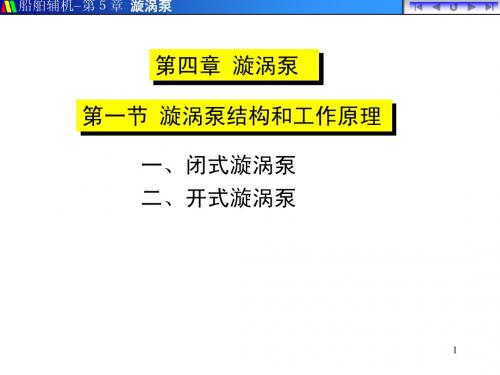
第一节 旋涡泵 一、构造和工作原理 二、性能和特点
1
船舶辅机第4章 漩涡泵 [Turbine Pump]
一、旋涡泵的构造和工作原理
种类: 开式:开式叶轮
闭式:闭式叶轮
1. 闭式漩涡泵:采用闭式叶轮和开式流道
基本结构:叶轮、泵体 (流道和吸排口)、泵盖
临界状态:h ↓, μ不再 ↑时的状态。
临界引射系数:临界状态的引射系数。 μcr 临界扬程比:临界状态扬程比。 r 可在临界状态长期工作。超过则效率急剧下降。
10
船舶辅机第4章 喷射泵 [Injection Pump]
三、喷射泵的性能和特点
喉嘴面积比 :m = d3 / d1 m 小,μ小,h大。 中扬程水射水泵, m = 3~7 。 喉嘴距:喷嘴出口至混合室进口的距离。 lc
表4-1 各类泵性能比较(自学)
12
2、开式漩涡泵
开式叶轮:
配开式流道
不能自吸
配闭式流道
能自吸
配向心开式流道 能自吸
配开式流道+辅助闭式流道
能自吸
开式流道:流道不经叶片间直接与吸排口相通。 闭式流道:流道需经过叶片间才能与吸排口相通。
阿尔法拉维尔SX旋转漩涡泵介绍说明书

pressures up to 15 bar.Benefits•Low pulsation and very gentle pumping, making the pump ideal for sensitive products.•Minimized shearing for protecting end-product quality.•Low maintenance, increased process uptime.•Maximized performance and minimized risk ofcontamination.Standard designAll media contacting steel components, like the rotor case, front cover, rotors and rotor nuts, are in W. 1.4404 (AISI 316L). The robust stainless steel gearbox provides maximum shaft rigidity and easy oil seal replacement. The gearbox design is universal which enables the flexibility of mounting pumps with the inlet and outlet ports in either a vertical or horizontal plane by changing the foot and its position.The standard Alfa Laval SX has four-lobe rotors rated to 150°C, facilitating use with CIP and SIP processes.Fully front-loading and fully interchangeable single, single flushed, and double mechanical shaft seals are available. All media contacting elastomers are controlled compression joints, the latest technology where static and dynamic elastomer seals are used to prevent leakage of pumped media to the atmosphere.The Alfa Laval SX can be supplied either as a bare shaft pump or mounted on a base plate complete with coupling, guard, gear motor and shroud for easy, plug-and-play installation. Working principleA gear train in the pump gearbox drives the rotors and provides accurate synchronization of the multi-lobe rotors. The movement of the counter-rotating rotors creates a partial vacuum that allows atmospheric pressure or other external pressures to force fluid into the pump chamber. As the rotors revolve, an expanding cavity forms, filling with fluid. As the blades disengage, each dwell forms a cavity. As the rotor blades engage, the cavity diminishes, and fluid is displaced into the outlet port.TECHNICAL DATAInside surface finish:Mech Ra ≤ 0.8Gearbox:Stianless steel Base plate:Stainless steel Coupling guard:Stainless steel Rotor:Four-lobe Product wetted elastomers:EPDM Other elastomers:FPMShaft seal:Single mechanical (R00)Rotary seal face:CarbonStationary seal face:Stainless steelMax flush pressure, single flush:0.5 bar Max flush pressure, double mechanical: 1 bar over product pressure Water consumption, flushed or double mechanical:0.5 l/min Flush connections:BSPT or NPTMedia contacting elastomersAll media contacting elastomers are controlled compression joints, the latest technology where static and dynamic elastomerseals are used to prevent pumped media leaking to atmosphere.1.Front cover compression joint2.Spline sealing cup seal3.Cup seal4.Squad ringFlows/Pressures/ConnectionsSX1/0070.07 1.54 1.8540 1.571001200SX2/0130.128 2.82 3.3840 1.5152151000SX2/0180.181 3.98 4.7850271001000SX3/0270.266 5.857.03502152151000SX3/0350.357.709.25652.571001000SX4/0630.6313.8616.6565 2.5101451000SX5/0820.8218.0421.6765 2.515215600SX5/115 1.1525.3030.3880310145600SX6/140 1.4030.8036.9980315215500SX6/190 1.9041.8050.20100410145500SX7/250 2.5055.0066.05100415215500SX7/380 3.8083.60100.40150610145500Note 1. These pressure ratings may vary for pumps with certain threaded connections.SX210SX313SX416SX519SX625SX728WeightSX1/0071617SX2/0133233SX2/0183334SX3/0275759SX3/0355961SX4/046107110SX4/063113116SX5/082155155SX5/115165165SX6/140278278SX6/190290290SX7/250336344SX7/380358366Shaft Seal Options•Single or single flush/quench (steam barrier for aseptic application) R00 type mechanical seals.•Double R00 type mechanical seal for flush.All sealing options are fully front loading and fully interchangeable without the need for additional housings or pump component changes. Specialised seal setting of the mechanical seal is not required as the seal is dimensionally set on assembly. This feature further enhances fast and efficient on-site seal interchangeability.Materials for Mechanical SealsCarbon/Stainless Steel, Silicon Carbide/Silicon Carbide or variations of these materials to suit fluid being pumped and/or application requirements. The seal seat and face material combinations are all EHEDG compliant.Standard Specification Options•Screwed male inlet and outlet ports to DIN11851, DIN11864, SMS, ISS/IDF, RJT or Tri-clamp.•Heating/Cooling Jacket for Rotorcase Cover.•ATEX compliance.•Complete pump unit comprising: Pump + Baseplate (mild or stainless steel) + coupling with guard + Geared electric motor suitable for (or supplied with) frequency speed control or manual variable speed drive (advise motor enclosure and electrical supply).Pump SizingIn order to correctly size a rotary lobe pump some essential information is required. Provision of this information listed below enables our Technical Support personnel to obtain the optimum pump selection.Product/Fluid Data •Fluid to be pumped •Viscosity •SG/Density•Pumping temperature, minimum, normal and maximum•Cleaning in Place temperature(s), minimum, normal and maximum Performance Data•Flow rate, minimum, normal and maximum•Discharge head/pressure (closest to pump outlet)•Suction conditionBareshaft Pump DimensionsFigure 1. Vertically ported All dimensions in mmSX1/0074095113208151640305296601008022114104801017423.5SX2/0134010514725216225032632758.5111100121241241001221332.5SX2/0185010514725216225032634365.5111100121241241001221332.5SX3/0275012517530022286040843472.5142155151851551251424637.5SX3/0356512517530022286040845078142155151851551251424637.5SX4/04650150213363253880631051775174200172341841501430149.5SX4/06365150213363253880631053681.5174200172341841501430149.5SX5/082651752574322745110701460261264200202402201801435160SX5/115801752574322745110701463080.5264200202402201801435160SX6/140801902954852748110701469178267260203002502101440070SX6/1901001902954852748110701471990267260203002502101440070SX7/2501002053655702660110901876794288280253302902401847581.5SX7/38015020536557026601109018821121288280253302902401847581.5TOP SHAFTDRIVEFigure 2. Horizontally portedAll dimensions in mmSX1/007409590.5189101640671143052963612480101001008010SX2/0134010511523316225082.5147.532632738.51311001913212410012SX2/0185010511523316225082.5147.532634345.51311001913212410012SX3/027********.527218286010017540843469.51751253018115412514SX3/0356*******.5272182860100175408450751751253018115412514SX4/04650150163325203880113.5212.56310517752241503520218415014SX4/06365150163325203880113.5212.5631053681.52241503520218415014SX5/0826517519538222451101352557014602662791803524021018014SX5/115801751953822245110135255701463085.52791803524021018014SX6/1408019022543622481101552957014691782672602030022019014SX6/19010019022543622481101552957014719902672602030022019014SX7/250100205276.552427601101953589018767992732902534029024018SX7/380150205276.5524276011019535890188211262732902534029024018 This document and its contents are subject to copyrights and other intellectual property rights owned by Alfa Laval Corporate AB. No part of this document may be copied, re-produced ortransmitted in any form or by any means, or for any purpose, without Alfa Laval Corporate AB’s prior express written permission. Information and services provided in this document are made as a benefit and service to the user, and no representations or warranties are made about the accuracy or suitability of this information and these services for any purpose. All rights arereserved.200006104-2-EN-GB© Alfa Laval Corporate AB How to contact Alfa LavalUp-to-date Alfa Laval contact details for all countries are always availableon our website at 。
旋流泵设计说明书
JIANGSU UNIVERSITY本科毕业设计毕业设计说明书学院名称:能源与动力工程学院专业班级:J动力流体0901学生姓名:杨锡平学号:3091104028指导老师:杨敏官高波李忠2013年6月毕业设计题目旋流泵设计(ns=63)目录第一章摘要----—————————————4 第二章叶轮水利设计———————————6 第一节概述—————————————6第二节参数计算———————————7 第三章压出室水利设计—————————— 26 第四章标准件的选用——————————— 31 第五章强度计算————————————— 32 附毕业小结——————————————39 参考文献——————————————40第一章摘要内容摘要泵可能是世界上除了发动机外运用最广泛的机械了,凡是有水流动的地方就会有泵在工作。
它被广泛应用于工业,农业,军事业等,已经成为人们生活所不可缺少的一部分。
矚慫润厲钐瘗睞枥庑赖。
旋流泵是离心泵的一种,因其内部流体存在旋转的漩涡运动而得名。
旋流泵多用于抽送复杂介质或含杂质流体,如含垃圾,短纤维物质或含便类的两相流体。
旋流泵亦称无堵塞泵,自由流泵或WEMCO泵。
聞創沟燴鐺險爱氇谴净。
本次设计的内容是旋流泵。
旋流泵设计的结构特点是叶片为开式或半开式叶片为直叶片并呈放射状布置。
叶轮与前泵壳之间有较宽的轴向空间,或者说叶轮后缩至泵壳后腔,这便为固体介质通过泵体提供了良好的条件。
残骛楼諍锩瀨濟溆塹籟。
AbstractPump may be the most universal machine in the world except for electric motor. where there is flowing water,there is a pump.It’s applied in many fields,such as industragriculture, military etc.Pump is essencial in people’s daily life.酽锕极額閉镇桧猪訣锥。
0104漩涡泵—喷射泵
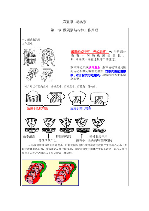
第五章 漩涡泵 叶片形状有径向直叶、前倾直叶、后倾直叶、后转角、前转角。
环形流道中液体的圆周速度小于叶轮的圆周速度,使得流道中液体产生的离心力小于叶轮中液体的离心力,液体就会从叶片间甩出,迫使流道中的液体产生向心流动,再次从叶片根部进入叶片之间形成了纵向旋涡(螺旋线)适用于低比转数 适用于高比转数效率最高特性曲线平坦 特性曲线陡 撞击小、压头高特性曲线陡特性曲线平坦高(3)开式旋涡泵特点:1)液流进入叶轮处叶片的圆周速度较小,汽蚀性能比闭式旋涡泵好。
2)采用闭式流道的开式旋涡泵只要将吸、排口朝上安装,并在初次起动前向泵内灌满液体,就具有自吸和抽送气液混合物的能力。
3)采用闭式流道虽然能够排送气体和提高泵的自吸能力,一﹑单选题:1. 开式旋涡泵是指。
A.泵与电机不在同一壳体内B.流道两端直通吸口或排口C.叶轮无中间隔板或端盖板D.流道有一端有直通吸口或排口2. 闭式旋涡泵是指。
A.流道不直通吸排口B.叶轮无中间隔板或端盖板C.电机与泵封闭在同一壳体内D.与B相反3. 旋涡泵情况可能存在。
A.闭式叶轮配闭式流道B.开式叶轮配闭式流道C.开式叶轮配开式流道D.B或C4. 旋涡泵叶片采用。
A.前弯B.后弯C.径向D.三种都有5. 旋涡泵属叶轮式泵。
A.低比转速B.中比转速C.高经转速D.不用比转速概念6. 刻涡漏泄一般主要发生于。
A.叶轮整个圆周处的径向间隙B.叶轮端面的轴向间隙C.叶轮在隔舌圆周处的径向间隙D.轴封处参考答案旋涡泵与离心泵的比较:在叶轮直径、转速和级数相同的条件下,的2~4倍。
闭式旋涡泵单级扬程一般为15~150m,二级可达150m10~40,ns大于40时其效率远低于离心泵。
一﹑单选题:1. 采用开式流道的开式旋涡泵加辅助闭式流道是为了。
A.提高效率B.具备自吸能力C.降低必需汽蚀余量D.A+B+C2. 三级以上的多级旋涡泵。
A.采用开式B.采用闭式C.A或BD.不可能有3. 旋涡泵初次使用时向泵内灌水主要是为了。
三环牌 XGB系列旋涡气泵 说明书

致用户书为方便客户,减少购买产品交通运输不便的困难,本公司在市内五爱广场棉花巷六号设立产品销售门市部。
主要业务:1、销售本公司产品及各类正宗配件。
2、精心修理各类气泵。
欢迎客户前往联系。
我公司将提供优良服务,并可协助客户联系运输、食宿等事项。
交通路线:(参阅封底示意图)长途汽车西站及轮船码头在运河饭店乘11路汽车到五爱广场站下;火车站乘2路汽车五爱广场站下或乘10路、11路、15路、16路汽车在五爱广场(西门)下车。
无锡中策机电设备有限公司二OO三年六月- 2 -XGB系列旋涡气泵使 用 说 明 书一、工作原理:旋涡气泵的叶轮上有数十片叶片组成。
它类似庞大的气轮机的叶轮。
当旋涡气泵的叶轮旋转时,叶轮叶片中间的空气受到了离心力的作用,朝着叶轮的边缘运动,在那里空气进入泵体的环形空腔,然后又返回叶轮。
重新从叶片的起点以同样的方式又进行循环。
由于空气被均匀地加速,叶轮旋转所产生的循环气流使空气以螺旋线的形式穿出,所以空气以极高的能量离开气泵以供使用。
二、结构特点:旋涡气泵采用专用电机,结构紧凑,体积小,重量轻,不需要变速装置,内部除电机转子两端轴承外其它部位没有直接接触摩擦、噪音低,气源无水无油。
三、用途和范围:XGB系列旋涡气泵是一种吹气或吸气两用的通用气源。
它主要用于:切纸机、燃烧降氧机、卷烟滤嘴成型机、电镀槽液搅拌、雾化干燥机、水处理曝气、水产养殖、丝网印刷机、照相制版机、注塑机自动上料烘干机、液体灌装机、粉末灌装机、电焊设备、电影机械、纸张运送、干洗衣服、清洁用途、空气除尘、干瓶、气体传送、送料、收集等方面。
- 1 -旋涡式气泵性能一览表(Table Of Regenerative Pump Specifications)- 2 -- 4 -口气出进- 5 -- 6 -进出气口外形尺寸mm- 7 -XGB系列旋涡气泵- 8 -四、使用和保养:1.气泵应放置在较平稳的地方,周围环境应清洁、干燥、通风。
变流量漩涡式水力泵:电动驱动发展的水力解决方案说明书

Variable Flow Vane PumpThe Hydraulic Solution for the Evolution of Electric DrivesVariable Flow Vane PumpThe Hydraulic Solution for the Evolution of Electric DrivesDr.-Ing. Gerd Scheffel is1991 to 2014.Dr.-Ing. Roland Bublitz is industrial applications engineer-ing manager for Parker in Kaarst, Germany. He holds a diploma and a PhD in mechanical engineer-Th e variable-speed hydraulicpump, with its potential for energy savings, power density and tempo-rary noise reduction, is currently the dominant pressure supply system in the media. It provides a clear example of how hydraulics can successfully participate in the evolution of electric drives. Promotions for the variable-speed pump like to suggest that stand-alone individual drives are the future for hydraulics. Electrohy-draulic actuators have their uses, of course, but it is important to re-member that electric motors, and their converters, are what make electromechanical drives so costly. Each drive needs a fi xed mo-tor, which makes the drive large and expensive. If this principle is applied to hydraulics, it restricts the choice of appropriate pumps to those variants that are suitable for four-quadrant operation. Th is limits options and increases costs as well.Th e multiple use of the electric motor in the central supply, to-gether with the large range of suit-able two-quadrant pumps (pumps in which the P- and T-attachments on the pump remain in place un-changed, regardless of the direc-tion of fl ow; that is, the high pres-sure is always on P , and T is always connected to the tank), provide good economic arguments in favorof hydraulics as opposed to elec-tromechanical systems. Because the central supply is connected to the drive with pipes and hoses – this is why hydraulic drives are often so compact – the power can be fed around any corner. When marrying hydraulic pumps with electric motors, one has to take into account the behavior of each system, as determined by its construction type, with respect to its hydraulic, electrical and me-chanical characteristics.A variable hydraulic fl ow can be created with an adjustable-fl ow pump, a fi xed-displacement pump on a variable-speed electric mo-tor, or a combination of both: a variable-fl ow pump on a variable-speed electric motor (Figure 1). Studies so far suggest that the last of these is the most energy-effi cient combination, but also the most expensive. With smaller fl ow rates in particular, this expense cannot be justifi ed, and it is prefer-able to adopt more economical solutions involving fi xed-displace-ment pumps. Th e lon g-established option of a variable-fl ow pump on a constant-speed asynchronous motor is almost unanimously considered to be the benchmark solution.Figure 1: Options for varying fl ow rateCharacteristics ofelectric machinesAmong electric motors, the asyn-chronous motor was essentially designed to permit an automatic start without electronics on a three-phase supply. As a resultof the motor’s construction, it couples relatively loosely with the rotating fi eld (slow speed-change), and rotates at a speed determined by the number of poles in the sta-tor and the mains frequency; e.g., at 3,000 rpm with a 50 Hz 2-pole supply, at 1,500 rpm with a 4-pole supply, and at 1,000 rpm witha 6-pole supply. If a frequency converter is installed, the rota-tion speed of the asynchronousmotor can be adjusted from zeroto almost double the rated speedattainable on the grid withouta converter. Above the ratedspeed, however, in the so-calledfi eld-weakening range, motortorque decreases quadratic withthe rotation speed. Whether thelower rotation speed can be useddepends on the type of enginecooling. In self-cooled engines,cooling capacity decreases withrotation speed (the fan turns at thespeed of the motor). To achievea very low rotation speed over alonger period of time, therefore,external cooling (a self-propelledfan) is necessary.For cost reasons,asynchronousmotors gener-ally come withoutsensors; that is,they operate with-out speed feed-back. If the motoris to be operatedat rotation speedsunder 50 rpm,however, the useof speed feedbackis recommended.Th ere are alsoasynchronousmotors that aredesigned diff er-ently from IEC or‘standard’ motorsin order to achievebetter dynamicswith a smallerrotor diameter(the ‘main spindledrive’ design).Th ese motorshave a rectangularfl ange and arelonger at the samepower rating.Many of these mo-tors are fi tted withencoder feedback,and are thereforealso known as asynchronous servomotors.Th e synchronous motor cannotrun by itself on a three-phasesupply, and needs a frequencyconverter to do so. Th e rotor is fi t-ted with permanent magnets, andis therefore coupled very fi rmlywith the rotating fi eld of the stator.Th e speed range is often greaterthan with standard asynchronousmotors, and the dynamics areconsiderably better. Because noinduction is needed in the rotor,power dissipation is lower, thusreducing heating of the motor.Electric motors can achieve con-siderably higher rotation speedsFigure 2: Combinations of electric motors and hydraulic pumpsthan most hydraulic pumps. When choosing a motor, therefore, it is important to consider the usability of the rotation speed. Th e rota-tion speed of hydraulic pumps is restricted by noise characteristics, centrifugal forces and suction capacity. Th ese restrictions are particularly clear with electric drives on a 60 Hz grid and with diesel drives. Small pumps reach their limits at around 3,000 rpm, and large pumps at around 2,000 rpm, if they are self-primed. Pumps with adjustable rotation speedAn adjustable pump can varythe fl ow rate very quickly; e.g., by adjusting the pivoting angle at afi xed rotation speed. With a fi xed-displacement pump on a variable-speed electric motor, the rotationspeed of the electric motor unit as a whole must be adjusted with a hydraulic pump coupled with the motor. Th e torque, which will change very quickly as a result of this adjustment, must be transmit-ted through all hydraulic compo-nents of the pump that lie in the power fl ux (Figure 2).Pumps with an adjustable rota-tion speed must satisfy require-ments and operating conditions that do not arise under operat-ing conditions with a fi xed drive speed. An axial piston pump of the swashplate type is ill-equipped for a rapid change in speed: the torque is transferred in the motor via the oscillating pistons through short contact lines to the piston barrel. Th is restricts the rotation adjustment speed, and hence the dynamics. Th us, the high dynam-ics of a synchronous motor cannot be used, because the mechani-cal components of the hydraulic pump cannot transfer them. For this reason, pivot-adjustable piston pumps, both with fi xed and with variable rotation, mostly runon a cheaper asynchronous motor,and the dynamics are created byadjusting the pump.Th e alternative to the swashplatepiston motor is the fi xed-displace-ment bent-axis piston motor. Th eshaft torque in some designs istransferred to the piston barrelthrough mechanical coupling;e.g., through two gears in mesh.Th e pistons move without beingsubject to shear forces, and thisdesign is therefore very suitable forrapid speed change. Th is machin eshows particular mechanicalrobustness when the motor is inoperation, as it operates with rota-tion speeds of up to 14,000 rpm.Th e internal gear pump, whichcurrently dominates the fi eld invariable-speed pumps, has twointerlocking gears in mesh. Th isis useful for transferring a rapidspeed change, such as the kindthat occurs in pressure control,between the rotating/moving partsFigure 3: Integrated vane pump on a synchronous motorin a mechanically sound way.Just like the internal gear pump,the external gear pump is verywell-suited to rapid speed changeson a synchronous motor. Becauseof its larger pressurized surfaces,however, it is less favorable in theresulting bearing forces it cre-ates, which reduce the maximumpressure and create a higher levelof friction, particularly at low rota-tion speeds. Th ere are numerouspumps on the market that havehelical gears for noise-relatedreasons.Advantages of vane pumpsAnother pump that is very suit-able for internally transferring thevarying levels of torque is the vanepump. In this pump, large-surfacevanes occupy slots in the rotor. Th etorque is transferred not throughlinear contact, but through full-area contact of the vane with therotor, which makes this designparticularly robust. Th e hydrauli-cally balanced vanes, which arepressed onto the external curved path by centrifugal force, are also spring-loaded, which ensures contact with the external curved path even at lowest rotation speeds. Two opposing pump chambers balance the hydraulic load fully, so bearings are not needed to carry the load, but only to guide the shaft. As a result, the pump rotor can also be operated directly from the extended shaft end of an electric motor. Th is means that the shaft bearing, the bell housing and the coupling are not required, which results in afi rmer coupling of the pump with the electric motor. Th is not only shortens the overall length of the unit as a whole, but also reduces its inertia and prevents torsional vibrations as a result of the elastic-ity of the coupling, which permits a high level of dynamics. Th e van e pump is suitable for various fl uids, as it has no roller- or ball-bearings in the liquid. Because of the bear-ing-free installation of the pumpcartridge, in cases of repair it caneasily be replaced with a built-inpump by loosening the four screwson the cover (Figure 3).Th e use of variable-speed pumpsenables control of fl ow rate andpressure directly through thepump rotation speed. Pressurecontrol, in particular, imposesdiff erent requirements on thepumps. Th us, depending on theapplication, it may be necessary toset the working pressure betweenlow and no initial fl ow volume fora period of time. In this state, thepumps heat up because of internalleakage. Th e smaller the internalleakage of the pump, the longerthe dwell time of the pump beforea critical temperature is reached inthe pump. Once this temperatureis reached, the lubrication proper-ties of the hydraulic medium areno longer suffi cient to separate themoving parts of the pump, and thisresults in a mechanical failure. Th etwo most important requirementsfor variable-speed pumps are theability to transfer high torques,and low internal leakage.Internal leakage includes not justleakage in the displacement space,but also all other oil fl ows insidethe pump, because such fl owsalso cause losses and, in the caseof pressure control, heating of thepump.Adjustable swashplate pistonpumps must feed the hydrostaticbearings of the piston shoe andsupply the control unit for adjust-ing the swashplate with pilot oil.Th ese additional oil fl ows lead toa reduction in the effi ciency ofthe machine, which operates withsuch low losses in the displace-ment space.Figure 4: Overall effi ciency of the T7B vane pump and internal gear pump of 32 ccm and 50 ccmTh e fi xed-displacement bent-axis machine has the advantage over the swashplate machine, in variable-speed operation, thatthe pistons are supported on the bearing by spherical balls. Th is re-duces the supply to the hydrostatic bearings, and because it operates constantly, it has no control unit that needs to be supplied. Th is machine has very high effi ciency. On the other hand, its construc-tion costs are high.Internal leakage mainly depends on the length and height of the sealing gaps of the displace-ment spaces. In this sense, piston machines have a clear advantage, because a round piston in a round hole can be manufactured with very narrow tolerances. Pistons with a larger diameter and a longer piston stroke create larger displacement volumes. Th ere is a proportional relation between leakage and displacement. Toothed fl anks or vanes vary in their suitability for sealing the cross-sectional displacement space, and the side fl anks of the gears or vane rotors are also dif-fi cult to seal without creating large frictional forces. Th ere is more leakage at these points than with piston machines. Gear pumps, both with external and internal gear teeth, are manufacturedwith diff erent gear sizes, and the displacement volumes within a construction size are defi ned by diff erent gear widths. Th ere is a proportional relation between leakage and displacement. In pressure-compensated designs for internal gear pumps, the sealing gap at the tooth tip reduces as pressure increases. Th is in creases volumetric effi ciency, but also increases mechanical losses. Vane pumps are manufactured with diff erent rotor diameters, and within a construction size thedisplacement volumes are defi nedby the profi le of the stroke ring. Inthis construction type, the lengthsof sealing gaps remain almostconstant. Internal leakage onlyvaries slightly as a result of the dif-ferences in vane stroke size. Th us,the pump with the largest dis-placement volumes, which has thelargest vane stroke, has almost thesame internal leakage as the pumpwith the smallest. Th ere is a pro-portional relation between leakageand displacement volumes acrossthe range, but this declines withina given construction size, thusincreasing the effi ciency. Th e mosteff ective combinations are almostas good as the most eff ective inter-nal gear pumps (Figure 4).Th e lengths of sealing gaps areroughly the same in internalgear and vane pumps, and thusboth types of pumps exhibit verysimilar leakage rates up to me-dium pressures. In terms of energyeffi ciency of the system, effi ciencyis crucial at high rotation speedsand pressures, because this iswhere the most energy is used. Atsmall rotation speeds, effi ciencyis important for the pump itself,because in pressure-holdingoperation the pump is barely ableto dissipate heat. In the absenceof fl ow, only internal leaking ispumped. Th e T7E15 pump is ofthe same construction size as theT7E10, but has the largest vanestroke and hence is better in termsof effi ciency. At identical displace-ment volumes, the pump has toturn faster the greater the leakageis. Internal gear and vane pumpsare equivalent; at higher pres-sures, the vane pump has to turnsomewhat faster (Table 1).Because this heat cannot bedissipated without a drain port(which is normally dispreferredwith fi xed-displacement pumpsin order to simplify installation),the maximum pressure-holdingtime up to the heating limit isa function of leakage. A higherlevel of leakage means a shorterpressure-holding time in the ab-Table 1: Comparison of rotation speeds in pressure-holding operation depending on volume of effi ciency of a vane pump and an internal gear pump of 31.8 ccmsence of fl ow. However, a higher level of leakage also entails a higher rotation speed and thus a lower pressure pulsation. If the pressure-holding time that can be achieved is not suffi cient for the application, a small amount of fl ow to eliminate the dissipa-tion loss of the pump will extend this time considerably. For the most part, leakage will provide suffi cient fl ow for the connected device to achieve suffi ciently long pressure-holding times for the application (Table 2). Compact and robustTh e trend towards variable fl ow rates is forcing manufacturersof fi xed-displacement pumpsto adapt their products for variable-speed operation. In the future, a wider range of designsis to be expected on the market.A variable-fl ow vane pump is already available as an additional option alongside more estab-lished products. Th is pump is quieter than a piston machine and has a considerably simpler design. The vane pump is com-Table 2: Pressure-holding time (T ≤ 90 °C, HLP32) of a vane pump of 50 ccm depending on volume of effi ciencyparable in terms of hydrauliceffi ciency and noise characteris-tics, and, at medium pressure atno fl ow condition, it has almostthe same pressure-holding timesas an internal gear pump. Withrespect to the pressure-holdingtimes of fi xed-displacementpumps in general, it should benoted that, in practice, the needBibliography[1] H. Murrenhoff, Grundlagen der Fluidtechnik, Band 1: Hydraulik, 6. Aufl age, 2011[2] R. Bublitz, K. Roosen, Energetic optimization of variable speed pump systems, 9. Internationales Fluidtechnisches Kolloquium, Aachen, 2014for pilot oil and the leakages of thecomponents of the total hydraulicsystem, impose no restrictions.Th e vane pump is the only pumpthat can run on the extended shaftof the electric motor, which makesthis integrated solution uniquelycompact and robust.[3] T. Neubert, J. Wolff, S.Helduser, H. Spath, Untersuchungelektrischer Antriebssysteme amBeispiel von Hydraulikpumpen;Antriebstechnik 43 Nr. 1, 2004[4] I. Rühlicke, Elektrohy-draulische Antriebssysteme mitdrehzahlveränderbarer Pumpe,Dissertation, Technische Univer-sität Dresden, 1997© 2016 Parker Hannifi n Corporation Parker Hannifi n ManufacturingGermany GmbH & Co. KGHydraulics Group Europephone + 49 (0)2131 513-0。
第五章漩涡泵
船舶辅机−第5章 漩涡泵
3.径向力和轴向力 . 径向力: 径向力:旋涡泵中从吸口至排口液体压力沿圆周 近似呈线性增加,任何工况都会产生不平衡径向 力,其作用方向大致垂直于通过隔舌中间位置的 轴截面,指向低压侧。径向力由轴承承受。 轴向力: 轴向力:流道截面左右对称的旋涡泵理论上不产 生轴向力,但若叶轮两端面间隙不等,会引起压 力不等,产生轴向力。通常在叶轮上开平衡孔消 除。单侧流道的旋涡泵因叶轮两端面液压力不同, 引起指向流道方向的轴向力,小型泵用止推轴承 承受。 泵
纵向旋涡越强, 纵向旋涡越强,液体质点进入叶轮的次数就越 泵产生的扬程就越高。 多,泵产生的扬程就越高。纵向旋涡的强弱取 决于:a.叶轮内液体和流道内液体的离心力之 决于 叶轮内液体和流道内液体的离心力之 纵向旋涡的流动阻力, 差;b. 纵向旋涡的流动阻力,与叶片和流道的 形状及叶片的数目有关。 形状及叶片的数目有关。 闭式漩涡泵的特点: (1)效率较高 效率较高(35~45%); 效率较高 ; (2)汽蚀性差 液体径向进入 ,汽蚀余量较大; 汽蚀性差(液体径向进入 汽蚀性差 液体径向进入),汽蚀余量较大; 无自吸能力, (3)无自吸能力,不能抽送气液混合物。若要自 无自吸能力 不能抽送气液混合物。 排出端必须设气液分离室; 吸,排出端必须设气液分离室; (4)多为单级或二级。 多为单级或二级。 多为单级或二级 3
结论:旋涡泵适用于小流量、高扬程、 结论:旋涡泵适用于小流量、高扬程、功率较小 适用于小流量 和需要自吸的场合,适宜输送粘度较低、 和需要自吸的场合,适宜输送粘度较低、不含固 体杂质的液体或气液混输。 体杂质的液体或气液混输。如辅锅炉或压力水柜 的给水泵。 的给水泵。
12
船舶辅机−第5章 漩涡泵
离心旋涡泵
Agilent TwisTorr FS 涡流式涡旋膨胀式泵系列说明书

Agilent TwisTorr FSTurbo Pump FamilyThe new generation Turbo Pumpswith TwisTorr drag technology and Agilent Floating SuspensionAgilent Quality and ReliabilityYour Benefit–Reduced cost of ownership and system down-timeEasy System IntegrationYour Benefit–Compact design –P lug and play –E asy pump driving and monitoring –O peration in any position–O il-free solutionTwisTorr FS Family Features–Ceramic ball bearings withpermanent lubrication–PCB, onboard, rack control units with Serial and Profibus communication–Retrofitable to any pumpIndustrial and SemiconductorsThe TwisTorr FS turbo pumps offer dry, clean vacuum for demanding in d ustrial and semiconductor applica t ions.Agilent TwisTorr FS Pump ApplicationsThe new TwisTorr FS technology represents a unique blend of performance and features that is perfectly suited for a wide range of applicationsAcademia, Government and ResearchUnmatched vacuum performance in its class, with TwisTorr stages op t imized for H2 compression, make it the ideal solution for demanding ac a demic and research applications.Surface AnalysisThanks to low vibration, low noise and high stability, the TwisTorr FS turbo pumps meet the specific needs of electron microscopes.Analytical InstrumentationHigh throughput and optimized per f ormance for light gases in routine applications are suited perfectly for use in analytical instruments.2Now FeaturingYour solution for high performance, quality, and reliability* The new TwisTorr 704 FS – CutawayQuiet and Low-VibrationYour Benefit–Excellent vibration level (damping effect) –Quiet pump during operationTwisTorr FS Family Features– A gilent Floating SuspensionSuperior PerformanceYour Benefit–Low ultimate pressure –Fast pumpdown–Smaller/less expensive backing pump –Suitable for high gas load applications–Lower power consumptionTwisTorr FS Family FeaturesTwisTorr Drag Stages allow for: –Superior compression ratio–High foreline pressure tolerance –Best-in-class pumping speedTwisTorr FS Family Features– A gilent Floating Suspension – B earings and rotor stable/constant positioning over timeNew 3D Software for Pump Control✓ Optimized Performance, Maximum Flexibility and Extended Reliability ✓ Dynamic speed and power tuning according to inlet pressure, gas load, and temperature✓ Always the best performance in every working point Learn more, see pages 8-93704 FS, 804 FSAgilent Warranty:and ReliabilityVibration test - TwisTorr 404 FS, 704 FS, 804 FS*The compatibility with vibrations generated by external sources was proven through a set of tests on a batch of pumps, both in operative and inoperative conditions.Each pump was exposed to energy levels from 0.5 to 2 g during 105 minutes’ vibration cycles in vertical, horizontal, upside-down orientation at full rotational speed and not operative.The test confirmed pump robustness and fullcompatibility to vibrations as No rotor mechanical contacts or change to pumps’ operation werehighlighted and the pump unbalance remained well below acceptance threshold.Lifetest - TwisTorr 404 FS, 704 FS, 804 FS*Pump reliability proven through an accelerated life test on a significant number of pumps, exposed for extended time to accelerating factors.The test provided confidence in pump’s hassle-freeoperation for an average period longer than five years.Shock test - TwisTorr 404 FS, 704 FS, 804 FS*Pump resistance to shocks proven by a set of tests on a batch of pumps both in operative and inoperative conditions.Every pump exposed to a 30 to 120 g acceleration (equivalent to a drop from 82 cm / 32” - not operative pump, and 15 cm / 6” - operative pump).Pumps shock-tested six times in vertical, horizontal, upside-down orientation.No issue occurred to the tested pumps after the full batch of 24 drops (No rotor mechanical contacts, No change to pumps operation).The pump unbalance verified after every drop highlighted minor variations,remaining well below acceptance threshold : the shock test confirmed the pumprobustness and reliability.Agilent TwisTorr FS Turbo PumpsTwisTorr FS: Design Process, Quality, and Reliability Test ElementsThe «Product Life Cycle» method drives and tracks the design process through the six steps of proposal, investigation, lab prototype, production prototype, pilot run, and ramp to volume. Reiterated controls and tracking ensure full confidence in performance, quality, and the regulatory data published for users.4Quiet and Low-VibrationStability OverTimeThermal test - TwisTorr 404 FS, 704 FS, 804 FS*Pumps were exposed for 86 h to temperatures ranging from -40 °C to +70 °C (not operative) and from 0° C to 40 °C (operative).The pump unbalance and correct operation was verified 11 times on everypump finding only minor variations, well below acceptance threshold. The thermal test confirmed the pump’s robustness and full compatibility to every operative and not operative temperature condition of applications or during storage and transport.Fourier analysisTwisTorr 404 FS, 704 FS, 804 FS*The pump vibration spectrum is verified on every pump during the manufacturing process and before the pump shipment as a final test of pump’s correct operation.Average maximum vibration level at full speed: 0.4 m/s 2.Noise testTwisTorr 404 FS, 704 FS, 804 FS*Pump noise was verified through a set of tests on a batch of pumps in 12 different operative statuses and orientationsincluding: vertical, horizontal, and upside-down positions; with and without gasload; high temperature and low temperature; full speed and low speed.The average pump noise resulting from the 168 measurements was 43 dB(A) +/-3σ in normal operation.Packaging test - TwisTorr 404 FS, 704 FS, 804 FS*The packaging functionality verified with test session on packed pumps, subjected to a test of 18 drops from 96 cm (37.8 inch) height.The test confirmed that packaging can limit the acceleration provided to the pump during a typical transportation to the 30 g.From the shock test, we know that 30 g is a level ofacceleration fully compatible with TwisTorr pump design.*NOTE: Test data provided arereferred to TwisTorr 404 FS, 704 FS, 804 FS – similar data are available on request even for 84 FS and 304 FS.FFT Analysis - TwisTorr 404 FS, 704 FS, 804 FSNoise distribution cart - TwisTorr 404, 704, 804 FS5Space Saving Design–Our rotor is based on the proven Agilent monolithic rotor design, which positions the TwisTorr stator between two smooth spinning disks and therefore exploits the pumping action by both disk surfaces in series. –The double-sided spiral groove design on theTwisTorr stators combines centripetal and centrifugal pumping action in series, greatly reducing the size of the drag section.Agilent TwisTorr Technology*–Pumping effect is created by a spinning rotor disk, which transfers momentum to gas molecules. –Gas molecules are forced to follow spiral groove design on the stator. The specific design of the channel ensures constant local pumping speed and avoids reverse pressure gradients, minimizing power consumption.(*) US Patents applications 12/343961 and 12/343980, 24 Dec. 2008.Compression ratio–Compression ratio for N 2 of a single TwisTorr stage can increase up to a factor of 100 with respect to a MacroTorr stage of the same space and rotor speed, without reducing foreline tolerance and pumping speed.Leading Edge Performance–The TwisTorr pumps offer the highest pumping speed in their category for all gases. –The state of the art TwisTorr technology also achieves the highest compression ratios for light gases in a commercially available turbomolecular pump. –While offering the highest performance, average power consumption by the new drag section design is reduced by a factor of four, compared to previous designs.Spiral groove design on the upper section of the TwisTorr stator causes a centripetal pumping action).Gas flow in centripetal and centrifugal direction throughTwisTorr channelsThe pumping effect is repeated for each of the pump’s TwisTorr stagesSpiral groove design on the lower section of the TwisTorr stator causes a centrifugal pumping action.What is TwisTorr?The new molecular-drag technology, applied to the entire family from 84 FS to 804 FSCentripetal pumping action Lower surface area of rotating disk transfers momentum to gas molecules.Centrifugal pumping action Upper surface area of rotating disk transfers momentum to gas molecules.6What is Agilent Floating Suspension?Innovative solutions for low vibration and stability over timePerfect bearing alignmentVibration damping–AFS geometrical precision guarantees perfect bearing alignment –Designed radial and axial stiffness,optimized rotor dynamic behaviour, and acoustic noise –Lower AFS acts as an axial springproviding bearing preload and axial rotor positioning –Thermal stabilityRadial press fitting to maintain the best working condition for bearings over timeHigh performance elastomer for vibration dampingTo ensure–Low vibration and acoustical noise –Optimal working conditions for the bearings, extended operating life –Exceptional stability for the very demanding SEM applicationLower AFSUpper AFSThermal stabilityOptimized rotor dynamic BehaviourTwisTorrrotor, floating suspension, and electrical motor7Maximum flexibility, speed, and simplicity, thanks to a unique smart vacuum system:Dynamic speed and power tuning according to inlet pressure, gas load, and temperature.Always the best performance in every working point.Steering towards flexibility, speed of execution, and simplicity, TwisTorr 404 FS, 704 FS, and 804 FS are now introducing a new Agilent innovative footstep - 3D pump control software.The innovative pump driving function provides maximum flexibility, speed, and simplicity: Always the best possible throughput performance according to the pump operative conditions.A unique vacuum system is able to quickly and automatically ensure the entire spectrum of customers’ application needs, from UHV to high gas-load, on a single turbo pump.An automatic routine manages the pump’s rotational frequency and power according to the required inlet pressure and gas-load, at the specific application’s temperature point.The new TwisTorr medium TMP Controllers.Rack or onboard, available for 404 FS, 704 FS, 804 FS pumps with 3D firmware for performance optimizationAgilent TwisTorr FS Turbo Pumps8«3D» software drives the pumpHigh Gas Flow High VacuumPump parameters dynamic setting/tuning––Power –TemperatureApplication requirements auto detection High Throughput High CompressionTwisTorr Technology Output/Performance 9Quality RepairWhen uncompromised quality at the right price is of essence You need a trusted partner to deliver it. Specialized Repair Centers around the globe bring Agilent quality standards closer to you.When your TwisTorr turbo pump needs attention, we have the right know how and the experience to deal with it. Your trusted solution:–Certified process andworkmanship–Genuine Agilent partsYour work is important to us. Our technology refresh programs and tailored service plans are designed to protect and secure your investment. Customized service contracts and a comprehensive upgrade program are designed around your business needs and make us the natural choice as your vacuum service partner. Your advantage:–Stay up to date with the technology–Close to your business –Personalized coverageDedicated Solutions 10Technical SpecificationsPumping SpeedCompression RatioTechnical SpecificationsPumping Speed12Technical SpecificationsArMax GasThroughput (*)N 2He Ar(*) Backing pump 11.6 m Compression ratio and foreline tolerance (**) N 2He H 2Ar(**) Foreline Tolerance defined as the pressure at which the turbopump still produce a compression of 100 and estimated in water cooling modeBase pressure with recomm.Pumping SpeedCompression RatioTechnical SpecificationsPumping SpeedP u m p i n g S p e e d (l /s )Compression Ratio C o m p r e s s i o n r a t i oRecommended forepumpAgilent DS102 Rotary Vane Pump Agilent IDP-7 Dry Scroll PumpAgilent TwisTorr FS Turbo Pumps14Pumping SpeedCompression Ratio1,E-08 1,E-07 1,E-06 1,E-05 1,E-04 1,E-03 1,E-02Inlet Pressure [mbar]1,E-2 1,E-1 1,E+0/chem/TwisTorrFSfamily15Agilent TwisTorr FS Turbo Pump FamilyThe new generation Turbo Pumps with TwisTorr drag technology and Agilent Floating SuspensionAgilent TechnologiesUnited StatesAgilent Technologies 121 Hartwell Avenue,Lexington MA 02421, USA Tel: +1 781 861 7200Fax: +1 781 860 5437Toll free: +1 800 882 7426*******************************ChinaBeijing OfficeAgilent Technologies (China) Co. Ltd No.3, Wang Jing Bei Lu, Chao Yang District,Beijing, 100102, China Tel: +86 (0)10 6439 7888Fax: +86 (0)10 6439 2765Toll free: 800 820 3278*************************************************************Shanghai OfficeAgilent Technologies16F Shanghai Litong Plaza, No.1350 North Si Chuan Road, Hongkou District,Shanghai, 200080, China Tel: +86 (0)21 3612 7688Fax: +86 (0)21 6628 5169Toll free: 800 820 3278*************************************************************Guangzhou Office Agilent Technologies Unit 08, 66/F, Citic Plaza, 233 Tian He Bei RdGuangzhou, 510613, China Tel: +86 (0)20 38113988Fax: +86 (0)20 86695861Toll free: 800 820 3278Shenzhen Office Agilent Technologies3/F Dutyfree Business Bldg.,No.6, 1st Fu Hua Road, Futian CBD Shenzhen, 518048Tel: +86 (0)755 8307 9589Fax: +86 (0)755 8276 3182Toll free: 800 820 3278BrazilAgilent Technologies BrasilAvenida Marcos Penteado de Ulhoa Rodrigues, 939 - 6° andar Castelo Branco Office Park Torre Jacarandá - TamboréBarueri, Sao Paulo CEP: 06460-040Tollfree************BeneluxAgilent Technologies Netherlands BV Groenelaan 5, 1186 AA Amstelveen The NetherlandsTel: +31 20 547 2000Fax: +31 20 547 2093Toll free: 00 800 234 234 00*******************************FranceAgilent TechnologiesParc Technopolis - Z.A. de Courtaboeuf 3, avenue du Canada - CS 9026391978 Les Ulis cedex, France Tel: : +33 1 64 53 60 13Fax: +33 (0) 1 64 53 50 01Toll free: 00 800 234 234 00*********************Germany and Austria Agilent TechnologiesSales & Services GmbH & Co. KG Lyoner Str. 2060 528 Frankfurt am Main, Germany Tel: +49 69 6773 43 2230Fax: +49 69 6773 43 2250Toll free: 00 800 234 234 00*******************************IndiaAgilent Technologies India Pvt Ltd Unit Nos 105-116First Floor, Splendor Forum,Plot No.-3 , District Centre, Jasola New Delhi-110025Ph: +91 11 4623 7100Fax: +91 4623 7105TollFree:180****1517*********************ItalyAgilent Technologies Italia SpA via F.lli Varian 5410040 Leinì (Torino), Italy Tel: +39 011 9979 111Fax: +39 011 9979 350Toll free: 00 800 234 234 00*******************************JapanAgilent Technologies Japan, Ltd.Vacuum Products Division Hachioji Site9-1, Takakura-machi, Hachioji-shi,Tokyo, 192-8510 Japan Toll-Free: 0120-477-111TEL: 042-656-7884FAX: 0120-880-598, 042-656-7880************************KoreaAgilent Technologies Korea Ltd.Shinsa 2nd Bldg. 1F, 966-5 Daechi-dong Kangnam-gu, Seoul, Korea 135-280Tel: +82 (0)2 2194 9449Fax: +82 (0)2 3452 3947Toll free: 080 222 2452*******************************MexicoAgilent TechnologiesConcepcion Beistegui No 109Col Del Valle, C.P . 03100, Mexico, D.F.Tel: +52 5 523 9465Fax: +52 5 523 9472SingaporeAgilent Technologies Singapore Pte Ltd.No.1 Yishun Avenue 7, Singapore 768923Tel: +65 6215 8045Fax: +65 6754 0574Tollfree:180****2622*******************************Southeast AsiaAgilent Technologies Sales Sdn Bhd Unit 201, Level 2 uptown 2,2 Jalan SS21/37, Damansara Uptown 47400 Petaling Jaya, Selangor, Malaysia Tel: +603 7712 6106Fax: +60 3 6733 8121Toll free: 1 800 880 805*******************************TaiwanAgilent Technologies Taiwan Limited 20 Kao-Shuang Road Ping-Chen City Tao-Yuan Hsien,32450 Taiwan, R.O.C.Tel: +886 3 4959004Fax: +886 3 4924628Toll free: 0800 018 768*******************************UK and IrelandAgilent Technologies LDA UK Limited LakesideCheadle Royal Business Park Stockport, Cheshire SK8 3GR, UK Tel: +44 (0) 1865 291570Fax: +44 (0) 1865 291571Toll free: 00 800 234 234 00*******************************This information is subject to change without notice.© Agilent Technologies, Inc. 2018Published April 2018VPD-0418EN。
旋流泵设计_毕业设计说明书 精品推荐
JIANGSU UNIVERSITY本科毕业设计毕业设计说明书学院名称:能源与动力工程学院专业班级:J动力流体0901学生姓名:杨锡平学号:3091104028指导老师:杨敏官高波李忠2013年6月毕业设计题目旋流泵设计(ns=63)目录第一章摘要----—————————————4 第二章叶轮水利设计———————————6 第一节概述—————————————6第二节参数计算———————————7 第三章压出室水利设计—————————— 26 第四章标准件的选用——————————— 31 第五章强度计算————————————— 32 附毕业小结——————————————39 参考文献——————————————40第一章摘要内容摘要泵可能是世界上除了发动机外运用最广泛的机械了,凡是有水流动的地方就会有泵在工作。
它被广泛应用于工业,农业,军事业等,已经成为人们生活所不可缺少的一部分。
旋流泵是离心泵的一种,因其内部流体存在旋转的漩涡运动而得名。
旋流泵多用于抽送复杂介质或含杂质流体,如含垃圾,短纤维物质或含便类的两相流体。
旋流泵亦称无堵塞泵,自由流泵或WEMCO泵。
本次设计的内容是旋流泵。
旋流泵设计的结构特点是叶片为开式或半开式叶片为直叶片并呈放射状布置。
叶轮与前泵壳之间有较宽的轴向空间,或者说叶轮后缩至泵壳后腔,这便为固体介质通过泵体提供了良好的条件。
AbstractPump may be the most universal machine in the world except for electric motor. where there is flowing water,there is a pump.It’s applied in many fields,such as industragriculture, military etc.Pump is essencial in people’s daily life.The vortex pump is a kind of centrifugal pump, named for its internal fluid rotation in vortex motion. The vortex pump used for pumping complex media the impurities fluid, such as with trash, short fibers material or faeces of two-phase fluid. V ortex pump, also known as non-clog pump, free-flow pump or WEMCO pump.The design of the contents of the vortex pump. The structural characteristics of the vortexpump impeller, said impeller for open or semi-open, straight blade and radial arrangement of leaves, wide axial space between the impeller and the pump casing or shrink to the pump housing cavity this solid media through the pump a good condition.第二章水利设计第一节概述1.设计依据流量Q=45 (m3/h)扬程H=20 (m)转速n=1450 (r/min)效率η≥50%输送介质:常温清水结构形式:卧式2.设计内容叶轮的水力计算部分、叶轮水力图形的绘制等;然后是吸水室的设计、压出室的设计,以及水泵的整体结构图;最后是水泵标准件的选择与部分零件的强度计算。
第四章 漩涡泵

武汉理工大学 轮机工程系
第一节 旋涡泵的结构和工作原理
二、漩涡泵的结构
1. 闭式漩涡泵
泵壳流道使吸入口与排出口直接连通,无自 吸能力。
叶片形状有径向直叶、前倾直叶、后倾直叶、 后转角、前转角。
2. 开式漩涡泵
泵壳流道使吸入口与排出口不直接连通,有 自吸能力。 叶片形状有径向直叶、径向弯叶。
武汉理工大学 轮机工程系
第四章 旋涡泵 peripheral pump
第一节 旋涡泵的结构和工作原理 第二节 旋涡泵的性能和特点 第三节 离心旋涡泵 复习思考题
武汉理工大学 轮机工程系
第一节 旋涡泵的结构和工作原理
一、工作原理
又称:涡流泵、再生泵 船舶上作为锅炉给水泵、生活水泵、卫 生水泵、辅机淡水泵等使用。
旋涡泵是一种特殊的离心泵。 叶轮由一金属圆盘与四周铣出 凹槽而成。余下未铣去的部分 形成辐射状的叶片。泵壳内壁 亦是圆形。 在叶轮与泵壳内壁之间有一引 水道。其吸入口与排出口靠近, 二者间以“挡壁”相隔。挡壁 与叶轮间的缝隙很小以期阻止 压出口压强高的液体漏回吸入 口压强低的部位。
武汉理工大学 轮机工程系
排出管并非沿泵壳切向引出。
武汉理工大学 轮机工程系
第一节 旋涡泵的结构和工作原理
一、工作原理 纵向旋涡
叶轮高速旋转,叶轮各叶片间的液体 在高速旋转中受到离心惯性力,于是, 叶片外缘的液体压强高于叶片内缘液 体的压强。 用能量交换假说解释---叶片间的液体 向泵壳流道作动量传递。
武汉理工大学 轮机工程系
开20~35%,
η
η
闭34~45%
4. 开式漩涡泵有自吸能力;
5. 气蚀能力较差;
6. 叶轮承受不平衡径向力和轴向力; 7. 不宜输送带固体颗粒的液体和粘度较大的液体;
亚特兰辛科普科技DVS系列干燥涡旋泵产品说明书
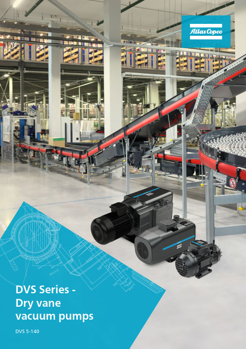
Robust Design:• Reliable graphite vanes• Construction without oil and oil filters• Modular design• Multiple operational features as standardAtlas Copco’s vacuum solutions continually build on a strong legacy of innovation and reliability. Our vacuum engineers and designers are always seeking to introduce newer technologies and revolutionize productivity for industrial markets across the globe. We keep in mind reduced carbon footprint and energy consumption, lower lifecycle costs, ease of maintenance and our customers productivity while designing and manufacturing our vacuum pumps.DVS Series – Dry vane vacuum pumpsWe introduce our new range of oil-free vacuum pumps – the DVS series. These are single-stage dry vane vacuum pumps which do not require oil to operate. This ensures a clean operation, free of emissions and no contamination to the process. These dry rotary vane vacuum pumps are designed to be robust, simple, clean, compact, and silent suited for rough industrial applications with high efficiency and competitive initial investment costs.We offer dry vane vacuum pumps with nominal suction flow from 5 m³/h to 140 m³/h and ultimate vacuum level up to 120-150 mbar(a) depending on the model.Working principleThe DVS series are positive displacement vacuum pumps. The design and technology maximize the level of vacuum created while minimizing energy consumption and wear and tear. Due to the rotation of the rotor the vanes inside slide. The vacuum is generated with minimum friction due to the high quality graphite alloy. These features together with the premium construction ensure a reliable pump and a long time between maintenance. Exhaust air goes through an air cooler to reduce the discharged air temperature.The design of the DVS series combined with Atlas Copco’s expertise ensures easy maintenance. Atlas Copco’s highly resistant graphite vanes help achieve maximum durability with minimal wear and tear.Included as standard on all models:• inside inlet filter • non-return valve • exhaust silencer• noise containing canopy (from DVS 16-140)• energy efficient IE3 electric motor (from DVS 16-140)Efficient:• Direct drive • Low noise level • Small footprint•Long time between serviceClean:• Dry and oil-free vacuum technology • Air-cooled pump• Oil-free operations with no emissions and contamination for your processFeature and benefitsDVS 5DVS 85P u m p ın g s p e e d (m /h )Vacuum level (mbar(a))DVS 16 50Hz DVS 40 50HzDVS 16 60Hz DVS 40 60HzP u m p ın g s p e e d (m /h )Vacuum level (mbar(a))2040608010012014016001002003004005006007008009001000P u m p ın g s p e e d (m /h )Vacuum level (mbar(a))012345678910020040060080010001200DVS 100 50Hz DVS 100 60Hz DVS 140 50Hz P u m p ın g s p e e d (m /h )Vacuum level (mbar(a))010203040506070809010001002003004005006007008009001000DVS 25 50Hz DVS 140 60HzDVS 25 60HzDVS 60 50Hz DVS 5 50Hz DVS 60 60Hz DVS 5 60HzDVS 80 50Hz DVS 8 50Hz DVS 8 60HzDVS 80 60Hz ApplicationsTechnical specificationsPerformance curvesDVS 16DVS 40DVS 80DVS 25DVS 60DVS 100Regular scheduled maintenance can identify potential problems before they occur and plans can be structured around your individual production situation. Preventive Care enables cost management as you can plan your maintenance costs in advance. In this way, expenses associated with unplanned downtime are minimized.Our vacuum specialists are well-trained and experts in the field. They will help you to improve uptime and protect your processes. Regular maintenance conducted by one of our vacuum specialists reduces the risk of deterioration. Damaged or worn parts will be replaced with genuine Atlas Copco spare parts to protect your investment and increase the lifespan of your vacuum pumps.We use genuine Atlas Copco spare parts and oil and our services are conducted by vacuum specialists according to manufacturer’srecommendations. This enhances your vacuum pump performance, reducing the risk of downtime and enabling your production to run more smoothly.Service support and maintenanceWe take over the maintenance planning and responsibility for servicing your vacuum pump on a regular basis. Our Preventive Care plan is tailored to your pump’s needs. As your pump is serviced with the latest technology, high levels of energy efficiency are achieved. We will also optimize service events toreduce your total cost of ownership and increase your productivity. This allows you to focus fully on your production.Cost-effectiveapproachMaximize lifetime of your vacuum pumpsReliability meetsnon-stop productivityDVS 140AccessoriesComplete service withour Preventive Care planAtlas Copco AB /vacuum 699623693©223,AtlasCopco.Designsandspecificationsaresubjecttochangewithoutnoticeorobligation.Readallsafetyinstructionsinthema。
莱宝真空 Turbolab 80 型涡旋分子泵系统 使用说明书
TURBOLAB 80 Turbomolecular pump system with dry compressing backing pumpOperating Instructions GA501591_002_A2Material number501591VxxxContents1D scription 31.1Ordering Information 31.2Supplied Equipment 31.2.1Pump System Components 31.2.2Accessories 31.3Technical Data 42Conn ctions 42.1Conforming Utilisation 53Op ration 63.1Electrical Connection 63.2Switching the System on 73.3Changing the Default Settings of the System 73.3.1 Selecting the HV Gauge Head 83.3.2 Selecting the Forevacuum Gauge Head 93.3.3 Selecting the Language 93.4Commissioning the System 103.4.1 Changing the Display Settings 113.4.2 Pressure History 113.4.3 Operating Hours 113.4.4 Venting Valve 123.4.5 Pressure Units 133.5Shutting the System Down 133.6Operating Information 134Spare Parts 145Options 141 DescriptionDescribed in these Operating Instructions is the equipment and operation of the turbomolecular pump system TURBOLAB 80.1.1 Or d ering InformationTURBOLAB 80, DN63ISO-K 501591V1xyz*TURBOLAB 80, DN63CF 501591V2xyz**xyz indicate the precise version of the system together with the possible options.1.2 Supplie d EquipmentTURBOLAB 80Mains cord 230V/1ph/50HzOperating Instructions for the pump systemOperating Instructions for the turbomolecular pumpInlet screen for the turbomolecular pump1.2.1 Pump System Componentsx Turbomolecular pump SL80x Frequency converter TURBO.DRIVE 400x24 V DC power supply unitx Diaphragm pumpx Control unit1.2.2 AccessoriesOptional accessories for the pump systems are:x High vacuum gauge ITR90x High vacuum gauge PTR90x Forevacuum gauge TTR91x Venting valve1.3 Technical DataPumping spee d for N2 60 l/sAttainable ultimate pressure range 10-7 mbar *Run-up time for the turbomolecular pump 1.5 minutesPumping speed of the diaphragm pump 0.7 m³/hUltimate pressure of the diaphragm pump 3 mbarMains voltages 100-240V, 1ph,50-60HzMain fuses (at the main switch) 10 ADimensions 255 x 355 x 355 mmAmbient conditionsTemperature 0 – 35°CHumi d ity 5 – 95%,non-condensingWeight 14.5 kg* At ambient temperature 20°C.2 ConnectionsNever expose any parts of the body to the vacuum.The turbomolecular pump must be firmly attached usingbolts.If the pump is not affixed adequately, parts from inside thepump may come loose and fly around should the pumpseize. Never operate the pump system without having flanged it to the vacuum chamber first in the course of a benchtop test, for example.After a mains power failure in the pump may run up automatically as soon as the mains power returns.If the pump has been pumping hazardous gases before, then introduce suitable precautions before opening the intake or exhaust connections.If necessary, wear protection gloves, breathing protection or protective clothing and work under a fume hood.The turbomolecular pump system is not suited for pumping of dusty, aggressive or corrosive media.The turbomolecular pump system must only be uninstalled when not in operation.Accelerating forces must be avoided or reduced to such a level that the rotor unit is not excited by vibrations. In critical applications consult our application department first.The pump must be only opened by persons duly authorised by Leybold.2.1 Conforming UtilisationVacuum pump systems as described in the catalogue are not suited for pumping of:Ŷҏo xygen at levels exceeding the concentration present in theatmosphere,Ŷҏh azardous gases,Ŷҏe asily flammable, explosive or toxic gases,Ŷҏe xtremely aggressive or corrosive mediaŶҏl iquidsŶҏo r solid materials.The operator is responsible for assessing the danger potential of the process media which as to their composition differ from the normal atmosphere.3 Operation3.1 Electrical ConnectionWarningRisk of suffering injury!During all connection work deenergise mains power lines(lockout/tag out). The electrical connections must only beprepared by a trained electrician as, for example, in accordancewith EN 50110-1.The mains connection of the pump system can be found on the right at thebottom on the rear of the pump system. There also the main switch can befound. The main fuse is located behind a cover panel on the main switch.Main switchMains connection Connectionfor the highvacuumgaugeFuses for theturbomolecular pump,forepump and controlunit3.2 Switching the System onThe TURBOLAB 80 is switched on through the main switch on the rear ofthe housing.After switching on, the display will indicate: Self-Test PassedAfter a few seconds the display changes to the welcome screenBy pressing the pushbutton within 15 seconds, the default settings of thesystem can be changed, see Chapter 3.3.3.3 Changing the Default Settings of the SystemWelcomescreenDepending on which high vacuum gauge and which forevacuum gauge hasbeen connected to the TURBOLAB 80 the software must be set upaccordingly. This is done through the default settings. In order to enter the mode of the default settings, the pushbutton mustbe pressed within 10 seconds.Then it is possible to select one after the other the type of high vacuumgauge, the type of forevacuum gauge and the language. After the 10 seconds have elapsed without operating the pushbutton thedisplay automatically changes to the operating display mode. In order toredisplay the welcome screen and enter the mode of the default settings, thepump system must be switched off and on again at its main switch.Display/change thedefault settings3.3.1 Selecting the HV Gauge Head After having pressed the pushbutton in the welcome screen (seeChapter 3.3) the display will indicate the enabled settings for the highvacuum measurement. Example:Depending on how the TURBOLAB 80 has been equipped on delivery, thefollowing will be indicated:For systems without a gauge head HV-MESSUNG OHNEFor systems with an ITR90: HV-MESSUNG ITR90For systems with a PTR90: HV-MESSUNG PTR90In order to change the setting, the ENTER pushbutton must be pressed.Thereafter the bottom area with the information on the high vacuum gauge(OHNE / ITR90 / PTR90) is displayed with a black background. Through the pushbuttons and a different setting can be selected.Possible settings:x OHNE (no high vacuum gauge)x ITR90x PTR90By pressing the ENTER pushbutton once more the setting is enabled.HV – MESSUNGOHNE ENTER pushbutton Pushbuttons for selecting the possible parameters3.3.2 Selecting the Forevacuum Gauge HeadBy pressing the pushbutton the display will indicate the enabled settings for the forevacuum measurement.Example:VV – MESSUNGOHNEDepending on how the TURBOLAB 80 has been equipped on delivery, the following will be indicated:For systems without a gauge head: VV-MESSUNG OHNEFor systems with a TTR91: VV-MESSUNG TTR91In order to change the setting, the ENTER pushbutton must be pressed. Thereafter the bottom area with the information on the forevacuum gauge (OHNE / TTR91) is displayed with a black background.Through the pushbuttons and a different setting can be selected. Possible settings:x OHNE (no forevacuum gauge head)x TTR91By pressing the ENTER pushbutton once more the setting is enabled.3.3.3 Selecting the LanguageWhen pressing the pushbutton once more the display will indicate the currently enabled language.Example:SPRACHEDeutschUpon delivery of the TURBOLAB 80 the language has been set to German. In order to change the setting, the ENTER pushbutton must be pressed. Thereafter the bottom area with the information on the language (Deutsch / Italiano / Francaise / English) is displayed with a black background. Through the pushbuttons and a different setting can be selected.Possible settings:x Deutschx Italianox Francaisex EnglishBy pressing the ENTER pushbutton once more the setting is enabled. After pressing the pushbutton once more, the welcome screen will bedisplayed again which after approximately 10 seconds automaticallychanges to the operating mode display.3.4 Commissioning the SystemAfter the display has switched over to the operating mode display thefollowing is indicated.If no high vacuum or forevacuum gauge has been selected, then nothing willbe displayed in the corresponding field. Through the pushbutton next to “ON” the pump system can be started.The display will then change to “OFF“ and the operating status will indicate“VV EIN ”.As soon as the factory default cut-in pressure of 20 mbar has been attained,the turbomolecular pump will start automatically and the operating displaywill change to “TMP HOCHLAUF ”.After run-up has completed, the operating status “HV ERREICHT ” will bedisplayed.Optional driving High vacuum pressure Forevacuum pump Display change through the pushbuttons and Current drawn andfrequency of the turbomolecular pump Operatingstatus3.4.1 Changing the Display SettingsDuring operation of the TURBOLAB 80 different display settings can be set up through the pushbutton .The following displays are available which may be selected by pressing the pushbutton once more and alternatively backwards through the pushbutton.3.4.2 Pressure HistoryThe pressure history may be displayed by way of the pumpdown curve overthe last eight minutesThe pressure unit will be the unit which has been set up.3.4.3 Operating HoursForevacuum pump operating hoursHigh vacuum pump operating hoursGenerally the number of operating hours for the high vacuum pump will be higher than those for the forevacuum pump, since the high vacuum pump has been subjected to an endurance test in the factory over several hours. This time is recorded by the turbomolecular pump. The displayed value is composed of the number of operating hours during the test run in the factory plus the number of operating hours of the pump system.The number of operating hours for the forevacuum pump will only indicate the number of operating hours for the pump system.Pressure (Value as exponent)Example: -3 = 10E-3Time (min)STUNDEN VV 000006.7 hSTUNDEN HV 000024.9 h3.4.4 Venting ValveThe venting valve can be set up to fulfil different functions .Operating setting Position FunctionAutoOPEN or CLOSED60 seconds after theturbomolecular pump has been switched off and decelerated, the venting valve opens for two minutes. Thereafter it closes automatically.Manual CLOSEDThe pump system is not vented. ManualOPEN 60 seconds after theturbomolecular pump has been switched off, venting is effected. Thereafter the venting valve remains open. When the pump system starts, the venting valve closes.BELUEFTUNG AutoOperating setting automatic or manual (Change this setting throughand, and thereafter confirm with)Position of the venting valve after switching the system off AUF or ZU3.4.5 Pressure UnitsDifferent pressure units can be set upEINHEITmbarThrough the pushbuttons and the pressure unit can be changed, thereafter confirm through .Possible pressure units:x mbarx Pax TorrBy pressing the pushbutton the operating display is displayed once more.3.5 Shutting the System DownTo shut down the system, is selected with the pushbutton next to it.The display will indicate the message “TMP BREMST”.After the turbomolecular pump has arrived at standstill, the display will change to “AUS”.3.6 Operating InformationWith connected gauge heads, only automatic operation is possible.Without gauge heads, only manual operation is possible.To read out the parameters on a PC please contact Oerlikon Leybold Vacuum, Cologne.4 SparePartsFuses 10 A P/N 500 007 9556504920 Controller with Software P/N5 OptionsVenting valve kit P/N 6504899 Adapter for PTR gauge head P/N 6504112DescriptionEC - Declaration of ConformityThe manufacturer: Oerlikon Leybold Vacuum GmbHBonner Straße 498D-50968Cologne347-0Tel.:+49(0)221************************herewith declares that the following product:Product designation: Turbomolecular pump systemType designation: TURBOLAB 80 Full FeaturedPart number: 501591Vxxxxcomplies with all pertinent regulations of the Directive on Machinery (2006/42/EC).Furthermore the machinery complies with all regulations of the Directive Electrical Equipment(2006/95/EC) and Electromagnetic Compatibility(2004/108/EC).The following harmonised standards have been applied:EN 1012-2, 1996 Compressors and vacuum pumps - Safety requirements - Part 2: VacuumpumpsEN 60204-1, 2006 Safety of machinery - Electrical equipment of machines – Part 1: GeneralrequirementsEN 61010-1 2002 Safety of electrical measure, control and laboratory equipmentEN 61000-6-4, 2007 Electromagnetic compatibility (EMC) - Part 6-4: Generic standards -Emission standard for industrial environmentsEN 61000-6-2 2005 Electromagnetic compatibility (EMC) - Part 6-2: Generic standards -Immunity for industrial environmentsDocumentation officer Herbert EtgesTel.: +49(0)221 347-0Fax: + 49(0)221 347 1250****************************************Oerlikon Leybold Vacuum GmbHBonner Straße 498 , D-50968 KölnCologne, August 04, 2010 Cologne, August 04, 2010_______________________________ ______________________UdelhovenHaraldHans-JürgenBlumHead of Oerlikon Leybold Vacuum :solutions Senior ManagerHead of Quality ManagementSales and ServiceGermanyOerlikonLeybold Vacuum GmbH Bonner Strasse 498D-50968 ColognePhone: +49-(0)221-347 1234Fax: +49-(0)221-3471245*************************OerlikonLeybold Vacuum GmbHSales Area North/EastBranch Office BerlinIndustriestr. 10bD-12099 BerlinPhone: +49-(0)30-435 609 0Fax: +49-(0)30-435 609 10****************************OerlikonLeybold Vacuum GmbHSales Area South/Southwest Branch Office MunicSendlinger Strasse 7D-80331 MunicPhone: +49-(0)89-357 33 9-10 Fax: +49-(0)89-357 33 9-33**************************** service.vacuum.mn@OerlikonLeybold Vacuum GmbHSales Area West & Benelux Bonner Strasse 498D-50968 ColognePhone: +49-(0)221-347 1270Fax: +49-(0)221-3471291****************************OerlikonLeybold Vacuum GmbH Service Competence Center Emil-Hoffmann-Strasse 43D-50996 Cologne-SuerthPhone: +49-(0)221-347 1439Fax: +49-(0)221-3471945******************************OerlikonLeybold Vacuum GmbHMobil Customer ServiceEmil-Hoffmann-Strasse 43D-50996 Cologne-SuerthPhone: +49-(0)221-347 1765Fax: +49-(0)221-3471944******************************OerlikonLeybold Vacuum GmbH, DresdenZur Wetterwarte 50, Haus 304D-01109 DresdenService:Phone: +49-(0)351-88 55 00Fax: +49-(0)351-88 55 041***************************OerlikonLeybold Vacuum USA Inc. 5700 Mellon RoadExport, PA 15632Phone: +1-724-327-5700 Fax: +1-724-325-3577***************************EuropeBelgiumOerlikon Leybold VacuumNederland B.V.Belgisch bijkantoorLeuvensesteenweg 542-9AB-1930 ZaventemSales:Phone: +32-2-711 00 83Fax: +32-2-7208338****************************Service:Phone: +32-2-711 00 82Fax: +32-2-7208338******************************FranceOerlikonLeybold Vacuum France S.A.7, Avenue du QuébecZ.A. Courtaboeuf 1 - B.P. 42F-91942 Courtaboeuf CedexSales and Service:Phone: +33-1-69 82 48 00Fax: +33-1-69 07 57 38****************************OerlikonLeybold Vacuum France S.A.Valence Factory640, Rue A. Bergès - B.P. 107F-26501 Bourg-lès-Valence CedexPhone: +33-4-75 82 33 00Fax: +33-4-75 82 92 69***************************Great BritainOerlikonLeybold Vacuum UK LTD.Unit 2Silverglade Business ParkLeatherhead RoadUK-Chessington, Surrey KT9 2QLSales:Phone: +44-13-7273 7300Fax: +44-13-72737301****************************Service:Phone: +44-20-8971 7030Fax: +44-20-89717003******************************ItalyOerlikonLeybold Vacuum Italia S.p.A.8, Via TrasimenoI-20128 MilanoSales:Phone: +39-02-27 22 31Fax: +39-02-27 20 96 41****************************Service:Phone: +39-02-27 22 31Fax: +39-02-27 22 32 17******************************OerlikonLeybold Vacuum Italia S.p.A.Field Service BaseZ.I. Le CapanneI-05021 Acquasparta (TR)Phone: +39-0744-93 03 93Fax: +39-0744-944287******************************NetherlandsOerlikon Leybold VacuumNederland B.V.Computerweg 7NL-3542 DP UtrechtSales and Service:Phone: +31-346-58 39 99Fax: +31-346-58 39 90**********************************************************SpainOerlikonLeybold Vacuum Spain, S.A.C/ Huelva, 7E-08940 Cornellà de Llobregat(Barcelona)Sales:Phone: +34-93-666 46 16Fax: +34-93-666 43 70****************************Service:Phone: +34-93-666 49 51Fax: +34-93-685 40 10SwedenOerlikon Leybold VacuumScandinavia ABBox 9084SE-40092 GöteborgSales and Service:Phone: +46-31-68 84 70Fax: +46-31-68 39 39***************************Visiting/delivery address:Datavägen 57BSE-43632 AskimSwitzerlandOerlikonLeybold Vacuum Schweiz AGLeutschenbachstrasse 55CH-8050 ZürichSales:Phone: +41-044-308 40 50Fax: +41-044-302 43 73****************************Service:Phone: +41-044-308 40 62Fax: +41-044-308 40 60AmericaUSAOerlikonLeybold Vacuum USA Inc.5700 Mellon RoadExport, PA 15632Phone: +1-724-327-5700Fax: +1-724-325-3577***************************Sales:Eastern & Central time zonesPhone: +1-724-327-5700Fax: +1-724-733-1217Pacific, Mountain, Alaskan &Hawaiian time zonesPhone: +1-480-752-9191Fax: +1-480-752-9494Service:Phone: +1-724-327-5700Fax: +1-724-733-3799OerlikonLeybold Vacuum GmbHBonner Strasse 498D-50968 ColognePhone: +49-(0)221-347 0Fax: +49-(0)221-347 1250************************AsiaP.R. ChinaOerlikonLeybold Vacuum (Tianjin)International Trade Co., Ltd.Beichen EconomicDevelopment Area (BEDA),Shanghai RoadTianjin 300400ChinaSales and Service:Phone: +86-22-2697 0808Fax: +86-22-26974061Fax: +86-22-26972017****************************OerlikonLeybold Vacuum(Tianjin) Co., Ltd.Beichen EconomicDevelopment Area (BEDA),Shanghai RoadTianjin 300400ChinaSales and Service:Phone: +86-22-2697 0808Fax: +86-22-26974061Fax: +86-22-26972017***************************OerlikonLeybold Vacuum (Tianjin)International Trade Co., Ltd.Shanghai Branch:Add: No. 3376 Futedong San Rd.Waigaoqiao FTZShanghai 200131ChinaSales and Service:Phone: +86-21-5064-4666Fax: +86-21-5064-4668***************************OerlikonLeybold Vacuum (Tianjin)International Trade Co., Ltd.Guangzhou Office andService Center1st F, Main Building,Science City Plaza,No.111 Science Revenue,Guangzhou Science City(GZSC) 510663, Guangzhou,ChinaSales:Phone: +86-20-22323980Fax: +86-20-22323990***************************OerlikonLeybold Vacuum (Tianjin)International Trade Co., Ltd.Beijing Branch:1-908, Beijing Landmark Towers8 North Dongsanhuan RoadChaoyang DistrictBeijing 100004ChinaSales:Phone: +86-10-6590-7622Fax: +86-10-6590-7607IndiaOerlikonLeybold Vacuum India Pvt Ltd.EL-22, J BlockMIDC BhosariPune 411026IndiaSales:Phone: +91-20-3061 60000Fax: +91-20-27121571****************************JapanOerlikonLeybold VacuumJapan Co., Ltd.Head OfficeTobu A.K. Bldg. 4th Floor23-3, Shin-Yokohama3-chomeKohoku-ku, Yokohama-shiKanagawa-ken 222-0033Sales:Phone: +81-45-471-3330Fax: +81-45-471-3323OerlikonLeybold VacuumJapan Co., Ltd.Osaka Sales Office5-13, Kawagishi-choSuita-chiOsaka-fuPhone: +81-6-4860-2212Fax: +81-45-471-3323OerlikonLeybold VacuumJapan Co., Ltd.Tsukuba Technical S.C.Tsukuba Minami DaiichiKogyo Danchi21, Kasumi-no-Sato,Ami-machi, Inashiki-gunIbaraki-ken, 300-0315Service:Phone: +81-29-889-2841Fax: +81-29-889-2838KoreaOerlikonLeybold Vacuum Korea Ltd.3F.Jellzone 2 Tower159-4 Jeongja-Dong, Bundang-Gu,Sungnam-Si, Gyeonggi-Do,Korea 463-834Sales:Tel.: +82-31-785-1367Fax: +82-31-785-1359Service:Tel.: +82-41-589-3035Fax: +82-41-588-0166SingaporeOerlikonLeybold VacuumSingapore Pte Ltd.1 Science Park RoadSingapore Science Park 2#02-12 Capricorn BuildingSingapore 117528Sales und Service:Tel.: +65-63037000Fax: +65-67730039***************************TaiwanOerlikonLeybold Vacuum Taiwan Ltd.No 416-1, Sec. 3Chung-Hsin Rd., Chu-TungHsin-Chu, Taiwan, R.O.C.Sales and Service:Phone: +886-3-500 1688Fax: +886-3-5833999****************************。
旋涡泵设计说明书

自吸旋涡泵的设计学生姓名:指导老师:摘要旋涡泵就是靠旋转叶轮对液体的作用力,在液体运动方向上给液体以冲量来传递动能以实现输送液体。
旋涡泵是一种高压泵,清水泵。
旋涡泵的叶轮为一等厚圆盘,在它外缘的两侧有很多径向小叶片。
在与叶片相应部位的泵壳上有一等截面的环形流道,整个流道被一个隔舌分成为吸、排两方,分别与泵的吸、排管路相联。
泵内液体随叶轮一起回转时产生一定的离心力,向外甩入泵壳中的环形流道,并在流道形状的限制下被迫回流,重新自叶片根部进入后面的另一叶道。
因此,液体在叶片与环形流道之间的运动迹线,对静止的泵壳来说是一种前进的螺旋线;而对于转动的叶轮来说则是一种后退的螺旋线。
旋涡泵即因液体的这种旋涡运动而得名。
液体能连续多次进入叶片之间获取能量,直到最后从排出口排出。
旋涡泵的工作有些像多级离心泵,但旋涡泵没有像离心泵蜗壳或导叶那样的能量转换装置。
旋涡泵主要是通过多次连续作功的方式把能量传递给液体,所以能产生较高的压力。
在能量传递过程中,由于液体的多次撞击,能量损失较大,泵的效率较低,一般为20~50%。
旋涡泵只适用于要求小流量(1~40米3/时)、较高扬程(可达250米)的场合,如消防泵、飞机加油车上的汽油泵、小锅炉给水泵等。
旋涡泵可以输送高挥发性和含有气体的液体,但不应用来输送粘度大于7帕·秒的较稠液体和含有固体颗粒的不洁净液体。
旋涡泵的特点流量小,扬程高,具有自吸功能,可用来输送粘度小于5度E的无固体颗粒及其类似于水的液体。
过流部件还有不锈钢等材质可用来输送酸、碱类有腐蚀性的液体。
输送介质温度为-20~+80度。
从结构可分为;单级、双级、多级;直联形式等。
在此次毕业设计任务及目标中我绘制25WB-30型漩涡泵设计图纸包括总装配图和各种零件图。
撰写设计论文,保质保量完成毕业设计任务, 设计论文内容合理、基本正确。
设计图纸基本符合生产和制造工艺,具有较高的可制造性;本次设计对漩涡泵特性及相似理和效率 以及流道设计对泵性能曲线影响的论的应用进行了学习并探讨。
CWB磁力旋涡泵使用说明书

上海沈泉泵阀制造有限公司■ 概 述是本公司在多年生产W 型旋涡泵的经验基础上进行改型设计的新型旋涡泵。
该系列泵采用磁力传动结构,无轴封,保证泵能点滴不漏地输送介质,通过多家用户使用证明,该系列泵既具有旋涡泵的小流量,高扬程的特点,又具有磁力泵无泄漏的优点,因而,深受用户的青睐。
泵的过流部件采用1Crl8Ni9Ti 不锈钢,可无泄漏输送易燃、易爆、剧毒等化学介质。
■ 特点1、高扬程、小流量,比转速一般小于40;2、结构简单、体积小、重量轻;3、具有自润滑回路,提高滑动轴承使用寿命;’4、增设冷却回路,及时带走磁涡流热;5、设有叶轮轴向间隙调节机构,可随时调整间隙,确保泵的长期正常运转。
6、随输送介质黏度增加,泵的效率急剧下降;因而介质黏度应不大于5×10⁻⁶m 2/s 。
■ 结构示意图1进出口接管 8止推环 2泵壳 9隔离套3密封垫10 内磁组件4泵盖组件 11 外磁组件 5叶轮 12 联接架 6轴承 13 底板 7轴14电机■ 型号与意义 例如:CWB磁力旋涡泵CWB磁力旋涡泵■ 性能参数表型号 流量(m 3/h)扬程 (m) 转速 (r/min)电机功率(kW) 效率 (%) 允许吸上 高度(m) 叶轮直径(mm) 重量(Kg)CWB20-20 0.72 20 2900 0.75 22 6 65 26 CWB20-40 0.72 40 2900 1.1 18 6 90 32 CWB20-65 0.72 65 2900 1.1 15 6 105 36 CWB25-25 1.44 25 2900 1.1 26 5 75 28 CWB25-40 1.44 40 2900 1.5 24 5 90 40 CWB25-75 1.44 75 2900 4 20 5 110 55 CWB32-30 2.88 30 2900 2.2 28 5 90 38 CWB32-50 2.88 50 2900 3 26 5 100 52 CWB32-75 2.88 75 2900 7.5 22 5 120 76 CWB32-120 2.88 120 2900 11 18 4.5 140 95 CWB40-40 5.4 40 2900 4 30 4 100 70 CWB40-90 5.4 90 2900 11 26 3.5 130 105 CWB50-45 9 45 2900 17.5 30 4 110 92 CWB65-5014.450290015353.5120158■ 安装尺寸图CWB磁力旋涡泵■ 安装尺寸表型号 ABCEF KLh HH1DNDD1 φdl φd2CWB20-20 31 210 86 12592200440801302J7020 90 65 13.511CWB20-40 43 210 58 1401022004588013028420 90 65 13.511CWB20-65 48 260 108 1401102004869015331320 105 75 13.513.5CWB25-25 45 210 104 1401202354628013033025 115 85 13.513.5CWB25-40 49 260 110 1401202354889015335325 115 85 13.513.5CWB25-75 25 328 93 19012824260611217538625 115 85 13.513.5CWB32-30 52 260 118 1401502905229015336832 140 100 13.517.5CWB32-5028 328 100 16015029061410016337832 140 100 1817.5CWB32-75 100 295 169 32015035668413221242J732 140 100 1817.5CWB32-120 96 486 173 38016041687816024046832 140 100 1817.5CWB40-40 30 328 104 19016031061811217544340 150 110 13.517.5CWB40-9096 486 173 38016041687816024050840 150 110 1817.5CWB50-45 104 295 177 3201J7035669213221246250 165 125 1817.5CWB65-5082 486 159 38019041687816024052065 185 145 1817.5■ 磁力泵的安装和使用(一)磁力泵应水平安装,不宜竖立,对于特殊要求垂直安装的场合,电机务必朝上。
- 1、下载文档前请自行甄别文档内容的完整性,平台不提供额外的编辑、内容补充、找答案等附加服务。
- 2、"仅部分预览"的文档,不可在线预览部分如存在完整性等问题,可反馈申请退款(可完整预览的文档不适用该条件!)。
- 3、如文档侵犯您的权益,请联系客服反馈,我们会尽快为您处理(人工客服工作时间:9:00-18:30)。
自吸旋涡泵的设计学生姓名:指导老师:摘要旋涡泵就是靠旋转叶轮对液体的作用力,在液体运动方向上给液体以冲量来传递动能以实现输送液体。
旋涡泵是一种高压泵,清水泵。
旋涡泵的叶轮为一等厚圆盘,在它外缘的两侧有很多径向小叶片。
在与叶片相应部位的泵壳上有一等截面的环形流道,整个流道被一个隔舌分成为吸、排两方,分别与泵的吸、排管路相联。
泵内液体随叶轮一起回转时产生一定的离心力,向外甩入泵壳中的环形流道,并在流道形状的限制下被迫回流,重新自叶片根部进入后面的另一叶道。
因此,液体在叶片与环形流道之间的运动迹线,对静止的泵壳来说是一种前进的螺旋线;而对于转动的叶轮来说则是一种后退的螺旋线。
旋涡泵即因液体的这种旋涡运动而得名。
液体能连续多次进入叶片之间获取能量,直到最后从排出口排出。
旋涡泵的工作有些像多级离心泵,但旋涡泵没有像离心泵蜗壳或导叶那样的能量转换装置。
旋涡泵主要是通过多次连续作功的方式把能量传递给液体,所以能产生较高的压力。
在能量传递过程中,由于液体的多次撞击,能量损失较大,泵的效率较低,一般为20~50%。
旋涡泵只适用于要求小流量(1~40米3/时)、较高扬程(可达250米)的场合,如消防泵、飞机加油车上的汽油泵、小锅炉给水泵等。
旋涡泵可以输送高挥发性和含有气体的液体,但不应用来输送粘度大于7帕·秒的较稠液体和含有固体颗粒的不洁净液体。
旋涡泵的特点流量小,扬程高,具有自吸功能,可用来输送粘度小于5度E的无固体颗粒及其类似于水的液体。
过流部件还有不锈钢等材质可用来输送酸、碱类有腐蚀性的液体。
输送介质温度为-20~+80度。
从结构可分为;单级、双级、多级;直联形式等。
在此次毕业设计任务及目标中我绘制25WB-30型漩涡泵设计图纸包括总装配图和各种零件图。
撰写设计论文,保质保量完成毕业设计任务, 设计论文内容合理、基本正确。
设计图纸基本符合生产和制造工艺,具有较高的可制造性;本次设计对漩涡泵特性及相似理和效率 以及流道设计对泵性能曲线影响的论的应用进行了学习并探讨。
通过分析转速ns对比试验,阐述泵性能变化规律。
推导出旋涡泵直径D,出口直径d等计算方法公式。
关键字:旋涡泵设计创新vortex pump designStudent: Advisor:AbstractThe vortex pump is by the force of the rotating impeller on the liquid, the impulse to pass kinetic energy to achieve the transport liquid to the liquid in the direction of liquid movement. V ortex pump is a high-pressure pump, water pump. V ortex pump impeller for a first-class thick disk, and a lot of small radial blades in its outer edge on both sides. Flow in first-class section of the ring and leaves the corresponding parts of the pump casing, the entire flow channel is separated from a tongue points to become sucked row the two sides, respectively, and the pump suction and exclusive piping associated. Liquid with pump impeller with rotary centrifugal force, thrown out into the pump casing in the annular flow channel, and under the restrictions of the shape of the flow channel was forced to reflux, and re-enter from the blade root behind the other blade channel. Therefore, the movement traces of the liquid between the blades and annular flow channel for the stationary pump casing is a forward helix; rotating impeller is a backward spiral. V ortex pump that got its name due to this vortex motion of the liquid. The liquid can repeatedly enter the blade between access to energy, until finally discharged from the outlet. V ortex pump, somewhat like a multi-stage centrifugal pump, vortex pump is not like a centrifugal pump volute or guide vanes as energy conversion devices.V ortex pump through multiple consecutive successful energy transfer to the liquid, they are able to produce high pressure. Liquid repeatedly hit in the process of energy transfer, energy loss, low efficiency of the pump, generally 20 to 50 percent. V ortex pump is only applicable to the requirements of the small flow (1 to 40 m³/ h) and higher lift (up to 250 m) of the occasions, such as fire pumps, aircraft refueling vehicle fuel pump, a small boiler feed pump. The vortex pump can transport highly volatile and gas-containing liquid, but should not be used to transport the viscosity of gr eater than 7 Pa • sec a more viscous liquid containing solid particles unclean liquids. The characteristics of the vortex pump flow, head high, with self-priming function can be used for the transmission of less than 5 degrees E no solid particles and water-like liquid viscosity. Flow parts, stainless steel and other materials used for the transmission of acid, alkali, corrosive liquids. The transmission medium temperature -20 to +80 degrees. From the structurecan be divided into; single-stage, dual-stage, multi-level; Direct form.In the graduation project tasks and goals, I draw 25WB-30 whirlpool pump design drawings including the general assembly drawings and parts diagram. Write a design paper, the quality and quantity to complete the graduation design task, design thesis is basically correct. Design drawings in line with production and manufacturing processes, with high manufacturability; the design of the whirlpool pump characteristics and the application of similarity theory to learn and explore. By analyzing the speed ns and efficiency, as well as the flow channel design on the comparative test of the influence of pump performance curves to explain the variation of pump performance. Deduced vortex pump diameter D, the outlet diameter d calculation formula.Keywords: V ortex pump; design; innovation;目录摘要 (i)Abstract (ii)目录 (iiii)第一章绪论 (1)1.1旋涡泵概论 (1)1.2旋涡泵发展趋势 (2)第二章旋涡泵 (4)2.1旋涡泵的结构特征 (4)2.2旋涡泵的基本参数 (4)2.3旋涡泵的分类和结构形式 (5)第三章 25w-30漩涡泵工作设计计算 (7)3.1设计计算条件及公式 (7)3.2 25w-30旋涡泵设计技术指标及设计计算 (10)3.2.1旋涡泵的指标 (10)3.2.2旋涡泵的参数公式 (10)3.3轴的结构设计 (12)3.4电机的选择 (13)3.4.1 Y系列小型单相异步电动机 (13)3.4.2 系列小型单相异步电动机的安装及外形尺寸 (14)3.5载荷计算 (14)3.6键的选择计算 (14)3.7 轴承的选用 (16)3.8轴的校核计算 (18)3.8密封的选择 (18)第四章总结 (20)参考文献 (21)致谢 (22)第一章绪论1.1旋涡泵概论旋涡泵(也称涡流泵)是一种叶片泵。