TS2250型深孔镗床的优势与参数介绍
2250产线知识

●高炉炼铁高炉生产时从炉顶装入铁矿石、焦炭、造渣用熔剂(石灰石),从位于炉子下部沿炉周的风口吹入经预热的空气.在高温下焦炭(有的高炉也喷吹煤粉、重油、天然气等辅助燃料)中的碳同鼓入空气中的氧燃烧生成的一氧化碳和氢气,在炉内上升过程中除去铁矿石中的氧,从而还原得到铁。
炼出的铁水从铁口放出。
铁矿石中未还原的杂质和石灰石等熔剂结合生成炉渣,从渣口排出。
产生的煤气从炉顶排出,经除尘后,作为热风炉、加热炉、焦炉、锅炉等的燃料。
高炉冶炼的主要产品是生铁,还有副产高炉渣和高炉煤气。
●转炉炼钢转炉炼钢(converter steelmaking)是以铁水、废钢、铁合金为主要原料,不借助外加能源,靠铁液本身的物理热和铁液组分间化学反应产生热量而在转炉中完成炼钢过程。
转炉按耐火材料分为酸性和碱性,按气体吹入炉内的部位有顶吹、底吹和侧吹;按气体种类为分空气转炉和氧气转炉.碱性氧气顶吹和顶底复吹转炉由于其生产速度快、产量大,单炉产量高、成本低、投资少,为目前使用最普遍的炼钢设备.转炉主要用于生产碳钢、合金钢及铜和镍的冶炼.●炼铁2座4150 m3高炉,高炉利用系数2。
2 t/m3.d卡鲁金顶燃式热风炉系统无钟炉顶装料系统【高炉利用系数是衡量高炉炼铁生产率的一项重要技术经济指标。
利用系数值越高,表示高炉生产率越高.在中国以每立方米高炉有效容积1昼夜的合格生铁产量表示,计算式如下:利用系数=高炉日产量/高炉容积ηV=P/V式中ηV为高炉利用系数,t/(m3·d);P为高炉1昼夜生铁产量,t;V为高炉有效容积,m 。
d为1天】●铁水预处理3 套KR法脱硫装置[S ]含量≤50 ppm (ppm是浓度单位(百万分之一))如果ppm换算成百分号“%”为:1ppm=0.0001%【KR法最早是由日本1965年开发的,它是将浇注耐火材料并经过烘烤的十字形搅拌头,浸入铁水包熔池一定深度,利用在大型搅拌器激烈搅拌作用下产生的漩涡,使氧化钙或碳化钙基脱硫粉剂与铁水充分接触反应,达到脱硫目的.其优点是动力学条件优越,金属损失少,有利于采用廉价的脱硫剂如CaO,脱硫效果比较稳定,效率高(脱硫可至≤0。
镗床

二、镗刀
• 镗刀是指在镗床上用以镗孔的刀具。
1.常用镗刀的类型、结构和特点
(1)单刃镗 所示的单刃镗刀为镗盲孔用的盲孔镗刀, 所示的单刃镗刀为镗通孔用的通孔镗刀。
(2)双刃镗刀 双刃镗刀就是镗刀的两端有一对对称的 切削刃同时参与切削,切削时可以消除径向切削力对镗杆 的影响,工件孔径的尺寸精度由镗刀来保证。双刃镗刀分 为固定式和浮动式两种。固定式镗刀块及其安装如图8-12
——适用于批量生产的零件加工及位置精度要求较高的 孔的加工。
三、常用镗床
1、卧式铣镗床
工作台卧式铣镗床 的特点:
——广泛 使用于各 种常规精 度的单件 或小批量 的孔加工。
尾立柱
经向导轨
后支承
主轴箱
上滑座
尾筒
下滑座
床身
2、坐标镗床
顶梁 主轴箱 立柱 横梁 工作台 床身 主轴 立柱
8-12所示。
三、镗孔
(1)镗孔是对锻出,铸出或钻出孔的进一步加工,镗孔可扩 大孔径,提高精度,减小表面粗糙度,还可以较好地纠正来孔轴 线的偏斜。
(2)镗孔加工可以分为粗镗、半精镗和精镗。 精镗孔的尺寸精度可达IT8~IT7,表面粗糙度Ra值1.6~0.8μm。 (3)镗孔可以分为一般镗孔和深孔镗孔, 一般镗孔在普通车床就可以,把镗刀固定在车床尾座或者固 定在小刀架上都可以。 深孔镗孔需要专用的深孔钻镗床,镗刀要加上镗秆,还要加 上液压泵站利用冷却液把铁屑排除。
a) 镗刀镗孔; b)双镗刀镗同轴孔; c)悬伸镗刀 镗大直径孔; d)镗轴装端铣刀铣平面; e)平旋盘 上装车刀车内沟槽; f)平旋盘上装车刀车端面;
二、镗削加工的特点
1)镗孔是对已铸、锻、钻的孔进行加工,以扩大孔径、 提高精度、降低表面粗糙度以及孔位置的纠偏; 2)镗削加工的主运动是镗刀的旋转运动,进给运动可 以是主轴的轴向或经向移动,也可以是工作台的纵向或 横向移动; 3)镗削刀具结构简单、种类多样,具有较好的通用性, 但镗削加工(特别是单刃镗刀加工)生产效率较低;
深孔钻镗床设备优势特点
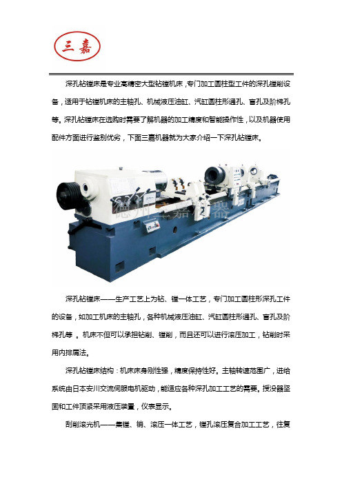
深孔钻镗床是专业高精密大型钻镗机床,专门加工圆柱型工件的深孔镗削设备,适用于钻镗机床的主轴孔、机械液压油缸、汽缸圆柱形通孔、盲孔及阶梯孔等。
深孔钻镗床在选购时需要了解机器的加工精度和智能操作性,以及机器使用配件方面进行鉴别优劣,下面三嘉机器就为大家介绍一下深孔钻镗床。
深孔钻镗床——生产工艺上为钻、镗一体工艺,专门加工圆柱形深孔工件的设备,如加工机床的主轴孔,各种机械液压油缸、汽缸圆柱形通孔、盲孔及阶梯孔等。
机床不但可以承担钻削、镗削,而且还可以进行滚压加工,钻削时采用内排屑法。
深孔钻镗床结构:机床床身刚性强,精度保持性好。
主轴转速范围广,进给系统由日本安川交流伺服电机驱动,能适应各种深孔加工工艺的需要。
授没器坚固和工件顶紧采用液压装置,仪表显示。
刮削滚光机——集镗、销、滚压一体工艺,镗孔滚压复合加工工艺,往复一次即可完成镗孔滚压功能适用于机床制造、机车、船舶、煤机、液压、动力机械、风动机械等行业的镗削、滚压加工,加工能力:具备对缸筒内孔实现粗镗,半精镗,精镗和滚压一次性加工完成。
生产效率大大提高,是传统珩磨加工方法的10倍以上。
加工效果:达到缸筒内避雷的镜面效果。
由于表面层留有表面残余压应力,有助于表面微小裂纹的封闭,阻碍侵蚀作用的扩展,从而提高表面抗腐蚀能力,并能延缓疲劳裂纹的产生或扩大,因而提高缸筒疲劳强度。
滚压表面能形成一层冷硬化层,提高了缸筒内避雷的耐磨性。
有效避免了传统磨削工艺所相起的烧伤。
加工长度:3米、6米、9米、12米。
深孔机床主要适用于各种类型工件深孔加工:塑料模具、汽车零件、曲轴连杆、液压管道等,随着国内汽车业、家电业突飞猛进,对大型模具发展迅猛需求下,深孔机床为客户节省不少加工时间,以往中小型规模厂家,只会把旧有机床更改进行深孔加工,但效率及准确度非常难保证,而其他厂商均会依赖大型加工厂或原料供货商加工,除了时间难掌握外,运输方面也经常影响进度,因此深孔机床自推出以来,除了受到模具厂及大型加工厂购置外,更接到很多中小型模具厂查询,足以证明市场对深孔机床的主要加工范围的需求。
深孔加工工艺特点及加工参数
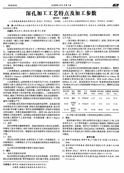
较宽敞 , 流动时 的压力损失小 , 按钻孔 的孔 径不 同 , 冷却液 的压力 般采用 4 - 1 0 k g , c m 2 。 这种排屑方式所使用的辅具较少 , 在单件生 产 中采用较普遍 。 2 ) 内排屑钻孔 : 这种排 屑方式 当钻杆孔 不大 时 , 冷却液循 环 所需压力要大 , 按孔径不同 , 压力为 1 0 — 2 5 k m 。 这种排屑方式与 外排屑 比较有下列优 点 : a . 钻杆外 圆可 比外排屑钻杆外 圆大 , 增加 了钻杆 的刚性 , 相应提 高了切削用量 o b . 钻杆外 圆包 围一层有压力 的冷却液 , 使 钻杆工作时较平稳 , 钻孔 的偏斜小 。c 切 屑 由钻杆孔
重型机械 中需加 工深孔的零件往往 重达几吨或几 十吨 , 且多 系单件生产 。由于零件 重量 大 , 机床转速不 能提 高 , 用硬质合金高 钻杆用厚壁无缝 钢管制作 。高速切 削扭矩大则用合 金钢管 , 速切削受到一定影 响。单 件生产 的零件 尺寸互部相 同 , 每次更换 外圆加工到 的配合 。 钻杆与钻杆及钻杆头之间 的连接用浅扣方 零件要更换大量 的辅具 , 因此 总的加工效率较低 。如何提高重 型 牙螺纹并带有定位台阶。根据钻孔直径和排屑方式钻杆的直径也 零件单件生产 的深孔加工 效率 以及推行 高速 切削 , 有待今后 实践 不同。 中解 决 。 1 . 3 钻头 参 考 文献 深孔钻 头的形式很 多 , 长常用有以下几种 : 1 ) 外排屑钻头 。2 ) [ 1 】齿轮 手册 编委 会. 齿轮 手 册上 T[ M I . 北京: 机械 工 业 出版社 , 内排屑钻头 。内排屑钻头又可分为高速钢 内排屑钻头和硬质合金 20 00 .
科技瓷 坛
民营科技2 0 1 5 年第7 期
深 孔加工工艺特 点及 加工 参数
简述镗床的主要功用

镗床的主要功用一、引言镗床(Boring Machine)是一种用于加工孔类工件的机床,可以用来扩大、修正、精加工孔径。
它在机械加工领域中应用广泛,主要用于加工大型工件、精密工件和特殊形状工件的孔。
本文将详细介绍镗床的主要功用,包括以下几个方面:二、修整孔径使用镗床对孔进行加工可以在保持原有孔调的情况下修整孔径。
当工件的孔径与要求的公差不符合时,使用镗床可以通过一次或多次加工,按照要求将孔径修整到满足设计要求的范围内。
这在制造精密配合件时尤为重要,可以保证零件的相互配合精度,提高装配质量。
三、提升加工精度镗床具有较高的加工精度,可以加工出精度较高的孔。
相比于普通的钻床、铣床等机床,镗床具有更好的刚性和稳定性,能够在高速切削的同时保持较高的精度。
通过适当的刀具选择和精确的切削参数控制,镗床可以加工出精度可达几十个μm甚至更高的孔。
四、加工大型工件由于镗床的刚性和稳定性较强,因此非常适用于加工大型工件。
相比于其他机床,镗床在加工大孔径和深孔时能够更好地保持工具的刚性和切削稳定性,降低振动、共振的产生。
这能够有效避免工件变形、孔偏斜等问题,使得加工结果更加稳定、准确。
五、精密配合在一些要求高精度配合的工况下,使用镗床可以实现精密配合。
通过选用合适的刀具和切削参数,镗床可以加工出尺寸精确、光洁度好的孔表面,从而实现与配合零件的良好配合。
5.1 离心体与轴承的配合离心体与轴承的配合是一种常见的精密配合工况。
通过镗床进行加工,能够使离心体、轴承的尺寸精确、圆度好,从而保证其在高速旋转时的稳定性和可靠性。
5.2 齿轮的配合齿轮也是一种常见的精密配合工况。
通过镗床对齿轮孔进行加工,可以保证齿轮与轴的配合精度,确保传动系统的准确度和可靠性。
六、节约时间和成本使用镗床加工孔比起传统的手工方法或其他机床加工要更加高效,可以大大缩短加工时间,提高生产效率。
镗床可以通过自动化操作、多刀具同时加工等方式,实现批量加工,降低劳动力成本和生产成本。
TS2163型深孔钻镗床刀具及参数介绍
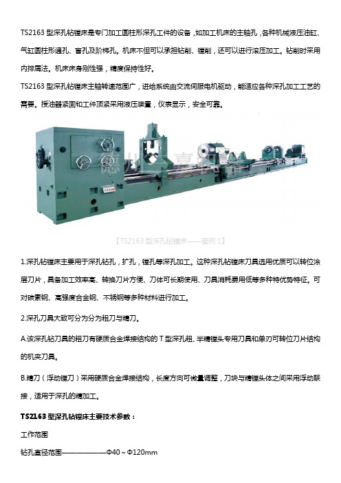
TS2163型深孔钻镗床是专门加工圆柱形深孔工件的设备,如加工机床的主轴孔,各种机械液压油缸、气缸圆柱形通孔、盲孔及阶梯孔。
机床不但可以承担钻削、镗削,还可以进行滚压加工。
钻削时采用内排屑法。
机床床身刚性强,精度保持性好。
TS2163型深孔钻镗床主轴转速范围广,进给系统由交流伺服电机驱动,能适应各种深孔加工工艺的需要。
授油器紧固和工件顶紧采用液压装置,仪表显示,安全可靠。
【TS2163型深孔钻镗床——图例1】1.深孔钻镗床主要用于深孔钻孔,扩孔,镗孔等深孔加工。
这种深孔钻镗床刀具选用优质可以转位涂层刀片,具备加工效率高、转换刀片方便、刀体可长期使用、刀具消耗费用低等多种特优势特征。
可对碳素钢、高强度合金钢、不锈钢等多种材料进行加工。
2.深孔刀具大致可分为分为粗刀与精刀。
A.该深孔钻刀具的粗刀有硬质合金焊接结构的T型深孔粗、半精镗头专用刀具和单刃可转位刀片结构的机夹刀具。
B.精刀(浮动镗刀)采用硬质合金焊接结构,长度方向可微量调整,刀块与精镗头体之间采用浮动联接,适用于深孔的精加工。
TS2163型深孔钻镗床主要技术参数:工作范围钻孔直径范围——————Φ40~Φ120mm镗孔最大直径——————Φ630mm套料直径范围——————Φ120~Φ340mm镗孔最大深度————1-16m(每一米一种规格)卡盘夹持直径范围————Φ100~Φ800mm【TS2163型深孔钻镗床——图例2】主轴部分主轴中心高————————630mm床头箱前端锥孔——————Φ100床头箱主轴前端锥孔————Φ120 1:20床头箱主轴转速范围————16~270r/min ;12级进给部分进给速度范围———————5-500mm/min;无级托板快速移动速度——————2m/min电机部分主电机功率————————45kW液压泵电机功率——————1.5kW快速移动电机功率——————5.5 kW进给电机功率————————7.5kW冷却泵电机功率————5.5kWX3+7.5kW(4组)其他部分导轨宽度——————————800mm冷却系统额定压力——————2.5MPa冷却系统流量————100、200、300、600L/min 液压系统额定工作压力——————6.3MPa授油器承受最大轴向力——————68kN授油器对工件的最大顶紧力————20 kN钻杆箱部分(选配)钻杆箱前端锥孔——————Φ100钻杆箱主轴前端锥孔————Φ120 1:20钻杆箱主轴转速范围————82~490r/min ;6级钻杆箱电机功率——————30KW【TS2163型深孔钻镗床——图例3】德州三嘉机器制造有限公司位于山东省德州市经济开发区,是集开发、设计、制造、销售普通深孔加工机床(深孔钻床、深孔钻镗床、深孔镗床),以及数控深孔加工机床(数控深孔钻床、数控深孔钻镗床、数控深孔强力珩磨机)于一体的专业厂家。
数控双头镗床技术参数

数控双头镗床技术参数
数控双头镗床是一种先进的机械设备,具备高效、精密、自动化等特点。
下面我将从技术参数的角度,向大家介绍数控双头镗床的特性和应用。
数控双头镗床的主轴转速范围广,可根据加工要求进行调节。
它可以在高速加工和精密加工之间灵活切换,满足不同工件的需求。
同时,数控双头镗床具备较大的加工行程范围,可以完成各种大小工件的加工任务。
数控双头镗床的自动化程度高,操作简单方便。
通过预设程序,只需输入加工参数,便可实现自动化加工过程,大大提高了生产效率。
而且,数控双头镗床还具备自动换刀功能,可根据不同加工工序自动选择合适的刀具,减少了人工干预的需求。
数控双头镗床具备高精度的加工能力。
其定位精度和重复定位精度都非常高,可以达到微米级别的精度要求。
这使得它在精密加工领域有着广泛的应用,如模具制造、航空航天零件加工等。
数控双头镗床还具备高刚性和稳定性。
它采用了坚固的机床结构和先进的控制系统,可以稳定地运行并完成复杂的加工任务。
这保证了加工过程中的工件精度和表面质量。
总的来说,数控双头镗床是一种功能强大、性能优越的机械设备。
它不仅可以提高生产效率,降低劳动强度,还可以保证加工质量和
精度。
随着科技的不断进步,数控双头镗床的应用领域将会更加广泛,为工业制造注入更多活力。
数控深孔钻床的特点和优势介绍

数控深孔钻床的特点和优势介绍
济南硕超数控凭着优质的产品,及时有效的售后服务,赢得了众多国内外客户的一致认可,那接下来,硕超数控小编就来为您分析一下我们的深孔钻床的产品特点和优势。
数控深孔钻,是石油、化工、制药、热电站、核电站等行业,管壳式换热器管板钻孔加工的高效设备。
数控深孔钻的最大加工直径为φ2500mm,最大钻孔深度为800mm。
1、深孔钻床属于卧式深孔钻床,铸造的床身精度稳定,上面装有纵向滑台,用来承载立柱作纵向(X向)移动;立柱上装有垂直滑台,承载主轴进给滑台等作垂直(Y向)移动;主轴进给滑台带动主轴作进给(Z向)运动。
2、数控深孔钻的两个主轴,可以同时工作,效率比单主轴机床提高了近一倍。
双主轴间距可以调节,以适应不同的孔距要求。
3、数控深孔钻可以使用BTA钻,亦可使用枪钻,这样钻小孔可用枪钻,钻大孔可用BTA钻,极大的提高了可钻削的孔径范围,可钻φ10~φ40mm的孔。
日本落地镗床大修工艺
日本落地镗床电气大修工艺前言日本落地镗床是我厂重要设备,用于加工大型工件上的内孔、沟槽和平面,原为上世纪70年代的产品,已使用了30余年,由于该设备担负的生产任务重,电气系统也已经多年未彻底大修,致使该设备近年来故障频发,严重影响生产质量和进度。
为了满足设备加工工艺和精度要求,保证生产质量,经车间班组和分厂有关部门研究决定,对其进行大修。
大修前,对机床进行全面预检,对设备进行计划大修是保证设备处于完好状态的有力措施。
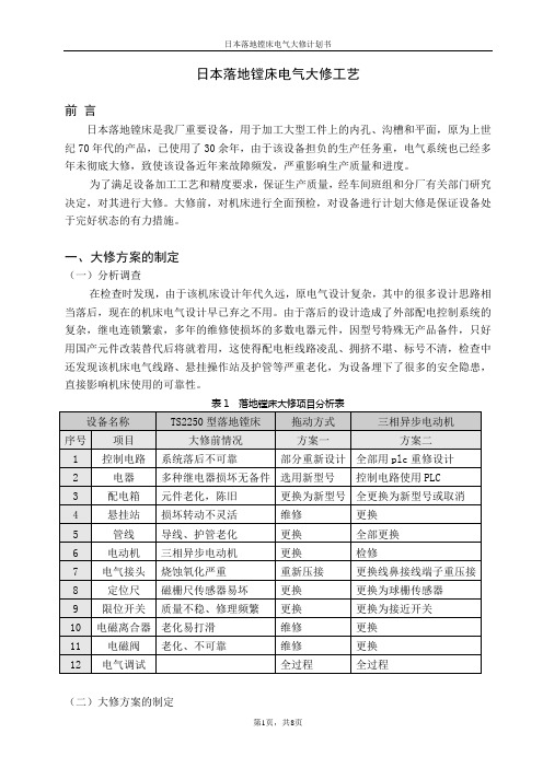
一、大修方案的制定(一)分析调查在检查时发现,由于该机床设计年代久远,原电气设计复杂,其中的很多设计思路相当落后,现在的机床电气设计早已弃之不用。
由于落后的设计造成了外部配电控制系统的复杂,继电连锁繁索,多年的维修使损坏的多数电器元件,因型号特殊无产品备件,只好用国产元件改装替代后将就着用,这使得配电柜线路凌乱、拥挤不堪、标号不清,检查中还发现该机床电气线路、悬挂操作站及护管等严重老化,为设备埋下了很多的安全隐患,直接影响机床使用的可靠性。
表1 落地镗床大修项目分析表(二)大修方案的制定车间组织相关技术人员和负责人、维修电工、操作工一起讨论大修方案,根据工作实际和工艺要求调整提出大修方案,并由分管领导签发。
考虑几个方面的可行性:1、大修设备的投产启用:因合理的设计,投产启用后机床可靠性大大提高,从而保证了质量要求,采用先进的PLC控制,将大大降低设备的维修量,以往修理浪费的时间,将被充分利用从而提高劳动生产率。
2、电器市场分析:大修采用的器件都较先进,总体比常规器件贵出数倍,但系统稳定性非常高,因此而节约的维修费用和增加的劳动生产率将会带来更高的价值。
3、大修费用:因自主完成机床设计和改造,仅此一项就为企业节约改造成本8--10万元。
在过程中通过两个方案的比较调整,合理的降低大修费用。
4、大修期限:为不影响生产进度,大修将在一个月内完成全部改造并试车投产。
5、技术力量的配备:大修工作有车间主任工程师全面负责、技术员指导编制PLC程序,电工班大修小组由技师一人、高级工两人、中级工两人组成,技术力量全面,搭配合理,完全能够胜任工作。
TS2225型深孔镗床工作原理及参数

TS2225型深孔镗床是专门加工圆柱形深孔工件的设备,如加工各种机械液压油缸、气缸圆柱形通孔、盲孔及阶梯孔。
机床可以承担镗削,还可以进行滚压加工。
机床床身刚性强,精度保持性好。
主轴转速范围广,进给系统由交流伺服电机驱动,能适应各种深孔加工工艺的需要。
授油器紧固和工件顶紧采用液压装置,仪表显示,安全可靠。
【TS2225型深孔镗床——图例1】TS2225型深孔镗床为系列产品,还可以按照客户需要提供各种变形产品。
深孔钻镗床工作原理是:在模具加工正常加工过程中,伴随着钻孔的深入,刀具所受钻削扭矩基本保持不变,电机的功率也基本保持不变。
而当刀具损坏后,则刀具所受扭矩变大,从而引起电机电流增大,通过PLC的模拟量输入模块将检测到模拟量信号转变为数字量信号,利用PLC的运算功能与设定值进行比较,来确定刀具是否损坏。
利用调速装置的模拟量输出口将检测到的电流信号转换成0~10V电压信号,输出到PLC的模拟量输入模块进行A/D模数转换,然后与设定值进行比较。
这个设定值由工艺人员根据工件材质,刀具,加工量等参数得到,通过拔段开关来选择。
当检测值大于设定值20%时,则判定扭矩过载,即刀具受损,PLC发出报警,停止加工,更换刀具, 工件深孔加工。
TS2225型深孔镗床主要技术参数工作范围镗孔直径范围——————Φ40~Φ250mm镗孔最大深度————1-16m(每一米一种规格)卡盘夹持直径范围————Φ60~Φ300mm【TS2225型深孔镗床——图例2】主轴部分主轴中心高———————350mm床头箱前端锥孔——————Φ75床头箱主轴前端锥孔————Φ85 1:20床头箱主轴转速范围————42~670r/min ;12级进给部分进给速度范围———————5-500mm/min;无级托板快速移动速度——————2m/min电机部分主电机功率————————30kW液压泵电机功率——————1.5kW快速移动电机功率——————3 kW进给电机功率————————4.7kW冷却泵电机功率———————7.5kW其他部分导轨宽度——————————650mm冷却系统额定压力——————0.36 MPa冷却系统流量————————300L/min液压系统额定工作压力——————6.3MPa授油器承受最大轴向力——————68kN授油器对工件的最大顶紧力————20 kN【TS2225型深孔镗床——图例3】镗杆箱部分(选配)镗杆箱前端锥孔——————Φ100镗杆箱主轴前端锥孔————Φ120 1:20镗杆箱主轴转速范围————82~490r/min ;6级镗杆箱电机功率——————30KW【TS2225型深孔镗床——图例4】德州三嘉机器制造有限公司位于山东省德州市经济开发区,是集开发、设计、制造、销售普通深孔加工机床(深孔钻床、深孔钻镗床、深孔镗床),以及数控深孔加工机床(数控深孔钻床、数控深孔钻镗床、数控深孔强力珩磨机)于一体的专业厂家。
镗床名词解释

镗床名词解释镗床是一种用于加工内孔的金属切削机床,具有高精度、高效率、高刚性和多功能的特点。
它是制造机器和精密零件的不可或缺的设备之一,广泛应用于航空航天、轨道交通、汽车、电子、仪器仪表、机械制造等各个领域。
本文将从镗床的工作原理、结构组成、分类及应用领域等方面进行详细解释。
一、镗床的工作原理镗床是利用回转刀具在工件内径上切削金属,将内表面加工到规定尺寸和表面粗糙度的高精度金属切削机床。
它通过刀具的旋转和进给以及工件的旋转,使切削刃进入工件内孔进行金属切削加工。
在加工过程中,工件的旋转是使得加工精度和表面质量达到设计要求的重要因素之一。
镗床可分为刀具转动式和工件转动式两种类型。
刀具转动式镗床通常用于加工较小的孔径,而工件转动式镗床则用于加工较大的孔径。
二、镗床的结构组成镗床的主体部分包括床身、工作台、立柱、横梁、主轴箱、进给箱、尾架等组成部分。
具体结构可分为以下几个方面:1.床身:它是镗床的支撑部件,是整个机床的重要组成部分。
床身通常使用铸铁或钢板烤漆,以保证机床的高强度和高刚性。
2.工作台:它用于夹持和支承工件,在工作过程中可以通过手柄或电动机调整工件高度和倾角,以实现不同形状和尺寸的工件加工。
3.立柱和横梁:它们是机床的主要支撑部件,通过精密的滚珠导轨和螺杆传动机构实现主轴箱的升降和进给箱的移动。
4.主轴箱:它是镗床的核心部件,由电机、主轴、前后轴承、变速箱及相应的控制系统组成,主要用于切削刀具的转动和进给。
5.进给箱:它通过螺杆传动、齿轮驱动和摆线针轮机构,实现镗刀在工件内径方向的进给、调速和倒切等运动。
6.尾架:它用于支撑工件的一端,在加工长孔和大孔时起到稳定工件和保持加工精度的作用。
三、镗床的分类1.按结构分类:可分为卧式镗床和立式镗床两种类型。
卧式镗床床身水平铺设,工作台固定在床身上,其适用于加工较大的孔径。
而立式镗床床身竖直设置,工作台水平行动,适用于加工较小的孔径。
2.按工作方式分类:可分为手动镗床和数控镗床两种类型。
数控双头镗床技术参数
数控双头镗床技术参数数控双头镗床是一种高效、精确的金属加工设备,具有双头同时加工的特点。
它能够在一次装夹中同时进行两个工件的镗孔加工,大大提高了生产效率和加工精度。
下面将从不同角度介绍数控双头镗床的技术参数。
一、主要技术参数1. 镗孔直径范围:数控双头镗床可根据不同的加工需求,灵活调整镗孔直径范围。
通常,镗孔直径范围为10mm至200mm,可以满足大部分工件的加工要求。
2. 加工精度:作为一种高精度加工设备,数控双头镗床的加工精度非常重要。
通常,其加工精度可达到0.01mm,能够满足大部分工件的精度要求。
3. 加工速度:数控双头镗床具备高速加工的特点,可以根据不同工件的加工要求,调整加工速度。
通常,加工速度可达到2000rpm,大大提高了生产效率。
4. 加工深度:数控双头镗床的加工深度可以根据工件的需求进行调整。
通常,加工深度可达到100mm,可以满足大部分工件的加工要求。
二、创新技术参数1. 自动化程度:数控双头镗床采用先进的自动化控制系统,可以实现自动化的加工过程,大大降低了人力成本和人为误差。
2. 进给速度:数控双头镗床的进给速度可根据工件的材质和加工要求进行调整。
通常,进给速度可达到1000mm/min,确保了加工效率和加工质量。
3. 刀具寿命:数控双头镗床采用高硬度的刀具材料,具有较长的使用寿命。
通常,刀具寿命可达到2000小时以上,大大降低了刀具更换频率和加工成本。
4. 运行稳定性:数控双头镗床采用先进的结构设计和稳定的控制系统,确保了设备的运行稳定性。
在长时间运行中,几乎没有振动和噪音,保证了加工质量和操作安全。
总结起来,数控双头镗床是一种高效、精确的金属加工设备,具有广泛的应用领域。
它的主要技术参数包括镗孔直径范围、加工精度、加工速度和加工深度等。
同时,它还具备自动化程度高、进给速度快、刀具寿命长和运行稳定性好等创新技术参数。
通过合理调整这些技术参数,数控双头镗床能够满足不同工件的加工需求,提高加工效率和加工质量。
镗床有哪些基础知识内容介绍
镗床有哪些基础知识内容介绍镗床主要用于加工高精度孔或一次定位完成多个孔的精加工,不过对于外行人来说这个词可能没有听说过。
以下是由店铺整理关于镗床知识的内容,希望大家喜欢!镗床的概述镗床分为卧式镗床、落地镗铣床、金刚镗床和坐标镗床等类型(见彩图)。
①卧式镗床:应用最多、性能最广的一种镗床,适用于单件小批生产和修理车间。
②落地镗床和落地镗铣床:特点是工件固定在落地平台上,适宜于加工尺寸和重量较大的工件,用于重型机械制造厂。
③金刚镗床:使用金刚石或硬质合金刀具,以很小的进给量和很高的切削速度镗削精度较高、表面粗糙度较小的孔,主要用于大批量生产中。
④坐标镗床:具有精密的坐标定位装置,适于加工形状、尺寸和孔距精度要求都很高的孔,还可用以进行划线、坐标测量和刻度等工作,用于工具车间和中小批量生产中。
其他类型的镗床还有立式转塔镗铣床、深孔镗床和汽车、拖拉机修理用镗床等。
镗床的发展史由于制造武器的需要,在15世纪就已经出现了水力驱动的炮筒镗床。
1769年J.瓦特取得实用蒸汽机专利后,汽缸的加工精度就成了蒸汽机的关键问题。
1774年英国人J.威尔金森(又译约翰·威尔金森)发明炮筒镗床,次年用于为瓦特蒸汽机加工汽缸体。
1776年他又制造了一台较为精确的汽缸镗床。
1880年前后,在德国开始生产带前后立柱和工作台的卧式镗床。
为适应特大、特重工件的加工,20世纪30年代发展了落地镗床。
随着铣削工作量的增加,50年代出现了落地镗铣床。
20世纪初,由于钟表仪器制造业的发展,需要加工孔距误差较小的设备,在瑞士出现了坐标镗床。
为了提高镗床的定位精度,已广泛采用光学读数头或数字显示装置。
有些镗床还采用数字控制系统实现坐标定位和加工过程自动化。
镗床的结构特点1、以箱体零件同轴孔系为代表的长孔镗削,是金属切削加工中最重要的内容之一。
尽管仍有采用镗模、导套、台式铣镗床后立柱支承长镗杆或人工找正工件回转180°等方法实施长孔镗削的实例,但近些年来,一方面由于数控铣镗床和加工中心大量使用,使各类卧式铣镗床的坐标定位精度和工作台回转分度精度有了较大提高,长孔镗削逐渐被高效的工作台回转180°自定位的调头镗孔另一方面形床身布局之普通或数控刨台式铣镗床的大量生产和应用,从机床结构上使工作台回转180°自定位的调头镗孔,几乎成为在该种机床上镗削长孔的唯一方法。
中捷数控镗床说明书

中捷数控镗床说明书一、简介二、主要特点1.高精度:中捷数控镗床采用精密的传动装置和控制系统,能够实现高精度加工,保证产品质量。
2.高效率:中捷数控镗床具有高速镗削功能,能够提高生产效率,减少加工时间。
3.灵活性:中捷数控镗床能够根据不同的加工需求进行灵活调整,满足不同产品的加工要求。
4.操作简便:中捷数控镗床采用人机界面操作系统,操作简单方便,操作人员上手快。
三、技术参数1. 最大镗削直径:300mm2. 最大镗削长度:500mm3. 镗削精度:0.01mm4. 主轴转速范围:200-3000rpm5. 进给速度范围:1-1000mm/min6.主轴功率:5.5kW7.控制系统:数控控制系统四、操作步骤1.打开电源开关,启动设备。
2.设置加工参数,包括镗削直径、长度、加工速度等。
3.将工件固定在工作台上,调整工件位置和角度。
4.启动主轴和进给系统,开始进行加工。
5.监控加工过程,保证加工质量。
6.加工完成后,关闭设备,清理工作区域。
五、注意事项1.操作人员应熟悉设备的操作流程和安全规定,严禁未经许可进行操作。
2.在操作过程中,应保持设备和工作区域的清洁,定期进行检查和维护。
3.加工过程中,应保持设备稳定运行,避免出现异常状况。
4.加工润滑剂应适量使用,避免过多或过少对加工质量的影响。
5.使用完毕后,及时关闭设备和电源开关,确保安全。
六、维护保养1.定期对设备进行检查和维护,及时处理故障和异常情况。
2.清洁设备表面和工作区域的杂物和灰尘,保持设备干净整洁。
3.定期对设备的传动装置进行润滑,确保设备的正常运行。
4.注意设备的保养和维修,延长设备的使用寿命。
七、故障排除1.设备不能启动:检查电源是否接通,检查控制系统是否正常。
2.镗削直径不准确:调整设备的加工参数,检查刀具的磨损情况。
3.镗削长度不准确:检查进给系统的调整情况,调整进给速度。
4.切削过程出现异常声音:检查刀具和主轴的装配情况,修复或更换损坏部件。
TS2135型深孔钻镗床特点、技术参数
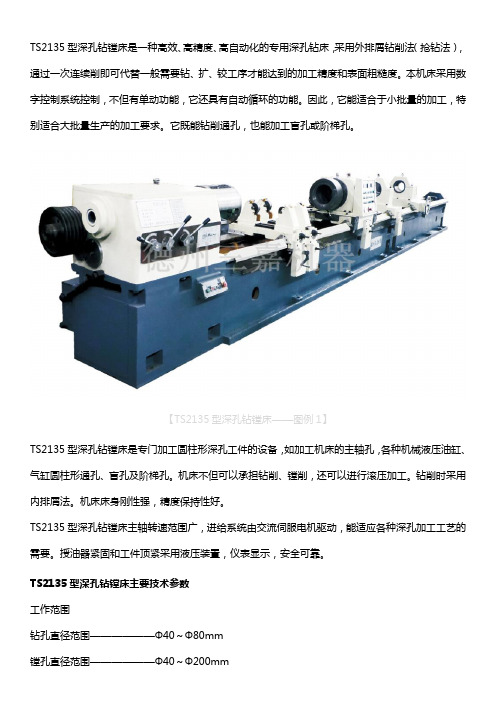
TS2135型深孔钻镗床是一种高效、高精度、高自动化的专用深孔钻床,采用外排屑钻削法(抢钻法),通过一次连续削即可代替一般需要钻、扩、铰工序才能达到的加工精度和表面粗糙度。
本机床采用数字控制系统控制,不但有单动功能,它还具有自动循环的功能。
因此,它能适合于小批量的加工,特别适合大批量生产的加工要求。
它既能钻削通孔,也能加工盲孔或阶梯孔。
【TS2135型深孔钻镗床——图例1】TS2135型深孔钻镗床是专门加工圆柱形深孔工件的设备,如加工机床的主轴孔,各种机械液压油缸、气缸圆柱形通孔、盲孔及阶梯孔。
机床不但可以承担钻削、镗削,还可以进行滚压加工。
钻削时采用内排屑法。
机床床身刚性强,精度保持性好。
TS2135型深孔钻镗床主轴转速范围广,进给系统由交流伺服电机驱动,能适应各种深孔加工工艺的需要。
授油器紧固和工件顶紧采用液压装置,仪表显示,安全可靠。
TS2135型深孔钻镗床主要技术参数工作范围钻孔直径范围——————Φ40~Φ80mm镗孔直径范围——————Φ40~Φ200mm镗孔最大深度————1-16m(每一米一种规格)卡盘夹持直径范围————Φ60~Φ300mm进给部分进给速度范围———————5-300mm/min;无级托板快速移动速度——————2m/min【TS2135型深孔钻镗床——图例2】电机部分主电机功率————————30kW液压泵电机功率——————1.5kW快速移动电机功率——————3 kW进给电机功率————————4.7kW冷却泵电机功率———————5.5kWX4主轴部分主轴中心高———————350mm床头箱前端锥孔——————Φ75床头箱主轴前端锥孔————Φ85 1:20床头箱主轴转速范围————42~670r/min ;12级其他部分导轨宽度——————————650mm冷却系统额定压力——————2.5MPa冷却系统流量————100、200、300、400L/min液压系统额定工作压力——————6.3MPa授油器承受最大轴向力——————68kN授油器对工件的最大顶紧力————20 kN钻杆箱部分(选配)钻杆箱前端锥孔——————Φ100钻杆箱主轴前端锥孔————Φ120 1:20钻杆箱主轴转速范围————82~490r/min ;6级钻杆箱电机功率——————30KW德州三嘉机器制造有限公司拥有先进的深孔加工技术,拥有一支精益求精、不懈创新的科研团队。
镗床的类型和用途

镗床的类型和用途
镗床主要是用来加工高精度的孔或一次性完成多个孔的精加工,另外还可进行与孔精加工相关的其它表面加工。
用各种刀具和附件也可以进行钻削、铣削、切割,其加工精度和表面质量都比钻床高。
镗是加工大型箱体零件的主要设备。
螺旋及加工外圆、端面等。
镗削加工的主要形式是用镗刀在已铸孔或已粗钻的工件上加工孔,此外,大多数镗床还可进行铣、钻、扩、铰等加工。
镗床分为卧式镗床、落地镗铣床、金刚镗床和坐标镗床等类型:
1、卧式镗床:应用广泛,性能较好的一种镗床,适用于单件小批量生产车间和修理厂。
2、地面镗床和地面铣床:特点工件是固定在地面工作台上,适合重型机械制造厂加工尺寸较大、重量较大的工件。
3、金刚镗床:采用钻石或硬质合金刀具,进给极小,进刀速度快,镗削精度高,表面粗糙度小,主要用于大批量生产。
4、坐标镗床:具有精密的坐标定位装置,适用于对形状、尺寸、孔距等精度要求较高的孔的加工,也可用于划线、坐标测量和刻度,用于工具室和中小批量生产。
其它类型的镗床有立式转塔镗铣床,深孔镗床,汽车、拖拉机修理厂用镗床等。
一种以镗刀对已加工好的工件孔进行镗削的机床。
一般转动以镗刀转动为主,进给运动是镗刀或工件的转动。
该装置主要用于高精度孔的加工,或一次性完成多个孔的精加工,并可进行与孔精加工相关的其它表面加工。
用各种刀具和附件也能进行钻削、铣削,切削时的加工精度和表面质量都比钻床高。
镗是加工大型箱体零件的主要设备。
螺旋及加工外圆、端面等。
深孔机床简介

深孔机床简介【德州三嘉机器】深孔机床按结构形式分为立式深孔机床和卧式深孔机床,立式深孔机床主要为立式深孔钻床和立式深孔珩磨机。
卧式主要有深孔钻镗床,深孔镗床、深孔钻床、深孔枪钻、深孔珩磨机。
钻孔时,枪钻采用枪钻内孔给油,枪钻V型槽排出;BTA钻孔时,采用授油器给油,钻杆内孔排出。
深孔镗加工时,根据工件的长短选用两种加工工件艺:短工件采用授油器授油并液压顶紧;长工件采用由镗杆尾部授油,四爪卡盘夹紧。
#详情查看#【德州三嘉机器:深孔机床】什么叫深孔?深孔是指孔深与孔径比L/d≥6的孔,深孔加工是机械加工中的一道难题,尤其是大深径比的深孔加工,难点在于刀具细长,刚性差、强度低,易引起刀具偏斜,且散热困难,排屑不易,经常产生直径变大、出现锥形或孔偏斜等现象,从而达不到质量要求。
航空发动机某喷嘴类零件,孔径为Ф6mm,孔深为105mm,深径比达17:1。
超大的深径比更增加了此零件的加工难度,为了加工出合格孔,需制定合理的加工方案,选择合适的加工设备和刀具。
笔者经过试件的试切加工,选择合适的加工参数,最终确定了合理的加工方法。
深孔机床零件简介某喷嘴类零件,总长为105mm,杆部内孔为φ6+0.12mm,壁厚为2mm,表面粗糙度为Ra3.2μm,深径比为17:1,属于深孔加工的零件,其材料为难加工的GH4169。
这类高温合金孔加工相对于一般钢材切削加工,刀具寿命要低50%以上,且加工效率低,成本高。
高温合金孔加工主要难点是:①切削力大,消耗机床功率大;②孔加工是半封闭的切削,产生的高切削热和切屑难以及时排出,远离刀尖,刀具磨损更为剧烈;③用普通的钻削方法难以保证高温合金孔的精度要求。
④高温合金孔加工中,刀具磨损比加工普通钢材快得多,且需要切削性能更好的刀具材料。
为了解决以上加工难点,加工此深孔时,必须选择合适的加工设备和刀具,保证零件的加工精度。
ZSK21系列深孔钻床(枪钻机床)该机床是用于钻削圆柱形棒料的深孔加工设备,他是一种高效、高精度、高自动化的采用外排屑法(枪钻法)钻削小孔的机床。
深孔钻镗床的优势及保养方案

深孔钻镗床行业越来越多的走进我们日常的生活中,在不少机械加工中我们都可以看到钻床的应用,几乎凡事需要用到零件的部门都需要钻床的应用诸如安全阀门、汽车转向器、发动机、制动器、校油泵以及家用的很多电子商品像是太阳能、电视机、冰箱等等在生产的时候都应用可调多轴钻床,今天我们德州三嘉机器去就给大家说一下关于深孔钻镗床的优势和保养方案。
深孔钻镗床是加工圆柱形深孔钻零件的专用机床。
可以镗削通孔、阶梯孔和盲孔,也可进行光整滚压加工。
对于短工件(1-4m)采用双锥盘顶紧方式,由授油器授油。
在镗削方法上采用推镗。
在排屑方式上采用向前排屑,适用于大批量生产,也可用于单件小批生产。
1、机床由床身。
床头箱、授油器、拖板、拖板进给系统、中心架、拖架、镗杆支架、镗杆箱、冷却系统、电气系统、液压系统、排屑装置等主要部件组成。
2、机床床身、拖板、箱体、授油器体、支架体等零部件均采用高强度铸铁、树脂砂造型,保证机床刚性好、强度高、精度保持性好。
床身采用国际先进额中频淬火,淬火深度3—5mm,HRC48-52,耐磨性较高。
3、由授油器授油,授油器装置与机床主轴同心度高,更换导向套方便。
镗削方式为推镗,排屑方式为前排屑。
工件旋转,工件俩端外圆倒角大于5×30°,为工件夹紧定位用。
镗杆旋转并由拖板带动实现纵向进给。
深孔钻镗床机床的保养内容:①每日工作完后,擦拭机台及清理加工槽,使机台及加工保持干净;②清洁电箱时,务必切断总电源,以防触电;③清洁机台不能用甲苯或乙醚等酸性化学试剂清洁,可用酒精或中性清洁剂擦拭,不得使用清理,以免铁屑飞入螺杆及导轨里,建议用胶刮片清理;④每月一次例行全面检查清洁机台电箱;⑤长时间不使用机器时,加工面及轨道部位上油防锈;⑥机床要保持干净及防锈工作,避免机床周边地面有油渍。
深孔镗头简介

The ECOROLL combined counter-boring, skive- and burnishing tool type RIOF meets the relevant health and safety standards. Make sure to read these operating instruc-tions carefully before operating the device. The manual contains important notes for the operation and maintenance. Protect yourself and prevent damage from the tools.ECOROLL AG Werkzeugtechnik P.O. 31 42 D-29231 CelleHans-Heinrich-Warnke-Straße 8 D-29227 CelleTelephone: + 49 (0) 5141-9865-0 Telefax: + 49 (0) 5141-881440 Web: www.ecoroll.de E-Mail: mail@ecoroll.deOperating Instructions No. 270707/2 Skive-and Roller Burnishing Tool RIOFOperating instructions no. 270707/1ERIOF Skive- and Roller Burnishing ToolTable of contents1Application 41.1Tool types and diameter ranges 41.2Tool features 41.3Intended purpose 5 2Safety instructions 5 3Tool Design 63.1Skiving head 73.1.1 Cutting inserts and support inserts 73.2Roller burnishing head 8 4Function 94.1Coolant-lubricant and chip removal 10 5Preparation of Machine and tubes 105.1Tubes 115.2Guide bushings 115.3Rotation direction 115.4Mounting the tool 125.5Setting the machine traverse path 12 6Tool setting 136.1Setting the roller burnishing head 136.1.1 Setting the diameter 136.1.2 Activating the roller burnishing head 146.1.3Deactivating the roller burnishing head 156.1.4 Measuring the roller burnishing head diameter 156.2Adjusting the skiving knives 166.3Measuring the skiving knives 176.3.1 Knife version Q 186.3.2 Knife version M 186.3.3 Measuring procedure 196.4 Guide pad 216.5 Support pads 22 7Working with the RIOF Tool 237.1Working parameters 237.2Start of work 247.2.1 Checking the tool’s functions 247.2.2 Checking the diameter by test cut 247.3Work cycle 258Troubleshooting 259Transport 2610Disposal 2611Maintenance, repair and re-setting 2711.1 Regular maintenance 2711.2 Replacing the rollers, the cage and the internal cone 2711.2.1 Disassembly 2811.2.2 Assembly 2911.3 Replacing the actuating cone 3011.3.1 Dissasembly 3011.3.2 Assembly actuating cone 3111.4Replacing the skiving knives 3111.4.1 Disassembly 3111.4.2 Assembly 3112Converting the skiving knives 3212.1Changing off-set “y” or version Q to M 3212.2Assembling the version Q skiving knives 3312.3Adjusting the cutting and support inserts (version Q) 3412.4Turning or replacing the cutting inserts 3413Converting into triple tool RIOA 35Spare parts 36Drawing No. 146930 371. Application1.1 Tool types and diameter rangesThe combined skive-burnishing tool is specially designed for the internal machining of cold-drawn cylinder tubes (HPZ or DOM) up to 4 m long. The tools can be converted into triple tools RIOA for counter-boring, skiving and burnishing hot rolled tubes see Chapter 13.Both processes are completed simultaneously in one pass. The tools operate under pressure and are are retracted pressure-less. To ensure optimum results we recom-mend counter rotation of tool and work piece. The patented OMEGA skiving head will reduce or eliminate rippling and errors in the circular shape of the pipes. It cuts the tube’s internal surface to the exact form and size required, while the roller head bur-nishes it. This simultaneous skiving and burnishing in one pass results in short proc-essing times.Tool type and series Diameter range (mm)RIOF 47.1, RIOF 47.2 ≥ 100 < 140RIOF 57.1, RIOF 57.2 ≥ 140 < 205RIOF 67.1 ≥ 205 < 305RIOF 67.2 ≥ 305 < 4551.2 Tool features•Skive head with 3 knives for diameter range 100 - 455 mm•Skive head with 3 plastic guide pads for optimum guidance•Central adjustment of the skive diameter by an Allen wrench•Quick coupling between skive head and tool body to allow fast exchange of rollers, inner cones or cage•Mechanic burnishing head adjustment•Plastic supports on the back end ready for use as delivered (no machining required after assembly)1.3 Intended purposeThe ECOROLL RIOf skiving and burnishing tool is intended to skive and burnish hy-draulic cylinders and cylinder tubes from cold drawn tubes in one pass. Any other use is not intended. The manufacturer is not liable for any damage caused by any other use. The user bears the risks alone.ATTENTION: The operators assigned to work Array with the tool must have read the operating in-structions, especially the chapter "Safety instruc-tions" before beginning to work with the unit.2 Safety instructionsThe ECOROLL RIOF combined counter-boring, skive and burnishing tool meets the relevant health and safety standards. However, the use of technical devices can al-ways be dangerous. Therefore, obey the indicated safety advices for your own protec-tion. The safety advices given below indicate how you can prevent danger by right be-haviour.•Never wear gloves when working with a rotating tool or Array workpiece. Danger of pull in!•Make sure to suck the coolant-lubricant fumes occurring atthe tool thoroughly off•Do not inhale the coolant-lubricant fumes and do not allowskin contact with the KSS fumes•Adhere to the regulations of the employer's liability insurance association.•Before operating the tool, check to make sure that it is in proper working condition.•Adhere strictly to the specified application parameters.•Obey all regulations concerning the work with machine tools with rotating com-ponents or rotating workpieces.•Do not touch the tool while it is removed without tripped out of the pressurehead or while it is pulled back or rotating without beeing covered byte tube.•Under the conditions given above, do not allow the tool to rotate faster than 10RPM.3 Tool DesignThe tool body (70) is equipped with support pads (120) to stabilize the tool. In the stan-dard tool version, the tool body connects the tool to the boring bar with a BTA -thread. Other interfaces, e.g. flange connections are avaialble on request.The tool operates hydraulically. Two cylinders are integrated into the tool: one controls the skiving head and one controls the roller burnishing head. The male conector Fig. 1 enables the RIOF tool to automatically connect with the machine tool’s hydraulic sys-tem. It supplies hydraulic oil to the piston (40, Fig 1) and the annular piston (90). The thread pin (30) locks the BTA-thread.When the piston (40) is hydraulically activated, the connecting rod (350), the ball head (470) and the actuating cone (460) move to the left (Fig. 1, Direction L). This extends the skiving knives (370). Simultaneously, the tension rod (160) moves to the left tight-ening the spring (180).Fig. 1L3703.1 Skiving headThe skiving head (360) is equipped with guide pads (10) and the skiving knives (370). The knives are radially floating. During the machining process, the guide pads (10) direct the skiving head (360) accurately through the tube. Skiving knives (370) are sup-ported by the floating actuating cone (460, Fig. 1). The latter builts the knive adjusting device together with flange (380) and spring (390). The knives are activated by hydrau-lic pressure at piston (40, Fig. 1)Fig. 2.13.1.1 Cutting inserts and support insertsSkiving knives can be used in version M (for most applications) and inversion Q for clinders with cross holes. Each Version M skiving knife contains two cutting inserts (410). The left one is the pre-cutter, the right one is the final cutter. The cutting edge of the latter is placed higher than the pre-cutter. This off-set is variable from 0,2 to 0,6 mm depending on the allowance (stock removal of the materialand. For more detail see Chapter 12.1. Each version Q skiving knife contains one cutting insert (410) and one support insert (410.1).360 10 370380390Fig. 2.2Fig. 3 Skiving knives version M (left) and version Q (right)The tandem cutter arrangement of version M and the support inserts of version Q im-prove the workpiece’s cylindrical form by:• Centring the knife in the guide bush when the process begins. •Limiting the float of the knife, reducing the ripple effect.Fig. 43.2 Roller burnishing headThe cage (290) guides the rollers (300) that are supported by the cone (60). The bur-nishing head in activated by hydraulic pressure along with the skiving knives. (see also section 7.3).RWhen the control pressure is applied, the annular piston (90) moves in direction R (Fig. 4) along with the bearing bushing (260) – depending on the version – the spacer (290.10) and the cage with the rollers (300). The rollers (300) move up the cone’s (60) incline, thus increasing the roller head diameter. This is the tool’s operational setting. The nut (210) is used to adjust the roller head diameter. With one setting, the roller burnishing head can process bores up to tolerance IT8 can without further adjustment.4 FunctionFigure 5 demonstrates the tool in its work setting. The tool is normally connected to the boring bar by means of a BTA -thread or any typical boring bar connection. Skiving knives and roller head are activated with hydraulic pressure.We strongly recommend to work with counter-rortation of workpiece and tool when bor-ing, skiving and roller burnishing.Fig. 5: Tool operationAll ECOROLL combined skive-burnishing tools operate exclusively in the feed direc-tion. Cutting and burnishing take place simultaneously. At the end of the process, con-trol pressure in released to collapse the tool. In this mode, the tools can be quickly re-tracted while still rotating, as long as there is an adequate supply of coolant-lubricant inthe preswsure head..BTA-thread Boring barChips4.1 Coolant-lubricant and chip removalThe coolant -lubricant supplies lubrication for the roller head, guide pad, and cutting insert and ensures that the metal chips are expelled in feeding direction. The required amount of coolant -lubricant (oil or emulsion) can be determined accor ding to the fol-lowing formula:Required amount of coolant-lubricant: V = f x DD = working diameter; f = factor V = 2.5 x D (with oil)V = 4 x D (with coolant-lubricant)Example calculation: D = 120 mmV = 2.5 x 120 = 300 l/min (with oil)V = 4 x 120 = 480 l/min (with coolant-lubricant)To ensure a trouble-free operation, make sure the coolant passage way in the machine is free of obstructions that metal chips may encounter as they are expelled from the cylinder. Step-like formations or narrowings or bends in the cylinder can cause a chip jam, which can lead to serious damage of the tool.ATTENTION: An adequate supply of coolant-lubricant is required for good chip removal andtrouble-free operation.5 Preparation of machine and tubes5.1 TubesOptimal results and wear part life can only be achived, if the tube is centred referring to the internal diameter. Preconditions are:•The cone at the pressure head is running true within max 0,05 mm.•The chamfers at the tube end run true to the internal diameter according to Fig. 5a.•Faces must be perpendicular.•I.D. and O.D. must be deburred using suitable hand power tool with cham-fers 1 x 45°.Fehler!Fig. 5a5.2 Guide bushingsEach cylinder diameter to be machined requires a cylinder-specific guide bushing made of tempered steel. Entry-sided install the guide bushing in the coolant supply system. It centres the skive head and roller head when boring. Adhere to the following: •Use a guide bushing with I.D. = nominal diameter, tolerance G7.•The bushing must be centred in the pressure head.•After the centring flanges are installed, the centring of the conical faces must within max. run true be 0.05 mm.•No guide bushing is required for the exit side. Should one be run by some rea-son, diameter, its diameter must be 5 over nominal size5.3 Rotation directionIt is recommended to rotate only the ECOROLL skive and burnishing tool. Counter-rotation is not necessary, but may be applied for some other reason. In that case, the ratio should be 60% to 40% of the total rotation speed for the tool and the tube respec-tively.5.4 Mounting the tool1. Clean the BTA or other connecting threads in the tool and on the boring bar.2. Make sure to lubricate the bore thread with a cooper based grease (e.g. KlüberWolfracoat C) to facilitate later removal.3. Align the tool and affix it to the boring bar with the ECOROLL wrench delivered withthe tool (Fig. 7). (See following NOTE).NOTE: Connecting the tool to the boring bar’s Array BTA -thread automatically connects to the tooloperaton system. No additional mounting is re-quired.Fig. 7.ECOROLL wrench5.5 Setting the machine traverse path• Starting position: Tool with flange is completely retracted in the guide bushing. •End of travel: tool emerged from the workpiece that approx. 2/3 of the roller length remain in the workpiece. The rollers should never completely leave the work-piece.6 Tool setting6.1 Setting the roller burnishing headWith one setting, the roller burnishing head can process bores up to tolerance IT8 can without further adjustment.6.1.1 Setting the diameterNOTE: This section refers to Fig. 6.The roller head is to be set larger than the skived diameter.•The criteria for roler head setting is the surface quality.•Increase of roller head diameter will decrease the roughness.•Decrease of roller head diameter will increase the roughnessThe nut (210) is used to set the diameter of the roller burnishing head. The nut (210) can be adjusted as follows:1. Loosen the set screw (230).2. To increase diameter size, turn the nut (210) to the right (clockwise in direction R).3. To decrease diameter size, turn the nut (210) to the left (counter-clockwise of ver-sion R).4. Retighten the set screw (230).5. Measure the roller burnishing head diameter as described in section6.1.4.L R Fig. 6:Setting the diameter6.1.2 Activating the roller burnishing headWhen the control pressure is released, the roller burnishing head is idle (rollers remain within the head). When the controlling pressure is applied, the annular piston (90) moves in direction R (Fig. 15) along with the bearing bushing (260) – if there is one – the spacer and the rollers (300). The rollers (300) move up the cone’s (60) incline, thus increasing the roller head diameter. The nut (23), which acts as a stopper, is used to adjust the roller head diameter. The activation pressure is to be set in a range betweenmin. and max. bars.not change the burnishing effect. Pressure must behigh enough to fully open the tool!6.1.3 Deactivating the roller burnishing headWhen the annular piston (90) moves in direction L (Fig. 15), the rollers (300) move down the cone’s (60) incline and the roller head diameter decreases such that the roll-ers are no longer under pressure. The tool can be retracted in this state.6.1.4 Measuring the roller burnishing head diameterStandard versions of the tool have roller burnishing heads with an even number of roll-ers. The rollers are always arranged such that each roller in a pair is directly opposite (180° from) the other. For the measurement activate the tool according to chapter. 6.2.2.The measurement should be taken with a micrometer gauge over the highest points on the rollers. The measuring bolt must be guided gently over the roller to find this point.ATTENTION: The diameter can only be measured over the rollers if the RETRAC system is activated. For this reason, the measurement should be made with the tool mounted in the machine tool.To measure the diameter when the tool is not in mounted in the machine tool, an additional hydraulic pressure unit is required.ECOROLL recommends using a roller burnishing head diameter that is 0.05 – 0.2 mm larger than the nominal diameter (oversize), depending on the workpiece diameter and wall thickness.After processing the first tubes and evaluating the surface finish, the roller positioning can be adjusted accordingly.Record the values for each workpiece so that they can be reused for processing the next lot.ATTENTION: Keep the difference between the di-ameter size and the workpiece diameter as low as possible for obtaining the desired surface finish! A roller burnishing diameter that is too large will reduce the service life of the rollers and the in-ternal cone.6.2 Adjusting the skivingknivesSetting of the skiving diameter infleuces the final I.D. of the cylinder:• Increase of skiving diameter will in-crease • Decrease of skiving diameter willdecrease the final diameter The skiving knives (Fig. 16, 370) can be adjusted while still mounted in the skiv-ing head.First, insert the Allen wrench (Fig. 16) through the flange (Fig. 17, 380) into the hexagon socket of the actuating one (Fig. 17, 460).Fig. 16Measusuring the knives ∅ isonly necessary before the first use of the tool for a new lot.It is recom-mended to set the knives to +0,01 tother corrections are recommended after the actual ∅Just turn the Allen wrench according to the desired ∅-change.Fig. 17wrench380370Turning the wrench to the left (counter-clockwise) will set the knives (Fig 18, 370) to a smaller diameter and turning to the right (clock-wise) will set them to a lar-ger diameter.The arrow with the + sign next to it engraved in the flange (380) indicates the turning direction for increas-ing the diameter. Each scale line engraved on the edge of the flange indicates an ad-justment of 0.005 mm. The scales are engraved on the circumference of the flange (380).ATTENTION: After adjusting the skiving knives to a smaller diameter, press the knives by hand in the ra-dial direction indicated by the arrows pointing in di-rection C (see Fig. 20).6.3 Measuring the skiving knivesThe skiving knive diameter can be measured while still mounted in the skiving head and can be set using the adjusting screw in the cone (Fig. 17, 460). Because the knives do not require disassembly for these procedures, the overall processing time is shorter. This reduces set times.Scales380370CFig. 18Arrow:Increase diameter by turning in + direc-tion, decrease in - directionATTENTION: The diameter over the skiving knives can only be measured if the control pressure is activated. For this reason, the measurement should be made with the tool mounted in the machine tool.To measure the diameter when the tool is not in mounted in the machine tool, an additional hydraulic pressure unit is required.When measuring the cutting diameter, always measure over the finish cutter.6.3.1 Knife version QMeasure over the front cutting inserts (b). The Q versions are normally not used with RIOF.Fig. 196.3.2 Knife version MMeasure over the rear cutting inserts (g).Fig. 206.3.3 Measuring procedureThese tools are delivered with three knives. The measuring pin (Fig. 22) delivered with the tool is required to measure skiving heads with three knives. It is delivered with the tool.The holes that accommodate the measuring pin for measuring this tool’s skiving head are located exactly opposite one of the knives under the guide pad. A large numeral “1” is engraved next to this guide pad (see Fig. 21). Measure the cutting diameter as follows:1.Disassemble the one guide pad (10) next to the engraved “1“.Fig. 212. Insert the measuring pin and use the indexing pin to position it. Some versions arenot delivered with an index pin, the measuring pin, however, cannot be insertedwrongly.Fig. 223. Place the micrometer gauge measuring bolt against the highest point of the cuttinginsert (Fig 25).Index pinFig. 234. Place the other micrometer gauge bolt against the highest point of the measuringpin.Fig. 24 5. Adjust the micrometer gauge measuring bolt until the ratchet disengages.NOTE: To find the exact measuring point, move the micrometer gauge bolt slowly over the measuring pin until the highest point is located.6.Read the diameter.Fig. 256.4 Guide PadsRIOF 4 tools are equipped with three skiving knives and three guide pads. The guide pad diameter can only be determined using an ancillary measurement. The ancillary measurement can be taken with a vernier caliper or a micrometer gauge. Place the gauge over the tool such that the measuring thimble end is positioned over the chokeshoulder (10.1) and the other end over the guide pad (10).Fig. 26(choke shoulder)1010.1The measured value differs from the guide pad diameter by “X” mm (see Table 1). This “X” value is to be added to the measured value to determine the actual guide pad di-ameter.Nominal tool diameter (mm) X-Values< 140 Guide pad Ø – 0.65 mm140 – 204.99 Guide pad Ø – 0.90 mm≥ 205 Guide pad Ø – 1.15 mmTable 1Example:Nominal tool Ø = 145.00 mmMeasured diame-ter= 144.40 mmDiameter over the guide pads = measured Ø + X= 144.40 mm + 0.90 mm = 145.30 mm (meas-ured at the new tool)Guide pads must always be over nominal size. If necessary, correct the ∅ by underlaying shims. Recommended max. oversize is 0,4 mm.6.5. Support Pads2 pairs of support pads are placed oppositely each. They can be measured with a stan-ders micrometer. They can be run with max. oversize of 0,4 mm. After they are worn down to undersize -0,5, they shall be shimmed up to the max. oversize.7 Working with the RIOF Tool7.1 Working parametersThe following recommendations aim for highest poggible productivity.1. Cutting speed: 250 to 300 m/min2. Maximum machining allowance (∅): 3 mm3. Feed rate: 2 to 5 mm / per rev.NOTE: The working parameters are based on thetool’s performance capability. Machine or workpiececonditions (e.g. hard spots or large geometrical devia-tions) may require reduced rotation or feed rates.These must be optimized for each particular opera-tion.cutting speed.4. - Required amount of coolant-lubricant (V = f x D): f = factor: 4,0 l/mmD = working diameter (mm)Example:f: coolant-lubricant = 4,0 l/mmD = 120 mmV = 4 x 120 = 480 l/min5. Recommended maximum workpiece lengthECOROLL combined boring, skive and roller burnishing tools are suitable to machine cylinder tubes up to 3.6 m lentgh.Cutting oil (for deep drilling) is preferred over emulsion due to its better absorbability and lubrication characteristics.7.2 Start of work7.2.1 Checking the tool’s functions1. Before using the tool for the first time, activate the tool and watch the function:2. Make sure that the knives expand and that the roller head opens properly. Disk(170, Fig. 15) must be presse against nut (210)3. Check the radal float of the knife set. It must slide without stick-slip in arrange of +/-1mm.4. Release the controlling pressure and make sure that the knives and the roller headcollapse properly.7.2.2 Checking the diameter by test cut1. Recheck the hydraulic system and easy travel of the knives.2. Machine a short section. For this, proceed with the work cylcle as described in sec-tion 7.3 but set the programmed stop after skiving and burnishing a strech of 50 to 100 mm cylinder.ATTENTION: Use the standard program including the Array cycle for tool deactivation and retraction. Do not operatethis cycle manually!After stopping the machining proc-ess, open the machine and measure the diameter andthe surface roughness of the machined section of thecylinder.3. If the diameter is not within the tolerance range, adjust the skiving head settings(see also section 6.3).4. If the desired surface roughness is not attained, adjust the roller head in incrementsof 20 % (increase the roller head diameter as necessary, see also section 6.2).5. It the surface roughness in lower than 40% of the required maximum, decrease theroller heat diameter. This will extend life of wear parts.7.3 Work cycleUse the following work cycle to operation the ECOROLL RIOF tool:1. Starting condition: Center and fixe workpiece, tool in starting position in the pres-sure head..2. Switch on the tool, the workpiece drive and the coolant-lubricant pump.3. Activate the control pressure. The skiving knives and the roller burnishing headexpand.4. Switch on the feed. Boring, skiving and burnishing occur in one pass.5. Switch off the feed when the rollers have emerged from the workpiece about 1/3from the workpiece.6. Switch off control pressure (knives and burnishing head retract) and reduce speedto approx. 50 RPM.7. Retract the tool quickly back to the starting position.8. Switch off the coolant-lubricant pump.8 TroubleshootingUse the machined cylinder’s internal surface finish, diameter size and form to evaluate process results. Inspect the cylinder visually as well. Deviations from desired results can occur through tool function and adjustment or machine or boring bar irregularities. The following table does not list every problem, but can offer help for the most likely situations.Problem Likely cause Recommended measuresCylinder di-ameter too large or too small Skiving head improperly ad-justed.Determine the difference between the cylinder’srequired and actual diameter. Adjust the cuttingdiameter with the adjusting device.Surface roughness after skivingtoo high.Check the cutting inserts. If necessary, turn orexchange them.Knife movement too stiff Disassemble the skiving knives. Clean theknives and the knife pockets. Spray all sides(except for the cutting edge) with a thin coat ofTeflon spray and allow the knives to dry beforereinserting.Surface roughness too highRolling force too low (roller head diameter too small). Increase the roller burnishing head diameter in increments of 10 to 30 µm.Problem Likely cause Recommended measuresWhen delivered cylinder exhibits strong rippling, skiving process is more difficult. Reduce feed rate.RipplingGuide pads worn. If the guide pad diameter is smaller than thenominal tool diameter by more than 0.2 mm:1) Remove the guide pads and place shimsunderneath.2) Increase the guide pad diameter (in incre-ments of 0.1 mm).Rollers turn blue (too hot). Roller or cone service life too short. Roller head diameter too large.1Decrease the size of the roller burnishing headin increments of 10 to 30 µm and observe theresults.Table 21) The rollers and cone can wear quickly when the roller head diameter is too large. To avoid low service life it is recommended to set the tool to attain a surface roughness of about 40 to 70 % of that required. (For example, R a 0.08 to 0.14 µm for a required R a of 0.2 µm.) This practice leads to satisfactory production reliability..9 TransportSkive-burnishing tools up to 100 mm in diameter can be hand-carried over short dis-tances. However, for health and safety reasons ECOROLL recommends that the tools be carried by two people together. Over longer distances, use a cart.10 Disposal•The transport packaging consists of environmentally friendly materials and can be recycled.•To dispose the unit drain the fluids and dispose of the unit according to local envi-ronmental regulations.11 Maintenance, repair and re-setting11.1 Regular maintenanceSchedule Object Recommendedmeasure Every half hour Condition of the cutting edges Visual check. If necessary, ex-change.Every day Condition and size (diameter) of theguide pads If necessary insert shim(s) or replace the guide pads.Condition of the rollers. Roller surface must be free of scratches and pitting. If the roller surface is damaged, exchange the roller according to section 11.2).As necessary When the cage is disassembled, checkthe condition of the cone. Its surfacemust be free of scratches, pitting andother irregularities. If necessary, replace the cone according to section 11.2.Table 311.2 Replacing the rollers, the cage and the internal cone11.2.1 Disassembly1. Remove the set screw (480).Fig. 27Fig. 27。
- 1、下载文档前请自行甄别文档内容的完整性,平台不提供额外的编辑、内容补充、找答案等附加服务。
- 2、"仅部分预览"的文档,不可在线预览部分如存在完整性等问题,可反馈申请退款(可完整预览的文档不适用该条件!)。
- 3、如文档侵犯您的权益,请联系客服反馈,我们会尽快为您处理(人工客服工作时间:9:00-18:30)。
TS2250型深孔镗床是专门加工圆柱形深孔工件的设备,如加工机床的主轴孔,各种机械液压油缸、气缸圆柱形通孔、盲孔及阶梯孔。
机床不但可以承担钻削、镗削,还可以进行滚压加工。
钻削时采用内排屑法。
机床床身刚性强,精度保持性好。
TS2250型深孔镗床主轴转速范围广,进给系统由交流伺服电机驱动,能适应各种深孔加工工艺的需要。
授油器紧固和工件顶紧采用液压装置,仪表显示,安全可靠。
【TS2250型深孔镗床——图例1】
TS2250型深孔镗床为系列产品,还可以按照客户需要提供各种变形产品。
模具中的顶出孔,加热棒孔等,对孔的直线度要求严格。
由于深孔镗床的钻头是通过高精度导套导向进行加工孔的,且导套孔的精度为目D0.005mm ,钻头精度是D-0.005mm ,所以孔的弯曲度非常小。
当孔深为1000mm 时,孔的直线度在lmm 以内。
深孔镗床深孔钻所加工的孔的表面粗糙度好。
由于切削时将大量高压切削油冲到切削刃上!再之钻头导向块有机光效果,故可以得到表面粗糙度很好的孔。
当用深孔镗床加工45钢或55钢时,粗糙度可达Ra-6.3~1.6 μm 。
按过去的加工工艺,顶杆孔等一般都用麻花钻加工后,再用铰刀加工。
如采用深孔钻加工,只需用深孔钻头一次加工即可。
其次,经深孔钻加工的孔尺寸公差通常可以达到H7~H8,孔的回度和直线度都较高,特别适用于加工贸杆孔。
主要技术参数:
工作范围
钻孔直径范围——————Φ40~Φ120mm
镗孔最大直径——————Φ500mm
套料直径范围——————Φ50~Φ250mm
镗孔最大深度————1-16m(每一米一种规格)
卡盘夹持直径范围————Φ110~Φ670mm
【TS2250型深孔镗床——图例2】主轴部分
主轴中心高———————500/630mm
床头箱前端锥孔——————Φ130
床头箱主轴前端锥孔————Φ140 1:20
床头箱主轴转速范围————3.15~315r/min ;21级
进给部分
进给速度范围———————5-400mm/min;无级
托板快速移动速度——————2m/min
电机部分
主电机功率————————37kW
液压泵电机功率——————1.5kW
快速移动电机功率——————5.5 kW
进给电机功率————————5.5kW
冷却泵电机功率————5.5kWX3+7.5kW(4组)其他部分
导轨宽度——————————800mm
冷却系统额定压力——————2.5MPa
冷却系统流量————100、200、300、600L/min 液压系统额定工作压力——————6.3MPa
授油器承受最大轴向力——————68kN
授油器对工件的最大顶紧力————20 kN
钻杆箱部分(选配)
钻杆箱前端锥孔——————Φ100
钻杆箱主轴前端锥孔————Φ120 1:20
钻杆箱主轴转速范围————82~490r/min ;6级
钻杆箱电机功率——————30KW
德州三嘉机器制造有限公司位于山东省德州市经济开发区,是集开发、设计、制造、销售普通深孔加工机床(深孔钻床、深孔钻镗床、深孔镗床),以及数控深孔加工机床(数控深孔钻床、数控深孔钻镗床、数控深孔强力珩磨机)于一体的专业厂家。
德州三嘉机器制造有限公司拥有先进的深孔加工技术,拥有一支精益求精、不懈创新的科研团队。
公司本着“精诚互信,服务第一,质量至上”的经营理念,秉承“以设计为主,组装为辅”的发展方针专注用户需求的每一个细节,为用户提供经济、合理的深孔加工方案及深孔设备。
