框架结构外文翻译
建筑结构中英文翻译

Aacceptable quality:合格质量acceptance lot:验收批量aciera:钢材admixture:外加剂against slip coefficient between friction surface of high-strength bolted connection:高强度螺栓摩擦面抗滑移系数aggregate:骨料air content:含气量air-dried timber:气干材allowable ratio of height to sectional thickness of masonry wall or column:砌体墙、柱容许高厚比allowable slenderness ratio of steel member:钢构件容许长细比allowable slenderness ratio of timber compression member:受压木构件容许长细比allowable stress range of fatigue:疲劳容许应力幅allowable ultimate tensile strain of reinforcement:钢筋拉应变限值allowable value of crack width:裂缝宽度容许值allowable value of deflection of structural member:构件挠度容许值allowable value of deflection of timber bending member:受弯木构件挠度容许值allowable value of deformation of steel member:钢构件变形容许值allowable value of deformation of structural member:构件变形容许值 allowable value of drift angle of earthquake resistantstructure:抗震结构层间位移角限值amplified coefficient of eccentricity:偏心距增大系数anchorage:锚具anchorage length of steel bar:钢筋锚固长度approval analysis during construction stage:施工阶段验算arch:拱arch with tie rod:拉捍拱arch—shaped roof truss:拱形屋架area of shear plane:剪面面积area of transformed section:换算截面面积aseismic design:建筑抗震设计assembled monolithic concrete structure:装配整体式混凝土结构automatic welding:自动焊接auxiliary steel bar:架立钢筋Bbackfilling plate:垫板balanced depth of compression zone:界限受压区高度balanced eccentricity:界限偏心距bar splice:钢筋接头bark pocket:夹皮batten plate:缀板beam:次梁bearing plane of notch:齿承压面(67)bearing plate:支承板(52)bearing stiffener:支承加劲肋(52)bent-up steel bar:弯起钢筋(35)block:砌块(43)block masonry:砌块砌体(44)block masonry structure:砌块砌体结构(41)blow hole:气孔(62)board:板材(65)bolt:螺栓(54)bolted connection:(钢结构)螺栓连接(59)bolted joint:(木结构)螺栓连接(69)bolted steel structure:螺栓连接钢结构(50)bonded prestressed concrete structure:有粘结预应力混凝土结构(24)bow:顺弯(71)brake member:制动构件(7)breadth of wall between windows:窗间墙宽度(46)brick masonry:砖砌体(44)brick masonry column:砖砌体柱(42)brick masonry structure:砖砌体结构(41)brick masonry wall:砖砌体墙(42)broad—leaved wood:阔叶树材(65)building structural materials:建筑结构材料(17)building structural unit:建筑结构单元(building structure:建筑结构(2built—up steel column:格构式钢柱(51bundled tube structure:成束筒结构(3burn—through:烧穿(62butt connection:对接(59butt joint:对接(70)butt weld:对接焊缝(60)Ccalculating area of compression member:受压构件计算面积(67)calculating overturning point:计算倾覆点(46)calculation of load-carrying capacity of member:构件承载能力计算(10)camber of structural member:结构构件起拱(22)cantilever beam :挑梁(42)cap of reinforced concrete column:钢筋混凝土柱帽(27)carbonation of concrete:混凝土碳化(30)cast-in—situ concrete slab column structure :现浇板柱结构cast-in—situ concrete structure:现浇混凝土结构(25)cavitation:孔洞(39)cavity wall:空斗墙(42)cement:水泥(27)cement content:水泥含量(38)cement mortar:水泥砂浆(43)characteriseic value of live load on floor or roof:楼面、屋面活荷载标准值(14)characteristi cvalue o fwindload:风荷载标准值(16)characteristic value of concrete compressivestrength:混凝土轴心抗压强度标准值(30)characteristic value of concrete tensile strength:混凝土轴心抗拉标准值(30)characteristic value of cubic concrete compressivestrength:混凝土立方体抗压强度标准值(29)characteristic value of earthquake action:地震作用标准值(16)characteristic value of horizontal crane load:吊车水平荷载标准值(15) characteristic value of masonry strength:砌体强度标准值(44)characteristic value of permanent action·:永久作用标准值(14)characteristic value of snowload:雪荷载标准值(15)characteristic value of strength of steel:钢材强度标准值(55)characteristic value of strength of steel bar:钢筋强度标准值(31)characteristic value of uniformly distributed live load:均布活标载标准值(14)characteristic value of variable action:可变作用标准值(14)characteristic value of vertical crane load:吊车竖向荷载标准值(15) charaeteristic value of material strength:材料强度标准值(18)checking section of log structural member·,:原木构件计算截面(67)chimney:烟囱(3)circular double—layer suspended cable:圆形双层悬索(6)circular single—layer suspended cable:圆形单层悬索(6)circumferential weld:环形焊缝(60)classfication for earthquake—resistance of buildings·:建筑结构抗震设防类别(9)clear height:净高(21)clincher:扒钉(?0)coefficient of equivalent bending moment of eccentrically loadedsteel memher(beam-column) :钢压弯构件等效弯矩系数(58)cold bend inspection of steelbar:冷弯试验(39)cold drawn bar:冷拉钢筋(28)cold drawn wire:冷拉钢丝(29)cold—formed thin—walled sectionsteel:冷弯薄壁型钢(53)cold-formed thin-walled steel structure·‘:冷弯薄壁型钢结构(50)cold—rolled deformed bar:冷轧带肋钢筋(28)column bracing:柱间支撑(7)combination value of live load on floor or roof:楼面、屋面活荷载组合值(15)compaction:密实度(37)compliance control:合格控制(23)composite brick masonry member:组合砖砌体构件(42)composite floor system:组合楼盖(8)composite floor with profiled steel sheet:压型钢板楼板(8)composite mortar:混合砂浆(43)composite roof truss:组合屋架(8)compostle member:组合构件(8)compound stirrup:复合箍筋(36)compression member with large eccentricity·:大偏心受压构件(32)compression member with small eccentricity·:小偏心受压构件(32)compressive strength at an angle with slope of grain:斜纹承压强度(66) compressive strength perpendicular to grain:横纹承压强度(66)concentration of plastic deformation:塑性变形集中(9)conceptual earthquake—resistant design:建筑抗震概念设计(9)concrete:混凝土(17)concrete column:混凝土柱(26)concrete consistence:混凝土稠度(37)concrete floded—plate structure:混凝土折板结构(26)concrete foundation:混凝土基础(27)concrete mix ratio:混凝土配合比(38)concrete wall:混凝土墙(27)concrete-filled steel tubular member:钢管混凝土构件(8)conifer:针叶树材(65)coniferous wood:针叶树材(65)connecting plate:连接板(52)connection:连接(21)connections of steel structure:钢结构连接(59)connections of timber structure:木结构连接(68)consistency of mortar:砂浆稠度(48)constant cross—section column:等截面柱(7)construction and examination concentrated load:施工和检修集中荷载(15) continuous weld:连续焊缝(60)core area of section:截面核芯面积(33)core tube supported structure:核心筒悬挂结构(3)corrosion of steel bar:钢筋锈蚀(39)coupled wall:连肢墙(12)coupler:连接器(37)coupling wall—beam :连梁(12)coupling wall—column...:墙肢(12)coursing degree of mortar:砂浆分层度(48)cover plate:盖板(52)covered electrode:焊条(54)crack:裂缝(?0)crack resistance:抗裂度(31)crack width:裂缝宽度(31)crane girder:吊车梁(?)crane load:吊车荷载(15)creep of concrete:混凝土徐变(30)crook:横弯(71)cross beam:井字梁(6)cup:翘弯curved support:弧形支座(51)cylindrical brick arch:砖筒拱(43)Ddecay:腐朽(71)decay prevention of timber structure:木结构防腐(70)defect in timber:木材缺陷(70)deformation analysis:变形验算(10)degree of gravity vertical for structure or structuralmember·:结构构件垂直度(40)degree of gravity vertical forwall surface:墙面垂直度(49)degree of plainness for structural memer:构件平整度(40)degree of plainness for wall surface:墙面平整度(49)depth of compression zone:受压区高度(32)depth of neutral axis:中和轴高度(32)depth of notch:齿深(67)design of building structures:建筑结构设计(8)design value of earthquake-resistant strength ofmaterials:材料抗震强度设计值(1design value of load—carrying capacity of members·:构件承载能力设计值(1designations 0f steel:钢材牌号(53designvalue of material strength:材料强度设计值(1destructive test:破损试验(40detailing reintorcement:构造配筋(35detailing requirements:构造要求(22diamonding:菱形变形(71)diaphragm:横隔板(52dimensional errors:尺寸偏差(39)distribution factor of snow pressure:屋面积雪分布系数dogspike:扒钉(70)double component concrete column:双肢柱(26)dowelled joint:销连接(69)down-stayed composite beam:下撑式组合粱(8)ductile frame:延性框架(2)dynamic design:动态设计(8)Eearthquake-resistant design:抗震设计(9:earthquake-resistant detailing requirements:抗震构造要求(22)effective area of fillet weld:角焊缝有效面积(57)effective depth of section:截面有效高度(33)effective diameter of bolt or high-strength bolt·:螺栓(或高强度螺栓)有效直径(57)effective height:计算高度(21)effective length:计算长度(21)effective length of fillet weld:角焊缝有效计算长度(48)effective length of nail:钉有效长度(56)effective span:计算跨度(21)effective supporting length at end of beam:梁端有效支承长度(46) effective thickness of fillet weld:角焊缝有效厚度(48)elastic analysis scheme:弹性方案(46)elastic foundation beam:弹性地基梁(11)elastic foundation plate:弹性地基板(12)elastically supported continuous girder·:弹性支座连续梁(u)elasticity modulus of materials:材料弹性模量(18)elongation rate:伸长率(15)embeded parts:预埋件(30)enhanced coefficient of local bearing strength ofmaterials·:局部抗压强度提高系数(14)entrapped air:含气量(38)equilibrium moisture content:平衡含水率(66)equivalent slenderness ratio:换算长细比(57)equivalent uniformly distributed live load·:等效均布活荷载(14)etlectlve cross—section area of high-strength bolt·:高强度螺栓的有效截面积(58)ettectlve cross—section area of bolt:螺栓有效截面面积(57)euler’s critical load:欧拉临界力(56)euler’s critical stress:欧拉临界应力(56)excessive penetration:塌陷(62)Ffiber concrete:纤维混凝仁(28)filler plate:填板门2)fillet weld:角焊缝(61)final setting time:终凝时间()finger joint:指接(69)fired common brick:烧结普通砖(43)fish eye:白点(62)fish—belly beam:角腹式梁(7)fissure:裂缝(?0)flexible connection:柔性连接(22)flexural rigidity of section:截面弯曲刚度(19)flexural stiffness of member:构件抗弯刚度(20)floor plate:楼板(6)floor system:楼盖(6)four sides(edges)supported plate:四边支承板(12)frame structure:框架结构(2)frame tube structure:单框筒结构(3)frame tube structure:框架—简体结构(2)frame with sidesway:有侧移框架(12)frame without sidesway:无侧移框架(12)frange plate:翼缘板(52)friction coefficient of masonry:砌体摩擦系数(44) full degree of mortar at bed joint:砂浆饱满度(48) function of acceptance:验收函数(23)Ggang nail plate joint:钉板连接()glue used for structural timberg:木结构用胶glued joint:胶合接头glued laminated timber:层板胶合木(¨)glued laminated timber structure:层板胶合结构‘61) grider:主梁((㈠grip:夹具grith weld:环形焊缝(6÷))groove:坡口gusset plate:节点板(52)Hhanger:吊环hanging steel bar:吊筋heartwood :心材heat tempering bar:热处理钢筋(28)height variation factor of wind pressure:风压高度变化系数(16) heliral weld:螺旋形僻缝high—strength bolt:高强度螺栓high—strength bolt with large hexagon bea:大六角头高强度螺栓high—strength bolted bearing type join:承压型高强度螺栓连接, high—strength bolted connection:高强度螺栓连接high—strength bolted friction—type joint:摩擦型高强度螺栓连接 high—strength holted steel slsteel structure:高强螺栓连接钢结构 hinge support:铰轴支座(51)hinged connection:铰接(21)hlngeless arch:无铰拱(12)hollow brick:空心砖(43)hollow ratio of masonry unit:块体空心率(46)honeycomb:蜂窝(39)hook:弯钩(37)hoop:箍筋(36)hot—rolled deformed bar:热轧带肋钢筋(28)hot—rolled plain bar:热轧光圆钢筋(28)hot-rolled section steel:热轧型钢(53)hunched beam:加腋梁(?)Iimpact toughness:冲击韧性(18)impermeability:抗渗性(38)inclined section:斜截面(33)inclined stirrup:斜向箍筋(36)incomplete penetration:未焊透(61)incomplete tusion:未溶合(61)incompletely filled groove:未焊满(61)indented wire:刻痕钢丝(29)influence coefficient for load—bearing capacity of compression member:受压构件承载能力影响系数(46)influence coefficient for spacial action :空间性能影响系数(46) initial control:初步控制(22)insect prevention of timber structure:木结构防虫(?o)inspection for properties of glue used in structuralmember:结构用胶性能检验(71)inspection for properties of masnory units:块体性能检验(48)inspection for properties of mortar:砂浆性能检验(48)inspection for properties of steelbar:钢筋性能检验(39)integral prefabricated prestressed concrete slab—columnstructure:整体预应力板柱结构(25)intermediate stiffener:中间加劲肋(53)intermittent weld:断续焊缝(60)Jjoint of reinforcement:钢筋接头(35)Kkey joint:键连接(69)kinetic design:动态设计(8)knot:节子(木节)(70)Llaced of battened compression member:格构式钢柱(51)lacing and batten elements:缀材(缀件)(51)lacing bar:缀条(51)lamellar tearing:层状撕裂(62)lap connectlon:叠接(搭接)(59)lapped length of steel bar:钢筋搭接长度(36)large pannel concrete structure:混凝土大板结构(25)large-form cocrete structure:大模板结构(26)lateral bending:侧向弯曲(40)lateral displacement stiffness of storey:楼层侧移刚度(20)lateral displacement stiffness of structure·:结构侧移刚度(20)lateral force resistant wallstructure:抗侧力墙体结构(12)leg size of fillet weld:角焊缝焊脚尺寸(57)length of shear plane:剪面长度(67)lift—slab structure:升板结构(25)light weight aggregate concrete:轻骨料混凝土(28)limit of acceptance:验收界限(23)limitimg value for local dimension of masonrystructure·:砌体结构局部尺寸限值(47)limiting value for sectional dimension:截面尺寸限值(47)limiting value for supporting length:支承长度限值(47)limiting value for total height of masonry structure·:砌体结构总高度限值(47)linear expansion coeffcient:线膨胀系数(18)lintel:过梁(7)load bearing wall:承重墙(7)load-carrying capacity per bolt:单个普通螺栓承载能力(56)load—carrying capacity per high—strength holt:单个高强螺桂承载能力(56)load—carrying capacity per rivet:单个铆钉承载能力(55)log:原木(65)log timberstructure:原木结构(64)long term rigidity of member:构件长期刚度(32)longitude horizontal bracing:纵向水平支撑(5)longitudinal steel bar:纵向钢筋(35)longitudinal stiffener:纵向加劲肋(53)longitudinal weld:纵向焊缝(60)losses of prestress:‘预应力损失(33)lump material:块体(42)Mmain axis:强轴(56)main beam·:主梁(6)major axis:强轴(56)manual welding:手工焊接(59)manufacture control:生产控制(22)map cracking:龟裂(39)masonry:砌体(17)masonry lintel:砖过梁(43)masonry member:无筋砌体构件(41)masonry units:块体(43)masonry—concrete structure:砖混结构(¨)masonry—timber structure:砖木结构(11)mechanical properties of materials·:材料力学性能(17)melt—thru:烧穿(62)method of sampling:抽样方法(23)minimum strength class of masonry:砌体材料最低强度等级(47)minor axls·:弱轴(56)mix ratio of mortar:砂浆配合比(48)mixing water:拌合水(27)modified coefficient for allowable ratio of height tosectionalthickness of masonry wall :砌体墙容许高厚比修正系数(47) modified coefficient of flexural strength for timber curvedmem—:弧形木构件抗弯强度修正系数(68)modulus of elasticity of concrete:混凝土弹性模量(30)modulus of elasticity parellel to grain:顺纹弹性模量(66)moisture content:含水率(66)moment modified factor:弯矩调幅系数monitor frame:天窗架mortar:砂浆multi—defence system of earthquake—resistant building·:多道设防抗震建筑multi—tube supported suspended structure:多筒悬挂结构Nnailed joint:钉连接,net height:净高lnet water/cementratio:净水灰比non-destructive inspection of weld:焊缝无损检验non-destructive test:非破损检验non-load—bearingwall:非承重墙non—uniform cross—section beam:变截面粱non—uniformly distributed strain coefficient of longitudinal tensile reinforcement:纵向受拉钢筋应变不均匀系数normal concrete:普通混凝土normal section:正截面notch and tooth joint:齿连接number of sampling:抽样数量Oobligue section:斜截面oblique—angle fillet weld:斜角角焊缝one—way reinforced(or prestressed)concrete slab‘‘:单向板open web roof truss:空腹屋架,ordinary concrete:普通混凝土(28)ordinary steel bar:普通钢筋(29)orthogonal fillet weld:直角角焊缝(61)outstanding width of flange:翼缘板外伸宽度(57)outstanding width of stiffener:加劲肋外伸宽度(57)over-all stability reduction coefficient of steel beam·:钢梁整体稳定系数(58)overlap:焊瘤(62)overturning or slip resistance analysis :抗倾覆、滑移验算(10)Ppadding plate:垫板(52)partial penetrated butt weld:不焊透对接焊缝(61)partition:非承重墙(7)penetrated butt weld:透焊对接焊缝(60)percentage of reinforcement:配筋率(34)perforated brick:多孔砖(43)pilastered wall:带壁柱墙(42)pit·:凹坑(62)pith:髓心(?o)plain concrete structure:素混凝土结构(24)plane hypothesis:平截面假定(32)plane structure:平面结构(11)plane trussed lattice grids:平面桁架系网架(5)plastic adaption coefficient of cross—section:截面塑性发展系数(58) plastic design of steel structure:钢结构塑性设计(56)plastic hinge·:塑性铰(13)plastlcity coefficient of reinforced concrete member in tensilezone:受拉区混凝土塑性影响系数(34)plate—like space frame:干板型网架(5)plate—like space truss:平板型网架(5)plug weld:塞焊缝(60)plywood:胶合板(65)plywood structure:胶合板结构(64)pockmark:麻面(39)polygonal top-chord roof truss:多边形屋架(4)post—tensioned prestressed concrete structure:后张法预应力混凝土结构(24)precast reinforced concrete member:预制混凝土构件(26)prefabricated concrete structure:装配式混凝土结构(25)presetting time:初凝时间(38)prestressed concrete structure:预应力混凝土结构(24)prestressed steel structure:预应力钢结构(50)prestressed tendon:预应力筋<29)pre—tensioned prestressed concrete structure·:先张法预应力混凝土结构(24)primary control:初步控制(22)production control:生产控制(22)properties of fresh concrete:可塑混凝土性能(37)properties of hardened concrete:硬化混凝土性能(38)property of building structural materials:建筑结构材料性能(17)purlin“—””—:檩条(4)Qqlue timber structurer:胶合木结构(㈠)quality grade of structural timber:木材质量等级(?0)quality grade of weld:焊缝质量级别(61)quality inspection of bolted connection:螺栓连接质量检验(63)quality inspection of masonry:砌体质量检验(48)quality inspection of riveted connection:铆钉连接质量检验(63)quasi—permanent value of live load on floor orroof,:楼面、屋面活荷载准永久值(15)Rradial check:辐裂(70)ratio of axial compressive force to axial compressive ultimatecapacity of section:轴压比(35)ratio of height to sectional thickness of wall orcolumn:砌体墙柱高、厚比(48)ratio of reinforcement:配筋率(34)ratio of shear span to effective depth of section:剪跨比(35)redistribution of internal force:内力重分布(13)reducing coefficient of compressive strength in sloping grain for bolted connection:螺栓连接斜纹承压强度降低系数(68)reducing coefficient of liveload:活荷载折减系数(14)reducing coefficient of shearing strength for notch and toothconnection:齿连接抗剪强度降低系数(68)regular earthquake—resistant building:规则抗震建筑(9)reinforced concrete deep beam:混凝土深梁(26)reinforced concrete slender beam:混凝土浅梁(26)reinforced concrete structure:钢筋混凝土结构(24)reinforced masonry structure:配筋砌体结构(41)reinforcement ratio:配筋率(34)reinforcement ratio per unit volume:体积配筋率(35)relaxation of prestressed tendon:预应筋松弛(31)representative value of gravity load:重力荷载代表值(17)resistance to abrasion:耐磨性(38)resistance to freezing and thawing:抗冻融性(39)resistance to water penetration·:抗渗性(38)reveal of reinforcement:露筋(39)right—angle filletweld:直角角焊缝(61)rigid analysis scheme:刚性方案(45)rigid connection:刚接(21)rigid transverse wall:刚性横墙(42)rigid zone:刚域(13)rigid-elastic analysis scheme:刚弹性方案(45)rigidity of section:截面刚度(19)rigidly supported continous girder:刚性支座连续梁(11)ring beam:圈梁(42)rivet:铆钉(55)riveted connecction:铆钉连接(60)riveted steel beam:铆接钢梁(52)riveted steel girder:铆接钢梁(52)riveted steel structure:铆接钢结构(50)rolle rsupport:滚轴支座(51)rolled steel beam:轧制型钢梁(51)roof board:屋面板(3)roof bracing system:屋架支撑系统(4)roof girder:屋面梁(4)roof plate:屋面板(3)roof slab:屋面板(3)roof system:屋盖(3)roof truss:屋架(4)rot:腐朽(71)round wire:光圆钢丝(29)Ssafety classes of building structures:建筑结构安全等级(9)safetybolt:保险螺栓(69)sapwood:边材(65)sawn lumber+A610:方木(65)sawn timber structure:方木结构(64)saw-tooth joint failure:齿缝破坏(45)scarf joint:斜搭接(70)seamless steel pipe:无缝钢管(54)seamless steel tube:无缝钢管(54)second moment of area of tranformed section:换算截面惯性矩(34) second order effect due to displacement:挠曲二阶效应(13)secondary axis:弱轴(56)secondary beam:次粱(6)section modulus of transformed section:换算截面模量(34)section steel:型钢(53)semi-automatic welding:半自动焊接(59)separated steel column:分离式钢柱(51)setting time:凝结时间(38)shake:环裂(70)shaped steel:型钢(53)shapefactorofwindload:风荷载体型系数(16)shear plane:剪面(67)shearing rigidity of section:截面剪变刚度(19)shearing stiffness of member:构件抗剪刚度(20)short stiffener:短加劲肋(53)short term rigidity of member:构件短期刚度(31)shrinkage:干缩(71)shrinkage of concrete:混凝干收缩(30)silos:贮仓(3)skylight truss:天窗架(4)slab:楼板(6)slab—column structure:板柱结构(2)slag inclusion:夹渣(61)sloping grain:‘斜纹(70)slump:坍落度(37)snow reference pressure:基本雪压(16)solid—web steel column:实腹式钢柱(space structure:空间结构(11)space suspended cable:悬索(5)spacing of bars:钢筋间距(33)spacing of rigid transverse wall:刚性横墙间距(46)spacing of stirrup legs:箍筋肢距(33)spacing of stirrups:箍筋间距(33)specified concrete:特种混凝上(28)spiral stirrup:螺旋箍筋(36)spiral weld:螺旋形焊缝(60)split ringjoint:裂环连接(69)square pyramid space grids:四角锥体网架(5)stability calculation:稳定计算(10)stability reduction coefficient of axially loadedcompression:轴心受压构件稳定系数<13)stair:楼梯(8)static analysis scheme of building:房屋静力汁算方案(45)static design:房屋静力汁算方案(45)statically determinate structure:静定结构(11)statically indeterminate structure:超静定结构(11)sted:钢材(17)steel bar:钢筋(28)steel column component:钢柱分肢(51)steel columnbase:钢柱脚(51)steel fiber reinforced concrete structure·:钢纤维混凝土结构(26)steel hanger:吊筋(37)steel mesh reinforced brick masonry member:方格网配筋砖砌体构件(41) steel pipe:钢管(54)steel plate:钢板(53)steel plateelement:钢板件(52)steel strip:钢带(53)steel support:钢支座(51)steel tie:拉结钢筋(36)steel tie bar for masonry:砌体拉结钢筋(47)steel tube:钢管(54)steel tubular structure:钢管结构(50)steel wire:钢丝(28)stepped column:阶形柱(7)stiffener:加劲肋(52)stiffness of structural member:构件刚度(19)stiffness of transverse wall:横墙刚度(45)stirrup:箍筋(36)stone:石材(44)stone masonry:石砌体(44)stone masonry structure:石砌体结构(41)storev height:层高(21)straight—line joint failure:通缝破坏(45)straightness of structural member:构件乎直度(71)strand:钢绞线(2,)strength classes of masonry units:块体强度等级(44)strength classes of mortar:砂浆强度等级(44)strength classes of structural steel:钢材强度等级(55)strength classes of structural timber:木材强度等级(66)strength classes(grades) of concrete:混凝土强度等级(29)strength classes(grades) of prestressed tendon:预应力筋强度等级(30) strength classes(grades) of steel bar :普通钢筋强度等级(30)strength of structural timber parallel to grain:木材顺纹强度(66)strongaxis:强轴(56)structural system composed of bar:”杆系结构(11)structural system composed of plate:板系结构(12)structural wall:结构墙(7)superposed reinforced concrete flexural member:叠合式混凝土受弯构件(26)suspended crossed cable net:双向正交索网结构(6)suspended structure:悬挂结构(3)swirl grain:涡纹(?1)Ttensile(compressive) rigidity of section:截面拉伸(压缩)刚度(19)tensile(compressive) stiffness of member:构件抗拉(抗压)刚度(20)tensile(ultimate) strength of steel:钢材(钢筋)抗拉(极限)强度(18)test for properties of concrete structural members:构件性能检验(40): thickness of concrete cover:混凝土保护层厚度(33)thickness of mortarat bed joint:水平灰缝厚度(49)thin shell:薄壳(6)three hinged arch:三铰拱(n)tie bar:拉结钢筋(36)tie beam,‘:系梁(22)tie tod:系杆(5)tied framework:绑扎骨架(35)timber:木材(17)timber roof truss:木屋架(64)tor-shear type high-strength bolt:扭剪型高强度螺栓(54)torsional rigidity of section:截面扭转刚度(19)torsional stiffness of member:构件抗扭刚度(20)total breadth of structure:结构总宽度(21)total height of structure:结构总高度(21)total length of structure:结构总长度(21)transmission length of prestress:预应力传递长度(36)transverse horizontal bracing:横向水平支撑(4)transverse stiffener·:横向加劲肋(53)transverse weld:横向焊缝(60)transversely distributed steelbar:横向分布钢筋(36)trapezoid roof truss:梯形屋架(4)triangular pyramid space grids:三角锥体网架(5)triangular roof truss:三角形屋架(4)trussed arch:椽架(64)trussed rafter:桁架拱(5)tube in tube structure:筒中筒结构(3)tube structure:简体结构(2)twist:扭弯(71)two hinged arch:双铰拱(11)two sides(edges) supported plate:两边支承板(12)two—way reinforced (or prestressed) concrete slab:混凝土双向板(27)Uultimate compressive strain of concrete’”:混凝土极限压应变(31)unbonded prestressed concrete structure:无粘结预应力混凝土结构(25) undercut:咬边(62)uniform cross—section beam:等截面粱(6)unseasoned timber:湿材(65)upper flexible and lower rigid complex multistoreybuilding·:上柔下刚多层房屋(45)upper rigid lower flexible complex multistoreybuilding·:上刚下柔多层房屋(45)Vvalue of decompression prestress :预应力筋消压预应力值(33)value of effective prestress:预应筋有效预应力值(33)verification of serviceability limit states·”:正常使用极限状态验证(10)verification of ultimate limit states :承载能极限状态验证(10)vertical bracing:竖向支撑(5)vierendal roof truss:空腹屋架(4)visual examination of structural member:构件外观检查(39)visual examination of structural steel member:钢构件外观检查(63)visual examination of weld:焊缝外观检查(62)Wwall beam:墙梁(42)wall frame:壁式框架(门)wall—slab structure:墙板结构(2)warping:翘曲(40),(71)warping rigidity of section:截面翘曲刚度(19)water retentivity of mortar:砂浆保水性(48)water tower:水塔(3)water/cement ratio·:水灰比(3g)weak axis·:弱轴(56)weak region of earthquake—resistant building:抗震建筑薄弱部位(9) web plate:腹板(52)weld:焊缝(6[))weld crack:焊接裂纹(62)weld defects:焊接缺陷(61)weld roof:焊根(61)weld toe:焊趾(61)weldability of steel bar:钢筋可焊性(39)welded framework:焊接骨架()welded steel beam:焊接钢梁(welded steel girder:焊接钢梁(52)welded steel pipe:焊接钢管(54)welded steel strueture:焊接钢结构(50)welding connection·:焊缝连接(59)welding flux:焊剂(54)welding rod:焊条(54)welding wire:焊丝(54)wind fluttering factor:风振系数(16)wind reference pressure:基本风压(16)wind—resistant column:抗风柱(?)wood roof decking:屋面木基层(64)Yyield strength (yield point) of steel:钢材(钢筋)屈服强度(屈服点)。
框架结构外文文献

Seismic Collapse Safety of Reinforced ConcreteBuildings.II:Comparative Assessment of Nonductile and Ductile Moment FramesAbbie B.Liel,M.ASCE 1;Curt B.Haselton,M.ASCE 2;and Gregory G.Deierlein,F.ASCE 3Abstract:This study is the second of two companion papers to examine the seismic collapse safety of reinforced concrete frame buildings,and examines nonductile moment frames that are representative of those built before the mid-1970s in California.The probabilistic assessment relies on nonlinear dynamic simulation of structural response to calculate the collapse risk,accounting for uncertainties in ground-motion characteristics and structural modeling.The evaluation considers a set of archetypical nonductile RC frame structures of varying height that are designed according to the seismic provisions of the 1967Uniform Building Code.The results indicate that nonductile RC frame structures have a mean annual frequency of collapse ranging from 5to 14×10À3at a typical high-seismic California site,which is approximately 40times higher than corresponding results for modern code-conforming special RC moment frames.These metrics demonstrate the effectiveness of ductile detailing and capacity design requirements,which have been introduced over the past 30years to improve the safety of RC buildings.Data on comparative safety between nonductile and ductile frames may also inform the development of policies for appraising and mitigating seismic collapse risk of existing RC frame buildings.DOI:10.1061/(ASCE)ST.1943-541X .0000275.©2011American Society of Civil Engineers.CE Database subject headings:Structural failures;Earthquake engineering;Structural reliability;Reinforced concrete;Concrete structures;Seismic effects;Frames.Author keywords:Collapse;Earthquake engineering;Structural reliability;Reinforced concrete structures;Buildings;Commercial;Seismic effects.IntroductionReinforced concrete (RC)frame structures constructed in Califor-nia before the mid-1970s lack important features of good seismic design,such as strong columns and ductile detailing of reinforce-ment,making them potentially vulnerable to earthquake-induced collapse.These nonductile RC frame structures have incurred significant earthquake damage in the 1971San Fernando,1979Imperial Valley,1987Whittier Narrows,and 1994Northridge earthquakes in California,and many other earthquakes worldwide.These factors raise concerns that some of California ’s approxi-mately 40,000nonductile RC structures may present a significant hazard to life and safety in future earthquakes.However,data are lacking to gauge the significance of this risk,in relation to either the building population at large or to specific buildings.The collapse risk of an individual building depends not only on the building code provisions employed in its original design,but also structuralconfiguration,construction quality,building location,and site-spe-cific seismic hazard information.Apart from the challenges of ac-curately evaluating the collapse risk is the question of risk tolerance and the minimum level of safety that is appropriate for buildings.In this regard,comparative assessment of buildings designed accord-ing to old versus modern building codes provides a means of evalu-ating the level of acceptable risk implied by current design practice.Building code requirements for seismic design and detailing of reinforced concrete have changed significantly since the mid-1970s,in response to observed earthquake damage and an in-creased understanding of the importance of ductile detailing of reinforcement.In contrast to older nonductile RC frames,modern code-conforming special moment frames for high-seismic regions employ a variety of capacity design provisions that prevent or delay unfavorable failure modes such as column shear failure,beam-column joint failure,and soft-story mechanisms.Although there is general agreement that these changes to building code require-ments are appropriate,there is little data to quantify the associated improvements in seismic safety.Performance-based earthquake engineering methods are applied in this study to assess the likelihood of earthquake-induced collapse in archetypical nonductile RC frame structures.Performance-based earthquake engineering provides a probabilistic framework for re-lating ground-motion intensity to structural response and building performance through nonlinear time-history simulation (Deierlein 2004).The evaluation of nonductile RC frame structures is based on a set of archetypical structures designed according to the pro-visions of the 1967Uniform Building Code (UBC)(ICBO 1967).These archetype structures are representative of regular well-designed RC frame structures constructed in California between approximately 1950and 1975.Collapse is predicted through1Assistant Professor,Dept.of Civil,Environmental and Architectural Engineering,Univ.of Colorado,Boulder,CO 80309.E-mail:abbie .liel@ 2Assistant Professor,Dept.of Civil Engineering,California State Univ.,Chico,CA 95929(corresponding author).E-mail:chaselton@csuchico .edu 3Professor,Dept.of Civil and Environmental Engineering,Stanford Univ.,Stanford,CA 94305.Note.This manuscript was submitted on July 14,2009;approved on June 30,2010;published online on July 15,2010.Discussion period open until September 1,2011;separate discussions must be submitted for individual papers.This paper is part of the Journal of Structural Engineer-ing ,V ol.137,No.4,April 1,2011.©ASCE,ISSN 0733-9445/2011/4-492–502/$25.00.492/JOURNAL OF STRUCTURAL ENGINEERING ©ASCE /APRIL 2011D o w n l o a d e d f r o m a s c e l i b r a r y .o r g b y S u l t a n Q a b o o s U n i v e r s i t y o n 06/21/14. C o p y r i g h t A S CE .F o r p e r s o n a l u s e o n l y ; a l l r i g h t s r e s e r v e d .nonlinear dynamic analysis of the archetype nonductile RC frames,using simulation models capable of capturing the critical aspects of strength and stiffness deterioration as the structure collapses.The outcome of the collapse performance assessment is a set of measures of building safety and relating seismic collapse resistance to seismic hazard.These results are compared with the metrics for ductile RC frames reported in a companion paper (Haselton et al.2011b ).Archetypical Reinforced Concrete Frame StructuresThe archetype nonductile RC frame structures represent the expected range in design and performance in California ’s older RC frame buildings,considering variations in structural height,configuration and design details.The archetype configurations explore key design parameters for RC components and frames,which were identified through previous analytical and experimental studies reviewed by Haselton et al.(2008).The complete set of archetype nonductile RC frame buildings developed for this study includes 26designs (Liel and Deierlein 2008).This paper focuses primarily on 12of these designs,varying in height from two to 12stories,and including both perimeter (P )and space (S )frame lateral resisting systems with alternative design details.All archetype buildings are designed for office occupancies with an 8-in.(20-cm)flat-slab floor system and 25-ft (7.6-m)column spacing.The 2-and 4-story buildings have a footprint of 125ft by 175ft (38.1m by 53.3m),and the 8-and 12-story buildings measure 125ft (38.1m)square in plan.Story heights are 15ft (4.6m)in the first story and 13ft (4.0m)in all other stories.Origi-nal structural drawings for RC frame buildings constructed in California in the 1960s were used to establish typical structural configurations and geometry for archetype structures (Liel and Deierlein 2008).The archetypes are limited to RC moment frames without infill walls,and are regular in elevation and plan,without major strength or stiffness irregularities.The nonductile RC archetype structures are designed for the highest seismic zone in the 1967UBC,Zone 3,which at that time included most of California.Structural designs of two-dimensional frames are governed by the required strength and stiffness to satisfy gravity and seismic loading combinations.The designs also satisfy all relevant building code requirements,including maximum and minimum reinforcement ratios and maximum stirrup spacing.The 1967UBC permitted an optional reduction in the design base shear if ductile detailing requirements were employed,however,this reduction is not applied and only standard levels of detailing are considered in this study.Design details for each structure areTable 1.Design Characteristics of Archetype Nonductile and Ductile RC Frames Stucture Design base shear coefficient a,bColumn size c (in :×in.)Column reinforcementratio,ρColumn hoop spacing d,e (in.)Beam size f (in :×in.)Beam reinforcementratios ρ(ρ0)Beam hoop spacing (in.)Nonductile2S 0.08624×240.0101224×240.006(0.011)112P 0.08630×300.0151530×300.003(0.011)114S 0.06820×200.0281020×260.007(0.014)124P 0.06824×280.0331424×320.007(0.009)158S 0.05428×280.0141424×260.006(0.013)118P 0.05430×360.0331526×360.008(0.010)1712S 0.04732×320.025926×300.006(0.011)1712P 0.04732×400.032930×380.006(0.013)184S g 0.06820×200.028 6.720×260.007(0.014)84S h 0.06820×200.0281020×260.007(0.014)1212S g 0.04732×320.025626×300.006(0.011)1112S h 0.04732×320.025926×300.006(0.011)17Ductile2S 0.12522×220.017518×220.006(0.012) 3.52P 0.12528×300.018528×280.007(0.008)54S 0.09222×220.016522×240.004(0.008)54P 0.09232×380.016 3.524×320.011(0.012)58S 0.05022×220.011422×220.006(0.011) 4.58P 0.05026×340.018 3.526×300.007(0.008)512S 0.04422×220.016522×280.005(0.008)512P0.04428×320.0223.528×380.006(0.007)6aThe design base shear coefficient in the 1967UBC is given by C ¼0:05=T ð1=3Þ≤0:10.For moment resisting frames,T ¼0:1N ,where N is the number of stories (ICBO 1967).bThe design base shear coefficient for modern buildings depends on the response spectrum at the site of interest.The Los Angeles site has a design spectrumdefined by S DS ¼1:0g and S D1¼0:60g.The period used in calculation of the design base shear is derived from the code equation T ¼0:016h 0:9n ,where h n isthe height of the structure in feet,and uses the coefficient for upper limit of calculated period (C u ¼1:4)(ASCE 2002).cColumn properties vary over the height of the structure and are reported here for an interior first-story column.dConfiguration of transverse reinforcement in each member depends on the required shear strength.There are at least two No.3bars at every location.eConfiguration of transverse reinforcement in ductile RC frames depends on the required shear strength.All hooks have seismic detailing and use No.4bars (ACI 2005).fBeam properties vary over the height of the structure and are reported here are for a second-floor beam.gThese design variants have better-than-average beam and column detailing.hThese design variants have better-than-average joint detailing.JOURNAL OF STRUCTURAL ENGINEERING ©ASCE /APRIL 2011/493D o w n l o a d e d f r o m a s c e l i b r a r y .o r g b y S u l t a n Q a b o o s U n i v e r s i t y o n 06/21/14. C o p y r i g h t A S CE .F o r p e r s o n a l u s e o n l y ; a l l r i g h t s r e s e r v e d .summarized in Table 1,and complete documentation of the non-ductile RC archetypes is available in Liel and Deierlein (2008).Four of the 4-and 12-story designs have enhanced detailing,as described subsequently.The collapse performance of archetypical nonductile RC frame structures is compared to the set of ductile RC frame archetypes presented in the companion paper (Haselton et al.2011b ).As sum-marized in Table 2,these ductile frames are designed according to the provisions of the International Building Code (ICC 2003),ASCE 7(ASCE 2002),and ACI 318(ACI 2005);and meet all gov-erning code requirements for strength,stiffness,capacity design,and detailing for special moment frames.The structures benefit from the provisions that have been incorporated into seismic design codes for reinforced concrete since the 1970s,including an assort-ment of capacity design provisions [e.g.,strong column-weak beam (SCWB)ratios,beam-column and joint shear capacity design]and detailing improvements (e.g.,transverse confinement in beam-column hinge regions,increased lap splice requirements,closed hooks).The ductile RC frames are designed for a typical high-seismic Los Angeles site with soil class S d that is located in the transition region of the 2003IBC design maps (Haselton and Deierlein 2007).A comparison of the structures described in Table 1reflects four decades of changes to seismic design provisions for RC moment frames.Despite modifications to the period-based equation for design base shear,the resulting base shear coefficient is relatively similar for nonductile and ductile RC frames of the same height,except in the shortest structures.More significant differencesbetween the two sets of buildings are apparent in member design and detailing,especially in the quantity,distribution,and detailing of transverse reinforcement.Modern RC frames are subject to shear capacity design provisions and more stringent limitations on stirrup spacing,such that transverse reinforcement is spaced two to four times more closely in ductile RC beams and columns.The SCWB ratio enforces minimum column strengths to delay the formation of story mechanisms.As a result,the ratio of column to beam strength at each joint is approximately 30%higher (on average)in the duc-tile RC frames than the nonductile RC frames.Nonductile RC frames also have no special provision for design or reinforcement of the beam-column joint region,whereas columns in ductile RC frames are sized to meet joint shear demands with transverse reinforcement in the joints.Joint shear strength requirements in special moment frames tend to increase the column size,thereby reducing axial load ratios in columns.Nonlinear Simulation ModelsNonlinear analysis models for each archetype nonductile RC frame consist of a two-dimensional three-bay representation of the lateral resisting system,as shown in Fig.1.The analytical model repre-sents material nonlinearities in beams,columns,beam-column joints,and large deformation (P -Δ)effects that are important for simulating collapse of frames.Beam and column ends and the beam-column joint regions are modeled with member end hinges that are kinematically constrained to represent finite joint sizeTable 2.Representative Modeling Parameters in Archetype Nonductile and Ductile RC Frame Structures Structure Axial load a,b (P =A g f 0c )Initial stiffness c Plastic rotation capacity (θcap ;pl ,rad)Postcapping rotation capacity (θpc ,rad)Cyclicdeterioration d (λ)First mode period e (T 1,s)Nonductile2S 0.110:35EI g 0.0180.04041 1.12P 0.030:35EI g 0.0170.05157 1.04S 0.300:57EI g 0.0210.03333 2.04P 0.090:35EI g 0.0310.10043 2.08S 0.310:53EI g 0.0130.02832 2.28P 0.110:35EI g 0.0250.10051 2.412S 0.350:54EI g 0.0290.06353 2.312P 0.140:35EI g 0.0450.10082 2.84S f 0.300:57EI g 0.0320.04748 2.04S g 0.300:57EI g 0.0210.03333 2.012S f 0.350:54EI g 0.0430.09467 2.312S g 0.350:54EI g 0.0290.06353 2.3Ductile2S 0.060:35EI g 0.0650.100870.632P 0.010:35EI g 0.0750.1001110.664S 0.130:38EI g 0.0570.100800.944P 0.020:35EI g 0.0860.100133 1.18S 0.210:51EI g 0.0510.10080 1.88P 0.060:35EI g 0.0870.100122 1.712S 0.380:68EI g 0.0360.05857 2.112P0.070:35EI g0.0700.1001182.1a Properties reported for representative interior column in the first story.(Column model properties data from Haselton et al.2008.)bExpected axial loads include the unfactored dead load and 25%of the design live load.cEffective secant stiffness through 40%of yield strength.dλis defined such that the hysteretic energy dissipation capacity is given by Et ¼λM y θy (Haselton et al.2008).eObtained from eigenvalue analysis of frame model.fThese design variants have better-than-average beam and column detailing.gThese design variants have better-than-average joint detailing.494/JOURNAL OF STRUCTURAL ENGINEERING ©ASCE /APRIL 2011D o w n l o a d e d f r o m a s c e l i b r a r y .o r g b y S u l t a n Q a b o o s U n i v e r s i t y o n 06/21/14. C o p y r i g h t A S CE .F o r p e r s o n a l u s e o n l y ; a l l r i g h t s r e s e r v e d .effects and connected to a joint shear spring (Lowes and Altoontash 2003).The structural models do not include any contribution from nonstructural components or from gravity-load resisting structural elements that are not part of the lateral resisting system.The model is implemented in OpenSees with robust convergence algorithms (OpenSees 2009).As in the companion paper,inelastic beams,columns,and joints are modeled with concentrated springs idealized by a trilinear back-bone curve and associated hysteretic rules developed by Ibarra et al.(2005).Properties of the nonlinear springs representing beam and column elements are predicted from a series of empirical relation-ships relating column design characteristics to modeling parame-ters and calibrated to experimental data for RC columns (Haselton et al.2008).Tests used to develop empirical relationships include a large number of RC columns with nonductile detailing,and predicted model parameters reflect the observed differences in moment-rotation behavior between nonductile and ductile RC elements.As in the companion paper,calibration of model param-eters for RC beams is established on columns tested with low axial load levels because of the sparse available beam data.Fig.2(a)shows column monotonic backbone curve properties for a ductile and nonductile column (each from a 4-story building).The plastic rotation capacity θcap ;pl ,which is known to have an important influence on collapse prediction,is a function of the amount of column confinement reinforcement and axial load levels,and is approximately 2.7times greater for the ductile RC column.The ductile RC column also has a larger postcapping rotation capacity (θpc )that affects the rate of postpeak strength degradation.Fig.2(b)illustrates cyclic deterioration of column strength and stiffness under a typical loading protocol.Cyclic degradation of the initial backbone curve is controlled by the deterioration parameter λ,which is a measure of the energy dissipation capacity and is smaller in nonductile columns because of poor confinement and higher axial loads.Model parameters are calibrated to the expected level of axial compression in columns because of gravity loads and do not account for axial-flexure-shear interaction during the analysis,which may be significant in taller buildings.Modeling parameters for typical RC columns in nonductile and ductile archetypes are summarized in Table 2.Properties for RC beams are similar and reported elsewhere (Liel and Deierlein 2008;Haselton and Deierlein 2007).All element model properties are calibrated to median values of test data.Although the hysteretic beam and column spring parameters incorporate bond-slip at the member ends,they do not account for significant degradations that may occur because of anchorage or splice failure in nonductile frames.Unlike ductile RC frames,in which capacity design require-ments limit joint shear deformations,nonductile RC frames may experience significant joint shear damage contributing to collapse (Liel and Deierlein 2008).Joint shear behavior is modeled with an inelastic spring,as illustrated in Fig.1and defined by a monotonic backbone and hysteretic rules (similar to those shown in Fig.2for columns).The properties of the joint shear spring are on the basisofFig.1.Schematic of the RC frame structural analysismodel(a)(b)Fig.2.Properties of inelastic springs used to model ductile and non-ductile RC columns in the first story of a typical 4-story space frame:(a)monotonic behavior;(b)cyclic behaviorJOURNAL OF STRUCTURAL ENGINEERING ©ASCE /APRIL 2011/495D o w n l o a d e d f r o m a s c e l i b r a r y .o r g b y S u l t a n Q a b o o s U n i v e r s i t y o n 06/21/14. C o p y r i g h t A S CE .F o r p e r s o n a l u s e o n l y ; a l l r i g h t s r e s e r v e d .selected subassembly data of joints with minimal amounts of trans-verse reinforcement and other nonductile characteristics.Unfortu-nately,available data on nonconforming joints are limited.Joint shear strength is computed using a modified version of the ACI 318equation (ACI 2005),and depends on joint size (b j is joint width,h is height),concrete compressive strength (f 0c ,units:psi),and confinement (γ,which is 12to 20depending on the configu-ration of confining beams)such that V ¼0:7γffiffiffiffif 0c p b j h .The 0.7modification factor is on the basis of empirical data from Mitra and Lowes (2007)and reflects differences in shear strength between seismically detailed joints (as assumed in ACI 318Chap.21)and joints without transverse reinforcement,of the type consid-ered in this study.Unlike conforming RC joints,which are assumed to behave linear elastically,nonductile RC joints have limited duc-tility,and shear plastic deformation capacity is assumed to be 0.015and 0.010rad for interior and exterior joints,respectively (Moehle et al.2006).For joints with axial load levels below 0.095,data from Pantelides et al.(2002)are used as the basis for a linear increase in deformation capacity (to a maximum of 0.025at zero axial load).Limited available data suggest a negative postcapping slope of approximately 10%of the effective initial stiffness is appropriate.Because of insubstantial data,cyclic deterioration properties are assumed to be the same as that for RC beams and columns.The calculated elastic fundamental periods of the RC frame models,reported in Table 2,reflect the effective “cracked ”stiffness of the beams and columns (35%of EI g for RC beams;35%to 80%of EI g for columns),finite joint sizes,and panel zone flexibility.The effective member stiffness properties are determined on the basis of deformations at 40%of the yield strength and include bond-slip at the member ends.The computed periods are signifi-cantly larger than values calculated from simplified formulas in ASCE (2002)and other standards,owing to the structural modeling assumptions (specifically,the assumed effective stiffness and the exclusion of the gravity-resisting system from the analysis model)and intentional conservatism in code-based formulas for building period.Nonlinear static (pushover)analysis of archetype analysis mod-els shows that the modern RC frames are stronger and have greater deformation capacities than their nonductile counterparts,as illus-trated in Fig.3.The ASCE 7-05equivalent seismic load distribu-tion is applied in the teral strength is compared on the basis of overstrength ratio,Ω,defined as the ratio between the ultimate strength and the design base shear.The ductility is com-pared on the basis of ultimate roof drift ratio (RDR ult ),defined as the roof drift ratio at which 20%of the lateral strength of the structure has been lost.As summarized in Table 3,for the archetype designs in this study,the ductile RC frames have approximately 40%more overstrength and ultimate roof drift ratios three times larger than the nonductile RC frames.The larger structural deformation capacity and overstrength in the ductile frames results from (1)greater deformation capacity in ductile versus nonductile RC components (e.g.,compare column θcap ;pl and θpc in Table 2),(2)the SCWB requirements that promote more distributed yielding over multiple stories in the ductile frames,(3)the larger column strengths in ductile frames that result from the SCWB and joint shear strength requirements,and (4)the required ratios of positive and negative bending strength of the beams in the ductile frames.Fig.3(b)illustrates the damage concentration in lower stories,especially in the nonductile archetype structures.Whereas nonlin-ear static methods are not integral to the dynamic collapse analyses,the pushover results help to relate the dynamic collapse analysis results,described subsequently,and codified nonlinear static assessment procedures.Collapse Performance Assessment ProcedureSeismic collapse performance assessment for archetype nonductile RC frame structures follows the same procedure as in the companion study of ductile RC frames (Haselton et al.2011b ).The collapse assessment is organized using incremental dynamic analysis (IDA)of nonlinear simulation models,where each RC frame model is subjected to analysis under multiple ground motions that are scaled to increasing amplitudes.For each ground motion,collapse is defined on the basis of the intensity (spectral acceleration at the first-mode period of the analysis model)of the input ground motion that results in structural collapse,as iden-tified in the analysis by excessive interstory drifts.The IDA is repeated for each record in a suite of 80ground motions,whose properties along with selection and scaling procedures are de-scribed by Haselton et al.(2011b ).The outcome of this assessment is a lognormal distribution (median,standard deviation)relating that structure ’s probability of collapse to the ground-motion inten-sity,representing a structural collapse fragility function.Uncer-tainty in prediction of the intensity at which collapse occurs,termed “record-to-record ”uncertainty (σln ;RTR ),is associated with variation in frequency content and other characteristics of ground-motion records.Although the nonlinear analysis model for RC frames can simulate sidesway collapse associated with strength and stiffness degradation in the flexural hinges of the beams andcolumnsFig.3.Pushover analysis of ductile and nonductile archetype 12-story RC perimeter frames:(a)force-displacement response;and (b)distri-bution of interstory drifts at the end of the analysis496/JOURNAL OF STRUCTURAL ENGINEERING ©ASCE /APRIL 2011D o w n l o a d e d f r o m a s c e l i b r a r y .o r g b y S u l t a n Q a b o o s U n i v e r s i t y o n 06/21/14. C o p y r i g h t A S CE .F o r p e r s o n a l u s e o n l y ; a l l r i g h t s r e s e r v e d .and beam-column joint shear deformations,the analysis model does not directly capture column shear failure.The columns in the archetype buildings in this study are expected to yield first in flexure,followed by shear failure (Elwood and Moehle 2005)rather than direct shear failure,as may be experienced by short,squat nonductile RC columns.However,observed earthquake damage and laboratory studies have shown that shear failure and subsequent loss of gravity-load-bearing capacity in one column could lead to progressive collapse in nonductile RC frames.Column shear failure is not incorporated directly because of the difficulties in accurately simulating shear or flexure-shear failure and subsequent loss of axial load-carrying capacity (Elwood 2004).Collapse modes related to column shear failure are therefore detected by postprocessing dynamic analysis results using compo-nent limit state ponent limit state functions are devel-oped from experimental data on nonductile beam-columns and predict the median column drift ratio (CDR)at which shear failure,and the subsequent loss of vertical-load-carrying capacity,will occur.Here,CDR is defined similarly to interstory drift ratio,but excludes the contribution of beam rotation and joint deforma-tion to the total drift because the functions are established on data from column component tests.Component fragility relationships for columns failing in flexure-shear developed by Aslani and Miranda (2005),building on work by Elwood (2004),are employed in this study.For columns with nonductile shear design and detailing in this study and axial load ratios of P =A g f 0c between 0.03and 0.35,Aslani and Miranda (2005)predict that shear failure occurs at a median CDR between 0.017and 0.032rad,depending on the properties of the column,and the deformation capacity decreases with increasing axial load.Sub-sequent loss of vertical-carrying capacity in a column is predicted to occur at a median CDR between 0.032and 0.10rad,again depending on the properties of the column.Since the loss of vertical-load-carrying capacity of a column may precipitate progressive structure collapse,this damage state is defined as collapse in this assessment.In postprocessing dynamic analysis results,the vertical collapse limit state is reached if,during the analysis,the drift in any column exceeds the median value of that column ’s component fragility function.If the vertical collapse mode is predicted to occur at a smaller ground-motion intensity than the sidesway collapse mode (for a particular record),then the collapse statistics are updated.This simplified approach can be shown to give comparable median results to convolving the probability distribution of column drifts experienced as a function of ground-motion intensity (engineering demands)with the com-ponent fragility curve (capacity).The total uncertainty in the col-lapse fragility is assumed to be similar in the sidesway-only case and the sidesway/axial collapse case,as it is driven by modeling and record-to-record uncertainties rather than uncertainty in the component fragilities.Incorporating this vertical collapse limit state has the effect of reducing the predicted collapse capacity of the structure.Fig.4illustrates the collapse fragility curves for the 8-story RC space frame,with and without consideration of shear failure and axial failure following shear.As shown,if one considers collapse to occur with column shear failure,then the collapse fragility can reduce considerably compared to the sidesway collapse mode.However,if one assumes that shear failure of one column does not constitute collapse and that collapse is instead associated with the loss in column axial capacity,then the resulting collapse capac-ity is only slightly less than calculations for sidesway alone.For the nonductile RC frame structures considered in this study,the limit state check for loss of vertical-carrying capacity reduces the median collapse capacity by 2%to 30%as compared to the sidesway collapse statistics that are computed without this check (Liel and Deierlein 2008).Table 3.Results of Collapse Performance Assessment for Archetype Nonductile and Ductile RC Frame Structures Structure ΩRDR ult Median Sa ðT 1Þ(g)Sa 2=50ðT 1Þ(g)Collapse marginλcollapse ×10À4IDR collapse RDR collapseNonductile 2S 1.90.0190.470.800.591090.0310.0172P 1.60.0350.680.790.85470.0400.0284S 1.40.0160.270.490.541070.0540.0284P 1.10.0130.310.470.661000.0370.0178S 1.60.0110.290.420.68640.0420.0118P 1.10.0070.230.310.751350.0340.00912S 1.90.0100.290.350.83500.0340.00612P 1.10.0050.240.420.561190.0310.0064S a 1.40.0160.350.490.72380.0560.0244S b 1.60.0180.290.490.60890.0610.02612S a 1.90.0120.330.350.93350.0390.00912S b 2.20.0120.460.351.32160.0560.012Ductile 2S 3.50.085 3.55 1.16 3.07 1.00.0970.0752P 1.80.0672.48 1.13 2.193.40.0750.0614S 2.70.047 2.220.87 2.56 1.70.0780.0504P 1.60.038 1.560.77 2.04 3.60.0850.0478S 2.30.028 1.230.54 2.29 2.40.0770.0338P 1.60.023 1.000.57 1.77 6.30.0680.02712S 2.10.0220.830.44 1.914.70.0550.01812P1.70.0260.850.471.845.20.0530.016a These design variants have better-than-average beam and column detailing.bThese design variants have better-than-average joint detailing.JOURNAL OF STRUCTURAL ENGINEERING ©ASCE /APRIL 2011/497D o w n l o a d e d f r o m a s c e l i b r a r y .o r g b y S u l t a n Q a b o o s U n i v e r s i t y o n 06/21/14. C o p y r i g h t A S CE .F o r p e r s o n a l u s e o n l y ; a l l r i g h t s r e s e r v e d .。
建筑专业英语_06 structure

DIALOGUE
Are all the molds made in the same factory? Yes, they are . I have another question. Can you make the shop drawings if we provide you the basic design drawings?
Objectives
1. Say something about the fabrication of the steel structure. 2. Talk about the reinforced concrete construction. 3. Write an invitation letter.
Phrases and Expressions
be made up of in addition to on the basis of consisting of
由……组成
back
除……之外 back
根据,在……的基础上 back
由……组成 back
the wall bearing construction 承重墙结构 back
skeleton construction 框架结构 back
返回
Phrases and Sentences
according to 按照,根据
back
and so on 诸如此类,等等 back
There is no noticeable obstruction to sight or to horizontal movement in any direction outwards from the core.
During the fabrication of the steel structure we adopt high accuracy for connection molds in which the sizes and position of the holes are controlled below 25% the tolerance of the specification, which allows a limitation of erection error.
框架结构毕业设计外文文献翻译(外文原文中文翻译)

附录1:外文原文外文翻译附录2:外文翻译钢筋混凝土建筑在地震中的抗倒塌安全性研究(二):延性和非延性框架的对比分析(Abbie B。
Liel1,Curt B。
Haselton2, and Gregory G. Deierlein3)摘要:本文是两篇配套论文的第二篇,旨在探讨钢筋混凝土框架结构在地震中的抗倒塌安全性,并检验加利福尼亚州在20世纪70年代中期之前所建非延性框架结构建筑的可靠性。
基于对结构响应的非线性动态模拟进行概率评估,以此来计算对应于不同的地运动特性和结构类型时结构倒塌的危险。
评估的对象是一套不同高度的非延性钢筋混凝土框架结构原型,它们是根据1967年版《统一建筑规范》中的抗震规定设计的.结果表明,当处于一个典型的加利福尼亚高震场地时,非延性钢筋混凝土框架结构发生倒塌的年平均频率范围为(5~14)×10—3,这比按现代规范设计的结果高出约40倍。
这些数据表明新规范对延性构造和能力设计要求是行之有效的,这使得在过去的30年中新建的钢筋混凝土建筑物的安全性得到明显改善.通过对延性和非延性结构的安全性比较,有助于出台新的规章来评估和减轻现有的钢筋混凝土框架结构建筑物地震倒塌的危险。
关键词:倒塌;地震工程;结构可靠度;钢筋混凝土结构;建筑;商业;地震影响。
引言20世纪70年代中期以前加利福尼亚州建设的钢筋混凝土框架结构缺乏好的抗震设计理念(例如:加强柱子、钢筋延性构造),这使得它们很容易在地震中发生倒塌. 这些非延性钢筋混凝土框架结构在经历了加利福尼亚州1971年圣费尔南多大地震,1979年英皮里尔谷大地震,1987年惠蒂尔纳罗斯大地震,1994年北山大地震和世界上其他地方发生的无数地震之后,已经遭受了很严重的地震损害。
这些因素促使人们关注加利福尼亚州的近40000栋钢筋混凝土建筑,其中的一部分在未来地震中可能会发生倒塌而危害生命财产安全。
然而,我们缺乏足够的数据来衡量建筑的危险程度,因而无法确定是大量的建筑均存在这种危险,还是只有特定的建筑物才存在危险。
框架结构简介

Development of network structureHybrid structure, usually a combination of a flexible member and the rigid member, large-span spatial structure is currently the fastest growing type of structure. Large-span buildings and spatial structure as its core technology development is one of the representatives of a national science and technology an important indicator of the level of the building. In this paper, spatial grid structure and tensile structures introduced two categories of domestic and foreign (but mostly foreign) development status and prospects of the spatial structure. Several important theories in this field, including the spatial structure of the morphological analysis of the theory, the effect of wind power genera cover Span flexible, stability and seismic performance network shell structure and other issues put forward their views. An overview of the actual three-dimensional world in which there are spatial properties of any structure in essence, just for simplicity of design and construction, in many cases people put them down into a piece of flat structure to construct and calculate . At the same time, the system can not be a real sense of space on a simple decomposition has never stopped its own development, but also increasingly shows colorful and creative potential of the general plane of the structure can not be compared, reflecting the beauty and magic of nature. Excellent performance space not only in the three-dimensional structure of the force, but also because of their reasonable curved shape to effectively resist the role of external loads. When the span increases, the more spatial structure can show their superior technical and economic performance. In fact, when the span reaches a certain level, generally planar structure often been difficult to become a reasonable choice. From domestic and international engineering practice, the majority of large-span buildings using various forms of space architecture.With over twenty years, various types of large-span structures in the United States, Japan, Europe and other developed countries has developed rapidly. Span and increasing the size of the building, now scale up to 150m above the VLSI architecture has been a non-individual; structure and colorful, with a lot of new materials and new technologies, the development of many new forms of spatial structure. For example, built in 1975 in New Orleans' Superdome "(Superdome), the diameter of 207m, long considered to be the world's largest reticulated shells; this position has now been completed and the summer of 1993 was replaced by 222m diameter of Fukuoka Stadium However, the latter is more famous feature is its retractable: it's spherical roof by threerotating fan network shell composed rail sector moving along the circumference, the stadium was closed to open 1/3 or 2/3 turn in different states and so on. 1983 stadium built in Calgary, Canada hyperbolic paraboloid cable net roof, its circular plane diameter 135m, it was built for the 1988 Winter Olympics, the appearance is very beautiful, it remains the world's largest cable-net structure. Since the 1970s, due to the improved fabric material structure, membrane structure or cable - membrane structure (with cable reinforced membrane structure) won the development, the United States built many large scale air-supported cable - membrane structure; 1988 Tokyo completion of the "Korakuen" Baseball Museum, also uses this structure is particularly advanced technology, its diameter is approximately circular plane 204m; Atlanta, USA, built for the 1996 Olympics, "Georgia Dome" (Geogia Dome, 1992 built) with a novel The overall tensioned cable a membrane structure, its quasi-oval flat contour size up 192mX241m. Many grand and distinctive large span building has become a symbol of local signs and famous cultural landscape. Due to the needs of economic and cultural development, people still continue to pursue greater coverage of space, such as it was envisaged that the whole neighborhood, the whole square, even the formation of the whole valley covering up an artificial climate-controlled environment or leisure environment people together; to explore and protection of ancient tombs and important monuments, it was envisaged large-span structures to cover up the formation of a closed environment. Discussion is currently underway in some developed countries over 300m scale for large designs span spatial structure. It can be said that a large span structures of the fastest growing in the last thirty years of formal structure. International Journal of "spatial structure" editor horse Stokowski (ZSMakowski) said: In the 1960s, "the spatial structure of interest but is also considered a non-traditional structure is still unknown, but today has been widely accepted around the world." From today, the development of large-span and large span structures and spatial structure as its core technology has become one of the representatives of a national science and technology an important indicator of the level of the building.Countries in the world for the development of large-span spatial structures put a lot of research funding. For example, as early as 20 years ago, the American Society of Civil Engineers has organized a 10-year study of the spatial structure plan, investment funds $ 15.5 million. During the same period, West Germany, hosted by the University of Stuttgart, organized a "comprehensive study of large-span spatial structure plan", the annual research funding more than one million marks. These studies for the construction of large-span countries flourish and laid a solid theoretical foundation and technical conditions. International Society of shell andspatial structures (IASS) annual meeting, held annually, and various academic exchange activities, is one of the most popular leading academic groups currently. Basis of large-span spatial structure of the original is relatively weak, but with the needs of the country's economic strength and social development, the past decade has made relatively rapid development. Large number of engineering practice, the type and form of the spatial structure of gradually moving towards diversification, the corresponding theoretical research and design techniques have gradually improved. Asian Games in Beijing (1990), Harbin Winter Games (1996), Shanghai National Games (1997) for a series of many sports buildings span space structures represented - as some kind of a symbol of architectural and technological progress at home and abroad have made some impact. ?? All the signs described, even though China is still a developing country, but because of the country more than adults, with the growing national strength, to build more and bigger sports, leisure, exhibitions, airports, hangars and other large spaces and large demand for space of the building is very strong, and this demand is likely to exceed a certain extent, in many developed countries. This is a great opportunity for the field of spatial structure facing our country. But compared with the international advanced level, the development of large-span spatial structures are still some gaps. Mainly in the structure is still relatively cautious, as less bold innovation, indicating lack of ideas between the new building and advanced structural combine to create the ideal, especially in engineering practice large-span spatial structure is still relatively less than 150m ; structure type is relatively concentrated in the grid and shell structures with less than cable structure, and some novel structural forms have great prospects, such as membrane structure and cable - membrane structure, the overall tension structure, opening and closing structure Abroad there are many successful engineering practice in the country is still in the blank or difficult infancy. It seems the situation is that the development of spatial structure after ten years on the relatively flat prairie ride, seems caught in a need to work leapt a new level. This new level contains materials and production conditions and other technical problems, but also contains some theoretical problems are not well solved. To further promote the spatial structure of a higher level of development, to be scientists and entrepreneurs to create conditions in order to achieve these technical issues and theoretical problems solved quickly. Types and forms of large-span spatial structures are very colorful, these types are customarily divided into the following: reinforced concrete shell structures; flat grid structure; reticulated shells; cable structure; membrane structure and cable - membrane structure; in recent years abroad with more "cable dome" (Cable Dome) is actually a special form of cable - membrane structure; hybrid structure (Hybrid Structure), usually combined with a flexible member and the rigid member. In the various types of spatial structure, reinforced concrete wall structure somewhat in the early 1950s and the late 1960s in China's development, was built over the span of a few middle-spherical shell, cylindrical shell, hyperbolic flat shell and twisted shell, In theoretical research has invested too much power, to develop the appropriate design procedures. However, before the application of this type of structure is less, may be the main reason for the construction is relatively cumbersome and time-consuming. Flat grid and shell structures, including some special form failed to classify the individual, such as folded plate grid structure, multi-planar truss structure, multi-frame multi-span truss structure, the total can be called up spatial grid structure. Such structures in our country has developed rapidly, and continued unabated. Cable structure, membrane structure and cable - membrane structure and other flexible system to resist external loads are tension effect, you can always be called tensionstructures. Such structures wealthy prospects.。
框架结构天城商业外文献翻译
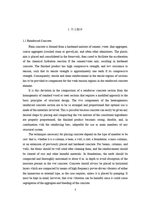
1 外文翻译1.1 Reinforced ConcretePlain concrete is formed from a hardened mixture of cement ,water ,fine aggregate, coarse aggregate (crushed stone or gravel),air, and often other admixtures. The plastic mix is placed and consolidated in the formwork, then cured to facilitate the acceleration of the chemical hydration reaction lf the cement/water mix, resulting in hardened concrete. The finished product has high compressive strength, and low resistance to tension, such that its tensile strength is approximately one tenth lf its compressive strength. Consequently, tensile and shear reinforcement in the tensile regions of sections has to be provided to compensate for the weak tension regions in the reinforced concrete element.It is this deviation in the composition of a reinforces concrete section from the homogeneity of standard wood or steel sections that requires a modified approach to the basic principles of structural design. The two components of the heterogeneous reinforced concrete section are to be so arranged and proportioned that optimal use is made of the materials involved. This is possible because concrete can easily be given any desired shape by placing and compacting the wet mixture of the constituent ingredients are properly proportioned, the finished product becomes strong, durable, and, in combination with the reinforcing bars, adaptable for use as main members of any structural system.The techniques necessary for placing concrete depend on the type of member to be cast: that is, whether it is a column, a bean, a wall, a slab, a foundation. a mass columns, or an extension of previously placed and hardened concrete. For beams, columns, and walls, the forms should be well oiled after cleaning them, and the reinforcement should be cleared of rust and other harmful materials. In foundations, the earth should be compacted and thoroughly moistened to about 6 in. in depth to avoid absorption of the moisture present in the wet concrete. Concrete should always be placed in horizontal layers which are compacted by means of high frequency power-driven vibrators of either the immersion or external type, as the case requires, unless it is placed by pumping. It must be kept in mind, however, that over vibration can be harmful since it could cause segregation of the aggregate and bleeding of the concrete.Hydration of the cement takes place in the presence of moisture at temperatures above 50°F. It is necessary to maintain such a condition in order that the chemical hydration reaction can take place. If drying is too rapid, surface cracking takes place. This would result in reduction of concrete strength due to cracking as well as the failure to attain full chemical hydration.It is clear that a large number of parameters have to be dealt with in proportioning a reinforced concrete element, such as geometrical width, depth, area of reinforcement, steel strain, concrete strain, steel stress, and so on. Consequently, trial and adjustment is necessary in the choice of concrete sections, with assumptions based on conditions at site, availability of the constituent materials, particular demands of the owners, architectural and headroom requirements, the applicable codes, and environmental reinforced concrete is often a site-constructed composite, in contrast to the standard mill-fabricated beam and column sections in steel structures.A trial section has to be chosen for each critical location in a structural system. The trial section has to be analyzed to determine if its nominal resisting strength is adequate to carry the applied factored load. Since more than one trial is often necessary to arrive at the required section, the first design input step generates into a series of trial-and-adjustment analyses.The trial-and –adjustment procedures for the choice of a concrete section lead to the convergence of analysis and design. Hence every design is an analysis once a trial section is chosen. The availability of handbooks, charts, and personal computers and programs supports this approach as a more efficient, compact, and speedy instructional method compared with the traditional approach of treating the analysis of reinforced concrete separately from pure design.1.2 EarthworkBecause earthmoving methods and costs change more quickly than those in any other branch of civil engineering, this is a field where there are real opportunities for the enthusiast. In 1935 most of the methods now in use for carrying and excavating earth with rubber-tyred equipment did not exist. Most earth was moved by narrow rail track, now relatively rare, and the main methods of excavation, with face shovel, backacter, or dragline or grab, though they are still widely used are only a few of the many current methods. To keep his knowledge of earthmoving equipment up to date an engineer must therefore spend tine studying modern machines. Generally the only reliable up-to-date information on excavators, loaders and transport is obtainable from the makers.Earthworks or earthmoving means cutting into ground where its surface is too high ( cuts ), and dumping the earth in other places where the surface is too low ( fills). Toreduce earthwork costs, the volume of the fills should be equal to the volume of the cuts and wherever possible the cuts should be placednear to fills of equal volume so as to reduce transport and double handlingof the fill. This work of earthwork design falls on the engineer who lays out the road since it is the layout of the earthwork more than anything else which decides its cheapness. From the available maps ahd levels, the engineering must try to reach as many decisions as possible in the drawing office by drawing cross sections of the earthwork. On the site when further information becomes available he can make changes in jis sections and layout,but the drawing lffice work will not have been lost. It will have helped him to reach the best solution in the shortest time.The cheapest way of moving earth is to take it directly out of the cut and drop it as fill with the same machine. This is not always possible, but when it canbe done it is ideal, being both quick and cheap. Draglines, bulldozers and face shovels an do this. The largest radius is obtained with the dragline,and the largest tonnage of earth is moved by the bulldozer, though only over short distances.The disadvantages of the dragline are that it must dig below itself, it cannot dig with force into compacted material, it cannot dig on steep slopws, and its dumping and digging are not accurate.Face shovels are between bulldozers and draglines, having a larger radius of action than bulldozers but less than draglines. They are anle to dig into a vertical cliff face in a way which would be dangerous tor a bulldozer operator and impossible for a dragline. Each piece of equipment should be level of their tracks and for deep digs in compact material a backacter is most useful, but its dumping radius is considerably less than that of the same escavator fitted with a face shovel.Rubber-tyred bowl scrapers are indispensable for fairly level digging where the distance of transport is too much tor a dragline or face shovel. They can dig the material deeply ( but only below themselves ) to a fairly flat surface, carry it hundreds of meters if need be, then drop it and level it roughly during the dumping. For hard digging it is often found economical to keep a pusher tractor ( wheeled or tracked ) on the digging site, to push each scraper as it returns to dig. As soon as the scraper is full,the pusher tractor returns to the beginning of the dig to heop to help the nest scraper.Bowl scrapers are often extremely powerful machines;many makers build scrapers of 8 cubic meters struck capacity, which carry 10 m ³ heaped. The largest self-propelledscrapers are of 19 m ³ struck capacity ( 25 m ³ heaped )and they are driven by a tractor engine of 430 horse-powers.Dumpers are probably the commonest rubber-tyred transport since they can also conveniently be used for carrying concrete or other building materials. Dumpers have the earth container over the front axle on large rubber-tyred wheels, and the container tips forwards on most types, though in articulated dumpers the direction of tip can be widely varied. The smallest dumpers have a capacity of about 0.5 m ³, and the largest standard types are of about 4.5 m ³. Special types include the self-loading dumper of up to 4 m ³and the articulated type of about 0.5 m ³. The distinction between dumpers and dump trucks must be remembered .dumpers tip forwards and the driver sits behind the load. Dump trucks are heavy, strengthened tipping lorries, the driver travels in front lf the load and the load is dumped behind him, so they are sometimes called rear-dump trucks.1.3 Safety of StructuresThe principal scope of specifications is to provide general principles and computational methods in order to verify safety of structures. The “ safety factor ”, which according to modern trends is independent of the nature and combination of the materials used, can usually be defined as the ratio between the conditions. This ratio is also proportional to the inverse of the probability ( risk ) of failure of the structure.Failure has to be considered not only as overall collapse of the structure but also as unserviceability or, according to a more precise. Common definition. As the reaching of a “ limit state ” which causes the construction not to accomplish the task it was designed for. There are two categories of limit state :(1)Ultimate limit sate, which corresponds to the highest value of the load-bearing capacity. Examples include local buckling or global instability of the structure; failure of some sections and subsequent transformation of the structure into a mechanism; failure by fatigue; elastic or plastic deformation or creep that cause a substantial change of the geometry of the structure; and sensitivity of the structure to alternating loads, to fire and to explosions.(2)Service limit states, which are functions of the use and durability of the structure. Examples include excessive deformations and displacements without instability; early or excessive cracks; large vibrations; and corrosion.Computational methods used to verify structures with respect to the different safety conditions can be separated into:(1)Deterministic methods, in which the main parameters are considered asnonrandom parameters.(2)Probabilistic methods, in which the main parameters are considered as random parameters.Alternatively, with respect to the different use of factors of safety, computational methods can be separated into:(1)Allowable stress method, in which the stresses computed under maximum loads are compared with the strength of the material reduced by given safety factors.(2)Limit states method, in which the structure may be proportioned on the basis of its maximum strength. This strength, as determined by rational analysis, shall not be less than that required to support a factored load equal to the sum of the factored live load and dead load ( ultimate state ).The stresses corresponding to working ( service ) conditions with unfactored live and dead loads are compared with prescribed values ( service limit state ) . From the four possible combinations of the first two and second two methods, we can obtain some useful computational methods. Generally, two combinations prevail:(1)deterministic methods, which make use of allowable stresses.(2)Probabilistic methods, which make use of limit states.The main advantage of probabilistic approaches is that, at least in theory, it is possible to scientifically take into account all random factors of safety, which are then combined to define the safety factor. probabilistic approaches depend upon :(1) Random distribution of strength of materials with respect to the conditions of fabrication and erection ( scatter of the values of mechanical properties through out the structure );(2) Uncertainty of the geometry of the cross-section sand of the structure ( faults and imperfections due to fabrication and erection of the structure );(3) Uncertainty of the predicted live loads and dead loads acting on the structure;(4)Uncertainty related to the approximation of the computational method used ( deviation of the actual stresses from computed stresses ).Furthermore, probabilistic theories mean that the allowable risk can be based on several factors, such as :(1) Importance of the construction and gravity of the damage by its failure;(2)Number of human lives which can be threatened by this failure;(3)Possibility and/or likelihood of repairing the structure;(4) Predicted life of the structure.All these factors are related to economic and social considerations such as:(1) Initial cost of the construction;(2) Amortization funds for the duration of the construction;(3) Cost of physical and material damage due to the failure of the construction;(4) Adverse impact on society;(5) Moral and psychological views.The definition of all these parameters, for a given safety factor, allows construction at the optimum cost. However, the difficulty of carrying out a complete probabilistic analysis has to be taken into account. For such an analysis the laws of the distribution of the live load and its induced stresses, of the scatter of mechanical properties of materials, and of the geometry of the cross-sections and the structure have to be known. Furthermore, it is difficult to interpret the interaction between the law of distribution of strength and that of stresses because both depend upon the nature of the material, on the cross-sections and upon the load acting on the structure. These practical difficulties can be overcome in two ways. The first is to apply different safety factors to the material and to the loads, without necessarily adopting the probabilistic criterion. The second is an approximate probabilistic method which introduces some simplifying assumptions ( semi-probabilistic methods ) .From《CANADIAN JOURNAL OF CIVIL ENGINEERING》。
Spring 框架简介外文翻译

xxxx大学xxx学院毕业设计(论文)外文文献翻译系部xxxx专业xxxx学生姓名xxxx 学号xxxx指导教师xxxx 职称xxxxIntroducing the Spring FrameworkThe Spring Framework: a popular open source application framework that addresses many of the issues outlined in this book. This chapter will introduce the basic ideas of Spring and dis-cuss the central “bean factory” lightweight Inversion-of-Control (IoC) container in detail.Spring makes it particularly easy to implement lightweight, yet extensible, J2EE archi-tectures. It provides an out-of-the-box implementation of the fundamental architectural building blocks we recommend. Spring provides a consistent way of structuring your applications, and provides numerous middle tier features that can make J2EE development significantly easier and more flexible than in traditional approaches.The basic motivations for Spring are:To address areas not well served by other frameworks. There are numerous good solutions to specific areas of J2EE infrastructure: web frameworks, persistence solutions, remoting tools, and so on. However, integrating these tools into a comprehensive architecture can involve significant effort, and can become a burden. Spring aims to provide an end-to-end solution, integrating spe-cialized frameworks into a coherent overall infrastructure. Spring also addresses some areas that other frameworks don’t. For example, few frameworks address generic transaction management, data access object implementation, and gluing all those things together into an application, while still allowing for best-of-breed choice in each area. Hence we term Spring an application framework, rather than a web framework, IoC or AOP framework, or even middle tier framework.To allow for easy adoption. A framework should be cleanly layered, allowing the use of indi-vidual features without imposing a whole worldview on the application. Many Spring features, such as the JDBC abstraction layer or Hibernate integration, can be used in a library style or as part of the Spring end-to-end solution.To deliver ease of use. As we’ve noted, J2EE out of the box is relatively hard to use to solve many common problems. A good infrastructure framework should make simple tasks simple to achieve, without forcing tradeoffs for future complex requirements (like distributed transactions) on the application developer. It should allow developers to leverage J2EE services such as JTA where appropriate, but to avoid dependence on them in cases when they are unnecessarily complex.To make it easier to apply best practices. Spring aims to reduce the cost of adhering to best practices such as programming to interfaces, rather than classes, almost to zero. However, it leaves the choice of architectural style to the developer.Non-invasiveness. Application objects should have minimal dependence on the framework. If leveraging a specific Spring feature, an object should depend only on that particular feature, whether by implementing a callback interface or using the framework as a class library. IoC and AOP are the key enabling technologies for avoiding framework dependence.Consistent configuration. A good infrastructure framework should keep application configuration flexible and consistent, avoiding the need for custom singletons and factories. A single style should be applicable to all configuration needs, from the middle tier to web controllers.Ease of testing. Testing either whole applications or individual application classes in unit tests should be as easy as possible. Replacing resources or application objects with mock objects should be straightforward.To allow for extensibility. Because Spring is itself based on interfaces, rather than classes, it is easy to extend or customize it. Many Spring components use strategy interfaces, allowing easy customization.A Layered Application FrameworkChapter 6 introduced the Spring Framework as a lightweight container, competing with IoC containers such as PicoContainer. While the Spring lightweight container for JavaBeans is a core concept, this is just the foundation for a solution for all middleware layers.Basic Building Blockspring is a full-featured application framework that can be leveraged at many levels. It consists of multi-ple sub-frameworks that are fairly independent but still integrate closely into a one-stop shop, if desired. The key areas are:Bean factory. The Spring lightweight IoC container, capable of configuring and wiring up Java-Beans and most plain Java objects, removing the need for custom singletons and ad hoc configura-tion. Various out-of-the-box implementations include an XML-based bean factory. The lightweight IoC container and its Dependency Injection capabilities will be the main focus of this chapter.Application context. A Spring application context extends the bean factory concept by adding support for message sources and resource loading, and providing hooks into existing environ-ments. Various out-of-the-box implementations include standalone application contexts and an XML-based web application context.AOP framework. The Spring AOP framework provides AOP support for method interception on any class managed by a Spring lightweight container.It supports easy proxying of beans in a bean factory, seamlessly weaving in interceptors and other advice at runtime. Chapter 8 dis-cusses the Spring AOP framework in detail. The main use of the Spring AOP framework is to provide declarative enterprise services for POJOs.Auto-proxying. Spring provides a higher level of abstraction over the AOP framework and low-level services, which offers similar ease-of-use to .NET within a J2EE context. In particular, the provision of declarative enterprise services can be driven by source-level metadata.Transaction management. Spring provides a generic transaction management infrastructure, with pluggable transaction strategies (such as JTA and JDBC) and various means for demarcat-ing transactions in applications. Chapter 9 discusses its rationale and the power and flexibility that it offers.DAO abstraction. Spring defines a set of generic data access exceptions that can be used for cre-ating generic DAO interfaces that throw meaningful exceptions independent of the underlying persistence mechanism. Chapter 10 illustrates the Spring support for DAOs in more detail, examining JDBC, JDO, and Hibernate as implementation strategies.JDBC support. Spring offers two levels of JDBC abstraction that significantly ease the effort of writing JDBC-based DAOs: the org.springframework.jdbc.core package (a template/callback approach) and the org.springframework.jdbc.object package (modeling RDBMS operations as reusable objects). Using the Spring JDBC packages can deliver much greater pro-ductivity and eliminate the potential for common errors such as leaked connections, compared with direct use of JDBC. The Spring JDBC abstraction integrates with the transaction and DAO abstractions.Integration with O/R mapping tools. Spring provides support classesfor O/R Mapping tools like Hibernate, JDO, and iBATIS Database Layer to simplify resource setup, acquisition, and release, and to integrate with the overall transaction and DAO abstractions. These integration packages allow applications to dispense with custom ThreadLocal sessions and native transac-tion handling, regardless of the underlying O/R mapping approach they work with.Web MVC framework. Spring provides a clean implementation of web MVC, consistent with the JavaBean configuration approach. The Spring web framework enables web controllers to be configured within an IoC container, eliminating the need to write any custom code to access business layer services. It provides a generic DispatcherServlet and out-of-the-box controller classes for command and form handling. Request-to-controller mapping, view resolution, locale resolution and other important services are all pluggable, making the framework highly extensi-ble. The web framework is designed to work not only with JSP, but with any view technology, such as Velocity—without the need for additional bridges. Chapter 13 discusses web tier design and the Spring web MVC framework in detail.Remoting support. Spring provides a thin abstraction layer for accessing remote services without hard-coded lookups, and for exposing Spring-managed application beans as remote services. Out-of-the-box support is included for RMI, Caucho’s Hessian and Burlap web service protocols, and WSDL Web Services via JAX-RPC. Chapter 11 discusses lightweight remoting.While Spring addresses areas as diverse as transaction management and web MVC, it uses a consistent approach everywhere. Once you have learned the basic configuration style, you will be able to apply it in many areas. Resources, middle tier objects, and web components are all set up using the same bean configuration mechanism. You can combine your entireconfiguration in one single bean definition file or split it by application modules or layers; the choice is up to you as the application developer. There is no need for diverse configuration files in a variety of formats, spread out across the application.Spring on J2EEAlthough many parts of Spring can be used in any kind of Java environment, it is primarily a J2EE application framework. For example, there are convenience classes for linking JNDI resources into a bean factory, such as JDBC DataSources and EJBs, and integration with JTA for distributed transaction management. In most cases, application objects do not need to work with J2EE APIs directly, improving reusability and meaning that there is no need to write verbose, hard-to-test, JNDI lookups.Thus Spring allows application code to seamlessly integrate into a J2EE environment without being unnecessarily tied to it. You can build upon J2EE services where it makes sense for your application, and choose lighter-weight solutions if there are no complex requirements. For example, you need to use JTA as transaction strategy only if you face distributed transaction requirements. For a single database, there are alternative strategies that do not depend on a J2EE container. Switching between those transac-tion strategies is merely a matter of configuration; Spring’s consistent abstraction avoids any need to change application code.Spring offers support for accessing EJBs. This is an important feature (and relevant even in a book on “J2EE without EJB”) because the use of dynamic proxies as codeless client-side business delegates means that Spring can make using a local stateless session EJB an implementation-level, rather than a fundamen-tal architectural, choice.Thus if you want to use EJB, you can within a consistent architecture; however, you do not need to make EJB the cornerstone of your architecture. This Spring feature can make devel-oping EJB applications significantly faster, because there is no need to write custom code in service loca-tors or business delegates. Testing EJB client code is also much easier, because it only depends on the EJB’s Business Methods interface (which is not EJB-specific), not on JNDI or the EJB API.Spring also provides support for implementing EJBs, in the form of convenience superclasses for EJB implementation classes, which load a Spring lightweight container based on an environment variable specified in the ejb-jar.xml deployment descriptor. This is a powerful and convenient way of imple-menting SLSBs or MDBs that are facades for fine-grained POJOs: a best practice if you do choose to implement an EJB application. Using this Spring feature does not conflict with EJB in any way—it merely simplifies following good practice.Introducing the Spring FrameworkThe main aim of Spring is to make J2EE easier to use and promote good programming practice. It does not reinvent the wheel; thus you’ll find no logging packages in Spring, no connection pools, no distributed transaction coordinator. All these features are provided by other open source projects—such as Jakarta Commons Logging (which Spring uses for all its log output), Jakarta Commons DBCP (which can be used as local DataSource), and ObjectWeb JOTM (which can be used as transaction manager)—or by your J2EE application server. For the same reason, Spring doesn’t provide an O/R mapping layer: There are good solutions for this problem area, such as Hibernate and JDO.Spring does aim to make existing technologies easier to use. For example, although Spring is not in the business of low-level transactioncoordination, it does provide an abstraction layer over JTA or any other transaction strategy. Spring is also popular as middle tier infrastructure for Hibernate, because it provides solutions to many common issues like SessionFactory setup, ThreadLocal sessions, and exception handling. With the Spring HibernateTemplate class, implementation methods of Hibernate DAOs can be reduced to one-liners while properly participating in transactions.The Spring Framework does not aim to replace J2EE middle tier services as a whole. It is an application framework that makes accessing low-level J2EE container ser-vices easier. Furthermore, it offers lightweight alternatives for certain J2EE services in some scenarios, such as a JDBC-based transaction strategy instead of JTA when just working with a single database. Essentially, Spring enables you to write appli-cations that scale down as well as up.Spring for Web ApplicationsA typical usage of Spring in a J2EE environment is to serve as backbone for the logical middle tier of a J2EE web application. Spring provides a web application context concept, a powerful lightweight IoC container that seamlessly adapts to a web environment: It can be accessed from any kind of web tier, whether Struts, WebWork, Tapestry, JSF, Spring web MVC, or a custom solution.The following code shows a typical example of such a web application context. In a typical Spring web app, an applicationContext.xml file will reside in the WEB-INF directory, containing bean defini-tions according to the “spring-beans” DTD. In such a bean definition XML file, business objects and resources are defined, for example, a “myDataSource” bean, a “myInventoryManager” bean, and a “myProductManager” bean. Spring takes care of their configuration, their wiring up, and their lifecycle.<beans><bean id=”myDataSource” class=”org.springframework.jdbc. datasource.DriverManagerDataSource”><property name=”driverClassName”> <value>com.mysql.jdbc.Driver</value></property> <property name=”url”><value>jdbc:mysql:myds</value></property></bean><bean id=”myInventoryManager” class=”ebusiness.DefaultInventoryManager”> <property name=”dataSource”><ref bean=”myDataSource”/> </property></bean><bean id=”myProductManager” class=”ebusiness.DefaultProductManager”><prop erty name=”inventoryManager”><ref bean=”myInventoryManager”/> </property><property name=”retrieveCurrentStock”> <value>true</value></property></bean></beans>By default, all such beans have “singleton” scope: one instance per context. The “myInventoryManager” bean will automatically be wired up with the defined DataSource, while “myProductManager” will in turn receive a reference to the “myInventoryManager” bean. Those objects (traditionally called “beans” in Spring terminology) need to expose only the corresponding bean properties or constructor arguments (as you’ll see later in this chapter); they do not have to perform any custom lookups.A root web application context will be loaded by a ContextLoaderListener that is defined in web.xml as follows:<web-app><listener> <listener-class>org.springframework.web.context.ContextLoaderListener</listener-class></listener>...</web-app>After initialization of the web app, the root web application context will be available as a ServletContext attribute to the whole web application, in the usual manner. It can be retrieved from there easily via fetching the corresponding attribute, or via a convenience method in org.springframework.web. context.support.WebApplicationContextUtils. This means that the application context will be available in any web resource with access to the ServletContext, like a Servlet, Filter, JSP, or Struts Action, as follows:WebApplicationContext wac = WebApplicationContextUtils.getWebApplicationContext(servletContext);The Spring web MVC framework allows web controllers to be defined as JavaBeans in child application contexts, one per dispatcher servlet. Such controllers can express dependencies on beans in the root application context via simple bean references. Therefore, typical Spring web MVC applications never need to perform a manual lookup of an application context or bean factory, or do any other form of lookup.Neither do other client objects that are managed by an application context themselves: They can receive collaborating objects as bean references.The Core Bean FactoryIn the previous section, we have seen a typical usage of the Spring IoC container in a web environment: The provided convenience classes allow for seamless integration without having to worry about low-level container details. Nevertheless, it does help to look at the inner workings to understand how Spring manages the container. Therefore, we will now look at the Spring bean container in more detail, starting at the lowest building block: the bean facto ry. Later, we’ll continue with resource setup and details on the application context concept.One of the main incentives for a lightweight container is to dispense with the multitude of custom facto-ries and singletons often found in J2EE applications. The Spring bean factory provides one consistent way to set up any number of application objects, whether coarse-grained components or fine-grained busi-ness objects. Applying reflection and Dependency Injection, the bean factory can host components that do not need to be aware of Spring at all. Hence we call Spring a non-invasive application framework.Fundamental InterfacesThe fundamental lightweight container interface is org.springframework.beans.factory.Bean Factory. This is a simple interface, which is easy to implement directly in the unlikely case that none of the implementations provided with Spring suffices. The BeanFactory interface offers two getBean() methods for looking up bean instances by String name, with the option to check for a required type (and throw an exception if there is a type mismatch).public interface BeanFactory {Object getBean(String name) throws BeansException;Object getBean(String name, Class requiredType) throws BeansException;boolean containsBean(String name);boolean isSingleton(String name) throws NoSuchBeanDefinitionException;String[] getAliases(String name) throws NoSuchBeanDefinitionException;}The isSingleton() method allows calling code to check whether the specified name represents a sin-gleton or prototype bean definition. In the case of a singleton bean, all calls to the getBean() method will return the same object instance. In the case of a prototype bean, each call to getBean() returns an inde-pendent object instance, configured identically.The getAliases() method will return alias names defined for the given bean name, if any. This mecha-nism is used to provide more descriptive alternative names for beans than are permitted in certain bean factory storage representations, such as XML id attributes.The methods in most BeanFactory implementations are aware of a hierarchy that the implementation may be part of. If a bean is not foundin the current factory, the parent factory will be asked, up until the root factory. From the point of view of a caller, all factories in such a hierarchy will appear to be merged into one. Bean definitions in ancestor contexts are visible to descendant contexts, but not the reverse.All exceptions thrown by the BeanFactory interface and sub-interfaces extend org.springframework. beans.BeansException, and are unchecked. This reflects the fact that low-level configuration prob-lems are not usually recoverable: Hence, application developers can choose to write code to recover from such failures if they wish to, but should not be forced to write code in the majority of cases where config-uration failure is fatal.Most implementations of the BeanFactory interface do not merely provide a registry of objects by name; they provide rich support for configuring those objects using IoC. For example, they manage dependen-cies between managed objects, as well as simple properties. In the next section, we’ll look at how such configuration can be expressed in a simple and intuitive XML structure.The sub-interface org.springframework.beans.factory.ListableBeanFactory supports listing beans in a factory. It provides methods to retrieve the number of beans defined, the names of all beans, and the names of beans that are instances of a given type:public interface ListableBeanFactory extends BeanFactory {int getBeanDefinitionCount();String[] getBeanDefinitionNames();String[] getBeanDefinitionNames(Class type);boolean containsBeanDefinition(String name);Map getBeansOfType(Class type, boolean includePrototypes,boolean includeFactoryBeans) throws BeansException}The ability to obtain such information about the objects managed by a ListableBeanFactory can be used to implement objects that work with a set of other objects known only at runtime.In contrast to the BeanFactory interface, the methods in ListableBeanFactory apply to the current factory instance and do not take account of a hierarchy that the factory may be part of. The org.spring framework.beans.factory.BeanFactoryUtils class provides analogous methods that traverse an entire factory hierarchy.There are various ways to leverage a Spring bean factory, ranging from simple bean configuration to J2EE resource integration and AOP proxy generation. The bean factory is the central, consistent way of setting up any kind of application objects in Spring, whether DAOs, business objects, or web controllers. Note that application objects seldom need to work with the BeanFactory interface directly, but are usu-ally configured and wired by a factory without the need for any Spring-specific code.For standalone usage, the Spring distribution provides a tiny spring-core.jar file that can be embed-ded in any kind of application. Its only third-party dependency beyond J2SE 1.3 (plus JAXP for XML parsing) is the Jakarta Commons Logging API.The bean factory is the core of Spring and the foundation for many other services that the framework offers. Nevertheless, the bean factory can easily be used stan-dalone if no other Spring services are required.Derivative:networkSpring 框架简介Spring框架:这是一个流行的开源应用框架,它可以解决很多问题。
框架结构外国文学名词解释
框架结构外国文学名词解释
当涉及到外国文学的框架结构和相关名词解释时,以下是一些常见的解释:
1.框架结构(Framework Structure):指文学作品中的整体组织结构,包括章节划分、故事线索、人物关系等。
框架结构可以影响故事的发展和叙事方式。
2.叙事结构(Narrative Structure):指文学作品中故事的组织方式,包括线性叙事、非线性叙事、回忆叙事等。
叙事结构可以影响读者对故事的理解和感受。
3.主题(Theme):指文学作品中所探讨的核心思想、价值观或意义。
主题可以是关于人类生活、社会问题、道德困境等方面的思考。
4.人物角色(Character):指文学作品中的虚构人物,他们通过言行和情感表达来推动故事的发展。
人物角色可以是主角、配角、反派等。
5.符号(Symbol):指在文学作品中用来代表或象征特定意义的事物、动作或情节。
符号可以有多重解读,丰富了作品的意义和深度。
5.风格(Style):指作家在写作中所采用的语言、表达方式和叙述手法。
风格可以体现作家的个人特色,对作品的氛围和情感产生影响。
7.文学流派(Literary Genre):指根据作品的特点和风格进行分类的文学类别,如小说、诗歌、戏剧、散文等。
不同的文学流派有着不同的写作规范和特点。
这些是外国文学框架结构和相关名词的一些解释。
当涉及到具体的作品或文学流派时,可能会有更多的特定名词和解释。
框架结构抗震设计外文翻译
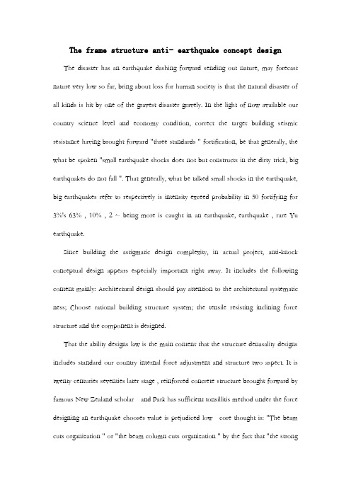
The frame structure anti- earthquake concept design The disaster has an earthquake dashing forward sending out nature, may forecast nature very low so far, bring about loss for human society is that the natural disaster of all kinds is hit by one of the gravest disaster gravely. In the light of now available our country science level and economy condition, correct the target building seismic resistance having brought forward "three standards " fortification, be that generally, the what be spoken "small earthquake shocks does not but constructs in the dirty trick, big earthquakes do not fall ". That generally, what be talked small shocks in the earthquake, big earthquakes refer to respectively is intensity exceed probability in 50 fortifying for 3%'s 63% , 10% , 2 ~ being more is caught in an earthquake, earthquake , rare Yu earthquake.Since building the astigmatic design complexity, in actual project, anti-knock conceptual design appears especially important right away. It includes the following content mainly: Architectural design should pay attention to the architectural systematic ness; Choose rational building structure system; the tensile resisting inclining force structure and the component is designed.That the ability designs law is the main content that the structure denasality designs includes standard our country internal force adjustment and structure two aspect. It is twenty centuries seventies later stage , reinforced concrete structure brought forward by famous New Zealand scholar and Park has sufficient tonsillitis method under the force designing an earthquake chooses value is prejudiced low core thought is: "The beam cuts organization " or "the beam column cuts organization " by the fact that "the strongweak post beam " guides structure to take form; Avoid structure by "strong weak scissors turn " before reach estimate that shearing happened in the denasality in the ability front destroy; Turn an ability and consume an ability by the fact that necessary structure measure makes the location may form the plasticity hinge have the necessary plasticity. Make structure have the necessary tonsillitis from all above three aspect guarantee. That framed structure is the common structure form, whose senility certainly designs that, is to embody from about this three aspect also mainly.1, Strong pillar weak beamDriving force reaction analysis indicates structure; architectural deformability is connected with to destroying mechanism. Common have three kinds model’s consume energy organization ", beam hinge organization ““, post hinge organization ““, beam column hinge organization "."Beam hinge organization " and "beam column hinge organization " Lang Xian knuckle under , may let the entire frame have distribution and energy consumption heavierthan big internal forces ability, limit tier displacement is big , plasticity hinge quantity is many , the hinge does not lose efficacy but the structure entirety does not lose efficacy because of individual plasticity. The as a result anti-knock function is easy to be that the armored concrete is ideal consume energy organization. Being that our country norm adopts allows a pillar , the shearing force wall puts up the hinge beam column hinge scheme, taking place adopting "strong relative weak post beam " measure , postponing a pillar cuts time. Weak tier of post hinge organization possibility appear on unable complete trouble shooting but , require that the axis pressure restricting a pillar compares as a result, architectural weakness prevents necessary timefrom appearing tier by the fact that Cheng analysis law judges now and then, post hinge organization.Are that V. I. P. is to enhance the pillar bending resistance , guidance holds in the beam appear first, the plasticity cuts our "strong common weak post beam " adjustment measure. Before plasticity hinge appearing on structure, structure component Yin La District concrete dehiscence and pressure area concrete mistake elasticity character, every component stiffness reduces a reinforced bar will do with the cementation degeneration between the concrete. That stiffness reduces a beam is relatively graver than accepting the pillar pressing on , structure enhances from initial shearing type deformation to curved scissors shape deformation transition , curved post inner regulation proportion really more curved than beam; The at the same time architectural period is lengthened, size affecting the participation modulus shaking a type respectively to structure's; Change happened in the earthquake force modulus , lead to the part pillar bend regulation enhancing, feasible beam reality knuckles under intensity rise , the post inner bends regulation when plasticity hinge appearing on thereby feasible beam enhancing since structure cause and the people who designs the middle reinforced bar's are to enhance.. And after plasticity hinge appearing on structure, same existence having above-mentioned cause, structure knuckles under mistake elasticity in the day after tomorrow process being that process , post that the earthquake enhances strenuously further bend regulation enhancing with earthquake force but enhance. The force arouses an earthquake overturn force moment having changed the actual post inner axis force. We knuckle under the ability lessening than axis pressure in standardizing being limitedto be able to ensure that the pillar also can lead to a pillar in big the bias voltage range inner , axis force diminution like value. The anti-knock norm is stipulated: Except that the frame top storey and post axis pressure are compared to the strut beam and frame pillar being smaller than person and frame, post holds curved regulation designing that value should accord with difference being,that first order takes , the two stage takes , grade-three takes 1.1. 9 degree and one step of framed structure still responds to coincidence, ,intensity standard value ascertains that according to matching reinforced bar area and material really. The bottom post axis is strenuously big, the ability that the plasticity rotates dispatches, be that pressure collapses after avoiding a foot stall producing a hinge, one, two, three steps of framed structure bottom, post holds cross section constituting curved regulation designing that value takes advantage of that , compose in reply 1.15 in order to enhancing a modulus respectively. Combination of the corner post adjustment queen bends regulation still should take advantage of that not to be smaller than 's modular. Curved regulation designs that value carries out adjustment to one-level anti-knock grade shearing force wall limb cross section combination , force the plasticity hinge to appear to reinforce location in the wall limb bottom, the bottom reinforces location and all above layer of curved regulation designing that value takes wall limb bottom cross section constituting curved regulation designing value , other location multiplies 's by to enhance a modulus. Prop up anti-knock wall structure to part frame, bottom-end , whose curved combination regulation design value respond to one, two steps of frame pillars post upper end and bottom post take advantage of that composes in reply 1.25 in orderto enhancing a modulus respectively. All above "strong weak post beam” adjustment measure, reaction analysis indicates , big satisfied fundamental earthquakes demand no upside down course nonlinearity driving force. Reinforced bar spending area, the beam in 7 is controlled from gravity load, the post reinforced bar matches’ tendon rates basically from the minimum under the control of. Have enhanced post Liana Xiang all round resisting the curved ability. At the same time, 7 degree of area exactly curved regulation plasticity hinge appears on disaster very much, plays arrive at advantageous role to fighting against big earthquakes. In 9 degree of area, adopt reality to match reinforced bar area and material bending regulation within intensity standard value calculation post, structural beam reinforced bar enhancing same lead to enhancing bending regulation within post designing value, under importing in many waves, the beam holds the plasticity hinge rotating developing greatly, more sufficient, post holds the plasticity hinge developing insufficiency, rotate less. Design demand with the beam. Reaction and 9 degree are about the same to 8 degree of area , whose big earthquake displacement , that post holds the plasticity hinge is bigger than rotating 9 degree much but, the beam holds the plasticity hinge appearing sufficient but rotate small, as a result "strong weak post beam " effect is not obvious , curved regulation enhances a modulus ought to take , this waits for improving and perfecting going a step further when the grade suggesting that 8 degree of two stage is anti-knock in connection with the expert.2, Strong shear weak curved"Strong weak scissors turn” is that the plasticity cuts cross section for guarantee on reach anticipate that shearing happened in the mistake elastic-deformation prior todestroy. As far as common structure be concerned, main behaviors holds in the beam, post holds, the shearing force wall bottom reinforces area , shearing force wall entrance to a cave company beam tools , beam column node core area. Show mainly with being not that seismic resistance is compared with each other, strengthening measure in improving the effect shearing force; Aspect adjusting a shear bearing the weight of two forces.1)effect shearing forceOne, two, three-level frame beam and anti-knock wall middle stride over high ratio greater than company beam, shearing force design value among them, first order choose , two stage choose , three-level choose , first order framed structure and 9 Due Shan respond to coincidence. Coincidence one, two, three steps of frame post and frame pillar , shearing force being designed being worth taking among them, one step , taking , three steps of take , one-level framed structure and 9 Due Shank two steps responding to. One, two, three steps of anti-knock walls bottom reinforces location the shearing force designs that value is among them, first order takes , the two stage takes , grade-three takes , 9 Dud Shank respond to coincidence. The node core area seismic resistance the beam column node , one, two steps of anti-knock grades are carried out is born the weight of force checking calculation by the scissors , should accord with anti-knock structure measure about 3 step, correct 9 degree of fortify and one-level anti-knock grade framed structure, think to the beam end the plasticity hinge already appears , the node shearing force holds reality completely from the beam knuckling under curved regulation decision , hold reality according to the beam matching reinforced bar covering an area of the growing modulus that intensity standard value calculation, takes advantage of that at the same time with with material. Other first order holds curved regulation according to the beamdesigning that value secretly schemes against , the shearing force enhances a modulus being , the two stage is .2) Shear formulaThe continuous beam of armored concrete and the cantilever beam are born theweight of at home and abroad under low repeated cycle load effect by the scissors the force experiment indicates the main cause pooling efforts and reducing even if tendon dowel force lessening is that the beam is born the weight of a force by the scissors, concrete scissors pressure area lessening shearing an intensity, tilted rift room aggregate bite. Scissors bear the weight of a norm to the concrete accepting descending strenuously being 60% be not anti-knock, the reinforced bar item does not reduce. By the same token, the experiment indicates to insisting to intimidate post with that the force is born the weight of by the scissors, loading makes post the force be born the weight of by the scissors reducing 10% ~ again and again 30%, the item arouses , adopts practice identical with the beam mainly from the concrete. The experiment is indicated to shearing force wall, whose repeated loading breaks the subtraction modulus up than monotony increases be loaded with force lessening is born the weight of by the scissors 15% ~ 20%, adopts to be not that seismic resistance is born the weight of by the scissors energy times 's. Two parts accept the pressure pole strenuously tilted from the concrete is born the weight of by the scissors and horizontal stirrup of beam column node seismic resistance cutting the expert who bears the weight of force composition , is connected with have given a relevance out formula.Tilted for preventing the beam , post , company beam , shearing force wall , node from happening pressure is destroyed, we have stipulated upper limits force upper limit to be born the weight of by the scissors , have stipulated to match hoop rate’s namely to accepting scissors cross section.Reaction analysis indicates strong weak curved scissors requests; all above measure satisfies basically by mistake elasticity driving force. The plasticity rotates because of anti-knock grade of two stage beam column under big earthquakes still very big , suggest that the shearing force enhances a modulus is bigger than having there is difference between one step unsuitably in connection with the expert, to the beam choose is fairly good , ought to take ~ to post . It's the rationality taking value remains to be improved and perfected in going a step further.Require that explanatory being , the beam column node accept a force very complicated , need to ensure that beam column reinforced bar reliability in the node is anchoring , hold occurrence bending resistance at the same time in the beam column destroying front, shearing happened in the node destroy, whose essence should belong to "strong weak curved scissors" categories. The node carries out adjustment on one, two steps of anti-knock grades shearing force and, only, the person enhances a modulus be are minor than post, ratio post also holds structure measure a little weak. As a result ", more strong node “statement, is not worth it encourage.3) Structure measureStructure measure is a beam, post, the shearing force wall plasticity cuts the guarantee that area asks to reach the plasticity that reality needs turning ability and consuming ability. Its "strong with "strong weak scissors turn ", weak post beam " correlates, a arc hitectural denasality of guarantee.”Strong weak scissors turn " is a prerequisite for ensuring that the plasticity hinge turns an ability and consumes an ability; Strict "strong weak post beam " degree, the measure affecting corresponding structure, if put strict "strong weak post beam " into practice, ensure that the pillardoes not appear than the plasticity hinge, corresponding axis pressure waiting for structure measure to should be a little loose right away except the bottom. Our country adopts "the st rong relative weak post beam”, delays a pillar going beyond the hinge time, therefore needing to adopt stricter structure measure.①the beam structure measure beam plasticity hinge cross section senility and many factors match tendon rates and the rise knuckling under an intensity but reduce in connection with cross section tensile, with the reinforced bar being pulled; The reinforced bar matches tendon rates and concrete intensity rise but improve with being pressed on, width enhances but enhances with cross section; Plasticity hinge area stirrup can guard against the pressure injustice releasing a tendon , improve concrete limit pressure strain , arrest tilted rift carrying out , fight against a shearing force , plasticity hinge deformation and consume an ability bring into full play, That deck-molding is stridden over is smaller than exceeding , shearing deformation proportion is increasingly big, the gentility destroying , using the tilted rift easy to happen reduces. The beam has led low even if the tendon matches hoop, the reinforced bar may knuckle under after Lang Kai cracks break up by pulling even. As a result, the norm matches tendon rates to the beam even if the tendon maximum matches tendon rates and minimum , the stirrup encryption District length , maximal spacing , minimal diameter , maximal limb lead all have strict regulations from when, volume matches hoop. Being bending regulation , the guarantee cross section denasality , holding to the beam possibly for the end fighting against a beam to pull the pressure reinforced bar area ratio make restrict. Stride over height at the same time, to minimal beam width, than, aspect ratio has done regulation.② the post structure measureFor post bending a type accepting the force component, axis pressure than to the denasality and consuming to be able to, nature effect is bigger. Destroy axis pressure than big bias voltages happened in the pillar hour, component deformation is big , gentility energy nature easy to only consume, reduces; Nature is growing with axis pressure than enhancing , consuming an energy, but the gentility sudden drop, moreover the stirrup diminishes to the gentility help. Readjust oneself to a certain extent to adopt the pillar, main guarantee it's tonsillitis that the low earthquake designs strenuously, but consuming energy sex to second. The pressure ratio has made a norm to the axis restricting, can ensure that within big bias voltages range in general. Stirrup same get the strain arriving at big roles, restraining the longitudinal tendon, improving concrete pressure, deter the tilted rift from developing also to the denasality. Be to match tendon symmetrically like post, the person leads feeling bigger , as big , becoming deformed when the pillar knuckles under more even if the tendon matches tendon , the tensile finishes exceeding. As a result, the tendon minimum matches tendon rates, the stirrup encryption District length, maximal spacing, minimal diameter, maximal limb lead having made strict regulations out from when, and volume matches hoop to the pillar jumping. At the same time, aspect ratio , scissors to the pillar have stridden over a ratio , minimal altitude of cross section , width have done out regulation, to improve the anti-knock function.③ Node structure measureThe node is anchoring beam column reinforced bar area, effect is very big tostructure function. Be under swear to act on earthquake and the vertical stroke to load, area provides necessary constraint to node core when node core area cuts pressure low than slanting, keep the node fundamental shear ability under disadvantageous condition, make a beam column anchoring even if the tendon is reliable, match hoop rates to node core area maximal spacing of stirrup, minimal diameter, volume having done out regulation. The beam column is main node structure measure content even if tendon reliability in the node is anchoring. Have standardized to beam tendon being hit by the node diameter; Release the anchoring length of tendon to the beam column; anchoring way all has detailed regulation.To sum up ,; Framed structure is to pass "the design plan calculating and coming realize structure measure the ability running after beam hinge organization" mainly thereby, realize "the small earth—quake shocks does not but constructs in the dirty trick, big earthquakes do not fall " three standards to-en fortifying target's. References.框架结构抗震设计地震灾害具有突发性,至今可预报性很低,给人类造成的损失严峻,是各类灾中最严峻的灾害之一。
框架结构的抗震设计思路外文文献翻译
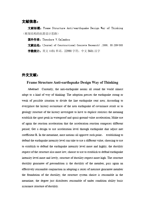
文献信息:文献标题:Frame Structure Anti-earthquake Design Way of Thinking (框架结构的抗震设计思路)国外作者:Theodore V.Galambos文献出处:《Journal of Constructional Concrete Research》,2000, 55:289-303 字数统计:英文4451单词,22990字符;中文5601汉字外文文献:Frame Structure Anti-earthquake Design Way of ThinkingAbstract Currently, the anti-earthquake norms all round the world almost adopt to a kind of way of thinking: The adoption presses the earthquake strong or weak of possible situation to divide the line earthquake cent area; According to everyplace the history occurrence of the area earthquake of covariance result or to geology structure of the history investigate to have to explicit statistics the meaning establish the sport peak in waterproof and quasi-ground value acceleration; Make use of again the reaction acceleration that the acceleration reaction composes different period; Get a design to use acceleration level through earthquake dint adjust met coefficient R. In the meantime, most nations all approve such point,establishing to defend the earthquake intensity level can take to use a different value, choosing to use to establish to defend the earthquake intensity level more and highly, the ductility request of the structure also more low, choose to use to establish to defend earthquake intensity level more and lowly, structure of ductility request more high. The structure ductility guarantee of precondition is the ductility of the member, pass again an effectively reasonable conjunction in adopting a series of measure guarantee member the foundation of the ductility, the structure system choice is reasonable in the meantime, the degree just distributes reasonable of under condition ability basic assurance structure of ductility.Keywords: frame structure; anti-earthquake design; design way of thinking1.Simple Review of Anti-earthquake Design Way of ThinkingThe development that constructs the structure anti- earthquake is along with people all the earthquake move with the structure characteristic of the understanding is continuously thorough but develop gradually, however, from is born up to now the history of a hundred years, have mostly several to develop a stage as follows:(1) Quiet dint stage: It first from a Japanese professor passed to harm to prognosticate the anti- earthquake design theories that put forward with the theories understanding at that time to the limited earthquake, being applicable to only just rigid body structure. It didn't think characteristic and the place difference to consider structure to the influence that constructs structure.(2) Respond the table stage: Along with vibrate to record of obtain and the development of the structure dynamics theories, the Biota professor of the United States put forward flexibility to respond the concept of the table in 1940, respond the table is list the freely flexible system, it was obtain of numerous earthquakes record of encourage, the structure period or respond of the relation, include the acceleration reaction table, the speed responded a table, moved to respond a table. It consider the motive characteristic of the structure, it still is the foundation that all countries norm design earthquake dint takes a value up to now. The calculation of the earthquake function dint usually use shears with the bottom and flaps a decomposition to respond a table a method, flapping a decomposition to respond a table a method of basic define: Suppose the building structure is the line flexibility more freedom degree system, making use principle of flap a decomposition and flap a type, it will solve a freedom degree the earthquake of the flexible system to respond to resolve for solve an independence of etc. the effect single freedom degree flexible system most the heavy earthquake respond. Then begging should in each function affect that flaps a type. At this time, according to consider the way dissimilarity of the earthquake function, adopt a different array, group method, order flexible system to many qualities of the flat surface vibration, it can use a SRSS method, it is according tosuppose the importation earthquake as steady random process, each of a flap reaction is independent mutually but deduce to get; For consider even-twists many qualities that the lotus connect to order flexible system, the adoption CQC method, it lies in with the main differentiation of the SRSS method: Suppose when flat surface vibrate each flap a type independent mutually, and each contribution that flap a type increased along with the frequency high but lower;But even-twist lotus connect hour each flap a frequency span very small, close together and higher flap the frequency of the type and may near to this relativity that will consider a dissimilarity to flap a very much, also have influence of turn round the weight and not necessarily increase along with the frequency high but lower, sometimes higher flap the influence possibility of the type big in lower flap the influence of the type, it will consider more influences that flap a type while comparing SRSS. The bottom shears the dint method in consideration of the special of the structure system to the simplification that flaps a decomposition to respond to compose a method, be the building height not big, took shearing to slice to transform as the lord and the quality to follow height to distribute more even structure with degree just, the structure vibration moved to respond usually with the first flapped a type for lord, and when the first flapped a type to near to in the straight line, can flap a decomposition method simplification to shear the dint method calculation formula for the basic bottom. The level earthquake function that each quality that this basic formula calculation get order can better reflection just degree bigger structure, but when structure the basic period was long, the place characteristic period to compare with hour, the calculation income coping earthquake function be partial to small. of course , the Anti-earthquake Norm provision, be the structure basic period more than 1.4 place characteristic period, at coping additional level earthquake function.(3)the motive theories stage: Along with move understanding and comprehend to the earthquake of deepen continuously, know to some shortage of the reaction table, such as to the earthquake move hold of influence consideration not week, and the exaltation of the calculator function, make the motive method develop gradually, its essence solves a square distance of motive directly, but because of earthquake theground sport acceleration is very irregular, it can't beg for differential calculus square distance, it shuts to match a solution, so adopt number integral calculus method more. Usual way of doing is carry on a continuous cent a segment a processing towards having already record of the earthquake wave, each data all see do the constant, then the function get to structure up, pass an equilibrium and square distance of motive to beg at the moment of the acceleration, speed, move reaction, moving with ex- the acceleration, speed, the segment to carry on folding to add immediately after folding the result for add as the beginning that descends at that time a segment to start a data, pushing according to this kind, end beg structure at the give for low week again and again the earthquake wave under of the acceleration, speed and move the dint reaction variety process.(4) At American Northridge earthquake in 1994 and Japanese Kobe earthquake in 1995 after, the beautiful day scholar put forward again according to the anti- earthquake design method of behavior, it was during the period of usage to make the building structure satisfy various requests that used function according to the basic thought of behavior. Tradition according to the design method dissimilarity of the dint, adjudicate to the structure function mainly is according to move standard, move index sign to come with the different to the structure function to carry on a different control. But descend structure because of the big earthquake of not- flexible transform hard and accurate estimate of, make to can stay around according to the design method of behavior theoretically. But put forward its aggressive meaning to have 2:00 at least:a. Emphasize the system and the society of the earthquake engineering;b. The part that knows an original anti- earthquake to design norm is unsuited to reasonableness.Conduct and actions according to the foundation of the function anti- earthquake design, should to the particular level earthquake function of a certain covariance meaning under of the structure move, the speed and acceleration carry on accurate valuation, should also have a reasonable of valuation method with available valuation tool. It is exactly because of this purpose, put forward and developed the Pushover method and ability to compose a method. The basic way of thinking of the Pushovermethod is an adoption the quiet dint add to carry, supposing the side of the some penny cloth form toward lotus to carry a function on the structure, adding to carry gradually until attain the structure control point target to move or the structure break, getting the level side of the control point to move to shear the dint relation curve with substrate thus, evaluating in order to the anti-vibration ability of the structure. The Pushover method depends on to distribute a form and play the plasticity reaction table target to move to really settle in the side force.2.Basic Way of Thinking of Frame Structure Anti-earthquake Design—ductility StandardAfter the flexibility respond table put forward, the people's detection computes to gain from here of the structure respond with the actual earthquake the breakage phenomenon of the structure contain certain antinomy, mainly is press the flexibility reaction table to calculate of the structure responded the acceleration as habitual to design the earthquake dint to take to be worth big quite a few at that time doubly, and took to settle according to the habitual of the function of the design earthquake dint descends the house structure of design, the harm of the structure system wasn't serious in the earthquake.60's last century, the New mark passed to start to the beginning of different period just degree homology of the single freedom degree the system carried on analysis under the situation that many waves input, put forward etc. moved the principle and etc. energy principle, and put forward the concept of the structure ductility. Studied single and free system to accept defeat the level and flexibility thoroughly again from the relation of flapped the biggest not- flexible motive in the period and structure to respond afterward, this be customarily say of the theories of the R-μ -T effect. Passing these researches, announcing to public the ductility ability and plasticity to consume an ability is a structure Be taking to use to accept defeat level under not high circumstance, at big earthquake under the structure doesn't take place severity to break and doesn't don't tumble down of assurance. Arrive here, concerning the design earthquake dint's taking the basic problem of the value size have to arrive understanding definitely, be the anti- earthquake the earthquake dinttake a value of the size isn't a number of assurance, but with the structure ductility function and consume the ability mechanism related quantity value. Here what to need to be explain BE, designed the earthquake dint to take a value to resolve a problem only, but to the structure ductility function guarantee of the measure have to can also promise, this will at underneath a section discuss.Currently, the anti- earthquake norms all round the world almost adopts so a kind of way of thinking: The adoption presses the earthquake strong or weak of possible situation to divide the line earthquake cent area; According to everyplace the history occurrence of the area earthquake of covariance result or to geology structure of the history investigate to have to explicit statistics the meaning establish the sport peak value in waterproof and quasi- ground value acceleration; Make use of again the reaction acceleration that the acceleration reaction composes different period to descend structure to; get a design to use acceleration level through the earthquake dint adjustment coefficient R. In the meantime, most nations all approve such standpoint, establishing to defend the earthquake intensity level can take to use a different value, choosing to use to establish to defend the earthquake intensity level more and highly, the ductility request of the structure also more low, choose to use to establish to defend the earthquake intensity level more and lowly, structure of ductility request more high. The structure ductility guarantee of precondition is the ductility of the member, pass again an effectively reasonable conjunction in adopting a series of measure guarantee member the foundation of the ductility, the structure system choice is reasonable in the meantime, the degree just distributes reasonable of under condition ability basic assurance structure of ductility.Underneath this kind of discusses the our country anti- earthquake norm mostly way of thinking, the current Chinese norm didn't adopt a variety to establish to defend the earthquake intensity level to take to use, but don’ Ted add a distinction of unify an adoption of the earthquake dint adjustment coefficient R=1/0.35;In the meantime, mostly according to establish a dissimilarity of defend the earthquake intensity, divide the line the different anti- earthquake grade, fix attention on in establish to defend earthquake intensity differently, adopt the anti- earthquake measure of the differentassurance ductility. Very obvious here exist a misunderstanding of concept, also be according to the theories of the R-μ-T effect, the little more than earthquake dint adjustment coefficient R=1/0.35, should give the same ductility guarantee measure to the structure, but the Chinese norm adopt the different ductility guarantee measure, along with anti- earthquake the exaltation of the grade, ductility guarantee the ability correspond to strengthen. This kind of usefulness of the way of doing under way and not the line motive respond of verification, can describe so as a result mostly: For the district of 8 degrees 0.3 g and 9 degrees 0.4 g, because of correspond of the anti- earthquake grade is higher, the measure of the guarantee ductility is also stronger, so generally and more safe; And for the district of 6 degrees 0.05 g and 7 degrees 0.1 g, gain from here to of the level earthquake effect be partial to small, the general lotus carries an array, group is carried the control function by the gravity lotus, although to should of the measure of the guarantee ductility isn't very strong, can also guarantee structure generally under the big earthquake of not- flexible transform of function; But to the district of 7 degrees 0.15 g and 8 degrees 0.2 g, circumstance another the person worry, because of at the lotus carry an array, group, the earthquake function can have generally control function, but correspond measure of guarantee the ductility and be partial to weak, so difficult don't need to exist certain potential safety hazard to suffer from. See again other national earthquake dint adjustment coefficient R to choose to use, in order to have kept concrete understanding of view:The earthquake dint adjustment coefficient of all countries norm provision3.Ability Design MethodTop a part emphasized to discuss the design earthquake dint to take the problem of the value, but wanted to promise structure under the big earthquake of function, also need to establish the valid anti- earthquake measure, make the structure really have need of keep vertical loading under the dint condition not- flexible transform an ability, this be the so-called ability design method.Ability design method from New Zealand the reinforced concrete anti- earthquake expert scholars such as the T. Parlay and the R. Park etc. development with initiate, main way of thinking is to the member occasionally member dissimilarity inside the piece is subjected to the dint form of the loading ability differ of control, promise the reinforced concrete structure formation the beam swing joint organization and ductility bigger is cut noodles to be subjected to the dint breakage appearance, make the structure have to play plasticity to transform function enough, promise big earthquake hour have an enough ability to consume to spread function, avoid creation brittleness to break and appear disadvantageous of organization form. The key of the ability design method is the anti- earthquake design that leads the control concept into structure, there is the leading formation of the purpose to the beneficial breakage mechanism is to the structure and break mode, avoid not reasonable of the structure break appearance, and try assurance to anticipate to break part to play plasticity to transform an ability.The ability design method mainly passes the following three kinds of measure to give assurance:1. Enlarge pillar opposite in the anti- of the beam-curved ability, artificial of leading of the structure swing joint part.2. Raise opposite in is cut the noodles loading dint of the anti- shear ability, avoiding appearing non- ductility to shear to slice breakage.3. To the part that appears the plasticity swing probably, the adoption corresponds of structure measure, assurance necessity of not- flexible transform function.First, the reasonable part of the swing joint carry on a discussion, all countriesmostly of the way of thinking inclines toward to make the project that the beam carries first to carry to appear in the pillar about and all. This kind of swing joint project has a following advantage: The ductility of the beam is easy to a control, and under general circumstance compare pillar of the ductility is big; The whole plasticity of the beam swing joint ratio pillar swing joint formation transform small; The plasticity of the beam swing joint organization formation transform more stable. There are also two kinds of different design methods while admit the premise of have the initiative the formation beam swing joint, a kind of from is a representative New Zealand of, incline toward the formation ideal beam swing joint organization, be promise the beam carries to appear the plasticity swing, but in addition to first floor, the post all doesn't appear the plasticity swing, at this time to in addition to the first floor pillar give post opposite compare bigger and super and strong coefficient(probably 2.0) in the beam, the advantage is a post(in addition to first floor) and doesn't need to be carry on to go together with hoop complicatedly at this time, because of adopt such coefficient can promise a swing joint very explicit. But is exactly because this kind of design method pursues the ideal beam swing joint organization to cause the first floor post compare weaker, the possibility for throng will be a swing joint, the plasticity that correspond and then have to adopt the structure measure to promise this part transforms function. In the meantime, such as if the first floor the influence of the swing joint upon the structure will compare greatly, once pressing and mating because structural whole tumble down, this has to be given guarantee up from the structure, increasing a structure of difficulty. Another project includes total body, Chinese etc. in the United States, Europe, this kind of project leading structure pillar swing joint the night appears in the beam swing joint, unlimited make the emergence of the swing joint in the meantime, but request structure and do not become the layer side to move structure, at this time to post of super go together with coefficient to compare with to request New Zealand of want to be small, goes together with the project that the stirrup takes in to control to the post adoption in the meantime. BE super to go together with coefficient to really settle problem comparison complications to the post adoption in fact: The beam carries thesuper influence for go together with for construct; The beam carries the plasticity swing to appear inside the dint is heavy to distribute of influence; Before accept defeat of the not- flexible characteristic may make the post bending moment physically big get in the flexibility analysis of bending moment ;The indetermination factor that the material difference bring; Growth of the structure not- flexible characteristic cause the influence etc. that the structure motive characteristic variety bring. According to the request of the ability design, the plastic hinge that shears the dint wall appears generally in the bottom of the wall limb. The joining beam shear the loading dint and ductility that the loading dint and ductility and entrance to cave of the dint wall connect beam contain very great relation, designing generally and possibly weak connect beam, the leading that has intention to know connects beam at earthquake accept defeat first, then is the bottom wall to accept defeat, also be anticipate the area of plastic hinge to accept defeat.Avoided appearing to shear reason of slice the breakage early easy, be because of shearing to slice to break to belong to the brittleness breakage, disadvantage in promise the ductility of the structure, promise of way be according to the dissimilarity of the anti- earthquake grade to all beams, pillars, wall etc. the adoption is opposite to bend in the anti- of different super go together with coefficient.The basic request that the anti- earthquake anti- shear is before the beam carry plastic hinge that big epicenter need turn to move and don't take place to shear to slice breakage, this sheared concept difference with the non- anti- earthquake anti-.For various different processing methods that the structure anti- of the member shears mechanism and the our country norm, there is the necessity elucidation here once. Beam: When anti- shake because of low week again and again the function made the beam appear to cross an inclined fracture, fissure, the inclined fracture, fissure distributed an anti- of come to a decision the anti- earthquake to shear the ability ratio not an anti- earthquake to have to descend, reason: The anti- shake of shear to slice to break occurrence after the end long tendon accept defeat, the fracture, fissure compare at this time greatly; The harm that crosses the emergence of the fracture, fissure to the concrete is more serious; The enlargement beam carried the number of the negativebending moment when anti- shake, cause bigger sheared the dint value to appear under the beam to carry, sprinkle plank now because of descending to carry to have no, break more easily. But at this time the function and function for non- anti- to shake of the stirrup differ only a few, in the norm to the consideration of this disadvantageous function is to adopt to resist to shear formula in to the concrete item 0.6 of fold to reduce, in the meantime, in order not to non- ductility of inclined break bad, while adopting to shake than the non- anti- more scathing restriction measure, cut noodles to shear the dint design value ratio non- anti- earthquake multiply 0.8 of fold and reduce coefficient. Pillar: It resist earthquake in the norm the anti- of the pillar shear the processing principle of the formula similar, also is adopt to the concrete item 0.6 of fold and reduce coefficient, adopt more scathing measure to prevent from equally inclined break bad, cut noodles to shear the dint design value ratio non- anti- earthquake multiply 0.8 of fold and reduce coefficient. But because of under general circumstance, the stalk pressure comparison of the pillar is big, this kind of pressure shears function to be partial to the anti- of the member after appearing the plastic hinge to the pillar emollient, according to this kind of way of thinking, pillar the adoption fold to reduce with beam similarly to seem to be not greatly reasonable. Wall: When the anti- shake, there is almost no related on trial data in domestic, is an adoption only the earthquake is to the non- anti- of the anti- sheared formula to adopt to the concrete item and the reinforcing bar items 0.8 of fold and reduce coefficient, in the meantime, in bar of and inclined break bad, adoption the restriction shear a way of press the ratio, cut noodles to shear the dint design value ratio non- anti- earthquake multiply 0.8 of fold and reduce coefficient. What to need to be explaining BE, under general circumstance, the part that shears the dint wall anti- to shear a problem probably is a lower part are a few floors. Node: The main acceptance shears the dint member, the node shears dint mainly is depend on the truss organization, inclined press pole organization, the stirrup of the stipulation effect three organizations or path to bear. The truss organization mainly is resist the reinforcing bar lord to pull should dint, inclined press the pole organization mainly is the lord that resists the concrete and the reinforcing bar creation to press should dint, the stipulation effect of thestirrup then strengthens the anti- of the concrete to shear ability. Along with the node concrete inside the area not- line development, the truss the function of the structure lets up continuously, and then both of function but be strengthening continuously. Therefore, the main target of the node anti- earthquake is under the situation that be subjected to dint again and again, pass to strengthen inclined press the pole organization and the stirrup to control an effect to avoid the core area concrete inclined to press thus a diplomatic corps to order at attain to anticipate of the big earthquake respond before do not take place to shear to slice breakage.After shearing the discussion of mechanism to the above anti-earthquake, can be do with the function of the beam stirrup to tally up as follows: The first obvious function is to used for an anti- to shear; The second function controls concrete, this to guarantee the structure ductility contain count for much function, can also say literally here the obstacle that once high and strong concrete meet when used for anti- earthquake, this is related with the material of the high and strong concrete first, strength more high concrete more frailty, its should attain in the dint contingency relation biggest press should the contingency of the dint is smaller, this makes the design become the ductility member a difficulty with very great formation, is more high because of the strength of the concrete in the meantime, the stirrup rises the effect of the stipulation more bad, also can't the extreme limit of the enough valid exaltation concrete press a contingency, so cause to adopt the ductility of the structure member of the high and strong concrete hard get a guarantee; The third function is the stipulation function that carries to the beam lengthways reinforcing bar, prevent forming lengthways reinforcing bar lose steady, this has something to do with the special material of the reinforcing bar.中文译文:框架结构的抗震设计思路摘要目前,世界各国的抗震规范都采用这种思路:按可遇地震的强弱划分地震分区;根据各地区的历史发生地震的统计或对地质构造的考察得出设防水准地面的运动峰值加速度;再利用加速度反应谱给出不同周期下结构的反应加速度;通过地震力调整系数R得到设计加速度水准。
土木工程常用英语术语

土木工程常用英语术语第一节 一般术语1. 工程结构 building and civil engineering structures房屋建筑和土木工程的建筑物、构筑物及其相关组成部分的总称。
2. 工程结构设计 design of building and civil engineering structures在工程结构的可靠与经济、适用与美观之间,选择一种最佳的合理的平衡,使所建造的结构能满足各种预定功能要求。
3. 房屋建筑工程 building engineering一般称建筑工程,为新建、改建或扩建房屋建筑物和附属构筑物所进行的勘察、规划、设计、施工、安装和维护等各项技术工作和完成的工程实体。
4. 土木工程 civil engineering除房屋建筑外,为新建、改建或扩建各类工程的建筑物、构筑物和相关配套设施等所进行的勘察、规划、设计、施工、安装和维护等各项技术工作和完成的工程实体。
5. 公路工程 highway engineering为新建或改建各级公路和相关配套设施等而进行的勘察、规划、设计、施工、安装和维护等各项技术工作和完成的工程实体。
6. 铁路工程 railway engineering为新建或改建铁路和相关配套设施等所进行的勘察、规划、设计、施工、安装和维护等各项技术工作和完成的工程实体。
7. 港口与航道工程 port ( harbour ) and waterway engineering为新建或改建港口与航道和相关配套设施等所进行的勘察、规划、设计、施工、安装和维护等各项技术工作和完成的工程实体。
8. 水利工程 hydraulic engineering为修建治理水患、开发利用水资源的各项建筑物、构筑物和相关配设施等所进行的勘察、规划、设计、施工、安装和维护等各项技术工作和完成的工程实体。
9. 水利发电工程(水电工程) hydraulic and hydroelectric engineering以利用水能发电为主要任务的水利工程。
工程框架结构,说明的范文
工程框架结构,说明的范文英文回答:Engineering framework structure refers to the overall organization and arrangement of components, modules, and functionalities within a software or system development project. It provides a blueprint for the project and guides the development team in building a robust and scalable solution.There are several key components that make up an engineering framework structure. First, there is the core framework, which serves as the foundation of the project. This includes the basic infrastructure, such as libraries, utilities, and frameworks, that provide common functionalities and services. For example, in web development, the core framework may include a web server, database management system, and authentication module.Next, there are the modules or components that arebuilt on top of the core framework. These modules are responsible for specific functionalities or features of the project. They are designed to be modular and reusable, allowing developers to easily add or remove them as needed. For instance, in an e-commerce website, there may be modules for product catalog management, shopping cart, and payment processing.In addition to the core framework and modules, thereare also the integration and testing components.Integration involves bringing together different modulesand ensuring they work together seamlessly. This mayinvolve integrating third-party APIs or services into the project. Testing, on the other hand, involves verifying the functionality and performance of the project. This includes unit testing, integration testing, and system testing.Finally, there is the user interface component, whichis responsible for presenting the project to the end-users. This includes designing and implementing the user interface, as well as handling user interactions and feedback. Theuser interface component is crucial for providing a user-friendly and intuitive experience. For example, in a mobile app, the user interface component may include screens, buttons, and navigation menus.中文回答:工程框架结构指的是软件或系统开发项目中组件、模块和功能的整体组织和安排。
土木工程外文翻译(外文)框架

4.1 INVESTIGATION OF STRUCTURAL BEHA VIORInvestigating how structures behave is an important part of structural design: it provides a basis for ensuring the adequacy and safety of a design, In this section I discuss structural investigation in general. As I do throughout this book. I focus on material relevant to structural design tasks.Purpose of InvestigationMost structures exist because they are needed. Any evaluation of a structure thus must begin with an analysis of how effectively the structure meets the usage requirements.Designers must consider the following three factors:●Functionality. or the general physical relationships of the structure'sform. detail. durability. fire resistance. deformation resistance. and so on.●Feasibility. including cost. availability of materials and products. andpracticality of construction.●Safety. or capacity 10 resist anticipated loads.MeansAn investigation of a fully defined structure involves the following:1. Determine the structure's physical being-materials, form, scale.orientation. location. support conditions, and internal character and detail.2. Determine the demands placed on the structure-that is. loads.3. Determine the structure's deformation limits.4. Determine the structure's load response-how it handles internal forcesand stresses and significant deformations.5. Evaluate whether the structure can safely handle the requiredstructural tasks.Investigation may take several forms. You can●Visualize graphically the structure's deformation under load.●Manipulate mathematical models.●Test the structure or a scaled model, measuring its responses to loads. When precise quantitative evaluations are required. use mathematical models based on reliable theories or directly measure physical responses. Ordinarily. mathematical modeling precedes any actual construction-even of a test model. Limit direct measurementto experimental studies or to verifying untestedtheories or design methods.Visual AidsIn this book, I emphasize graphical visualization; sketches arc invaluable learning and problem-solving aids. Three types of graphics are most useful: the free-body diagram. the exaggerated profile of a load-deformed structure. and the scaled pial.A free-body diagram combines a picture of an isolated physical clemen I with representations of all external forces. The isolated clement may be a whole structure or some part of it.For example. Figure 4.1a shows an entire structure-a beamand-eolumn rigid bent-and the external forces (represented by arrows). which include gravity. wind. and the reactive resistance of the supports (called the reactions). Note: Such a force system holds the structure in static equilibrium.Figure 4.lb is a free-body diagram of a single beam from the bent. Operating on the beam are two forces: its own weight and the interaction between the beam ends and the columns 10 which the beam is all ached. These interactions are not visible in the Ireebody diagram of the whole bent. so one purpose of the diagram for the beam is to illustrate these interactions. For example. note that the columns transmit to theendsofthe beams horizontal and vertical forces as well as rotational bending actions.Figure 4.lc shows an isolated portion ofthe beam length. illustrating the beam's internal force actions. Operating on this free body arc its own weight and the actions of the beam segments on the opposite sides of the slicing planes. since it is these actions that hold the removed portion in place in the whole beam.Figure 4.ld. a tiny segment. or particle. of the beam material is isolated, illustrating the interactions between this particle and those adjacent to it. This device helps designers visualize stress: in this case. due to its location in the beam. the particle is subjected to a combination of shear and linear compression stresses.An exaggerated profile of a load-deformed structure helps establish the qualitative nature of the relationships between force actions and shape changes. Indeed. you can infer the form deformation from the type of force or stress. and vice versa.FIGURE 4.1Free-body diagrams.For example. Figure shows {he exaggerated deformation of the bent in Figure 4.1 under wind loading. Note how you can determine the nature of bending action in each member of the frame from this figure. Figure 4.2b shows the nature of deformation of individual particles under various types of stress.FIGURE 4.2 Structural deformationThe scaled plot is a graph of some mathematical relationship or real data. For example, the graph in Figure 4.3 represents the form of a damped ibration of an elastic spring. It consists of the plot of the displacements against elapsed time t. and represents the graph of the expression.FIGURE 4.3 Graphical plot of a damped cyclic motion.Although the equation is technically sufficient to describe the phenomenon, the graph illustrates many aspects of the relationship. such as the rate of decay of the displacement. the interval of the vibration. the specific position at some specific elapsed time. and so on..4.2 METHODS OF INVESTIGATION AND DESIGNTraditional structural design centered on the working stress method. a method now referred to as stress design or allowable stress design (ASD). This method. which relies on the classic theories of elastic behavior, measures a design's safety against two limits: an acceptable maximum stress (called allowable working stress) and a tolerable extent of deformation (deflection. stretch. erc.). These limits refer to a structure's response to service loads-that is. the loads caused by normal usage conditions. The strength me/hod, mean-while, measures a design's adequacy against its absolute load limit-that is. when the structure must fail.To convincingly establish stress. strain. and failure limits, tests were performed extensively in the field (on real structures) and laboratories (on specimen prototypes. or models). Note: Real-world structural failures are studied both for research sake and to establish liability.In essence. the working stress method consists of designing a structure to work at some established percentage of its total capacity. The strength methodconsists of designing a structure tofail. but at a load condition well beyond what it should experience. Clearly the stress and strength methods arc different. but the difference is mostly procedural.The Stress Method (ASD)The stress method is as follows:1. Visualize and quantify the service (working) load conditions asintelligently as possible. You can make adjustments by determiningstatistically likely load combinations (i.e , dead load plus live load pluswind load). considering load duration. and so on.2. Establish standard stress. stability, and deformation limits for thevarious structural responses-in tension. bending, shear, buckling.deflection, and so on.3. Evaluate the structure's response.An advantage of working with the stress method is that you focus on the usage condition (real or anticipated). The principal disadvantage comes from your forced detachment from real failure conditions-most structures develop much different forms of stress and strain as they approach their failure limits.The Strength Method (LRFD)The strength method is as follows:1. Quantify the service loads. Then multiply them by an adjustmentfactor'( essentially a safety factor) to produce thejaclOred load.2. Visualize the various structural responses and quantify the structure'sultimate (maximum, failure) resistance in appropriate terms(resistance to compression, buckling. bending. etc.). Sometimes thisresistance is subject to an adjustment factor, calledtheresistancefacror. When you employ load and resistance factors.the strength method is now sometimes called foad andresistancefaaor design (LRFD) (see Section 5.9).3. Compare the usable resistance ofthe structu re to the u ltirnatcresistance required (an investigation procedure), or a structure with anappropriate resistance is proposed (a design procedure).A major reason designers favor the strength method is that structural failure is relatively easy to test. What is an appropriate working condition is speculation. In any event, the strength method which was first developed for the design of reinforced concrete structures, is now largely preferred in all professional design work.Nevertheless, the classic theories of clastic behavior still serve as a basisfor visualizing how structures work. But ultimate responses usually vary from the classic responses, because of inelastic materials, secondary effects, multi mode responses, and so on. In other words, the usual procedure is to first consider a classic, elastic response, and then to observe (or speculate about) what happens as failure limits are approached.。
外文翻译---高层建筑及结构设计
外文翻译---高层建筑及结构设计High-rise XXX to define。
Generally。
a low-rise building is considered to be een 1 to 2 stories。
while a medium-rise building ranges from 3 or 4 stories up to 10 or 20 stories or more。
While the basic principles of vertical and horizontal subsystem design remain the same for low-。
medium-。
or high-rise buildings。
the vertical subsystems XXX high-XXX requiring larger columns。
walls。
XXX。
XXX.The design of high-rise buildings must take into account the unique XXX by their height and the need to withstand lateral forces such as wind and earthquakes。
One important aspect of high-rise design is the framework shear system。
XXX。
braced frames。
or XXX the appropriate system depends on the specific building characteristics and the seismicity of the n in which it is located.Another key n in high-rise design is the seismic system。
图书馆框架结构设计外文翻译六

图书馆框架结构设计外文翻译六文档编制序号:[KK8UY-LL9IO69-TTO6M3-MTOL89-FTT688]南 京 理 工 大 学 紫 金 学 院毕业设计(论文)外文资料翻译系: 机械工程系专 业: 土木工程姓 名: 袁洲学 号: 0外文出处: Design of prestressed concrete structures附 件: 1.外文资料翻译译文;2.外文原文。
注:请将该封面与附件装订成册。
(用外文写)附件1:外文资料翻译译文8-2简支梁布局一个简单的预应力混凝土梁由两个危险截面控制:最大弯矩截面和端截面。
这两部分设计好之后,中间截面一定要单独检查,必要时其他部位也要单独调查。
最大弯矩截面在以下两种荷载阶段为控制情况,即传递时梁受最小弯矩MG 的初始阶段和最大设计弯矩MT时的工作荷载阶段。
而端截面则由抗剪强度、支承垫板、锚头间距和千斤顶净空所需要的面积来决定。
所有的中间截面是由一个或多个上述要求,根它们与上述两种危险截面的距离来控制。
对于后张构件的一种常见的布置方式是在最大弯矩截面采用诸如I形或T形的截面,而在接近梁端处逐渐过渡到简单的矩形截面。
这就是人们通常所说的后张构件的端块。
对于用长线法生产的先张构件,为了便于生产,全部只用一种等截面,其截面形状则可以为I形、双T形或空心的。
在第5 、6 和7章节中已经阐明了个别截面的设计,下面论述简支梁钢索的总布置。
梁的布置可以用变化混凝土和钢筋的办法来调整。
混凝土的截面在高度、宽度、形状和梁底面或者顶面的曲率方面都可以有变化。
而钢筋只在面积方面有所变化,不过在相对于混凝土重心轴线的位置方面却多半可以有变化。
通过调整这些变化因素,布置方案可能有许多组合,以适应不同的荷载情况。
这一点是与钢筋混凝土梁是完全不同的,在钢筋混凝土梁的通常布置中,不是一个统一的矩形截面便是一个统一的T形,而钢筋的位置总是布置得尽量靠底面纤维。
首先考虑先张梁,如图 8-7,这里最好采用直线钢索,因为它们在两个台座之间加力比较容易。
Spring框架-毕业论文外文文献翻译

外文文献翻译SpringFrameworkSpring is an open source framework, and Spring was launched in 2003 as a lightweight Java development framework created by Rod Johnson.In a nutshell, Spring is a hierarchical, JavaSE/EEfull-stack (one-stop) lightweight open source framework.The powerful JavaBeans based configuration management using the Inversion of Control (IoC) principle makes application components faster and easier.1.facilitate decoupling and simplify developmentThrough the IoC container provided by Spring, we can control dependencies between objects by Spring, avoiding excessive program coupling caused by hard coding.With Spring, users do not have to write code for the bottom tier requirements of single instance schema classes, properties, file parsing, and so on, and can focus more on top tier applications.2.AOP programming supportThrough the Spring functionality provided by AOP, it is easy to implement face oriented programming, and many features that are not easily implemented with traditional OOP can be easily handled by AOP.3.declarative transaction supportIn Spring, we can extricate ourselves from tedious and tedious transaction management code and flexibly manage the transaction through declarative manner, so as to improve the efficiency and quality of development.4.convenience program testingAlmost all test work can be done in a non container dependent programming manner, and in Spring, testing is no longer expensive, but something to do.For example, Spring supports Junit4 and can easily test Spring programs by annotations.5.convenient integration of various excellent frameworkSpring does not exclude all kinds of excellent open source framework, on the contrary, Spring can reduce the difficulty of the use of Spring framework, provides a framework for a variety of excellent (such as Struts, Hibernate, Hessian, Quartz) directly support the.6.reduce the difficulty of using Java EE APISpring provides a thin layer of encapsulation for many difficult Java, EE, API (such as JDBC, JavaMail, remote calls, etc.), and the use of these Java EE API is greatly reduced through the simple package of Spring.7.Java source code is a classic example of learningSpring source code, clear structure, exquisite design originality, embodies the master of the Java design pattern and the flexible use of Java technology accomplishment.Spring framework source code is undoubtedly the best practice example of Java technology.If you want to quickly improve your Java skills and application development level in a short time, learning an.The role of MVC - Spring is integration, but not just integration, and the Spring framework can be seen as a framework for enterprise solution levels.The client sends a request, the server controller (implemented by DispatcherServlet) to complete the request forwarding, call a controller for mapping class HandlerMapping, the class is used to map requests to the corresponding processor to process the request.HandlerMapping will request is mapped to the corresponding processor Controller (equivalent to Action) in Spring if you write some processor components, the general implementation of the Controller interface in Controller, you can call Service or DAO to operate data from the DAO ModelAndView used to store the retrieved data, some data can also be stored in response to the view.If you want to return the result to the user, it also provides a view of ViewResolver component in Spring framework, the component labeled Controller returns according to, find the corresponding view, the response response back to the user.Each module (or component) that makes up the Spring framework can exist alone, or can be implemented in conjunction with one or more other modules.Each module has the following functions: 1, the core container: the core container provides the basic functionality of the Spring framework (Spring, Core).The main component of the core container is BeanFactory, which is implemented in factory mode.BeanFactory uses the control inversion (IOC) pattern to separate application configuration and dependency specifications from theactual application code.Spring框架Spring是一个开源框架, Spring是于2003 年兴起的一个轻量级的Java 开发框架, 由Rod Johnson创建。
MVC框架中英文对照外文翻译文献

中英文对照外文翻译文献(文档含英文原文和中文翻译)译文:Web 2.0下的Spring MVC框架摘要 - 当要建立丰富用户体验的WEB应用时,有大量的WED应用框架可以使用,却很少有该选择哪一种的指导。
WEB 2.0应用允许个体管理他们自己的在线网页,并能与其他在线用户和服务器共享。
这样分享需要访问控制器来实现。
然而,现有的访问控制器解决方案不是令人很满意。
因为在开放且由用户主导的WEB环境下,它满足不了用户的功能需求。
MVC框架是在所有的WEB开发框架中最受欢迎的。
模型-视图-控制器(MVC)是一种软件架构,如今被认为是一种体系结构在软件工程模式中使用。
该模式从用户界面(输入和演示)分离出了“领域逻辑”(基于用户的应用逻辑),它允许独立地开发,测试和维护每个分离的部分。
模型-视图-控制器(MVC)模型创建的应用分离为不同的层次应用,同时在每两者之间建立松散的耦合。
关键字 - Spring MVC, 结构, XStudio, SOA, 控制器I.绪论如何确切地定义一个网站为“WEB 2.0”的呢?关于这有着许多不同见解,使它很难精确地下一个确切的定论。
但当我们将所有的WEB开发框架过一遍之后它就会变得清晰了。
各种基于WEB开发的架构如下:●Ntier架构(Ntier Architecture)在软件工程中,多层架构(常被称为n-tier架构)是一种表示层,应用处理层和数据管理层在逻辑上分开处理的客户端-服务器架构。
例如,一个应用在用户与数据库之间使用中间件提供数据请求服务就用到了多层体系结构。
最为广泛应用的多层体系结构是三层架构。
N-tier 应用架构为开发者提供了用来创建了一个灵活且可复用的模型。
通过打破应用层次,开发者只需修改或添加一个特定的层,而不是要去重写一遍整个应用。
它需要有一个表示层,一个业务层或者数据访问层和一个数据层。
层(layer)和层(tier)之间的概念常常是可以互换的。
工程框架结构,说明的范文

工程框架结构,说明的范文英文回答:Introduction.A concrete structural frame is a type of building structure that uses reinforced concrete as the primaryload-bearing material. Reinforced concrete is a composite material made of concrete and steel reinforcement bars. The concrete provides compressive strength, while the steel reinforcement bars provide tensile strength.Components of a Concrete Structural Frame.The main components of a concrete structural frame include:Columns: Vertical members that support the weight of the structure.Beams: Horizontal members that span between columns and support the floors and roofs.Slabs: Flat, horizontal members that form the floors and roofs.Foundations: Underground structures that transfer the weight of the structure to the ground.Advantages of Concrete Structural Frames.Concrete structural frames offer several advantages, including:Strength: Concrete is a very strong material that can withstand high compressive loads.Durability: Concrete is resistant to fire, rot, and insects.Versatility: Concrete can be cast into a variety of shapes and sizes, making it suitable for a wide range ofbuilding designs.Cost-effectiveness: Concrete is a relatively inexpensive material, making it a cost-effective option for building construction.Design and Construction of Concrete Structural Frames.The design and construction of concrete structural frames is a complex process that requires specialized knowledge and expertise. The following steps are typically involved:Design: A structural engineer designs the frame, taking into account the loads that the structure will be subjected to.Formwork: Forms are constructed to create the shape of the concrete elements.Reinforcement: Steel reinforcement bars are placed in the forms.Concrete Placement: Concrete is poured into the forms and allowed to harden.Finishing: The concrete surface is finished to the desired appearance.Applications of Concrete Structural Frames.Concrete structural frames are used in a wide variety of buildings, including:Residential buildings.Commercial buildings.Industrial buildings.Bridges.Parking garages.中文回答:简介。
同济大学土木工程本科毕业设计-框架结构设计翻译(译文)

d0 4
0.9743 nt
2
这里, 是每英寸的螺栓数。 R3.1 ACI 318 附录 D 要求用于地震作用下的锚栓,能抵抗模拟的循环地震作用。 经验表明受到典型地震作用的钢筋混凝土结构, 其塑性铰区的裂缝宽度发展大大超出了 ACI 355.2 中的预期。
混凝土中后置式机械锚栓的 试验步骤
R6
R6.3 R6.3.1………………………………………………………………...…………………………….. 12
毕业设计(论文)报告纸 R7
R7.2……………………………………………………………...……………………………………....12 R7.2.1…………………...………………………………………………...……………………….. ..12 R7.3 R7.3.1……………………………………………...……………………...……………………….. .12 R7.3.2……………………………...………………………………..….………………………….... 12
R5
R5.1…………………………………………………………………...……………………………….... 7 R5.1.1………………...…………………………………..…...……..……………….……………..…7 R5.1.2………………...……………………………………...……..………………….……………….7 R5.1.3………………...……………………………………...……..………………….……………….7 R5.2 R5.2.2………………...……………………...……………………..…………………….…………….9 R5.2.3………………...……………………...……..…………………………………….…………….9 R5.2.3.1………………...……………………...…………………………………….…………….10 R5.2.3.4………………...…………………...……..……………………………….…………….10 R5.4……………………………………………………………………...……………………………....10 R5.5 R5.5.1………………...…………………………………...……..…………………… .…………….10 R5.5.3………………...…………………………………...……..…………………… .…………….10 R5.5.3.2………………...…………………………………...……………………….…………….12
- 1、下载文档前请自行甄别文档内容的完整性,平台不提供额外的编辑、内容补充、找答案等附加服务。
- 2、"仅部分预览"的文档,不可在线预览部分如存在完整性等问题,可反馈申请退款(可完整预览的文档不适用该条件!)。
- 3、如文档侵犯您的权益,请联系客服反馈,我们会尽快为您处理(人工客服工作时间:9:00-18:30)。
南京工程学院毕业设计外文资料翻译学生姓名:顾建祥学号: 240095319班级名称: K建工ZB093所在院系:康尼学院Underground Space UtilizationThe rapid growth of world civilization will have a significant impact on the way humans live in the future. As the global population increases and more countries demand a higher standard of living, the difficulty of doing this is compounded by three broad trends: the conversion of agricultural land to development uses; the increasing urbanization of the world`s population; and growing concern for the maintenance and improvement of the environment, especially regarding global warming and the impact of population growth. Underground space utilization, as this chapter describes, offers opportunities for helping address these trends. By moving certain facilities and function underground, surface land in urban areas can be used more effectively , thus freeing space for agricultural and recreational purpose. Similarly, the use of terraced earth sheltered housing. Using underground space also enables humans to live more comfortably in densely populated areas while improving the quality of live.On an urban or local level, the use of underground facilities is rising to accommodate the complex demands of today`s society while improving the environment . For example, both urban and rural areas are requiring improved transportation, utility, and recreational services. The state of traffic congestion in many urban areas of the world is at a critical level for the support of basic human living, and it is difficult if not impossible to add new infrastructure at ground level without causing an unacceptable deterioration of the surface environment or an unacceptable relocation of existing land uses and neighborhoods.On a national level in countries around the world, global trends are causing the creation and extension of mining developments and oil or gas recovery at greater depths and in more inaccessible or sensitive locations. Three trends have also led to the developments of improved designs forenergy generation and storage systems as well as national facilities for dealing with hazardous waste (including chemical, biological, and radioactive waste ), and improved high-speed national transportation systems .All these developments involve use of the underground .Land Use PressuresPlacing facilities underground is a promising method for helping ease land use pressures caused by the growth and urbanization of the world`s population. Although the average population density in the world is not large, the distribution of population is very uneven. A map of population density in the world is not large ,areas of the world are essentially uninhabited . These areas are for the most part deserts ,mountainous regions, or regions of severe cold that do not easily support human habitation.If one examines China ,for example ,the average population density is approximately 100 persons per square kilometer, but the vat majority of the one billion-plus population lives on less than 20 percent of the land area. this is the fertile land that can support food production. However, due to population growth, urbanization, and economic growth, this same land must now support extensive transportation systems, industrial and commercial development, and increasing demands for housing, As the population and economy grow, the land available for agriculture shrinks, and the problems of transporting food and raw materials to an urban population increase. By the year 2000 it is estimated that 70 percent of the world`s population will inhabit urban areas.The same trend are evident in Japan, where approximately 80 percent of the land area is mountainous,90 percent of the population lives on the coastal plains, and economic development is concentrated in relatively few economic development is concentrated in relatively few economic centers .The flat-lying land is generally the most fertile and ishistorically the region of settlement . Other factors adding to population density include the traditional building style , which is low-rise , and Japanese law that contain strong provisions for maintenance of access to sunlight .Also ,to retain domestic food production capability , the Japanese government has protected agricultural land from development. The combination of these historical and political factors together with a strong migration of businesses and individuals to the economic centers has created enormous land use pressure. The result is an astronomically high cost of land in city centers (as high as US $500,00 per square meter) and difficulty in an providing housing, transportation, and utility services for the population. Typical business employees cannot afford to live near the city center where they work and may have to commute one to two hours each way from an affordable area. To service the expanding metropolitan area, public agencies must upgrade roads and build new transit lines and utilizes. Land costs for such work are so high that in central Tokyo, the cost of land may represent over 95 percent of the total cost of a project.The problem of land use pressures and related economic effects of high land prices are of great interest in the study of the potential uses of underground space. When surface space is fully utilized, underground space becomes one of the few development zones available. It offers the possibility of the adding needed facilities without further degrading the surface environment. Without high land prices, however, the generally higher cost of constructing facilities underground is a significant deterrent to their environmental, or social grounds-luxuries which many developing nation cannot afford at present and which developed nations are reluctant to undertake except in areas of special significance.Planning of Underground SpaceEffective planning for underground utilization should be an essentialprecursor to the development of major underground facilities. This planning must consider long-term needs while providing a frame work for reforming urban areas into desirable and effective environments in which to live and work. If underground development is to provide the most valuable long-term benefit possible , then effective zones beneath public rights-of-way in older cities around the world. The tangled wed of utilizes commonly found is due to a lack of coordination and the historical evolution in utility provision and transit system development.The underground has several characteristics that make good planning especially problematical:●Once underground excavations are made, the ground is permanentlyaltered. Underground structures are not as easily dismantled assurface buildings.●An underground excavation may effectively a large zone of thestability of the excavation.●The underground geologic structure greatly affects the type, size,and costs of facilities that can be constructed, but the knowledgeof a region`s can only be inferred from a limited number of siteinvestigation borings and previous records.●Large underground projects may require massive investments withrelatively high risks of construction problem, delay, and costoverruns.●Traditional planning techniques have focused on two-dimensionalrepresentations of regions and urban areas . This is generallyadequate for surface and aboveground construction but it is notadequate for the complex three-dimensional geology and builtstructures often found underground . Representation of thisthree-dimensional information in a form that can readily beinterpreted for planning and evaluation is very difficult.In Tokyo, for example, the first subway line (Ginza Line) was installed as a shallow line (10 meters deep) immediately beneath the existing layer of surface utilities. As more subway lines have been added, uncluttered zones can only be found at the deeper underground levels. The new Keiyo JR line in Tokyo is 40 meter deep.A new underground super highway from Marunouchi to Shinjuku hasbeen proposed at a 50-meter depth. For comparison, the deepest installations in London are at approximately a 70-meter depth although the main complex of works and sewers is at less than 25 neters. Compounding these issues of increasing demand is the fact newer transportation services (such as the Japanese Shinkansen bullet trains or the French TGV) ofen require larger cross-section tunnels, straighter alignments, and flatter grades. If space is not reserved for this type of use, very inefficient layouts of the beneath urban areas can occur.Environmental BenefitsAnother major trigger for under ground space usage is the growing international concern over the environment, which has led to attempts to rethink the future of urban and industrial development. The major concerns in balancing economic development versus environmental degradation and world natural resource limitations revolve around several key issues. These are:●The increasing consumption of energy compared to the limitedreserves of fossil fuels available to meet future demand.●The effect on the global climate of burning fossil fuels.●The pollution of the environment from the by-products ofindustrial development●The safe disposal of hazardous wastes generated by industrialand military activites.Preserving the environment from the by-products of industrial development economic growth and maintaining individual lifestyles will be complex if not impossible. However, a highstandard of living and high gross domestic product do not haveto be proportionately dependent on resource consumption andenvironmental degradation.Underground space utilization can help solve the environmental/resource dilemma in several ways . Underground facilities are typically energy conserving in their own right. More importantly, by using addition to the obvious benefit of preserving green space and agricultural land, there is strong evidence that higher urban density can lower fuel resource consumptionThe Future of Underground Space DevelopmentAlthough existing underground facilities throughout the world provide some models for future development, they are all limited in scale, in their lack of a comprehensive vision for the total city environment. As a complement to more detailed planning and research studies, it is useful to examine the visions of extensive underground complexes, even entire cities, that have been proposed by futuristic planners and designers.Geotech`90, a conference and exhibition held in Tokyo in April 1990, was a major forum for the underground industry in Japan. More than a dozen underground concepts were displayed, ranging from the typical transit and utility uses to underground corridors that are envisioned as places for a communication network protected during disasters. Such corridors could also effectively transport both waste and energy between substations in the city and central generation and disposal sites outside the city. This approach not only relieves congestion but also can provide more efficient energy generation and recycling of waste materials. These concepts areall intended to permit a major upgrade of the city infrastructure that will eventually enable the surface to be rebuilt with more open space and a more efficient, attractive overall environment.When completely new cities are envisioned for the future, the underground often is a major component, as illustrated by the work of the architect Paolo Soleri over the last 30 years. In science fiction future cities often are depicted as self-contained, climate-controlled units frequently located underground for protection from the elements and possibly from a hazardous or polluted environment. In this case, underground cities on earth differ little from bases created on the moon or other isolated environments.地下空间的利用全球城市化进程的加快将会对人类将来的生存方式产生重大影响。