海尔冰箱工艺手册
海尔家用冰箱说明书
目录产品介绍安全与警告提示 (2)产品特点 (3)处理旧冰箱的注意事项 (4)搬运和放置 (4)电器联接 (5)产品标准 (5)安装尺寸 (6)各部件名称 (7)使用使用前的准备 (8)箱内控制面板功能介绍 (8)开机 (9)温度调节 (9)冷藏室 (10)速冷 (11)冷却能力 (11)假日模式 (11)冷冻室..........................12冷冻能力.. (12)速冻 (12)制作冰块 (13)冷冻食品的储存期 (13)清洁与维护除霜 (14)清洁 (14)节能 (14)其他事项 (14)非故障现象及特殊现象的分析与排除非故障现象 (15)特殊现象的分析与排除 (16)客户服务保修指南 (17)12务必使用单独的、带可靠接地线的三芯电源插座。
避免挤压、折叠、打结或损坏电源软线。
如果电源软线损坏,为避免危险,必须由制造厂或其维修部或类似的专职人员来更换。
更换电源线后冰箱才可通电使用,否则易造成触电甚至引发火灾。
拔电源插头时,不要直接拉拔电源软线,以防拉断。
应看管好幼儿,确保其不要玩耍和攀爬冰箱,另外不要让任何人爬、坐、站或依在冰箱的门上,以防造成人身伤害及冰箱损坏。
维修或清洁冰箱时,必须拔下电源插头。
本冰箱为家用冷藏冷冻箱,主要用于食物的储存和冷冻,不适用于对温度有严格要求的物品(如疫苗、菌种及化学试剂等)。
危险-冰箱附近切勿存放或使用易燃性物品,如煤气,涂料,汽油等,并且禁止将易燃、易爆物品如酒精、汽油等放在冰箱中,以防爆炸及火灾的发生。
危险-盛液体的玻璃瓶或罐不可放在冷冻室,因为完全冰冻后有爆炸的危险。
使用本机器前请仔细阅读使用说明书!它包含有冰箱放置、使用和保养的重要信息。
请为以后的使用保存好所有资料。
安全与警告提示危险-不要将冰箱安放在潮湿和容易溅到水的地方。
危险-勿用湿手触摸冷冻室的食品或金属容器,否则,易因低温而造成冻伤。
警告-本产品为家用电冰箱,只适用于储藏食品,不能用于其它用途,如储藏血液及制品,药品,生物制品,化学物品和技术资料等。
海尔冰箱产品说明书.pdf_1719727463.3141341
NSE654SERVICE PARTSThis parts list contains the service part numbersand wiring diagrams for this model.Check themodel number of the unit being serviced to be surethat this list is the correct one.The water cooled B series has a different watercooled condenser than the A series.Be sure tocheck the complete model number when orderinga water cooled condenser.TABLE OF CONTENTS Cabinet.................................Page2 Refrigeration...............................Page3 Water System..............................Page4 Evaporator................................Page5 Gearmotor................................Page6 Ice Level Sensor.............................Page7 Control Box...............................Page8 Wiring Diagrams.............................Page9NSE654SERVICE PARTS1211619571720161098,8a43112131422CabinetITEM PART NUMBER NUMBER DESCRIPTION 103-1419-19Screw2A30494-002Top Panel,Stainless 3A37397-001Door Track Assembly 4A24800-002Rt.Side Panel,Stainless 5A34422-001Bin Cover 6A35913-002Back Panel 7A33952-015Retainer8A34421-001Ice Storage Bin 8a A29923-001Trim strip 902-2130-34Door,Gray 1015-0620-01Moulding Right11A30497-002Upper front panel,stainless1215-0706-01Moulding,left 13A33958-001Bracket1415-0324-00Black insert 37"1515-0808-01Emblem16A24794-002Rt.Front Panel,stainless 17A33968-002Lower left front,stainless 18A27034-002Left side panel,stainless 1903-1531-01Screw 2003-1419-16Screw 2103-1638-03Screw 2203-1419-17Screw23KLP2E Leg,kit of 423NSE654SERVICE PARTSRefrigeration System14ITEM PARTNUMBER DESCRIPTION1Stem2Core3Access4Screw5A seriesB series6Water7Fan8Fan9A35911-001Fan10Air cooledAir filter11Fan1203-1404-03Screw1303-1645-01Screw1418-8721-21Compressor115/60/118-8711-50Compressor overload1518-2200-28Grommet1618-2200-27Sleeve1703-1405-40Bolt1803-1408-29Washer1902-3319-02Drier2011-0488-21Thermo Expansion valve21A32961-020Insulation Kit(3piece)2211-0501-22Hi Pressure Cut Out23A31828-002Drain casting2411-0502-21Low pressure cut outNSE654SERVICE PARTSWater SystemPal NutInlet Water FittingPlunger&seatWater Level SensorStrainerReservoir Assy,CompleteFloat AssemblyReservoir BracketPlugDrain topO-ringDrain castingDrain tube,order1Drain castingDrain casting1602-1338-00Hose clamp17A36154-003Inlet hose1813-0079-03Drain hose,2ft.req.18a13-0079-03Drain hose,1ft.req.1916-0835-01Water inlet fitting16-1039-01Male connector2013-0895-01Water inlet tubing,1ft.req.21A35913-002Back panel2216-0871-01InsertNSE654SERVICE PARTSEvaporator12456 78910111312142223ITEM PARTNUMBER NUMBER DESCRIPTION813-0704-00Gasket913-0868-01Water Shed1002-2977-01Lip Seal1113-0617-54O-Ring12A32900-020Breaker(includes10&14)1303-1544-08Soc.head screw1413-0617-45O-Ring1503-1405-52Hex Cap Screw1602-3001-01Ice Sweep1713-0871-01Water Shed1802-2978-01Lip Seal1902-3128-20Breaker cover2013-0617-52O-Ring2108-0660-01Auger Stud22A34559-020Bearing23A38071-021AugerITEM PARTNUMBER NUMBER DESCRIPTION103-1405-41Cap Screw03-1417-13Lockwasher2A33194-020Evaporator3A32962-001Insulation Half4A32962-002Insulation Half502-0929-23Water Seal6A32777-001Retaining ring for seal 702-3837-01Drip Pan8910116754321*NOTE:GEARCASE COVER INCLUDES COVER, OUTPUT SHAFT,KEY,OUTPUT GEAR,BEARINGSAND SEALITEM PART NUMBER NUMBER DESCRIPTION 113-0868-01Water Shed 2A32379-026Bolt3A32379-022Gearcase Cover*4A32379-0241st Gear and Bearings 5A32379-0232nd Gear and Bearings 6A32379-021Gasket 7A32379-020Gearcase812-2430-24Start Switch,Emerson12-2430-44Start swtich,GE split phase 912-2430-21Drive Motor 115v1012-2430-29Rotor Bearing, Emerson12-2430-49Rotor bearing, GE split phase 11A32379-027Oil, 1 Container12A33220-021Complete Assy 115 v A33220-030Gears,oil &cases,no motorGearmotor AssemblyNSE654SERVICE PARTSIce Level Sensors and Ice Chute94657611011ITEM PART NUMBER NUMBER DESCRIPTION 1A35419-020Strap kit 2A34969-001Bail clamp302-3268-01Drain tube clip holder 402-2957-02Ice chute cover 502-2958-01Ice chute body 6A37711-021Ice level sensors 7A33102-001Insulation 8A32963-001Insulation half 913-0867-01Grommet 1003-1531-01Screw1102-2973-01Chute extension2NSE654SERVICE PARTSControl Box8549810876ITEM PART NUMBER NUMBER DESCRIPTION 112-0426-01Mode Switch 2 12-2835-21 Control Board 312-2350-01Stand off 418-1903-50Potential Relay 512-2469-03Contactor 618-1901-03Start Capacitor 7A35971-002Start Capacitor Bracket 803-1531-01Screw 918-1902-45Run capacitor 10A35971-001Run capacitor bracket 1112-1213-11Bushing111NSE654SERVICE PARTSComponent Layout DiagramBUBUBULOW PRESS CONTROLHIGH PRESSCONTROL YL2L1T2T1RUN CAP125POTENTIAL RELAY START CAPBK RY365214VBKBKGNCRSRSTARTRUNOL AUGER DRIVE MOTOR2S-A114BKV(AIR COOLEDONLY)WCIRCUIT BOARDCONTROL BOXJUNCTION BOXR RBUBUCONTACTORCONDUCTIVITYPROBE BKRBKBKR789456123BIN FULLDETECTOR(PHOTO TRANS)EARTH GROUNDBKBKCOMPRESSORCOND FANY17-2701-01MODE SWITCHBUBUALL CONTROLS SHOWN IN ICE MAKING MODEUSE COPPER CONDUCTORS ONLY THIS UNIT MUST BE GROUNDEDNCCENTRIFUGAL SWITCHBIN FULL EMITTER (LED)SEE NAMEPLATE FOR SUPPLY VOLTAGE AND MAX. FUSE SIZENSE654SERVICE PARTSNSE654SERVICE PARTSSchematic DiagramT1 T2Bulletin Number:PS-14-96Bulletin Date:September 1996Subject: NME, FME, NSE, NDE and TDE550/650 Top Bearing Lubrication Two parts have been made available as helpful aids to use when lubricating the top bearing.1. 02-3559-01 is a needle that snaps onto a standard grease gun fitting. Use it to insert and deeply pack the proper lubricant into the top bearing.2. A36808-001 is a tube of the proper lubricant, also designed to fit a standard grease gun.Both numbers are in the parts price list.Needle, shown inserted into bearing SERVICE BULLETIN。
海尔 FCD-195SE 217SE 238SE 270SE 卧式双层门冷藏冷冻柜 服务手册

下载网址:技术培训/支持-培训资料-冷柜-产品知识-FCD系列技术支持邮箱:zhlgkjsb@卧式双层门冷藏冷冻柜服务手册型号:FCD-195SE/217SE/238SE/270SEFCD-161SE N(家电下乡)/195SE N(家电下乡)/ 217SE N(家电下乡)目录1、目录 (2)2、产品功能及特点 (3)3、产品宣传点、卖点 (3)4、产品外观结 (4)5、产品部件结构特征图 (4)6、产品改进及使用说明 (5)7、产品技术数据 (6)8、案例预防措施、产品使用及日常维护保养知识 (6)9、原理图及线路图 (7)10、具体控制、工作原原理及参数 (8)11、制冷循环透视图与平面图 (9)12、安装和拆卸工艺 (10)13、典型故障及解决措施 (12)14、爆炸图 (13)15、爆炸图明细 (14)二、产品功能及特点:该系列冷柜外部为发泡门,内部为透明钢化玻璃门,冷柜分为冷藏微冻室、冷冻室。
通过一个温控器控制制冷系统,使冷藏微冻室、冷冻室达到所需要储藏温度,ST气候类型设计及一机二室三温多用途设计,为用户提供全新功能!产品特点:1.冷柜分为冷藏微冻室、冷冻室,一机二室三温多用途设计,为用户提供全新功能。
2.机仓底部带双排丝管冷凝器,散热高效,外观整洁美观。
3.门体下沉式限位,双层门封,密封效果好。
4.外部为发泡门,内部为透明钢化玻璃门,双层保温,节能实用。
5.外部发泡门带双锁,不锈钢门锁,坚固耐用,使用安全。
6.内胆采用扣胆结构,外观严实美观,不易渗水。
7.本系列冷柜适合在18℃~38℃的环境下使用,用来冷藏或贮存冷冻食品。
8.底置定向脚轮、万向脚轮相结合,牢固可靠,可方便推动。
9.独特的排水塞设计,化霜水可方便排除。
10.全无氟设计,节能、更环保。
产品型号含义:FCD-195SE/217SE/238SE/270SEFCD-161SE N(家电下乡)/195SE N(家电下乡)/217SE N(家电下乡)F – 发泡对折门CD – 冷藏冷冻双温柜161/195/217/238/270 - 总有效容积为161L/195L/217L/238L/270LS - 双层门E – 第四次改进N - 产品后缀,无实际意义,表示销售渠道,为农村市场提供的产品三、产品宣传点、卖点:一机多用,节能环保,经济实用。
海尔冰箱HBH850-SA部件和配件图表说明书
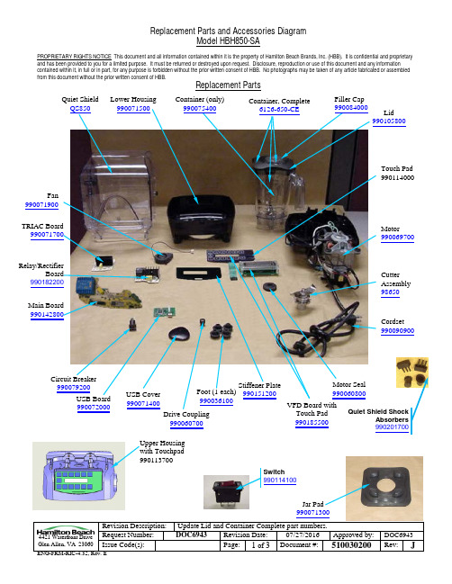
and has been provided to you for a limited purpose. It must be returned or destroyed upon request. Disclosure, reproduction or use of this document and any information contained within it, in full or in part, for any purpose is forbidden without the prior written consent of HBB. No photographs may be taken of any article fabricated or assembled from this document without the prior written consent of HBB.Revision Description:Update Lid and Container Complete part numbers.Replacement PartsQuiet Shield Lower Housing Container, Complete 990071300Container (only) Filler Capand has been provided to you for a limited purpose. It must be returned or destroyed upon request. Disclosure, reproduction or use of this document and any information contained within it, in full or in part, for any purpose is forbidden without the prior written consent of HBB. No photographs may be taken of any article fabricated or assembled from this document without the prior written consent of HBB.Revision Description:Update Lid and Container Complete part numbers.Post990078900990075300(Set is 2 pcs)990100500and has been provided to you for a limited purpose. It must be returned or destroyed upon request. Disclosure, reproduction or use of this document and any information contained within it, in full or in part, for any purpose is forbidden without the prior written consent of HBB. No photographs may be taken of any article fabricated or assembled from this document without the prior written consent of HBB.Revision Description:Update Lid and Container Complete part numbers.Accessories48oz Container Complete*6126-600Container WasherBCR100。
海尔冰箱使用说明书
目录产品介绍安全与警告提示 (2)产品特点 (3)处理旧冰箱的注意事项 (4)搬运和放置 (4)电器联接 (5)产品标准 (5)安装尺寸 (6)各部件名称 (7)使用使用前的准备 (8)温控器和灯装置 (8)开机和温度调节 (8)速冻 (9)冷藏室 (9)冷却能力 (9)冷冻室...........................9冷冻能力 (10)制作冰块 (10)冷冻食品的储存期 (10)清洁与维护除霜 (11)清洁 (12)节能 (12)其他事项 (12)非故障现象及特殊现象的分析与排除非故障现象 (13)特殊现象的分析与排除 (14)客户服务保修指南 (15)危险-不要将冰箱安放在潮湿和容易溅到水的地方。
危险-勿用湿手触摸冷冻室的食品或金属容器,否则,易因低温而造成冻伤。
警告-本产品为家用电冰箱,只适用于储藏食品,不能用于其它用途,如储藏血液及制品,药品,生物制品,化学物品和技术资料等。
警告-禁止损坏制冷管路。
管路中的制冷剂若溅入眼睛,会造成严重伤害。
万一发生此类事件,应立即清洗眼睛并到医院就诊。
警告-除了本公司推荐使用的类型外,不得在箱内使用电器。
警告-冰箱顶部不宜放置和使用微波炉、电饭锅、稳压器等电器装置,也不能在冰箱顶部放置重物及盛有液体的容器,以防掉下伤人或液体溢出导致漏电而引起的触电和火灾。
警告-易燃性气体泄漏时,应先关闭泄漏源的阀门,并设法排出室内空气。
切不可拔冰箱电源插座及操作冰箱,以防火灾发生。
警告-在冰箱的外壳或嵌入式结构中,必须保持通风顺畅并不得有阻碍物。
务必使用单独的、带可靠接地线的三芯电源插座。
冰箱应放置在电源插头容易接触的地方, 当发生事故时可以快速切断电源。
避免挤压、折叠、打结或损坏电源软线。
如果电源软线损坏,为避免危险,必须由制造厂或其维修部或类似的专职人员来更换。
更换电源线后冰箱才可通电使用,否则易造成触电甚至引发火灾。
拔电源插头时,不要直接拉拔电源软线,以防拉断。
电冰箱的工艺流程
电冰箱的工艺流程
《电冰箱的工艺流程》
电冰箱是家庭中常见的家电之一,它的生产工艺流程经过多个步骤,从原材料到成品需要经过严谨的生产工艺。
首先,电冰箱的生产需要使用各种原材料,如金属、塑料、绝缘材料等。
这些原材料需要经过检验和质量把关,确保符合生产要求。
接着,原材料需要经过加工和成型,这个过程包括金属冲压、塑料注塑等工艺,将原材料加工成零部件。
然后,各个零部件需要进行组装。
这个过程包括电机组装、冷冻系统组装、内外壳组装等工序,确保各个零部件正确安装在一起,构成完整的电冰箱结构。
在组装过程中,需要进行严格的质检,确保电冰箱的性能稳定和安全可靠。
接下来是涂装和包装。
电冰箱的外壳需要进行喷涂和表面处理,使其外观光滑、坚固并且美观。
而后,成品电冰箱需要进行包装,保护其不被损坏,方便运输和销售。
最后,成品电冰箱需要进行全面的检测和调试,确保其性能稳定、制冷效果好、使用安全,各项指标达到国家标准和产品要求。
经过严格的质量检验和调试,电冰箱才能交付使用者。
总的来说,电冰箱的生产工艺流程经过多个步骤,每个步骤都需要严格控制和管理,以确保成品的性能和质量。
只有经过严
谨的工艺流程,电冰箱才能成为家庭生活中的不可或缺的家电产品。
冰箱工艺流程

冰箱工艺流程冰箱是现代家庭中必不可少的电器之一,它的制造过程经历着多个工艺步骤。
下面我将介绍一下冰箱的工艺流程。
首先是冰箱的制造准备阶段。
在此阶段,首先需要进行产品的规划和设计工作。
设计师们根据市场需求和用户反馈,确定产品的外观造型、尺寸和功能配置。
然后,制定出生产计划,确定所需的材料、零部件和设备。
接下来是冰箱的材料准备阶段。
在这个阶段,需要准备冷藏室和冷冻室所需的铁皮板和塑料材料。
铁皮板经过模压加工,成型为冰箱的外壳。
塑料材料则通过注塑成型,制作出冰箱的内胆和把手等零部件。
然后是冰箱的组装阶段。
在这个阶段,首先是对冰箱外壳进行烤漆处理,使其表面光滑且具有防腐蚀功能。
之后,将外壳与内胆进行组合,焊接接头和安装密封胶条,以确保冰箱的密封性能。
接着,安装制冷系统,包括压缩机、冷凝器、蒸发器等核心零部件。
最后,安装控制面板、电路板和门盖等配件,并进行电气连接和测试。
接下来是冰箱的调试和质量检验阶段。
在此阶段,冰箱将接通电源,进行调试和测试,以确保其正常运转和各项功能的正常使用。
同时,还要进行质量检验,包括外观检查、功能检测和性能参数测试等,确保产品的质量符合标准。
最后是冰箱的包装和出厂阶段。
在这个阶段,冰箱将进行清洁和整理,确保外观无划痕和污垢。
然后,进行包装,使用适当的包装材料,保护产品免受运输过程中的损坏。
最后,冰箱将被送往仓库,并根据订单要求,安排发货和运输。
通过以上工艺流程,冰箱得以顺利制造出来。
这个过程中,涉及到多个关键操作和技术要求,需要工人们精确操作和严格控制,以确保产品的质量和性能。
冰箱工艺流程的不断改良和优化,也为消费者带来了更加智能和便捷的使用体验。
冰箱工艺流程

冰箱工艺流程
《冰箱工艺流程》
冰箱作为家庭中必不可少的电器,经过了许多工艺流程才能最终制成。
下面将为大家介绍一下冰箱的工艺流程。
首先,冰箱的制作从选材开始。
选择优质的材料是制作高品质冰箱的第一步。
冰箱的主要材料包括金属、塑料、玻璃等。
而制造高端冰箱时,更需要选用结实耐用的不锈钢材料。
接下来是冰箱的设计。
在设计阶段,工程师们根据市场需求和消费者的反馈,设计出符合人体工程学的冰箱结构。
他们还会根据冰箱的功能和外观设计出各种样式和规格的模具。
然后是生产工艺。
在生产线上,工人们根据预设的工艺流程,将各种零部件组装成完整的冰箱。
这个过程中需要用到各种专业的工具和设备,如焊接机、冲压机等。
最后是品质检验。
在冰箱制作完成后,需要进行严格的品质检验。
通过检验,确保冰箱的各项功能都正常运作,外观也没有瑕疵。
只有通过了品质检验的冰箱才能上市销售。
总的来说,冰箱的工艺流程是一个非常复杂且严谨的过程。
只有经过精心设计、精良制作和严格检验,才能生产出高质量的冰箱,让消费者放心使用。
海尔冰箱工艺手册

• 五、总装工艺
• 1、总装配是将各种冰箱材料及半成品用螺丝固定 及焊接的方式连结在一起,使之成为一台完整的 冰箱,总装配中的焊接、抽空灌注两工序是冰箱 制造中两个重要质量控制点,主要控制焊接质量 (焊漏焊堵)和制冷剂灌注量
• 二、发泡组份 • 多元醇:发泡的主组份之一,特点是易吸水注意
密封保存。 • 异氰酸酯:硬质聚氨酯泡沫的的主要原料之一,
常用的异氰酸酯为多苯基多次甲基多异氰酸酯,
即粗MDI或聚合MDI也叫PAPI,异氰酸酯易与 空气中的水分发生化学反应,应与空气隔 绝,在低温下易结晶,应保存在10---25℃ 环境中。
• 二电冰箱的门体由门面板、饰条、门衬板 和磁性门封条等组成其发泡工艺和用料成 分同箱体。
• 冰箱结构示意图
第三节发泡剂简介
• 一、发泡机理:聚氨酯泡沫用于冰箱生产 起到加强结构强度及隔热的作用,它是两 种液态组份即异氰酸酯和含有活泼氢的化 合物多元醇之间的化学反应产物.反应时, 异氰酸酯与多元醇混合物同时为发生的气 体所膨胀,经固化后得到泡沫塑料。
压缩机示意图
第三节防凝露加热管简介
• 防凝露加热管俗称除露管,其主要作用是 防止冷冻室门、顶板及门框附近的外表面 凝结露水。
• 防凝露加热管示意图(见图)
第四节冷凝器简介
• 冷凝器是使制冷剂气体放出热量变成液 体的热交换装置。
• 冷凝器的种类按冷却方式可分为水冷却 和空气冷却,其中空气冷却方式又分为 空气自然对流冷却和风扇强制对流冷却; 按形状结构可分为百叶窗式、丝管式和 内藏式冷凝器。目前我公司采用的主要
冰箱工艺流程
冰箱工艺流程
冰箱作为现代家庭中必不可少的家电产品,其制作工艺流程显得尤为重要。
下面将为大家介绍一下冰箱的工艺流程。
首先,冰箱的制作从选材开始。
冰箱的主要材料为金属、塑料和玻璃等,其中金属主要用于内外壳的制作,塑料用于内部隔板和抽屉的制作,玻璃则用于冰箱门的制作。
这些材料必须经过严格的筛选和检验,确保其质量符合要求。
接下来是冰箱的模具制作。
根据设计图纸,制作冰箱各个部件的模具。
模具的制作需要精密的加工工艺,确保冰箱的各个部件尺寸精准,符合设计要求。
随后是冰箱的加工制作。
首先是金属部件的冲压成型,通过冲压机将金属板材冲压成冰箱的内外壳等部件。
然后是塑料部件的注塑成型,将塑料料粒加热熔化后注入模具中,通过高压使其成型。
最后是玻璃部件的加工,将玻璃加热后弯曲成冰箱门的形状。
在各个部件制作完成后,需要进行表面处理。
金属部件经过喷涂或电镀等表面处理工艺,保护其表面不受腐蚀。
塑料部件经过喷
漆或丝印等工艺,美化其外观。
玻璃部件经过打磨和抛光等工艺,使其表面光滑。
最后是冰箱的组装。
将各个部件按照设计图纸进行组装,包括内外壳的组装、电器元件的安装、门的安装等。
组装完成后,需要进行严格的检测和调试,确保冰箱的各项功能正常。
通过以上工艺流程,一个高质量的冰箱就制作完成了。
这些工艺流程中的每一个环节都至关重要,任何一环节出现问题都可能影响整个产品的质量。
因此,在生产过程中,需要严格执行各项工艺要求,确保冰箱的质量和性能符合标准,为消费者提供优质的产品和服务。
冰箱基本工艺流程图

PE封顶胶带封顶
数量
更改单号
箱体发泡
签名
日期
设计 审核
第4页 共8页
工艺流程图--箱体发泡/初装
粘贴发泡标签、进 箱
箱体发泡
拆除温控工装
箱体检验
安装电容
装底脚和下铰链
压缩机底板装配
氮气检管堵
安装冷冻蒸发器,用 和捷环与洛克环连接 毛细管、蒸发器
拆除工艺螺钉并上 堵塞
清洁并去除泡料
焊口检漏
回收气体
翻转箱体
产品名称 UK/AG 系列冷藏冷冻箱 工艺段
总装
工艺流程图
文件编号
NJHS-B001GLT
贴冰箱条形码
拔管套、接高低压 管、装干燥过滤器
焊接
清洁管路、装 减震套
温控器组件予装
检漏
清洁箱体
安装温控器组件
抽真空 安装门上附件
灌注 封口
电气安全 性能检测
存储代号 旧底图总号
粘贴商标,能效 等级标识
底图总号 日期 签名
日期 签名
更改标记
数量
更改单号
签名
固定箱内附件
安装箱内附 件
安装台面框
预装箱内附件
装蒸发皿、整 管
包装
设计 审核
标准化
日期
ቤተ መጻሕፍቲ ባይዱ批准
第7页 共8页
GS-3
商检
工艺流程图
产品名称 UK/AG 系列冷藏冷冻箱 工艺段
包装
文件编号
NJHS-B001GLT
箱体外观
焊口
焊口处涂保护黑
固定机器室罩、盘
冰箱外观修理
出厂检查
GS-3
产品名称 UK/AG 系列冷藏冷冻箱 工艺段
海尔冰箱用户手册说明书
Seagate FireCuda 游戏扩展坞用户手册单击这里以访问本文档的最新在线版本。
您还将找到最新的内容,以及可扩展的说明、更轻松的导航和搜索功能。
. . . . . . . . . . . . . . . . . . . . . . . . . . . . . . . . . . . . . . . . . . . . . . . . . . . . . . . . . . . . . . . . . . . . . . . . . . . . . . . . . . . . . . . .. . . . . . . . . . . . . . . . . . . . . . . . . . . . . . . . . . . . . . . . . . . . . . . . . . . . . . . . . . . . . . . . . . . . . . . . . . . . . . . . . . . . . . . . . . . . . . . . . . . . . . . . . . . . . . . . . . . . . . . . . .. . . . . . . . . . . . . . . . . . . . . . . . . . . . . . . . . . . . . . . . . . . . . . . . . . . . . . . . . . . . . . . . . . . . . . . . . . . . . . . . . . . . . . . . . . . . . . . . . . . . . . . . . . . . . . . . . . . . . . . . . .. . . . . . . . . . . . . . . . . . . . . . . . . . . . . . . . . . . . . . . . . . . . . . . . . . . . . . . . . . . . . . . . . . . . . . . . . . . . . . . . . . . . . . . . . . . . . . . . . . . . . . . . . . . . . . . . . . . . . . . . . .. . . . . . . . . . . . . . . . . . . . . . . . . . . . . . . . . . . . . . . . . . . . . . . . . . . . . . . . . . . . . . . . . . . . . . . . . . . . . . . . . . . . . . . . . . . . . . . . . . . . . . . . . . . . . . . . . . . . . . . . . . . . . . . . . . . . . . . . . . . . . . . . . . . . . . . . . . . . . . . . . . . . . . . . . . . . . . . . . . . . . . . . . . . . . . . . . . . . . . . . . . . . . . . . . . . . .. . . . . . . . . . . . . . . . . . . . . . . . . . . . . . . . . . . . . . . . . . . . . . . . . . . . . . . . . . . . . . . . . . . . . . . . . . . . . . . . . . . . . . . . . . . . . . . . . . . . . . . . . . . . . . . . . . . . . . . . . .. . . . . . . . . . . . . . . . . . . . . . . . . . . . . . . . . . . . . . . . . . . . . . . . . . . . . . . . . . . . . . . . . . . . . . . . . . . . . . . . . . . . . . . . . . . . . . . . . . . . . . . . . . . . . . . . . . . . . . . . . .. . . . . . . . . . . . . . . . . . . . . . . . . . . . . . . . . . . . . . . . . . . . . . . . . . . . . . . . . . . . . . . . . . . . . . . . . . . . . . . . . . . . . . . . . . . . . . . . . . . . . . . . . . . . . . . . . . . . . . . . . . . . . . . . . . . . . . . . . . . . . . . . . . . . . . . . . . . . . . . . . . . . . . . . . . . . . . . . . . . . . . . . . . . . . . . . . . . . . . . . . . . . . . . . . . . . .. . . . . . . . . . . . . . . . . . . . . . . . . . . . . . . . . . . . . . . . . . . . . . . . . . . . . . . . . . . . . . . . . . . . . . . . . . . . . . . . . . . . . . . . . . . . . . . . . . . . . . . . . . . . . . . . . . . . . . . . . .. . . . . . . . . . . . . . . . . . . . . . . . . . . . . . . . . . . . . . . . . . . . . . . . . . . . . . . . . . . . . . . . . . . . . . . . . . . . . . . . . . . . . . . . . . . . . . . . . . . . . . . . . . . . . . . . . . . . . . . . . .. . . . . . . . . . . . . . . . . . . . . . . . . . . . . . . . . . . . . . . . . . . . . . . . . . . . . . . . . . . . . . . . . . . . . . . . . . . . . . . . . . . . . . . . . . . . . . . . . . . . . . . . . . . . . . . . . . . . . . . . . . . . . . . . . . . . . . . . . . . . . . . . . . . . . . . . . . . . . . . . . . . . . . . . . . . . . . . . . . . . . . . . . . . . . . . . . . . . . . . . . . . . . . . . . . . . .. . . . . . . . . . . . . . . . . . . . . . . . . . . . . . . . . . . . . . . . . . . . . . . . . . . . . . . . . . . . . . . . . . . . . . . . . . . . . . . . . . . . . . . . . . . . . . . . . . . . . . . . . . . . . . . . . . . . . . . . . .. . . . . . . . . . . . . . . . . . . . . . . . . . . . . . . . . . . . . . . . . . . . . . . . . . . . . . . . . . . . . . . . . . . . . . . . . . . . . . . . . . . . . . . . . . . . . . . . . . . . . . . . . . . . . . . . . . . . . . . . . . . . . . . . . . . . . . . . . . . . . . . . . . . . . . . . . . . . . . . . . . . . . . . . . . . . . . . . . . . . . . . . . . . . . . . . . . . . . . . . . . . . . . . . . . . . .. . . . . . . . . . . . . . . . . . . . . . . . . . . . . . . . . . . . . . . . . . . . . . . . . . . . . . . . . . . . . . . . . . . . . . . . . . . . . . . . . . . . . . . . . . . . . . . . . . . . . . . . . . . . . . . . . . . . . . . . . .. . . . . . . . . . . . . . . . . . . . . . . . . . . . . . . . . . . . . . . . . . . . . . . . . . . . . . . . . . . . . . . . . . . . . . . . . . . . . . . . . . . . . . . . . . . Contents1欢迎使用包装内容最低系统要求视图2使用入门连接电源连接到计算机设置 FireCuda 游戏扩展坞3使用 Toolkit 自定义 RGB 以及更多内容自定义 RGB 颜色设置启动备份计划(仅限 Windows )设置镜像文件夹4格式化和分区(可选)选择文件系统格式格式化说明5从您的计算机安全移除设备Windows Mac 6常见问题解答. . . . . . . . . . . . . . . . . . . . . . . . . . . . . . . . . . . . . . . . . . . . . . . . . . . . . . . . . . . . . . . . . . . . . . . . . . . . . . . . . . . . . . . . . . . . . . . . . . . . . . . . . . . . . . . . . . 端口. . . . . . . . . . . . . . . . . . . . . . . . . . . . . . . . . . . . . . . . . . . . . . . . . . . . . . . . . . . . . . . . . . . . . . . . . . . . . . . . . . . . . . . . . . . . . . . . . . . . . . . . . . . . . . . . . . 操作系统. . . . . . . . . . . . . . . . . . . . . . . . . . . . . . . . . . . . . . . . . . . . . . . . . . . . . . . . . . . . . . . . . . . . . . . . . . . . . . . . . . . . . . . . . . . . . . . . . . . . . . . . . . . . . . . . . . 最低可用磁盘空间:. . . . . . . . . . . . . . . . . . . . . . . . . . . . . . . . . . . . . . . . . . . . . . . . . . . . . . . . . . . . . . . . . . . . . . . . . . . . . . . . . . . . . . . . . . . . . . . . . . . . . . . . . . . . . . . . . . 前面. . . . . . . . . . . . . . . . . . . . . . . . . . . . . . . . . . . . . . . . . . . . . . . . . . . . . . . . . . . . . . . . . . . . . . . . . . . . . . . . . . . . . . . . . . . . . . . . . . . . . . . . . . . . . . . . . . 上一步. . . . . . . . . . . . . . . . . . . . . . . . . . . . . . . . . . . . . . . . . . . . . . . . . . . . . . . . . . . . . . . . . . . . . . . . . . . . . . . . . . . . . . . . . . . . . . . . . . . . . . . . . . . . . . . . . . 在这里开始. . . . . . . . . . . . . . . . . . . . . . . . . . . . . . . . . . . . . . . . . . . . . . . . . . . . . . . . . . . . . . . . . . . . . . . . . . . . . . . . . . . . . . . . . . . . . . . . . . . . . . . . . . . . . . . . . . 注册您的设备. . . . . . . . . . . . . . . . . . . . . . . . . . . . . . . . . . . . . . . . . . . . . . . . . . . . . . . . . . . . . . . . . . . . . . . . . . . . . . . . . . . . . . . . . . . . . . . . . . . . . . . . . . . . . . . . . . 下载 Toolkit . . . . . . . . . . . . . . . . . . . . . . . . . . . . . . . . . . . . . . . . . . . . . . . . . . . . . . . . . . . . . . . . . . . . . . . . . . . . . . . . . . . . . . . . . . . . . . . . . . . . . . . . . . . . . . . . . . 安装 Toolkit . . . . . . . . . . . . . . . . . . . . . . . . . . . . . . . . . . . . . . . . . . . . . . . . . . . . . . . . . . . . . . . . . . . . . . . . . . . . . . . . . . . . . . . . . . . . . . . . . . . . . . . . . . . . . . . . . . 同时兼容 Windows 和 Mac . . . . . . . . . . . . . . . . . . . . . . . . . . . . . . . . . . . . . . . . . . . . . . . . . . . . . . . . . . . . . . . . . . . . . . . . . . . . . . . . . . . . . . . . . . . . . . . . . . . . . . . . . . . . . . . . . . 针对 Windows 优化性能. . . . . . . . . . . . . . . . . . . . . . . . . . . . . . . . . . . . . . . . . . . . . . . . . . . . . . . . . . . . . . . . . . . . . . . . . . . . . . . . . . . . . . . . . . . . . . . . . . . . . . . . . . . . . . . . . . 针对 macOS 优化性能. . . . . . . . . . . . . . . . . . . . . . . . . . . . . . . . . . . . . . . . . . . . . . . . . . . . . . . . . . . . . . . . . . . . . . . . . . . . . . . . . . . . . . . . . . . . . . . . . . . . . . . . . . . . . . . . . . 了解更多. . . . . . . . . . . . . . . . . . . . . . . . . . . . . . . . . . . . . . . . . . . . . . . . . . . . . . . . . . . . . . . . . . . . . . . . . . . . . . . . . . . . . . . . . . . . . . . . . . . . . . . . . . . . . . . . . . 通过 Finder 窗口退出. . . . . . . . . . . . . . . . . . . . . . . . . . . . . . . . . . . . . . . . . . . . . . . . . . . . . . . . . . . . . . . . . . . . . . . . . . . . . . . . . . . . . . . . . . . . . . . . . . . . . . . . . . . . . . . . . . 通过桌面退出444444445667889991111111112121212121313141414141415. . . . . . . . . . . . . . . . . . . . . . . . . . . . . . . . . . . . . . . . . . . . . . . . . . . . . . . . . . . . . . . . . . . . . . . . . . . . . . . . . . . . . . . . . . . . . . . . . . . . . . . . . . . . . . . . . . . . . . . . . . . . . . . . . . . . . . . . . . . . . . . . . . . . . . . . . . . . . . . . . . . . . . . . . . . . . . . . . . . . . . . . . . . . . . . . . . . . . . . . . . . . . . . . . . . . . . . . . . . . . . . . . . . . . . . . . . . . . .. . . . . . . . . . . . . . . . . . . . . . . . . . . . . . . . . . . . . . . . . . . . . . . . . . . . . . . . . . . . . . . . . . . . . . . . . . . . . . . . . . . . . . . . . . . . . . . . . . . . . . . . . . . . . . . . . . . . . . . . . .. . . . . . . . . . . . . . . . . . . . . . . . . . . . . . . . . . . . . . . . . . . . . . . . . . . . . . . . . . . . . . . . . . . . . . . . . . . . . . . . . . . . . . . . . . . . . . . . . . . . . . . . . . . . . . . . . . . . . . . . . . . . . . . . . . . . . . . . . . . . . . . . . . . . . . . . . . . . . . . . . . . . . . . . . . . . . . . . . . . . . . . . . . . . . . . . . . . . . . . . . . . . . . . . . . . . .. . . . . . . . . . . . . . . . . . . . . . . . . . . . . . . . . . . . . . . . . . . . . . . . . . . . . . . . . . . . . . . . . . . . . . . . . . . . . . . . . . . . . . . . . . . . . . . . . . . . . . . . . . . . . . . . . . . . . . . . . .所有用户Windows Mac 7Regulatory Compliance China RoHS Taiwan RoHS . . . . . . . . . . . . . . . . . . . . . . . . . . . . . . . . . . . . . . . . . . . . . . . . . . . . . . . . . . . . . . . . . . . . . . . . . . . . . . . . . . . . . . . . . . . . . . . . . . . . . . . . . . . . . . . . . . 问题:我的文件传输速度很慢. . . . . . . . . . . . . . . . . . . . . . . . . . . . . . . . . . . . . . . . . . . . . . . . . . . . . . . . . . . . . . . . . . . . . . . . . . . . . . . . . . . . . . . . . . . . . . . . . . . . . . . . . . . . . . . . . . 问题:我的计算机只有 USB-C 端口. . . . . . . . . . . . . . . . . . . . . . . . . . . . . . . . . . . . . . . . . . . . . . . . . . . . . . . . . . . . . . . . . . . . . . . . . . . . . . . . . . . . . . . . . . . . . . . . . . . . . . . . . . . . . . . . . . 问题:我必须对 USB 设备使用 USB 集线器. . . . . . . . . . . . . . . . . . . . . . . . . . . . . . . . . . . . . . . . . . . . . . . . . . . . . . . . . . . . . . . . . . . . . . . . . . . . . . . . . . . . . . . . . . . . . . . . . . . . . . . . . . . . . . . . . . 问题:提供的 USB 电缆太短. . . . . . . . . . . . . . . . . . . . . . . . . . . . . . . . . . . . . . . . . . . . . . . . . . . . . . . . . . . . . . . . . . . . . . . . . . . . . . . . . . . . . . . . . . . . . . . . . . . . . . . . . . . . . . . . . . 问题:我收到了文件传输错误消息. . . . . . . . . . . . . . . . . . . . . . . . . . . . . . . . . . . . . . . . . . . . . . . . . . . . . . . . . . . . . . . . . . . . . . . . . . . . . . . . . . . . . . . . . . . . . . . . . . . . . . . . . . . . . . . . . . 问题:计算机中未显示硬盘图标. . . . . . . . . . . . . . . . . . . . . . . . . . . . . . . . . . . . . . . . . . . . . . . . . . . . . . . . . . . . . . . . . . . . . . . . . . . . . . . . . . . . . . . . . . . . . . . . . . . . . . . . . . . . . . . . . . 问题:我的桌面上未显示硬盘图标15151515161616161717181818欢迎使用包装内容®®Seagate FireCuda游戏扩展坞电源适配器USB 3.0 电缆(USB micro-B 转 USB-A)快速入门指南最低系统要求端口您可以使用 USB-A(USB 3.0 或 USB 2.0)端口将 Seagate 设备连接到计算机。
海尔电器维修技术手册说明书

FOR SERVICE TECHNICIAN’S USE ONL YFOR SERVICE TECHNICIAN’S USE ONL YFOR SERVICE TECHNICIAN’S USE ONL Y324FOR SERVICE TECHNICIAN’S USE ONL YT ech SheetDo not discardFOR SERVICE TECHNICIAN’S USE ONLYPRECAUTIONS TO BE OBSERVED BEFORE AND DURING SERVICING TO AVOID POSSIBLE EXPOSURE TO EXCESSIVE MICROWAVE ENERGYa. Do not operate or allow the oven to be operated with the dooropen.b. Make the following safety checks on all ovens to be servicedbefore activating the magnetron or other microwave source, and make repairs as necessary:1. Interlock Operation 2. Proper Door Closing3. Seal and Sealing Surfaces (Arcing, Wear and Other Damage)4. Damage to or Loosening of Hinges and Latches5. Evidence of Dropping or Abusec. Before turning on microwave power for any service test orinspection within the microwave generating compartments, check the magnetron, wave guide or transmission line, and cavity for proper alignment, integrity and connections.d. Any defective or misadjusted components in the interlock,monitor, door seal, and microwave generation and transmission systems shall be repaired, replaced, or adjusted by procedures described in this manual before the oven is released to the owner.e. A microwave leakage check to verify compliance with the FederalPerformance Standard should be performed on each oven prior to release to the owner.f. Do not attempt to operate the oven if the door glass is broken.FAILURE CODE INDICATIONSNOTE: Many of the problems listed in the chart below may be solved by power cycling: Unplug microwave oven or disconnect power. After 1 minute, plug in microwave oven or reconnect power.Display Likely Failure Condition Recommended Repair Procedure“Enter clock”Power failureAfter a power failure, “Enter clock” will be flashing. Press CANCEL to end this indication. The colon (:) will appear when in Standby mode.F1E4Microwave ACU failure 1. Unplug microwave oven or disconnect power.2. Replace ACU.3. Replace all parts and panels before operating.4. Plug in microwave oven or reconnect power.F2E1Stuck key failure1. Unplug microwave oven or disconnect power.2. Replace touch panel.3. Replace all parts and panels before operating.4. Plug in microwave oven or reconnect power.F4E4Humidity sensor error 1. Enter the Diagnostics mode (press CANCEL - CANCEL- START), and then press COOK TIME to display the humidity sensor reading. If display does not show “3789,” continue to Step 2. Press COOK POWER to display the RH sensor NTC reading. If display does not show “026,” continue to Step 2.2. Unplug microwave oven or disconnect power.3. Connect a new humidity sensor ACU to cable.4. Replace all parts and panels before operating.5. Plug in microwave oven or reconnect power.6. Enter the Diagnostics mode (press CANCEL - CANCEL - START), then press COOKTIME, and then press COOK POWER to see if failure code reappears.NOTE: There may be a delay (approximately 1 minute, 20 seconds) before the F4E4 failure code is displayed.7. If the F4E4 failure code reappears, unplug microwaveoven or disconnect power.8. Replace ACU.9. Replace all parts and panels before operating.10. Plug in microwave oven or reconnect power.F8E5Exhaust air templatedetection failure1. Enter the Diagnostics mode (pressCANCEL - CANCEL - START), and then press OPTIONS/CLOCK to display the exhaust air temperature sensor reading. Verify the sensor temperature reading is at room temperature (typically 50ºF to 90ºF [10ºC to 32ºC]) and verify failure code. If failure code matches complaint, continue to Step 2.2. Unplug microwave oven or disconnect power.3. Disconnect sensor from ACU.4. Measure sensor resistance between connector pinsand confirm reading is between 9.5 kΩ and 10.5 kΩ at room temperature. If measurement is not correct, or if a short or open circuit is found, replace sensor.5. Replace all parts and panels before operating.6. Plug in microwave oven or reconnect power.7. Enter the Diagnostics mode (pressCANCEL - CANCEL - START), and then pressOPTIONS/CLOCK to display the cavity temperature sensor reading. Verify the sensor temperature reading. If it is still not correct, replace ACU.8. If failure does not reappear, stop.PRIMARY , MONITOR, SECONDARY , AND DOOR INTERLOCK SWITCH CHECKOUT PROCEDURESIMPORTANT: Before checking the interlock switches, unplug microwave oven or disconnect power. Be sure to disconnect all of the wires at the switch being tested before making any continuity readings.NOTE: The Primary Interlock switch, Monitor Interlock switch, Secondary Interlock Switch, and Door Interlock Switch are mounted in the door lockswitch cradle. All the Interlock Switches can be identified by the wire colors that are connected to the terminals of the switches. See the chart below for wire color designation.SwitchCheck ByDoor OpenDoor ClosedPrimary Interlock1. Unplug microwave oven or disconnect power.2. Disconnect the wires at the Primary Interlock Switch.3. Check from the common terminal (black/brown wires) to the normally open terminal(black/white wires).4. Reconnect wires to switch.-+Monitor Interlock 1. Unplug microwave oven or disconnect power.2. Disconnect the wires at the Monitor Interlock Switch.3. Check from the common terminal (white wire) to the normally closed terminal(blue/white wires).4. Reconnect wires to switch.+-Secondary Interlock 1. Unplug microwave oven or disconnect power.2. Disconnect the wires at the Secondary Interlock Switch.3. Check from the common terminal (white/blue wires) to the normally open terminal(blue/blue wires).4. Reconnect wires to switch-+Door Interlock 1. Unplug microwave oven or disconnect power.2. Disconnect the wires at the Door Interlock Switch.3. Check from the common terminal (blue wire) to the normally closed terminal(orange wire).4. Reconnect wires to switch.+-(+) Continuity (-) No ContinuityM W O v e n R u n n i n g —A C V R e a d i n g sP i n N a m eW i r e C o l o rP o w e r O n , D o o rC l o s e dP o w e r O n , D o o r O p e nH o o d F a n M o t o r —H i g hH o o d F a n M o t o r —H i g h , D o o r O p e nH o o d F a n M o t o r —M e d -H i g hH o o d F a n M o t o r —M e d -H i g h , D o o r O p e nH o o d F a n M o t o r —M e d i u mH o o d F a n M o t o r —M e d i u m , D o o r O p e nH o o d F a nM o t o r —L o wH o o d F a n M o t o r —L o w , D o o r O p e nH o o d L i g h t —H ig hH o od L i g h t —H i g h , D o o r O pe nH o o d L i g h t —L o wH o o d L i g h t —L o w , D o o r O p e nM W O v e n S t a r t P1-1 (L)Brown 120120120120120120120120120120120120120120120P1-3 (N)White 00 0000000000000P2-3 (NFS)White 0120012001200120012001200120 3.6P2-2 (Door)Orange 012001200120012001200120012049P2-1 (N)Green 000000000000000P4-4 (HF)White 01200120012001200120012000120P4-5 (TTM)Red 0120012001200120012001200120120P4-1 (HL)Yellow 00000000001201206767 2.4P4-2 (HF-R)Gray 00120120120120585877770000 3.6P4-3 (HF-Hi)Black001201206868585839390000 3.7P4-6 (CL)Green151151120120555577773.7CONNECTORS ON ACUTOUCH P ANELT ouch Panel and ACU T estThe microwave hood combination is provided with a self-diagnostic routine that can be accessed through the touch keypad.T o initiate this routine:1. Plug in microwave oven or reconnect power, and press CANCEL tostandby (“:”).2. Close door, then press CANCEL - CANCEL - START within3 seconds.3. All display segments will be lit to indicate the Test mode has beenentered.NOTE: If CANCEL is pressed during this diagnostic routine, you will exit the Test mode.ACU21P41 2 3 4 5 6Relay 4903P11 3L N.P91 2P111 2 3 4P6 3 2 1P21 2 3P3 14 13 12 11 10 9 8 7 6 5 4 3 2 1P71234567891011Relay 490321NOTE: There are purposely emptyterminals between each of the numbered terminals on P1 connector.W11268419ANOTE: These diagrams are not intended to show a complete circuit; they represent the position of switches during “DOOR OPEN” or “DOOR CLOSED” (continuity checks only).NOTE: Interlock, Monitor switches and Door interlock switch cannot be adjusted and all these switches should be replaced if any one of them is found to be defective. After replacing interlock/monitor switches, reconnect wires to switch and check for continuity. Safety interlocks and monitor switches will actuate within 2 mm.Door ClosedDoor OpenNOT HEATING TROUBLESHOOTING INSTRUCTIONIMPORTANT: High-voltage is present at the magnetron and high-voltage capacitor terminals. Avoid direct contact when power is connected to these components to avoid serious injury or possible death. Always be sure that the high-voltage capacitor is discharged before accessing any of these components.For a no-heat condition, refer to the following step-by-step instructions:1. Unplug microwave oven or disconnect power.2. Discharge the high-voltage capacitor.3. Disconnect the high-voltage transformer primary windings.4. Attach the voltmeter leads to the high-voltage transformer primaryinput wires.5. Plug in microwave oven or reconnect power.6. Close door and program the microwave oven to operate for30 seconds.7. Press START.8. Check the input voltage at the high-voltage transformer primary inputwires. If the voltage is not close to the rating voltage 120 +/-15 VAC, unplug microwave oven or disconnect power. Check the circuitry as follows:■Measure resistance of the fuse, microswitches and thermostats. Replace any failed components. (Refer to the wiring diagram.)■Check for loose terminals. (Refer to the wiring diagram.) Check all of the terminals on the main route from the power supply to the high-voltage transformer.■Check for loose or failed connectors on the ACU (P1, P2, P4). Ifthese check out OK, plug in microwave oven or reconnect power. ■Check for ACU failure. Refer to the “ACU Pin Voltage Matrix” section.9. If the input voltage at the high-voltage transformer primary inputwires is close to the rating voltage 120 +/-15 VAC, unplug microwave oven or disconnect power.10. Check the power supply components. Refer to the “ComponentTests” section.■High-voltage transformer ■High-voltage capacitor■High-voltage diode11. If the power supply components check out OK, check the connectionbetween the magnetron and the high-voltage transformer.12. If all of the components check out OK, replace the magnetron.13. Reconnect the high-voltage transformer primary windings.ACU PIN VOLTAGE MATRIXCheck for proper voltage by completing the following steps:1. Unplug microwave oven or disconnect power.2. Connect voltage measurement equipment to the terminals listedbelow. (P1-3 and P2-3 are neutral.) 3. Plug in microwave oven or reconnect power, and confirm voltagereading.4. Unplug microwave oven or disconnect power.NOTE: For 50 V and over, the tolerance is +/-15 V . For 0 V , the tolerance is +/-3 V .AbbreviationsHL – Hood LightN – NeutralCL – Cavity LightHF – Hood FanL – Line VoltageTT – Turntable MotorNFS – Neutral for SwitchNOTE: When checking voltage readings on ACU, connect the grounding test lead of voltmeter to P1-3, P2-1. Use the positive test lead to probe connectors designated below.Door Interlock SwitchSecondary Interlock Switch(NO)Interlock SwitchDoor Interlock SwitchMW Oven Plugged In—Sitting Idle—ACV ReadingsFOR SERVICE TECHNICIAN’S USE ONL Y FOR SERVICE TECHNICIAN’S USE ONL YFOR SERVICE TECHNICIAN’S USE ONL Y FOR SERVICE TECHNICIAN’S USE ONL Y 57608/18FOR SERVICE TECHNICIAN’S USE ONLYW11268419A©2018 All rights reserved.Components Test/ResultsH.V. Transformer 1. Unplug microwave oven or disconnect power.2. Remove wire leads.3. Measure resistance:■Primary winding: Less than 0.5 ohm (approximate)■Secondary winding: 120 ohms (approximate)■Filament winding: 0 ohms■Primary winding to grounding: Normal: Infinite■Filament winding to grounding: Normal: InfiniteMagnetron 1. Unplug microwave oven or disconnect power.2. Remove wire leads.3. Measure resistance:■Filament terminal: Normal: Less than 1 ohm■Filament to chassis: Normal: InfiniteH.V. Capacitor 1. Unplug microwave oven or disconnect power.2. Remove wire leads.3. Measure resistance:■Terminal to terminal: Normal: Momentarily indicates several ohms and then gradually returns toinfinite.■Terminal to case: Normal: InfiniteH.V. Diode NOTE: Some inexpensive meters may indicate infinite resistance in both directions.1. Unplug microwave oven or disconnect power.2. Measure resistance:■Forward: Normal: Continuity■Reverse: Normal: InfiniteTurntable Motor 1. Unplug microwave oven or disconnect power.2. Remove wire leads.3. Measure resistance:■Normal: 2.4k to 3.2k ohms (approximate)Motor Capacitor 1. Unplug microwave oven or disconnect power.2. Remove wire leads.3. Measure motor capacitor:■Normal: Momentarily 0 ohms, then goes to infinite1. Unplug microwave oven or disconnect power.2. Remove the 4-pin connector from the cable.3. Measure resistance across pins 1 and 2.■Normal: 10k ohms +/-5% at 77°F (25°C)4. Measure capacity value across pins 3 and 4.■Normal: 180pF +/-5% at 55% RHHood Exhaust Fan Motor 1. Unplug microwave oven or disconnect power.2. Remove wire leads.3. Measure resistance:■High Speed—Normal: Red (RD) and Blue (BU) wires: 70 to 100 ohms (approximate); Blue (BU) andBlack (BK) wires: 30 to 60 ohms (approximate)■Low Speed—Normal: Red (RD) and Blue (BU) wires: 70 to 100 ohms (approximate); Blue (BU) andWhite (WH) wires: 50 to 80 ohms (approximate)HF NTC Thermistor 1. If “NTC SHORT, CALL FOR SERVICE” or “NTC OPEN, CALL FOR SERVICE” scrolls on display, unplugmicrowave oven or disconnect power.2. Measure resistance:■Normal: 10k ohms +/-5% at 77ºF (25ºC)Power Resistor 1. Unplug microwave oven or disconnect power.2. Remove wire leads.3. Measure resistance:■Normal: 65 ohms/65 WPrimaryFilament(orange/red wires)Secondary (whitewire - ground totransformer case)23Components Test/ResultsCooling Fan Motor 1. Unplug microwave oven or disconnect power.2. Remove wire leads.3. Measure resistance:■Normal: 40 to 60 ohms (approximate)AC Line Filter Board 1. Unplug microwave oven or disconnect power.2. Remove wire leads.3. Measure resistance:■Normal: L-IN to L-OUT (coil): Less than 1 ohm; N-IN to N-OUT (coil): Less than 1 ohmThermostats NOTE: Refer to “Parts Layout” for opening and closing temperatures.1. Unplug microwave oven or disconnect power.2. Remove wire leads.3. Measure continuity:■Normal: ContinuitySCHEMATIC DIAGRAMCavity ThermostatMagnetron ThermostatCavityzH6V521/V21CAKey T ables for T est ModeKey Name Function Display BuzzerPopcorn-key 30 1 beepPotato orBaked Potato-key 31 1 beepVegetable-key 2E 1 beepFrozen Entrée-key 33 1 beepSteam Simmeror Steam Cook-key 2D 1 beepWarm Hold-key 06 1 beepReheat-key 24 1 beepDefrost-key 25 1 beepSoften/Melt-key 29 1 beepCook Time Humidity sensorcheckValue between2000 and 60001 beepCook Power RH NTC sensorcheckValue between10 and 401 beepCook key 07 1 beepTimer Set/Off-key 05 1 beepOptions/Clock HF NTC Thermistor XXX 1 beepStart or Software/Geeversion check*xx.xx.xx 1 beepAdd 30 Sec or +30Sec key 20 1 beepDinner Plate-key 32 1 beepBeverage-key 34 1 beepPizza-key 35 1 beep* Continuously pressing START or will respectively display SW Versionand Gee Version for each press.Key Name Function Display Buzzer1Cavity Light andCooling Fan OnCL 1 beep2Cavity Light, CoolingFan and Turntable OnCL TT 1 beep3-key 36 1 beep4-key 14 1 beep5-key 15 1 beep6Hood (Cooktop) LightOn (High)HL HIGH 1 beep7Hood (Cooktop) LightOn (Low)HL LOW 1 beep8Vent Fan On (HighSpeed)HF HIGH 1 beep9Vent Fan On (LowSpeed)HF LOW 1 beep0Microwave Oven(1000 W), CL, TT andCF On for 10 SecondsMW 1 beepLight or -key 03 1 beepTurntable -key 09 1 beepPOWER OUTPUT MEASUREMENTThe power output of the magnetron can be measured using the following“Voltage Measurement” and “Output Test” sections. Before you performthe test:■Make sure that the oven cavity is cool and clean.■Check the line voltage at the wall outlet while microwave oven isoperating. See the “Voltage Measurement at Power Source” section.T ools Needed■2-cup measuring cup■Thermometer■Voltmeter/ohmmeterVoltage Measurement at Power Source1. Fill the measuring cup with 2 cups (500 mL) of tap water.2. Place in the center of the microwave oven cavity.3. Operate the microwave oven on High speed for 1 minute.4. While the microwave oven is operating, measure the line voltage atthe power source. See “Measure Voltage” illustration.5. Verify the voltage is constant during microwave oven operation. Ifvoltage drops below 108V, contact a qualified electrician to checkyour electrical supply.6. Make note of the voltage while the microwave oven is running andproceed to the output test.Measure VoltageOutput T est1. Fill the measuring cup with 2 cups (500 mL) of 70ºF (21ºC) tap water.2. Stir the water with the thermometer to ensure uniform temperature.Add warm or cool water to bring the water to the correct temperature.3. Place the measuring cup in the center of the microwave oven cavity.4. Operate the microwave oven on High speed for 1 minute.5. Remove the measuring cup and stir the water with the thermometerfor about 20 seconds.6. Record the temperature of the water.7. Refer to the model serial tag on the microwave oven to acquirewattage output rating of the microwave oven.8. Using the following chart, determine if the output of the microwaveoven is within the range listed based on the line voltage and wattagerating of the microwave oven.Water Temperature for Line Voltage and Wattage RatingVoltage700 W1000 W1200 W120 V96ºF to 102ºF(36ºC to 39ºC)110ºF to 116ºF(43ºC to 47ºC)124ºF to 130ºF(51ºC to 54ºC)108 V91ºF to 97ºF(33ºC to 36ºC)101ºF to 107ºF(38ºC to 42ºC)111ºF to 117ºF(44ºC to 47ºC)COMPONENT TESTSAA. House power supply wall outletB. Voltmeter/Ohmmeter test leadsC. Microwave oven plugP ARTS LA YOUT (NOT TO SCALE)A. Line fuse (20 amp)B. AC line filter boardC. Hood fan motor assemblyD. Cavity lightE. Cavity light holderF. MagnetronG. Magnetron thermostat—opens at 257ºF (125ºC), closesat 185ºF (85ºC)H. Power resistorI. H.V. capacitorJ. H.V. diodeK. H.V. transformerL. Motor capacitorM. Cooling fan motorN. HF NTC thermistorO. ACUP. Touch panelQ. Secondary interlock switchR. Door interlock switchS. Monitor interlock switchT. Primary interlock switchU. Turntable motorV. Hood (cooktop) lightW. Hood (cooktop) light holderX. Cavity thermostat—opens at 257°F (125°C), non-resettableY. Humidity sensor ACUIMPORTANT:■Unplug microwave oven or disconnect power.■Discharge the high-voltage capacitor and remove thelead wires from the primary winding of the high-voltagetransformer before conducting any of the following tests.■Remove the lead wires from the related component beforeconducting any of the following tests.■All operational checks using microwave energy must be donewith the microwave oven loaded with a minimum of 8 oz(250 mL) of water in a microwave-safe container.■Conduct a microwave energy test after performing any testsor repairs to the microwave oven.■Check that all wire leads are in the correct positions beforeoperating the microwave oven.■Grasp wire connectors when removing the wire leads frommicrowave oven parts.■All testing must be done with an ohmmeter having asensitivity of 20,000 ohms per volt DC or greater andpowered by at least a 9 V battery.。
电冰箱生产工艺流程

电冰箱生产工艺流程
《电冰箱生产工艺流程》
电冰箱是现代家庭不可或缺的家电之一,它可以将食物保持新鲜并延长其保存时间。
电冰箱的生产工艺流程包括多个关键步骤,其中每个步骤都需要精心设计和严格执行,以确保最终产品的质量和性能。
首先,电冰箱的生产从原材料的采购开始。
生产商需要向供应商购买钢板、压缩机、保温材料、塑料件等各种原材料。
这些原材料的质量和性能直接影响到最终产品的质量,因此供应商的选择至关重要。
其次,原材料的加工和制造是电冰箱生产工艺的核心环节。
钢板需要经过模具加工、焊接、折弯等一系列工序,最终形成冰箱的机身。
压缩机需要安装在机身内部,并与管路连接。
保温材料需要填充在机身的壁板之间,以保持冷藏室的温度。
塑料件则需要制作成冰箱的门把手、储物格等配件。
接下来是电冰箱的组装和调试。
组装工人需要按照工艺流程的要求,将机身、门体、压缩机、控制面板等组件装配在一起。
在组装完成后,需要进行空调系统的抽真空和充注制冷剂,以确保冰箱的制冷效果。
同时还需要进行电气系统的调试,以确保冰箱的各个功能正常运行。
最后,是电冰箱的质检和包装。
生产商需要对成品进行严格的质量检查,确保冰箱的各项性能符合标准。
通过包装,将成品
包装起来,保护其不受损坏,然后发往仓库或者零售商处。
这个环节也是整个生产工艺流程中至关重要的一环,包装的质量直接关系到产品在运输和销售过程中的安全性。
总的来说,电冰箱生产工艺是一个复杂的系统工程,需要各个部门的密切配合和严格执行。
只有在每个环节都做到精益求精,才能生产出高质量、高性能的电冰箱产品。
- 1、下载文档前请自行甄别文档内容的完整性,平台不提供额外的编辑、内容补充、找答案等附加服务。
- 2、"仅部分预览"的文档,不可在线预览部分如存在完整性等问题,可反馈申请退款(可完整预览的文档不适用该条件!)。
- 3、如文档侵犯您的权益,请联系客服反馈,我们会尽快为您处理(人工客服工作时间:9:00-18:30)。
压缩机示意图
第三节防凝露加热管简介
• 二、发泡组份 • 多元醇:发泡的主组份之一,特点是易吸水注意
密封保存。 • 异氰酸酯:硬质聚氨酯泡沫的的主要原料之一,
常用的异氰酸酯为多苯基多次甲基多异氰酸酯,
即粗MDI或聚合MDI也叫PAPI,异氰酸酯易与 空气中的水分发生化学反应,应与空气隔 绝,在低温下易结晶,应保存在10---25℃ 环境中。
• 按使用气候类型分类:亚温带(SN )、温带(N )、 亚热带(ST)和热带(T )。
• 按冷冻室温度及其所能达到的温度分类:1星、2 星、3星、4星共四个星级。
• 按制冷方式分类:压缩式、吸收式和半导体式电 冰箱(电机压缩式按冷却方式又可分为直冷式和 风冷式两种)。
• 三、以BCD-188AL为例说明冰箱型号表示方法 其中:B是指家用电冰箱
• 5、组分温度: 环戊烷:22±2℃ • 6、 模具温度:40--50℃ • 7、炉温:40--70℃ • 8、环境温度:≥20℃
第三章家用电冰箱的制冷系统
• 第一节电冰箱制冷系统结构特点 • 第二节压缩机简介 • 第三节防凝露加热管简介 • 第四节冷凝器简介 • 第五节干燥过滤器简介 • 第六节毛细管简介 • 第七节蒸发器简介
蒸发器。 • 蒸发:经过毛细管节流的制冷剂在蒸发器内膨胀,汽化吸
热,变成低压低温蒸气,又被压缩机吸入。
三、电冰箱制冷循环图示意图
左冷凝器
右
冷
除露管
凝
器
过滤器
藏蒸发 器
毛细管
回气管
压缩机
第二节常用制冷剂
• 一、制冷剂是制冷系统中实现制冷循环的工作介 质,也称为制冷工质,制冷剂在制冷系统中循环 流动的过程中发生的状态变化是物理变化,起着 吸热和放热的作用,并在系统中长期循环使用。
第二章家用电冰箱的结构特点
• 第一节家用电冰箱分类 • 第二节箱体 • 第三节发泡剂简介
第一节家用电冰箱分类
一、家用电冰箱的组成 • 家用电冰箱的外形多种多样,但主要结构
大致相同,一般均由箱体、制冷系统、电 气系统等几个部分组成。
• 二、家用电冰箱分类
• 按箱门型式分类:单门冰箱、双门冰箱及多门冰 箱。
冰箱工艺 培训手册
第一章制冷技术基础知识 第二章家用电冰箱的结构特点 第三章家用电冰箱的制冷系统 第四章家用电冰箱的电气系统 第五章冰箱工艺 第六章冰箱管理体系认证
第一章制冷技术基础知识
• 第一节制冷原理 • 第二节常用制冷剂
第一节制冷原理
一、制冷原理 • 从低于环境温度的物体中吸取热量,并将其转移给环
• 二电冰箱的门体由门面板、饰条、门衬板 和磁性门封条等组成其发泡工艺和用料成 分同箱体。
• 冰箱结构示意图
第三节发泡剂简介
• 一、发泡机理:聚氨酯泡沫用于冰箱生产 起到加强结构强度及隔热的作用,它是两 种液态组份即异氰酸酯和含有活泼氢的化 合物多元醇之间的化学反应产物.反应时, 异氰酸酯与多元醇混合物同时为发生的气 体所膨胀,经固化后得到泡沫塑料。
• 三、发泡剂 • 环戊烷:对臭氧层无破坏作用,但极易挥发,达
到一定的浓度的时候遇火花或者明火易燃爆,其 沸点为49℃,使用前所有人员必须经过安全操作 培训。
• 四、影响泡沫加工的因素 • 1、发泡原材料 • 2、反应性(通常将多元醇、发泡剂及其它助剂充分混合
成为一个组份,称之为组合多元醇,简称白料或A组份, 而异氰酸酯称为黑料或B组份。 • 衡量反应性能如下参数 • 1 乳白时间8---15S • 2 胶化时间(拉丝时间)50---60S • 3 自由发泡密度:24---27 Kg/m³ • 4 压力发泡密度:34---38 Kg/m³ • 5 流动性:反应液应膨胀至约30倍其原体积。 • 4 固化时间:一般要求10分钟以上,冷藏冷冻箱要求夏 天不低于十三分钟,冬天不低于十五分钟
C D是指冷藏冷冻箱 188是指188升 A是指改进设计号(如 B等) L是指拉丝银,特征描述。 以上型号全述为家用冷藏冷冻188L电冰箱在原基 础上第一次更改为拉丝银门体。
第二节箱体门体
• 一、家用电冰箱的箱体主要由侧板、内胆 总成、绝热层(发泡料层)和附件等组成, 侧板与内胆总成之间均匀充满硬质聚氨酯 泡沫塑料(PU即我们所说的发泡料层), 具有绝热良好、重量轻、粘结性强且不吸 水等优点,且我们使用的是环戊烷发泡料 对大气臭氧层不会造成破坏。
第一节电冰箱制冷系统结构特点
• 一、制冷系统的主要部件 • 制冷系统由压缩机、冷凝器、干燥过滤器、
制冷剂控制装置(膨胀阀毛细管)、蒸发 器及制压缩机种类 • 压缩机按密封方式可分为开放式、半封式
和全封式三类,按压缩气体原理可分为容 积式和速度式两种。家用电冰箱用压缩机 一般为全封闭容积式压缩机,它又分为往 复式和旋转式压缩机,我公司用的压缩机 主要是往复式压缩机。
二、电冰箱制冷过程 • 电冰箱的制冷在制冷系统中分为压缩、冷凝、节流、蒸发
四个过程。 • 压缩:压缩机在运行中,吸入来自蒸发器的低压、低温制
冷剂蒸气,压缩成高压高温的过热蒸气,排入冷凝器内。 • 冷凝:在冷凝器内制冷剂蒸气向空气中散热降温,变成高
压中温液体。 • 节流:高压液体通过毛细管节流,使压力急剧降低而进入
境介质的过程,称为制冷。冰箱制冷原理主要是根据 物质由液体变成气体时吸热和由气体变成液体时放热 的原理。即压缩机将低温低压的制冷剂气体吸入气缸, 经过压缩机压缩,变成高温高压的气态并排到冷凝器 内,在冷凝器内,高温高压的气体与温度较低的环境 进行交换,温度降低并冷凝为液体;液体通过毛细管 节流,降低压力后进入蒸发器,在蒸发器内吸热汽化, (未汽化的暂留在储液管里),汽化后被吸回压缩机, 重新压缩。如此周而复始,不断循环,使箱内温度降 低,实现冰箱制冷。