SHS 01009-92 管壳式换热器维护检修规程
管壳式换热器的检修方法与维护措施探析
管壳式换热器的检修方法与维护措施探析省市:摘要:在化工生产中,换热器是非常重要的一种设备,其是由外壳、管板、管束、顶板等部位构成,其功能是能够保证石油化工在生产过程中始终处于最合适的环境之中、管壳式换热器是以安装在管壳内的管束作为热量传输的导体,将液体的热量传输至冷液体的间壁式换热器之中,管壳式换热器的日常检查与维修在化工生产中不可或缺。
可是,在具体的检修、维护过程中,因为经费、时间等等的阻碍,在某种程度上降低了换热器的效果,无法充分实现换热作用,影响了设施的稳定运转。
依据长期以来的化工行业实践数据,针对管壳式换热器的检修方式与维护措施进行阐述,意在能够有效提升换热器检修、维护质量,从而有效保证化工设施的高效、稳定运转。
关键词:管壳式;换热器;检修维护引言管壳式换热器也被称作是列管式换热器,是以封闭在壳体中管束的壁面为系统传热面的设备。
此类换热器,具有结构简单和成本低等特点,适用于高温、高压使用环境,为应用范围最广的换热器。
若能够有效应对设备使用故障,对推广管壳式换热器应用,有着重要意义。
1管壳式换热器的特点1.1固定管板式换热器固定管板式换热器主要由外壳、管板、管束、封头等部件组成。
壳体中设置有管束,管束的两端采用焊接、胀接或胀焊。
固定管板式换热器结构简单、造价低,管程清洗检修方便,但壳程清洗较困难,管壳之间存在温差应力。
当管程中换热管与壳体存在较大温差时,壳体上还应增设膨胀节来降低应力。
固定管板式换热器适用于壳程介质较清洁、结垢少、温差小和壳程压力较低的场合。
1.2浮头式换热器浮头式换热器主要由壳体、换热管束、浮头、外接管、连接件、膨胀节等组成,其一端管板固定在壳体与管箱之间,另一端可以在壳体内自由移动,即壳体和管束热膨胀时可自由调节,故管束和壳体之间没有温差应力。
浮头式换热器可以用在管束和壳体有较大温差的工况,尤其适用于石油化工等高温高压的换热装置中。
2管壳式换热器故障分析2.1泄漏故障从管壳式换热器使用情况来说,泄漏故障较为常见。
管壳式换热器故障维修方法
管壳式换热器是常用的工业设备,用于进行热量传递。
如果管壳式换热器出现故障,可以采取以下维修方法:
1. 检查故障现象:首先需要对换热器进行全面的检查,确定故障现象和位置,包括是否存在漏水、渗漏、堵塞等情况。
2. 清洁换热器:如果发现换热器表面有污垢或结垢,可采用化学清洗或机械清洗的方法清洁换热器,恢复换热效率。
3. 检修密封件:检查换热器的密封件,如密封圈、密封垫等,确保其完好无损,如有损坏需及时更换,以防止漏水。
4. 检查管道连接:检查换热器的管道连接处是否存在松动或漏水情况,必要时重新紧固连接件或更换密封件。
5. 检修管束:检查换热器管束是否存在堵塞或腐蚀情况,如有需要进行清洗或更换受损的管束。
6. 测试压力:在完成维修后,进行压力测试,确保换热器的密封性和安全性,避免发生漏水或其他安全隐患。
7. 调试运行:在确认换热器维修完毕后,进行调试运行,观察换热
效果和运行情况,确保故障已经排除。
8. 预防维护:定期对管壳式换热器进行预防性维护,包括清洁、检查密封件、检查管束等,延长设备的使用寿命和保证换热效率。
需要注意的是,在维修过程中,应严格遵守相关操作规程和安全操作规范,确保维修人员和设备的安全。
如遇到复杂故障或需要专业技术支持时,可以寻求厂家或专业维修机构的帮助。
管壳式换热器故障维修方法范本
管壳式换热器故障维修方法范本
管壳式换热器是一种常见的换热设备,它常用于化工、制药、食品等行业。
在使用过程中,可能会出现故障,以下是管壳式换热器故障维修方法的范本:
故障现象:管壳式换热器温度升高,换热效果差。
故障分析:可能是管道堵塞、管壳漏水、管道内壁结垢等原因导致。
维修方法:
1.清洗管道:关闭管道出口,打开管道进口,将清洗液注入管道中,通过压力将管道内的污物冲刷干净,再用清水将管道冲洗干净。
2.检查管壳密封:检查管壳上的密封圈是否完好,如有破损需要更换。
3.清理管道内壁结垢:使用专业的清洗剂和工具清理管道内壁结垢,注意保护管道内壁的表面。
4.更换损坏的部件:如发现管道内的部件损坏,需要及时更换。
5.检查冷却水流量:检查冷却水流量是否正常,如不正常需要调整。
6.定期维护:定期对管壳式换热器进行维护,清洗、检查、更换必要的部件,以确保设备的正常运行。
以上是管壳式换热器故障维修方法的范本,具体维修方法需要根据实际情况进行调整。
在维修过程中,需要注意安全,避免造成人身伤害和设备损坏。
热力站主要设备附件的维护检修

热力站主要设备附件的维护检修(一)一般规定运行中的设备当达不到本方案的要求时,应进行维护、检修。
维护、检修后的设备应符合本方案的规定。
(二)换热器的维护、检修1、管壳式换热器(包括浮头式换热器、波纹管式换热器、列管式换热器)应符合下列要求:(1)管束与管板的胀接应无腐蚀;(2)挡板与管束接触应紧密,壳侧流体无短路现象;(3)换热管内外应无严重结垢现象;(4)水室与管板应封闭严密、无泄漏,管束不得有穿孔或破裂;(5)管程和壳程的阻力损失不应超过设计值的10%;(6)一、二次水不得有串水现象;(7)应有的安全装置必须完好;(8)温度和压力指示表应完好。
2、板式换热器维护、检修应符合下列要求:(1)维护、检修后,应进行1.5倍工作压力持续30min的水压试验,压力降不得超过0.05MPa:(2)压紧尺寸不得小于设计给定的极限尺寸;(3)密封垫目应满足流体介质参数的要求;(4)应按照工艺要求组装,不得有串流现象。
(三)水泵的维护、检修1、叶轮、导叶表面应光洁无缺陷,轮轴与叶轮、轴套、轴承等的配合表面应无缺陷,配合应符合设计要求。
2、泵轴的径向跳动值不应太于0.05mm。
3、装配好的水泵应手动盘车,其转子转动应灵活,不得有偏重、卡涩、摩擦等现象。
(四)水处理设备的维护、检修1、固定床水处理设备的维护、检修应符合下列要求:(1)离子交换器本体内壁的防腐涂料、衬胶或衬玻璃钢不得有破损或脱落;(2)进水装置水流分布均匀,水流应不直接冲刷交换剂层;(3)应确保再生液均匀地分布在交换剂中;(4)进、出孔眼应通畅;(5)底部排水装置应山水均匀,无偏流和水流死区,不得使交换剂流失;(6)观察孔、入孔应严密封闭,无泄瞩。
2、浮动床水处理设备的维护、检修应符合下列要求:(1)上部装置中的滤网不得被破碎的树脂堵塞;(2)下部装置在运行时布水均匀,当再生与反洗排出废液时树脂不得漏出;(3)空气管上的水帽或滤网无破损;(4)窥视孔应能清楚地观察交换器内部树脂的数量与活动情况。
设备-管壳式换热器检修操作维护
二、换热器的设计制造
e、管束的防腐,采用热浸镀铝,外表面喷涂 防腐涂料等
TH-847碳钢水冷器专用防腐涂料,适用150℃以下的工业循环 水;TH-901耐热耐油换热器专用防腐涂料;SHY99新型换热设 备专用防腐涂料
二、换热器的设计制造
2.2管子与管板的连接
要求连接处有足够的结合力,优良的气密性,常用连接方 法胀接、焊接、胀焊并用;
二、换热器的设计制造
c、管子长度根据工艺计算和整个换热器的几 何尺寸的布局确定,越长,单位材料消耗越 低;但不能太长,会对流体产生较大阻力, 影响维修、清洗、运输、安装,本身受力也 不好。常用4.5m,6m,7.5m、9m等
二、换热器的设计制造
d、一般采用光管,结构简单、制造方便,但 强化传热的性能不足;也可选用特殊型式的 管子,如凹槽扁平管、翅片管等
缺点:管内清洗不便,管束中间部分的管子难以更换,最内层管子 弯曲半径不能太小,在管板中心部分布管不紧凑,所以管子数 不能太多,且管束中心部分存在间隙,使壳程流体易于短路而 影响壳程换热;
此外,为了弥补弯管后管壁的减薄,直管部分需用壁较厚的管 子。这就影响了它的使用场合,仅宜用于管壳壁温相差较大, 或壳程介质易结垢而管程介质清洁及不易结垢,高温、高压、 腐蚀性强的情形。
1.1固定管板式换热器
密封 垫片
1.2U型管式换热器
管板
折流 板
管箱 封头
定距 管
U型换热管
接管
1
壳体 支座
1.2螺纹锁紧环换热器(属于U型管)
1.3浮头式换热器
1.3浮头式换热器
浮头盖
钩圈法兰
固定管板式换热器特点
优点: 1、旁路渗流较小; 2、锻件使用较少,造价低; 3、无内漏; 4、传热面积比浮头式换热器大20%~30%。 缺点: 1、壳体和管壁的温差较大,壳体和管子壁温差t≤50℃,当
管壳式换热器的检修
管壳式换热器的检修
(二)清理
由于换热器操作中所处理的流体,有的是悬浮 液,有的夹带有固体颗粒,有的粘结物含量高, 有的含有泥沙、藻类等杂质。随着换热器运行 时间的延长,往往会因流体介质的腐蚀、冲刷, 在换热器各传热表面都有结垢或积污,甚至堵 塞,因而使换热器各传热面的传热系数或传热 面积减小,从而降低了换热器的传热能力。维 修时不仅要消除设备存在的缺陷,还要使其达 到设计生产能力,故必须对换热器进行彻底的 清理,清理方法主要有以下三种。
一89《低中压无缝钢管》的要求。若为中高精度冷拔
管,管子的焊接部位或胀接部位不能有纵向缺陷的痕
迹,但允许有深度不超过0.1mm的环向沟槽。对于管
束长的换热管,允许每根管子有一道对接焊缝,对于
U形管允许有两道对接焊缝,但两道焊缝之间的距离
应不小于 300mm,对接焊缝应平滑,对口错边量不
得超过管子壁厚的15% ,对接后管子的直线度以不影
1.换热管的更换
在换热管更换以前,首先要将管束进行试漏,确 定需更换的管子,并做好标记。对于U形管换热管束, 外围的管子是可以更换的,但对于管束里层的管子则 无能为力,只有当U 形换热管的泄漏发生在靠近管板 侧时,可以整体切割泄漏段的管子,重新将管子与管 板连接好。由于是旧管,最好采用先焊后胀的方法, 以确保检修的可靠性。对于列管式换热器,理论上可 以根据更换的需要对换热管任意更换。实际上往往因 为管束长,特别是运行中存在弯曲的管子泄漏,抽出 泄漏管子有一定的难度,对于换热管管径较大、壁厚 较厚的管子更换会比较容易。
响顺利穿管为限。并进行直径0.85倍内径的通球试验,
焊后应进行单管水压试验,试验压力为管程设计压力
的2倍。
27
管壳式换热器的检修
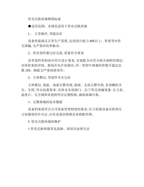
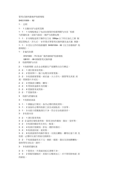
管壳式换热器维护标准
管壳式换热器维修标准
●适用范围:本规范适用于管壳式换热器
1、正常操作,效能良好
设备性能满足正常生产需要,达到设计能力90%以上;管束等内件
无泄漏,无严重结垢和振动。
2、所有部件都完好无损,质量符合要求
各零部件的材质应符合设计要求,安装配合应符合相关规程的规定;壳体管束的冲蚀、腐蚀在允许范围内,同一管程中堵塞的管数不超过总
数10%,隔板无严重扭曲变形。
3、主体整洁,零部件齐全完好
主体整洁,保温、油漆完整美观,基础、支座完整牢固,各部螺栓齐全、牢固,符合抗震要求;壳体及各部阀门、法兰等无渗漏现象;压力表、温度计、安全阀和其他附件应定期校准,确保准确可靠。
4、完整准确的技术数据
设备档案要符合公司设备管理制度的要求;压力容器设备应取得压
力容器使用许可证;应有设备结构图及易损配件图。
3 管壳式换热器的维护
4管壳式换热器常见故障、原因及处理方法。
管壳式换热器的检修与维护
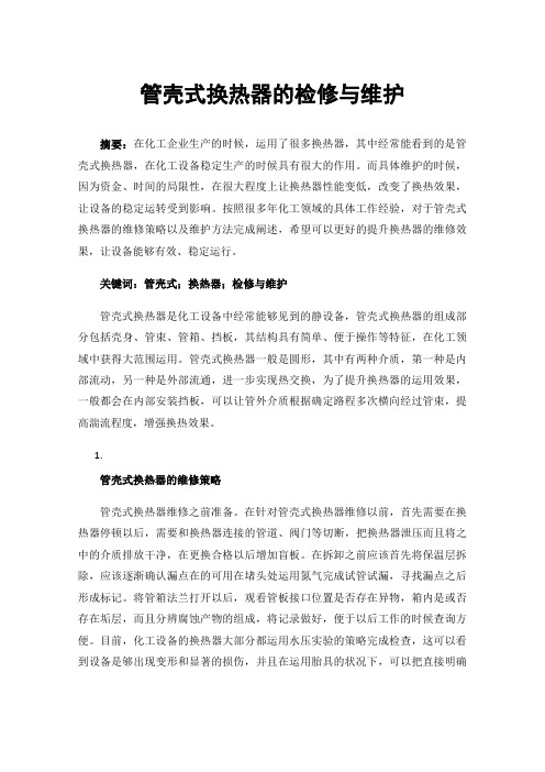
管壳式换热器的检修与维护摘要:在化工企业生产的时候,运用了很多换热器,其中经常能看到的是管壳式换热器,在化工设备稳定生产的时候具有很大的作用。
而具体维护的时候,因为资金、时间的局限性,在很大程度上让换热器性能变低,改变了换热效果,让设备的稳定运转受到影响。
按照很多年化工领域的具体工作经验,对于管壳式换热器的维修策略以及维护方法完成阐述,希望可以更好的提升换热器的维修效果,让设备能够有效、稳定运行。
关键词:管壳式;换热器;检修与维护管壳式换热器是化工设备中经常能够见到的静设备,管壳式换热器的组成部分包括壳身、管束、管箱、挡板,其结构具有简单、便于操作等特征,在化工领域中获得大范围运用。
管壳式换热器一般是圆形,其中有两种介质,第一种是内部流动,另一种是外部流通,进一步实现热交换,为了提升换热器的运用效果,一般都会在内部安装挡板,可以让管外介质根据确定路程多次横向经过管束,提高湍流程度,增强换热效果。
1.管壳式换热器的维修策略管壳式换热器维修之前准备。
在针对管壳式换热器维修以前,首先需要在换热器停顿以后,需要和换热器连接的管道、阀门等切断,把换热器泄压而且将之中的介质排放干净,在更换合格以后增加盲板。
在拆卸之前应该首先将保温层拆除,应该逐渐确认漏点在的可用在堵头处运用氮气完成试管试漏,寻找漏点之后形成标记。
将管箱法兰打开以后,观看管板接口位置是否存在异物,箱内是或否存在垢层,而且分辨腐蚀产物的组成,将记录做好,便于以后工作的时候查询方便。
目前,化工设备的换热器大部分都运用水压实验的策略完成检查,这可以看到设备是够出现变形和显著的损伤,并且在运用胎具的状况下,可以把直接明确单管师傅出现漏点。
将水压实验完以后,就要按照不同的问题运用不同的维修策略,实际如下:1.堵管经过水压实验,就能够知道管道是否泄漏,针对直径相对小的管道,能够运用在其中的一端打盲孔,形成圆柱体的堵管零件。
这可以把管板焊接变形,使压力都集中在堵管中,减轻管板的焊接压力。
管壳式换热器维护检修规程
管壳式换热器维护检修规程SHS 01009—921.总则1. 1 主题内容与适用范围1.1. 1 本规程规定了电动往复泵的检修周期与内容`检修与质量标准、试验与验收、维护与故障处理。
1.1. 2 本规程适用于操作压力在35Mpa 以下的石油化工钢制固定管板式、浮头式、U 形管式等管壳式换热器及釜式重沸器。
1.1. 3 受压元件的检修遵照SHS01004—92《压力容器维护检修规程》。
1. 2 编写依据SY21003 —73 炼油厂换热器维护检修规程GB151 —89 钢制管壳式换热器2 检修周期与内容2. 1 检修周期由各企业根据生产装置特点自行确定。
2.2. 1 清扫管束和壳体。
2.2. 2 管束焊口、胀口处理及单管更换。
2.2. 3 检查修复管箱、前后盖、大小浮头、接管等及其密封面,更换垫片并试压。
2.2. 4 更换部分螺栓、螺母。
2.2. 5 壳体保温修补及防腐。
2.2. 6 更换管束或壳体。
2.2.7 更换壳体。
3 检修与质量标准3. 1 检修前准备3.1. 1 掌握运行情况,备齐必要的图纸资料。
3.1. 2 准备好必要的检修工具及试验胎具、卡具等。
3.1. 3 内部介质置换清扫干净,符合安全检修条件。
3. 2 检查内容3.2. 1 清扫管束壳体3.2.2 温表宏观检查壳体、管束及构件腐蚀、裂纹、变形等。
3.2. 3 检查防腐层有无老化、脱落。
3.2. 4 检查衬里腐蚀、彭包、褶折和裂纹。
3.2. 5 检查密封面、密封垫。
3.2. 6 检查紧固件的操作情况。
对高压螺栓、螺母应逐个清洗检查,必要时应进行表面无损探伤。
3.2.7 检查基础有无下沉、倾斜、破损、裂纹及其地脚螺栓、垫铁等有无松动、损坏。
3. 3 检修质量标准3.3. 1 管束内、外表面结垢应清理干净。
3.3. 2 管箱有隔板时,其垫片应整体加工:并不得有影响密封的缺陷。
3.3. 3 管束堵漏,在同一管程内,堵管数一般不超过其总数的10% 。
换热器检修规范
换热器检修基本规范一、换热器抽芯换热器的抽芯工作是在换热器置换干净以后,工艺确认可以抽芯后进行的。
对于高温处的螺栓应该提前涂抹松动剂,防止在松卸困难甚至卡死,管箱卸下以后,便可以进行抽芯工作。
拆管箱和抽芯过程中,对于可能有危险介质存在的部位,要高度小心,避免发生事故。
换热器的抽芯过程中,首先使用管板上定位吊耳将管束抽出一部分,待拉出的距离可以使用辅助机械后便可将管束抽出。
在抽芯的过程中需要注意几个方面:(1)定位吊耳应位于水平位置拉出,这样可以保证换热器的滑道位于受力位置(及垂直方向),承受换热器的重力,避免管束直接受力,同时避免折流板把壳体划伤。
(2)在吊装的过程中,也要保证定位吊耳的水平度,保证管束不垂直受压;吊装用钢绳要用专业的保护套保护,不至使管束受伤(特别是有涂层,可以防止涂层剥落),钢丝与管束接触部位一定要加以保护。
抽芯完成后,要放置在专用的垫具上,一般为具有与换热器吻合面的枕木,不得直接将换热器管束直接放置在平地上。
放置时,管板与管束的连接处不得受力,及管板应悬空,枕木放在管束下,最好滑道与枕木接触,直接受力。
二、换热器的清洗换热器清洗一般在专门的清洗场地进行,如时间紧迫需在装置内进行,应注意安全和场地卫生。
换热器的清洗分内壁清洗和外壁清洗两部分:(1)内壁清洗使用细管长枪,首先确保管束畅通,其次清除管内污垢、结焦等。
在清洗时,应正反两个方向冲洗同一根管,以保证清洗效果。
对结焦比较严重的管子,应使用较长的水枪冲洗。
冲洗的后管束应畅通,且水柱喷射均匀(内径未因结焦、污垢无而变小)。
(2)外壁清洗使用旋转多头水枪和长管水枪相结合。
无论管束按照哪种形式排列,总有一个平面可以贯通两侧的所有管束,清洗时应使用长管水枪清洗这个空间,并做正反两方面冲洗。
对于防冲板下管束的清洗比较困难,是一个死区,应多次清洗以保证效果。
在清洗过程中,应有吊机配合,使管束可以翻身清理,以便达到理想的效果。
(3)清洗效果的检查也主要分以上两个方面,外壁目测,特别是可以贯通的平面空间;管内则需要抽查,可选择“十字交叉”法选择抽查样本,这样可以比较全面的了解清洗的情况。
管壳式换热器维护检修规程

管壳式换热器维护检修规程(ISO9001-2015)1.0目的及范围本规程规定了管壳式换热器的完好标准,安装与试车、维护及故障处理。
本规程适用于我企业中设计压力不大于 6.4MPa、设计温度大于-20℃、小于520℃的管壳式换热器的维护和检修。
管壳式换热器(包括因定管板式、浮头式、U形管式和填料函式)主要由外壳、管板、管束、顶盖(封头)等部件构成。
固定管板式换热器的两端管板,与壳体焊接相连,为减小温差引起的热应力,有时在壳体上设有膨胀节。
浮头式换热器的一端管板固定在壳体与管箱之间,另一端管板可以在壳体内自由移动。
U 形管式换热器的换热管弯成U形,两端固定在同一管板上,管束可以自由伸缩。
填函式换热器的一端管板固定,另一端填函密封可以自由伸缩。
2.0完好标准2.1零、部件2.1.1换热器的零、部件及附件完整齐全,壳体、管程、板片、封头的冲蚀、腐蚀在允许范围内,管束的堵管数不超过管束总数的10%,隔板、板片、折流扳、防冲板等无严重的扭曲变形。
2.1.2仪表、计器和各种安全装置齐全,完整,灵敏,准确。
2.1.3基础、机座完好,无倾斜、下沉、裂纹等现象。
2.1.4各部连接螺栓、地脚螺栓紧固整齐、无锈蚀,符合技术要求。
2.1.5管道、管件、阀门、管架等安装合理、牢固完整、标志分明、符合要求。
2.1.6换热器壳程、管程及外管焊接质量均符合技术要求。
2.1.7防腐、保温设施完整有效,符合技术要求。
2.2远行性能2.2.1换热器各部温度、压力、流量等参数符合技术要求.2.2.2设备各部阀门开关正常。
2.2.3换热效率达到铭牌出力成查定能力。
2.3技术资料2.3.1设备档案、出厂质量证明书、检修及验收记录齐全.2.3.2压力容器的技术资料齐全、准确。
2.3.3运行时间和累计运行时间有统计记录。
2.3.4设备图纸齐全。
2.3.5操作规程、维护检修规程齐全。
2.4设备及环境2.4.1设备及环境整齐清洁、无污垢、垃圾。
2.4.2设备的胀口、焊口、管口、法兰、阀门、填料函及换热板间等密封面完好,泄漏率在允许范围内。
- 1、下载文档前请自行甄别文档内容的完整性,平台不提供额外的编辑、内容补充、找答案等附加服务。
- 2、"仅部分预览"的文档,不可在线预览部分如存在完整性等问题,可反馈申请退款(可完整预览的文档不适用该条件!)。
- 3、如文档侵犯您的权益,请联系客服反馈,我们会尽快为您处理(人工客服工作时间:9:00-18:30)。
Maintenance and Service Procedure for Petrochemical Equipment--General EquipmentMaintenance and Service Procedure for Shell and Tube Heat Exchang er(管壳式换热器爱护检修规程)SHS 01009-92(For Trial Implementation)Promulgated by SINOPECSINOPEC Publishing HouseContents1 General 22. Period and Content of Maintenance 23. Maintenance and Quality Standard 34. Testing and acceptance 95. Service and Troubleshooting 121 General1.1 Subject and scope1.1.1 This procedure specifies the period and content of maintenance, maintenance and quality standard, testing and acceptance, and service and troubleshooting of heat exchanging equipment.1.1.2 This procedure is applicable to the petrochemical steel shell-and -tube heat exchangers like fixed tubesheet exchanger, floating-head exchan ger, U-tube exchanger etc., and kettle-type reboilers, with operating pressu re below 35Mpa.1.1.3 The service of pressure elements shall comply with SHS01004-92 “Maintenance and Service Procedure for Pressure Vessels”1.1.4 ReferencesSY21003-73 Maintenance and Service Procedure for Heat Exchang er in Oil RefineryGB151-89 Steel Tubular Exchanger2. Period and Content of Maintenance2.1 Maintenance periodThe maintenance interval can be determined by individual enterprise according to the features of its production equipment.2.2 Maintenance content2.2.1 Cleaning tube bundle and shell.2.2.2 Welding joint and expanded joint treatment of tube bundle and the replacement individual tube.2.2.3 Check and repair the tube box, front and back cover, small and big floating heads, and fittings etc., as well as their seal faces, replace g askets and test with pressure.2.2.4 Replace some of the bolts and nuts.2.2.5 Repair the thermal insulation of the shell and make anticorrosio n treatment2.2.6 Replace the tube bundle or the shell.2.2.7 Replace the shell.3. Maintenance and Quality Standard3.1 Preparations prior to Service3.1.1 Have full knowledge of the operation conditions, and make all the necessary drawings and documents at hand.3.1.2 Prepare all the necessary service tools, test stand, clamping app aratus etc.3.1.3 Displace and clean out the internal fluid, to meet the requireme nts of safety service.3.2 Content of the inspection3.2.1 Clean the tube bundle and shell.3.2.2 Inspect visually the shell, tube bundle, and components for any corrosion, crack, deformation, etc. Have a spot check with surface flaw detection, if necessary.3.2.3 Inspect the anticorrosive coating for any sign of aging and peel ing off.3.2.4 Inspect the lining for any corrosion, swell, fold, and crack.3.2.5 Check the seal faces and the gaskets.3.2.6 Check the wear condition of the fasteners. Clean and examine t he high-pressure bolts and nuts one by one, and carry out surface nondest ructive inspection if necessary.3.2.7 Inspect the foundation for any settlement, inclining, damage and crack. Check its anchor bolts and pats to see if they are loosened and d amaged.3.3 Maintenance quality standard3.3.1 The scaling on the inner and outer surface of the tube bundle shall be cleaned out.3.3.2 In case there is a partition plate in the tube box, its gaskets sh all be machined monolithically, and shall be free of any defects that may affect the sealing.3.3.3 When blocking leaking tubes of tube bundles, on the same tube side, the number of tubes being blocked to stop leaking shall not exceed 10% of the total number of the tubes. Within the allowed range of proc ess index, the number of blocked tubes may be increase by an appropriate amount.3.3.4 All the parts and components used shall conform to the relevan t technical specifications, and shall be provided with certificate of complia nce for materials.3.3.5 Replacing tube bundles3.3.5.1 The tube surface shall be free of such defections as cracks, f olds, double-skin, etc.3.3.5.2 When it is necessary to splice the tubes, only one welding jo int as maximum is allowed on the same heat exchanging tube (U-tube ma y have two welding joints). The minimum tube length shall be no less th an 300mm and no welding joints for splicing shall not be allowed within the elbow section of U-tube, while the length of straight tube section sh all be no less than 50mm, and the unfitness of butt joint shall not exceed 15% of the tube wall thickness and not be greater than 0.5mm.3.3.5.3 Test the hardness of the tubes. Normally it is required that the hardness of the tube shall be 30HB lower than that of the tube sheet. I n case the tube hardness is higher than or closer to the tubesheet hardnes s, the annealing treatment shall be made to the two ends of the tubes. Th e tube length subjected to the annealing treatment shall be 80mm~100mm longer than the thickness of the tube sheet.3.3.5.4 The ends of the tube shall be clean and free of grease and d irt, and shall not have any defects that may affect the tightness of the ex panded joints, such as penetrated, longitudinal or spiral scores.3.3.5.5 The both ends of tubes shall project beyond the tube sheets, and the length of the tube ends projected from the tube sheets shall be 4 1mm.3.3.5.6 The degree of expanded tube joint shall be within the range of 0.7~1.6%.(d’ID –dID) –(d0 –d)Degree of expanded tube joint = 10 0%d0where: d’ID the inside diameter of the tube after expanded for joint;dID the inside diameter of the tube before expand ed for joint ;d the outside diameter of the tube before expanded for joint ;d0 t he aperture of the tubesheet before expanded for joint.3.3.5.7 The expanding operation should not be carried out at a tempe rature below 0oC. After expansion, the expanded section and the transitio n section of the tube shall be smooth, without any crack and groove. The re-expansion of each expand shall not exceed twice.3.3.5.8 When welding the tube and tubesheet together, the surface of the cut on the tube shall be smooth, and free of burrs, convex and conc ave, crack and lamination, and the position for welding shall be free of such foreign matters as slag, iron oxide and greasy dirt, which may affect the welding quality.3.3.6 The integral replacement of the tube bundle shall be carried out according to GB151-89 “Steel Tubular Exchanger”or the requirements of design drawing.3.3.7 The repair of the shell shall be made according to SHS01004-92 “Maintenance and Service Procedure for Pressure Vessels”3.3.7.1 After repair welding, the steel plate, which has been heat-treat ed before, shall be retreated.3.3.7.2 Pass the pressure-tight test or air-tightness test.3.3.7.3 Data and records are complete.3.3.8 The replacement of gaskets shall comply with the design requir ements, or refer to Table 1.Note: ①Benzene can dissolve the acrylonitrile rubber in the oil-resis tant rubber asbestos gasket, therefore PN≤2.5MPa.②For benzene medium with temperature lower than or equal t o 200oC, the wound type gasket shall also be used.③It is not suggested to select the non-metal soft gaskets for the internal connection of floats, etc.④Wound type gasket or clad rubber asbestos plate should be selected for the inflammable, explosive, poisonous, and easy permeable m edia.⑤The wound type gasket normally is not applicable to the fla nge with flat facing.3.3.9 When it is necessary to replace the bolts and nuts on the exch anger, they shall be selected and used according to the design requirement s or with reference to Table 2.3.3.9.1 The threads shall be free of burrs and flaws. Thread with slig ht local fracture shall not exceed 1/4 of one turn, and the total length of such thread shall not exceed one turn.3.3.9.2 For bolts with operation temperature over 250oC, the anti-occl usion agent shall be applied during the assembling.3.3.10 Cold exchanging equipment with anticorrosive coating3.3.10.1 Check the coating of water coolers visually, and make sure t he surface is smooth, without any phenomenon of dripping, flow, missing coating, etc.25Cr2MoV A 30Cr2MoA - 20 ~ +500 25Cr2MoV A - 20 ~ +550 1Cr5Mo 1Cr5Mo - 20 ~ +600 2Cr13 1Cr13, 2Cr13 - 20 ~ +450 0Cr19Ni9 25Cr2MoV A - 20 ~ +550 0Cr19Ni9 - 196 ~ +700 0Cr17Ni12Mo20Cr17Ni12Mo2- 196 ~ +7003.3.10.3 When handling, installing, servicing and cleaning the equipm ent, care shall be taken not to damage the anticorrosive coating.4. Testing and acceptance 4.1 Testing4.4.1 The service records shall be complete and correct.4.1.2 The construction unit shall confirm that the quality is acceptabl e, and conditions for test are fulfilled.4.1.3 Pressure test4.1.3.1 The test value shall adopt the larger one obtained from the f ollowing formulas:a. Hydraulic pressure test valuePT = ⎪⎩⎪⎨⎧+1.0][][25.1P Pt σσb. Air pressure test valuePT = ⎪⎩⎪⎨⎧+1.0][][15.1P Pt σσWhere: PT the test value of pressure-tight test, MPa;P the maximum operating pressure of the tube sideor shell side, MPa;[] the allowable stress of the material under test temperature, MPa;[ ]t the allowable stress of the material under the ope rating temperature,Mpa;[][ ]t4.1.3.2 When making the pressure test, the pressure shall be increase d gradually to the specified value. Holding time of constant pressure for l ow-pressure heat exchanger shall not be less than 5min, for medium and high pressure heat exchanger shall not be less than 20min. Then, reduce to the operating pressure and make careful inspection. Exchangers withou t fracture, leakage and residual deformation will be taken as qualified. If there are problems as leakage etc., the exchanger shall be re-tested after t he remedy is made.4.1.3.3 Sequence and requirements of pressure test 4.1.3.3.1 Fixed tubesheet exchangera. Pressure test of shell side: check the shell body, the joints to conn ect heat exchanging tubes with the tube sheet, and other related positions.b. Pressure test of tube side: check the tube box and other related p ositions.4.1.3.3.2 U-tube exchanger, kettle-type reboiler (with U-type tube bun dle) and stuffing box exchangera. Pressure test of shell side (use the proving ring): check the shell body, tube sheet, the connections between heat exchanging tubes and tube plate, and other related positions.b. Pressure test of tube side: check the related positions of the tube box.4.1.3.3.3. Floating heat exchanger, kettle-type reboiler (with floating-h ead tube bundle)≥ 1.8, the value 1.8 will be taken for the calculation.Whena. Make pressure test to the connections between the tubes and tubes heet with proving ring and special pressure test tools for floating head. F or kettle-type reboiler, a special shell for pressure test on the connections between the tubes and tubesheet shall also be used, in order to check th e connections between heat exchanging tubes and the tube sheet, and the related position.b. Pressure test of tube side: check tube box, floating head and the r elated positions.c. Pressure test of shell side: check the shell body, connections betwe en heat exchanging tubes and tube plate, and the related positions.4.1.3.3.4 When test pressure of the tube side is higher than that of t he shell side, the pressure test of connections shall follow the specificatio n on the drawing, or the method agreed by both the production unit and the construction unit.4.1.3.3.5 Overlapping heat exchangerThe pressure test for joints shall be carried out on the unit-by-unit b asis. When the ranges of sides for each heat exchanger are jointed togeth er, the pressure test of tube side and shell side shall be carried out after the overlapping assembling. Check the seal on the connecting flange.4.2 Acceptance4.2.1 After the equipment has been put into operation for one week, all the indexes shall reach the technical requirements or meet the producti on needs,4.2.2 The anticorrosion of the equipment is well preserved without an y damage, and meets the standard of intact.4.2.3 Submit the following technical documents4.2.3.1 Notices for design change and material substitution, and the c ertificates of compliance for materials and parts.4.2.3.2 Service records.4.2.3.3 Inspection report on the quality of welding joints (including v isual inspection and nondestructive test).4.2.3.4 Test records.5. Service and Troubleshooting5.1 Routine maintenance5.1.1 Carefully check the operation parameters of the equipment. Ove r-temperature and over-pressure are strictly prohibited.5.1.2 The operator shall strictly observe the safety operation proceudr es, conduct regular tour inspection to the heat exchanging equipment, to c heck for the stability of its foundation and supports, and the leaking of t he equipment.5.1.3 When the cold exchanging equipment with anticorrosive coating is under operation, the temperature shall be strictly controlled in order to avoid the damage to the coating.5.1.4 Maintain the completeness of the insulation.5.1.5 Painting the equipment periodically to prevent corrosion.5.2 Common troubles and troubleshooting (see Table 3)Additional Note:Jinxi Refinery and Petrochemical Plant is responsible for the draft of this procedure.The draftsman of this procedure is Mr. Xu Zhongliang.。