ENTECH3100A中文操作手册
3100溶氧仪中文操作手册

3.1 概述............................................................................................................................................ 15 3.2 拆箱............................................................................................................................................ 15 3.3 您接收到的物品.......................................................................................................................... 15 3.4 安装开始检查单.......................................................................................................................... 16 3.5 重新连接电池 ............................................................................................................................. 17 3.6 仪器开关和连接器 ...................................................................................................................... 18 3.7 仪器接口..................................................................................................................................... 20
德国耶拿toc3100说明书
德国耶拿toc3100说明书一、开关机1、打开氧气瓶总阀,调整氧气减压阀的分压阀至兆帕(MPa)。
2、打开主机电源。
3、打开计算机电源。
4、待主机指示灯变绿后,双击multiWin图标,打开软件。
5、输入软件口令(Admin),然后点击OK。
6.关机。
选择退出(EXIT)按扭,退出软件,关闭主机电源,关闭自动进样器电源,关闭计算机电源,将氧气瓶总阀关闭,松开氧气瓶分压阀。
二、新建方法选择方法,选择新建F6,在名称中键入新文件名后,选择测量参数(如NPOC、TOC),选择测量次数重复(如2-3),选择测试精度要求变异系数(如2%),点击处理参数选项卡,选择样品体积(如200ul),设置NPOC吹扫时间,最大积分时间(如:180s,180S)。
点击保存,点击确定此方法,再次点击确定此方法作为当前的测量方法。
载入已存方法:选择方法—载入F7载入已存方法,点击确认。
已存方法中已包含校准曲线,可用一点标准样品来检验校准曲线是否满足测试要求(校准曲线是否漂移),如果校准曲线满足测试要求,可直接测试样品,否则需重新制作校准曲线。
三、标准曲线的制作点击开始校正,点击yes确定,再次点击yes确定采用当前方法,选择校正类型(例如用固定浓度校正),编辑校准曲线的标准样品份数(4个以上),输入标准液浓度(mg/L)以及进样体积,点击测量(Measurement),然后再点击“启动F2”,仪器将自动测试样品。
校准曲线做好后,仪器将自动弹出校准曲线表,你可通过选择标准样品点数来修改校准曲线。
校准曲线修改后,点击方法连接,点击yes确定此方法,点击接收值,校准曲线的K1、K0将变为新值。
点击关闭当前对话框,再关闭校准曲线对话框。
四、样品测量点击开始测量,输入样品名称及样品表名称,点开始,自动进样器对话框将弹出,在样品ID栏中输入相应名称后,点击开始键,在弹出对话框中选择是否保存样品表,然后再点击“启动F2”,仪器将自动测试样品。
sitemaster S331天馈线测试仪使用指南
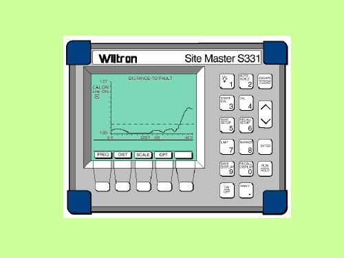
WILTRON SITE MASTE S331测试仪使用指南一、Site Master 331测试仪操作键示图二、测试仪表预调1. 选择频率范围-按ON按钮打开SiteMaster。
-按FREQ 软键。
-然后按F1 软键。
-输入天线系统的下限(“Lower”)频率MHz值,按ENTER键。
-再按F2 软键。
-输入天线系统的上限(“Higher”)频率MHz值,按ENTER键。
-在显示区域显示新的开始与结束值的地方检查频率数值范围FREQ scale。
-按MAIN 软键进入主菜单。
2. 测试仪表较准Open---开路器Short---短路器Load---负载器-将测试口扩充电缆(the test port extension cable)连到测试端口。
-按START CAL 键。
-连接标记为“OPEN”端的Open/Short器到测试扩充电缆的末端,然后按ENTER。
Result: 在测试处理过程中“Measuring OPEN”(测试开路)的信息将显示在屏幕上。
-连接标记为“SHORT”端的Open/Short器到测试扩充电缆的末端,然后按ENTER。
Result: 在测试处理过程中“Measuring OPEN”(测试开路)的信息将显示在屏幕上。
-连接“PRECISION LOAD ”(负载器)到测试扩充电缆的末端,然后按ENTER。
Result: 测量后,“Measuring LOAD”的信息显示在屏幕上,“Calculating”显示约8秒-校准完毕后, 从测试扩充电缆取下“PRECISION LOAD”器。
3. 输入天馈线的参数-按DIST 软键。
-按MORE 软键。
-按LOSS 键。
-输入要测试的天馈线类型的每米的损耗dB值(see Table 23) ,然后按ENTER.注意: 只有采用供货商提供的正确值,才能保证测试结果的可靠性。
-再按PROP V 软键。
-输入relative velocity (see Table 23) 测试天馈线的类型,然后按ENTER键。
Y331A使用说明书
一、产品用途本仪器用于测定各种纱线的捻度。
采用中文界面,使用简单方便。
仪器性能符合:国家标准GB2543.1- GB2543.2《纺织品纱线捻度的测定》国际标准IS02061《纺织品纱线捻度的测定直接计数法》纺工部标准FJ547《本色气流纺棉纱试验方法》国家行业标准FZ/T10001《气流纱捻度的测定——退捻加捻法》二、主要技术指标2.1 测试范围:各种纱线。
2.2 纱线张力:有一组砝码可根据纱线的类别进行调整。
2.3 夹头转速:1000r/min 、1500r/min点动慢速。
2.4 测试长度:25、50、100、200、250、500mm。
2.5 测试数量:小于99次。
2.6 测试方式:a、直接计数法;b、退捻加捻法(一次法);c、退捻加捻法(二次法);d、三次退捻加捻法;2.7 测试数据输出方式:2.7.1 显示输出:每次捻度值Xi;每批平均捻度值eX;不匀率H;变异系数CV,捻系数α。
2.8 电源:220V±10% ,50Hz。
2.9 功率:小于25W(主机)2.10使用环境要求:温度20±10℃三、外形图(见图一)四、主要结构本纱线捻度仪主要由控制箱、张力机构、插纱架及数据处理系统等部件组成。
4.1 制箱装有右夹头,各个功能开关,右夹头由微电机直接带动。
4.2 张力机构是采用水平机械式加载张力方法,其张力用砝码按试验方法的要求进行任意调节。
4.3 插纱架可由用户自由地安装和调节来满足试验的要求。
4.4 数据处理系统主要有机内计算机,显示器等组成。
五、仪器的安装与调整5.1 拆开包装时,必须先打开木箱顶盖,再拆除四侧箱板,然后小心取出仪器,插纱架及打印机。
5.2 搬运仪器时,只允许仪器底座受力,不允许其它部分受力。
5.3 仪器必须安放在水平坚固的工作台上,用软布擦干净仪器的外表面,然后在仪器左边放置好插纱架,并将砝码安置在砝码轴上。
5.4 仔细检查一下仪器各零部件是否有因运输过程中或拆箱过程中产生的损坏、变形、松动等情况。
Netgear_CG3100使用说明书

Prohibition of Collocation
This device and its antenna(s) must not be collocated or operating in conjunction with any other antenna or transmitter.
Safety Information
Declaration of Conformity for R&TTE directive 1999/5/EC
Essential requirements – Article 3. Protection requirements for health and safety – Article 3.1a. Testing for electric safety according to EN 60950-1 has been condБайду номын сангаасcted. These are considered relevant and sufficient. Protection requirements for electromagnetic compatibility – Article 3.1b. Testing for electromagnetic compatibility according to EN 301 489-1 and EN 301 489-17 has been conducted. These are considered relevant and sufficient. Effective use of the
ENTECH3100A中文操作手册
3100A自动清罐仪简介3100A自动清罐仪利用干净的空气或者氮气通过循环抽气和充气来同时清洗一个或者多个不锈钢采样罐.抽气时,粗真空将用一级隔膜泵获得,高真空将用分子涡轮泵获得.加湿管用来加湿清洗气来帮助除去管路和采样罐内壁的挥发性有机物.利用加热带或加热箱对采样罐加热也可以帮助清除污染物.这一点很重要,因为在大于常压取样的时候,它经常导致在采样罐内形成冷凝物.3100A可以多次循环清洗管路和采样罐,可以因不同批次的采样罐设置不同充气压力和循环清洗次数.当样品气达到PPM级清洗要达到10到20次左右,如果是高PPM级的样品使用后,第一次清洗过后要在真空条件下保存一周左右,然后再一次清洗.3100A也可以单独使用某一个泵来工作,而且通过软件还可以检查系统是否漏气以及给清洗后的采样罐保持高真空状态.3100A可以自动进行清洗,也可以手动进行清洗.自动清洗利用软件设置清洗参数,手动清洗可以单独设置使用一级隔膜泵或者二级分子涡轮泵以及填充氮气.利用3100A的真空状态也可以对管路进行检漏和检验泵的最终的抽气能力.SmartLab控制软件介绍SmartLab仪器控制网络集中控制空气实验室仪器在一个通用的PC控制的Microsoft Windows 2000或者XP操作系统。
一个单独的计算机(奔腾Ⅱ400或者更好)控制GC/MS,7100预浓缩仪,7106CA罐自动进样器,7032迷你罐自动进样器,31位罐清洗,3100A自动清罐仪和4600动态稀释仪的操作。
所有Entech 总线上的外设都使用同样的控制电路。
模块化有许多好处,包括易于维修,减少配件数量,有利于使用者自己更好的了解产品。
熟悉了一个SmartLab产品后,其他的产品就变得更容易理解和操作。
软件使用USB HUB(可选件)可以将多个ENTECH产品连接到一台电脑上,当使用Microsoft Windows 2000或者XP操作系统时,软件检测到USB端口,然后安装USB驱动程序,即可控制ENTECH的产品.安装拆包把3100A从包装箱中取出,平稳的放在工作台上,地面上有合理位置摆放一级隔膜泵,同时还需要考虑如何来摆放采样罐以及如何设置零空气或者高纯氮气连接口.气路连接3100A需要使用高纯氮气或者零空气首先加水,通过3100A后的液位计观察水位液面,不能超过液位的一半,否则水就会进入气路,不能够获得足够高的真空状态.用1/4的铜管线从氮气出口到加湿器入口用1/8的铜管线从加湿器出口到3100A后的“FILL GAS IN”接口处.将采样罐用3/8螺母或者快速连接头连接在3100A支架上.将1/4软管安装在一级隔膜泵和3100A后的ROUGH PUMP接口处.检漏3100A在安装好后要检漏以保证系统在密闭条件下工作.检漏可以通过观察抽气后系统的真空度增加来确定系统密闭程度.用1/4接头将系统密闭.打开工作站,点泵1,当压力达到3个PSI以下后,点泵2,系统会很快达到2000毫脱以下.如果真空度不能在5分钟内达到50毫脱以下,则说明系统漏气或者管路中有积水.如果有水存在的话,管壁会很凉,可能因为那里的水来自汽化池被加热后产生的蒸气或者因为系统在35-40PSI压力下10分钟以上没有气体流动.如果管路里有水,请先确认水线在水位满刻度一半以下,然后做至少50次的清洗,而且在每次清洗时,要使分子涡轮泵至少运行1分钟.如果不能达到高真空或者不能保持压力,那么系统漏气就是存在的.漏气的地方可以用给系统加大气压然后使用电子检漏装置检查.如果在采样罐被连接到3100A支架上做真空检漏的时候漏气,要意识到漏气可能由于采样罐的阀漏气引起的.当系统使用泵2工作的时候,轻轻关闭采样罐的阀,观察高真空读度是否发生变化.发现漏气原因和找到解决漏气方法后,重新启动系统检漏测试.操作概要采样罐成功清洗包括很多因素,包括污染物的等级、最后样品的压力和湿度、存储的时间、采样罐内表面当前条件.最小温度和需要循环的次数是根据这些因素而变化的.两个泵都要使用是因为没有任何一个泵可以完全达到设计的要求.无油隔膜泵不能达到真空度很高的要求,最好的无油隔膜泵也不能把真空达到5-10毫脱以下.同样的,涡轮分子泵在高压力下保持10-20秒大体积气体抽取就会损坏.首先打开采样罐的阀,然后泵1抽粗真空,然后泵2再进一步抽真空.自动充气程序通过已经设置的泵1泵2和充气时间或者通过设置给定压力和真空度来达到.最典型的设置就是3次清洗采样罐,对于大多数采样罐来说,3次清洗足够了.在经过自动循环设定的次数后,系统将进入最后一次抽气过程,使用者通过一级泵和二级泵的工作将达到设定的真空度或时间,最后的真空度将保持在50-100毫脱之间.对环境样品的处理如果采样罐用来采集环境中的VOCS成分,每种成分物质的量仅在检测限的1-100倍左右,所以只需要很少的清洗次数就足够了.然而,在加压处理高湿度样品时,冷凝物会在罐内形成.聚合反应会发生在冷凝物离开污染物表面的时候.这些污染物会影响今后VOCS的取样和分析.通过提高温度增加清洗次数可以消除这些影响.通常情况下,温度从50度到100度的3或4次清洗就可以了.在进行这个操作的时候,设置填充压力大约25个PSI,确定加湿器水位保持在20%-50%之间.在缺省设置方法里,泵1、泵2和充气压力分别设置为2PSI、2000毫托和25PSI,清洗次数要看每批采样罐的数量和体积.在抽气压力达到后,会听到罐有气体流动声音,那表明抽气结束开始充气了.当使用支架时,要把采样罐吊在支架上.把加热带绑在能够最大限度的加热采样罐的地方.在打开采样罐的阀准备清洗前,要检漏.手动启动泵1到2PSI以下,然后启动高分子泵,如果压力在这样的条件下不能达到50-100毫托,那清洗就不能完成.允许系统在5分钟内达到最佳真空度,然后给采样罐加热,看真空度是否有改善.在检查了所有接头后,试着给采样罐的阀加热,然后观察真空度.一个坏的阀也会引起少量漏气.在关闭采样罐的阀的时候要轻用力,以免损坏阀.用大拇指和食指抠住阀就可以将阀很容易的打开和关闭.在达到合适的真空后,选择或者创建一个方法然后选择“GO”在“RUN”的显示窗口中.打开加热带或烘箱电源,对采样罐加热,采样罐在第二次循环的时候就可以达到合适的温度.在采样罐达到最后真空后,关闭采样罐的阀并关闭加热带或烘箱的电源.对污染样品的处理用来处理污染样品的采样罐不能在没有认真清洗或证明了没有清洗的情况下给环境样品进行使用.如果想重新做环境样品,一定要认真清洗。
STARTER 3100C 实验室 电导率仪 使用说明
STARTER 3100C 实验室电导率仪使用说明书奥豪斯仪器(上海)有限公司沪制01040072号目录1简介 (2)1.1安全与防护措施 (2)1.2显示与按键 (3)2安装 (5)2.1配置与选配件 (5)2.2安装支架 (5)2.3连接电源 (6)2.4安装电极 (6)2.5仪表支脚与视角调整 (6)3STARTER 3100C 电导率仪操作 (7)3.1校准 (7)3.1.1选择校准溶液 (7)3.1.2电极校准 (7)3.2样品测量 (8)3.3TDS与盐度测量 (8)3.4使用存储器 (9)3.4.1存储读数 (9)3.4.2调取存储数据 (9)3.4.3清除存储数据 (9)3.5打印 (9)4参数设置 (11)4.1设置温度单位 (11)4.2手动设置温度值 (11)4.3设置校准的标准溶液值 (11)4.4设置温度补偿系数 (11)4.5设置参比温度 (11)4.6设置 TDS 因子 (12)5维修保养 (13)5.1出错信息 (13)5.2仪表维护 (13)5.3仪表自检 (14)5.4恢复出厂设定 (14)6技术参数 (15)7附录 (16)表 1 电导标准溶液 (16)表 2 温度补偿系数实例 (α值) (16)1简介感谢您选择了奥豪斯公司的高品质产品。
在您使用前,请仔细阅读本说明书,将对使用及维护本仪器有很大的帮助。
STARTER 3100C是一款0.5级(参考JJG376-2007)的实验室台式电导率仪。
可广泛应用于大专院校、研究所、工业企业、环保检测等实验室。
奥豪斯产品具有具有简洁的用户界面,易于操作,仪表质量可靠稳定;为您提供更具性价比的产品是奥豪斯公司的一贯追求。
STARTER 3100C具有很多独特的设计:包括了创新易用的独立电极支架,报错蜂鸣器;配合四环电导电极让您的测量范围更广,结果更准确。
另外99组存储数据,RS232可连接打印机打印,仪表自带快速操作指南等给您带来更多便利。
NETGEAR ReadyNAS 3100 安装指南说明书
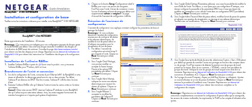
Guide d'installationReadyNAS™ 3100 NETGEAR®Installation et configuration de baseVeuillez suivre les instructions ci-dessous pour installer votre ReadyNAS™ 3100 NETGEAR®.Durée approximative de l'installation : 20 minutes.Remarque : Ces instructions sont rédigées pour une configuration équipée de disques gérée en mode X-RAID2 par défaut. Une unité sans disque nécessite l'installation des disques et l'initialisation du RAID avant de continuer. Consultez la page /hcl pour obtenir une liste des disques pris en charge. Reportez-vous au Manuel de l'utilisateur du ReadyNAS 3100 pour obtenir des instructions sur l'installation des disques et la configuration RAID.Installation de l'utilitaire RAIDar1. Installez l'utilitaire RAIDar à partir du CD fourni avec le produit ; vous y trouverezl'utilitaire RAIDar pour Windows, MAC et Linux.Branchement de l'unité et connexion1. Lors de la configuration de l'unité, connectez le port Ethernet LAN1 du ReadyNAS à votreréseau et allumez-le. Le démarrage prend environ une ou deux minutes. Par défaut, l'adresse IP est obtenue via DHCP . Une fois trouvée, l'adresse IP s'affiche dans la zone d'état.2. Exécutez l'utilitaire RAIDar afin qu'il détecte l'unité et toutes les autres unités sur le mêmesous-réseau.Conseil : Dans votre serveur DHCP , réservez l'adresse IP attribuée à votre ReadyNAS afin qu'il utilise toujours cette même adresse. Ainsi, les unités mappées fonctionnent de manière homogène sur n'importe quel système d'exploitation.ReadyNAS™ 3100 NETGEAR®3. Cliquez sur le bouton Setup (Configuration) relatif à RAIDar pour ouvrir une session de navigationFrontView avec l'unité. L'écran de connexion s'ouvre. Le nom d'utilisateur et le mot de passe par défaut sont respectivement admin et netgear1. La page d'accueil de l'assistant de configuration s'affiche.Exécution de l'assistant de configurationL'assistant de configuration vous explique comment configurer les paramètres de base et partager les fichiers.Remarque : Si vous souhaitezdésactiver l'assistant de configuration, assurez-vous de configurer les alertes et les adresses électroniques, de modifier le mot de passe admin et d'indiquer une question pour la récupération du mot de passe.1. Par défaut, l'assistant deconfiguration est activé lorsqu'il est connecté à l'unité. Cliquez sur Next (Suivant) pour utiliser l'assistant.2. Sous l'onglet Clock (Horloge),vous pouvez modifier ou accepter le fuseau horaire, l'heure et les options NTPparamétrées par défaut. Cliquez sur Next (Suivant) pour continuer.3. Sous l'onglet Alerts (Alertes),indiquez au moins une adresse électronique pour recevoir les alertes du système. Cliquez sur Next (Suivant) pour continuer.4. Sous l'onglet Ethernet 1,acceptez ou modifiez les paramètres de l'adresse IP .Cliquez sur Next (Suivant) pour continuer.5. Sous l'onglet Global Settings (Paramètres globaux), vous avez la possibilité de modifier lenom d'hôte de l'unité. Par ailleurs, si vous optez pour une configuration IP statique, vous devrez configurer la passerelle et les paramètres DNS (vous n'avez pas besoin demodifier ces paramètres si vous utilisez l'unité dans sa configuration DHCP par défaut). Cliquez sur Next (Suivant) pour continuer.6. Sous l'onglet Admin Password (Mot de passe admin), modifiez le mot de passe du systèmeet indiquez une question de récupération, sa réponse et une adresse électronique.Veuillez noter ces modifications. Cliquez sur Next (Suivant) pour continuer.7. Sous l'onglet Security Mode (Mode de sécurité), sélectionnez l'option « User » (Utilisateur)par défaut qui permet de contrôler l'accès aux partages en fonction des comptes clients ou de groupe. FrontView essaiera de détecter le premier nom de groupe de travail présent sur le réseau. Dans le cas contraire, « VOLUME » sera le nom par défaut du groupe de travail. Indiquez le nom du groupe de travail auquel votre unité doit seconnecter. Reportez-vous au Manuel de l'utilisateur du ReadyNAS 3100 pour obtenir des instructions d'installation ACS. Cliquez sur Next (Suivant) pour continuer.8. Sur la page Accounts (Comptes), cliquez sur Add User (Ajouter un utilisateur). Ajoutezun nouvel utilisateur et un mot de passe d'utilisateur. Cliquez sur Next (Suivant) pour terminer la procédure d'installation avec l'assistant. Reportez-vous au Manuel de l'utilisateur du ReadyNAS 3100 pour obtenir des instructions complètes sur la configuration de comptes. Remarque : Reportez-vous au Manuel de l'utilisateur du ReadyNAS 3100 pour obtenir des instructions complémentaires concernant la configuration d'options telles que la sauvegarde, les serveurs de contenu multimédia, les imprimantes, le VLAN ou les comptes d'utilisateur et les quotas.Février 2010Ce symbole a été apposé conformément à la directive européenne 2002/96 sur la mise au rebut des équipements électriques et électroniques (directive WEEE - Waste Electrical and Electronic Equipment). En cas de mise au rebut de ce produit dans un Etat membre de l'Union européenne, il doit être traité et recyclé conformément à cette directive.© 2010 par NETGEAR, Inc. Tous droits réservés. NETGEAR et le logo NETGEAR sont des marques déposées de NETGEAR, Inc. aux Etats-Unis et/ou dans d'autres pays. Les autres marques ou noms de produits sont des marques commerciales ou des marques déposées de leurs détenteurs respectifs. Ces informations sont susceptibles d'être modifiées sans préavis.Accès à votre stockage partagéVous remarquerez que ces protocoles de partage de fichiers sont activés par défaut : CIFS, AFP (annoncé sur Bonjour et ATP), HTTP/S. FTP , NFS et Rsync sont pris en charge mais ne sont pas activés par défaut.Reportez-vous au Manuel de l'utilisateur du ReadyNAS 3100 pour obtenir des instructions concernant l'accès aux partages à partir de système d'exploitation Linux ou Unix, le mappage de lecteurs et d'autres options de partage de fichiers, notamment la prise en charge d'un seul langage pour les noms de fichiers tels que ceux qui utilisent des caractères Unicode ou idéographiques.Accès aux partages à partir d'un ordinateur exploitant Windows1. Pour afficher une liste de partages sous Windows, cliquez sur Browse (Parcourir) dansRAIDar ou bien saisissez \\<adresse_ip> ou \\<nom_d'hôte> dans la barre d'adresse.2. Lorsque vous y serez invité, saisissez le nom d'utilisateur et le mot de passe pour vousconnecter au ReadyNAS. Windows Explorer affichera le contenu de partage duReadyNAS.Accès aux partages depuis MAC OS X1. Pour accéder au même partage sur AFP avec OS X, ouvrez Finder et recherchez un nomd'hôte ReadyNAS dans la section SHARED (PARTAGE). 2. Cliquez sur le nom d'hôte pour afficher les partages.Astuces et précautions d'emploiPour un fonctionnement optimal, suivez ces directives.•Mise sous/hors tensionLa mise sous tension de l'unité peut nécessiter environ une minute. Pour mettre l'unité hors tension, appuyez deux fois sur le bouton d'alimentation situé à l'avant de l'unité. Cette méthode permet une mise hors tension en bonne et due forme. Pour d'autres optionsconcernant la mise hors tension et le ralentissement de la rotation du disque, reportez-vous au Guide de l'utilisateur du ReadyNAS 3100.•VentilationQuatre disques haute vitesse et de grande capacité produisent une quantité de chaleur considérable. Veillez à ne jamais obstruer la grille de ventilation.•Utilisation d’une alimentation protégée (Onduleur avec batterie de secours)L’utilisation d’un onduleur protège votre unité et permet une mise hors-tension automatique en cas de coupure de courant. Pour en savoir plus sur l’utilisation d’un onduleur, consultez le Manuel de l'utilisateur du ReadyNAS 3100.•Affichage d'informations d'état dans FrontViewLa barre située en bas de l'utilitaire de configuration FrontView affiche des voyants d'état à code de couleurs permettant d'en savoir plus sur la connexion à des groupes de travail, les disques, le ventilateur, la température et l'ASI (le cas échéant). Double cliquez sur le voyant d'état pour afficher les détails correspondant à l'élément.•Redondance et extensionLe ReadyNAS 3100 est livré préconfiguré avec X-RAID2, afin de protéger vos données en cas de défaillance de disque unique tout en vous permettant d'accroître vos capacités à la volée. Pour augmenter votre capacité X-RAID, il vous suffit d'ajouter un nouveau disque avec une capacité égale ou supérieure au disque existant ; si les emplacements pour disques sont tous pleins, il est possible de remplacer les disques existants par des disques de plus grande capacité afin d'augmenter verticalement votre stockage. Les disques, qu'ils soient neufs ou de remplacement peuvent être ajoutés ou remplacés à chaud, un par un, en cours de fonctionnement du ReadyNAS. Il convient d'attendre que le nouveau disque soit complètement synchronisé avant de remplacer ou d'ajouter un autre disque. Utilisez FrontView pour savoir où en est le processus en cours ; par ailleurs, vous recevrez un message d'alerte pour vous indiquer que le processus de synchronisation est terminé.Assistance techniqueNous vous remercions d'avoir choisi les produits NETGEAR.Après l'installation de votre appareil, notez le numéro de série inscrit sur l'étiquette de votre produit. Il vous sera nécessaire pour enregistrer votre produit à l'adresse gear.fr/support/ Vous devez être enregistré pour utiliser notre service d'assistance téléphonique. Nous vous recommandons vivement de procéder à l'enregistrement sur notre site Web.Visitez le site gear.fr/support/ pour obtenir des mises à jour de produits et consulter le support Web.Pour en savoir plus sur l'installation, la configuration et l'utilisation de votre ReadyNAS™ 3100 NETGEAR®, reportez-vous au manuel de l'utilisateur du ReadyNAS 3100. Le CD qui vous a été livré avec l'unité contient un lien vers le manuel de l'utilisateur.。
MultiEA3100 操作规程
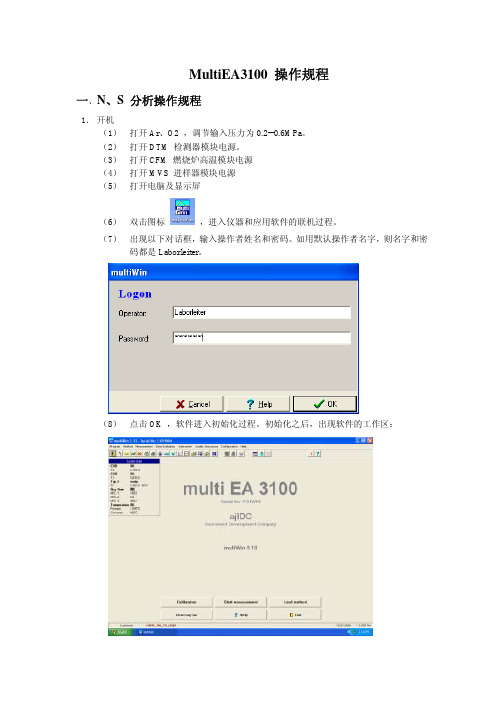
MultiEA3100 操作规程一、N、S 分析操作规程1.开机(1)打开Ar、O2 ,调节输入压力为0.2--0.6MPa。
(2)打开DTM 检测器模块电源。
(3)打开CFM 燃烧炉高温模块电源(4)打开MVS 进样器模块电源(5)打开电脑及显示屏(6)双击图标,进入仪器和应用软件的联机过程。
(7)出现以下对话框,输入操作者姓名和密码。
如用默认操作者名字,则名字和密码都是Laborleiter。
(8)点击OK ,软件进入初始化过程。
初始化之后,出现软件的工作区:(9)点击LOAD METHOD 按钮,双击测量N、S 的方法:hori_TN_TS_liqu.mth。
再点击OK ,完成调用方法过程(如果已调好当前方法,此步可略)。
(10)等待系统状态都显示OK 时,仪器已准备好测量条件。
(11)标样测量A.点击CALIBRATION 按钮,出现以下对话框:询问用户是否选择一个方法做标样?B.点击YES,又出现如下对话框:询问是否调用当前方法做标样?C.点击YES,进入校准参数输入界面:选择标准曲线的类型:●相同体积不同浓度(通常为默认)◎相同浓度不同体积输入浓度点的数量(Number of samples)如4个点。
输入TN,TS的测量重复次数和他们的浓度,如上所示。
其他校准参数可以默认,不需改变。
D.输完之后,点击MEASUREMENT 按钮,进入开始测量界面:E.点击START F2 开始测量。
弹出对话框:F.点击OK,进入注射样品的准备阶段,当出现以下对话框时:可以进样,进完之后按ENTER 键。
样品被带入燃烧炉中燃烧,并进入N,S 检测器检测。
G.再次出现以下对话框时,可以注射下一针样品。
H.根据提示,依次做完所有的标样后,软件会自动弹出以下界面:I.选择良好的标样点形成一条曲线,如果相关系数良好,点击跟方法连接按钮Link with method ,出现以下界面:通过比较当前和以前做的校准数据,点击接受ACCEPT V ALUE 按钮,把以前的数据替换掉。
sensor electronics corporation 3100 传输器操作手册说明书
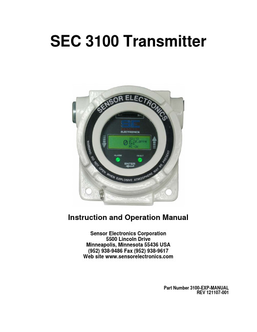
SEC 3100 TransmitterInstruction and Operation ManualSensor Electronics Corporation5500 Lincoln DriveMinneapolis, Minnesota 55436 USA(952) 938-9486 Fax (952) 938-9617Web site Part Number 3100-EXP-MANUALREV 121107-001Sensor Electronics CorporationSensor Electronics Corporation (SEC) designs and manufactures innovative fixed system gas detection quality and service are uncompromising. our products with a two-year warranty on all Gas Detect Individually designed maintenance pack ic customer needs. Service begins with Sensor Electronics Corporation (SEC) warrants anufactured by SEC to be free from defects in cluding rough handling, mechanical damage, alteration or repair. This Year 2000 ComplianceAll Sensor Electronics products have b d by Sensor Electronics to accuratelyequipment, for combustible gases, oxygen, carbon dioxide and toxic gases.CommitmentOur We back each of materials and workmanship. We offer technical support, user training and on-site service and maintenance of equipment to meet the needs of our customers.ion Serviceages are available for specif verification of the system installation that includes an initial system check and calibration. We then offer customer training programs (on-site and at factory) to insure that technical personnel fully understand operation and maintenance procedures. When on-the-spot assistance is required, service representatives are available to handle any questions or problems immediately.Warrantyproducts m workmanship and materials for a period of two (2) years from date of shipment from the factory. Any parts returned freight pre-paid to the factory and found defective within the warranty would be repaired or replaced, at SEC's option. SEC will return repaired or replaced equipment pre-paid lowest cost freight. This warranty does not apply to items, which by their nature are subject to deterioration or consumption in normal service. Such items may include: Fuses and Batteries.y abuse in Warranty is voided b warranty covers the full extent of SEC liability and SEC is not responsible for removal, replacement costs, local repair costs, transportation costs or contingent expenses incurred without prior written approval. Sensor Electronics Corporation's obligation under this warranty shall be limited to repair or replacement of any product that has been returned to Sensor Electronics Corporation for warranty consideration. This warranty is expressly in lieu of any and all other warranties expressed or implied, and all other obligations or liabilities on the part of Sensor Electronics Corporation including but not limited to, the fitness for a particular purpose. In no event shall Sensor Electronics Corporation be liable for direct, incidental, or consequential loss or damage of any kind connected with the use of it's products or failure to function or operate properly.een tested and are certifie process date/time and date/time related data from, into and between the 20th and 21st centuries. Sensor Electronics products neither contain nor create any logical or mathematical inconsistency, will not malfunction, and will not cease to function when processing date/time data. Please contact Sensor Electronics for further information.Table of Contents I. SPECIFICATIONSDESCRIPTIONII. GENERALIII. OPERATIONInstallation and StartupCodesFaultIV. MAGNETIC SWITCH OPERATIONV. FIGURESFigure 1 – Overall LayoutFigure 2 – SEC 3100 WiringFigure 3 – SEC Sensor Separation KitI. SPECIFICATIONSModel:SEC 3100 TransmitterFor use with:SEC Millenium and SEC Signature series infrared sensors and SEC 3000 Toxic and Oxygen gas sensors. Part Number: SEC 3100100Output (analog):4-20 mA (Source type), max. 1000 Ohm load at 24 VDC supply voltageOutput (digital):RS485 LAN (isolated)Output (relays):Three (3) Alarm, Low, Mid High. One (1) FaultRated for 8 Amps 30 VDC or 220VACDisplay:LCD (backlit)Construction:Epoxy coated aluminumClass 1, Division 1, Groups B, C and DOperating Temperature Rating:-40° to +158° F at 0 to 99% RH (non-condensing)(-20° to +70°C)Operating Voltage:24 VDCOperating range: 18 to 30 VDC measured at the detector headMax. Current Draw: (at 24 VDC with sensor)Average: 250 mAPeak: 500 mAInstallation Category: Cat. I, Pollution Degree 2II GENERAL DESCRIPTIONCONVENTIONSThe following conventions are used in this manual.!Warning StatementVDC (DC Voltage)SEC 3100The SEC 3100 transmitter is designed to be used with the SEC Millenium, SEC Signature infrared gas sensors or SEC 3000 toxic gas detectors. The SEC 3100 is a microprocessor based intelligent transmitter continuously monitoring information from the gas sensor. The LCD of the SEC 3100 displays the gas concentration and sensor status. The SEC 3100 has one (1) “Alarm” LED and one (1) “Status” LED. The SEC 3100 also has three (3) magnetic switches located around the circumference of the unit. This manual will describe the operation and use of the SEC 3100 transmitter.Features•Explosion Proof•Back lighted LCD Display•Low Cost•Plug and play toxic, oxygen and combustible gas sensors•Self-check system•4-20 mA ouput•RS-485 Interface (Isolated)•Optional alarm and fault relays•Non-intrusive programming•Non-intrusive calibration•Removable, non-volatile, time stamped data logging•Optional IS barrier•Digital communication link to SEC 3000 and SEC Millenium Gas Detectors•Multi port housing for easy installationIII. OPERATIONInstallation and Startup!Warning: The user shall be made aware that if the equipment is used in a manner not specified by the manufacturer, the protection provided by the equipment may be impaired.The first step in the installation process is to establish a mounting location for the SEC 3100 transmitter and gas sensor. Select a location that is typical of the atmosphere to be monitored or close to the anticipated source of a dangerous gas.It is very important that the SEC 3100 and gas sensor be properly located enabling it to provide maximum protection. The most effective number and placement of sensors vary depending on the conditions of the application. When determining where to locate gas sensors the following factors should be considered.•What are the characteristics of the gas that is to be detected? Is it lighter or heavier than air? If it is lighter than air the sensor should be placed above the potential gas leak. Place the sensor close to the floor for gases that are heavier than air. Note that air currents can cause a gas that is heavier than air torise. In addition, if the temperature of the gas is hotter than ambient air or mixed with gases that are lighter than air, it could also rise.•How rapidly will the gas diffuse into the ambient air? Select a location for the sensor that is close to the anticipated source of a gas leak.•Wind or ventilation characteristics of the immediate area must also be considered. Movement of air may cause gas to accumulate more heavily in one area than in another. The detector should be placed in the areas where the most concentrated accumulation of gas is anticipated. For outdoor applications with strong wind conditions, it may require the sensors to be mounted closer together and on the down wind side, to the anticipated area of a gas leak. Also take into consideration for indoor applications, the fact that many ventilation systems do not operate continuously.•The sensor should be accessible for maintenance.•Excessive heat or vibration can cause premature failure of any electronic device and should be avoided if possible.•Follow all national and local installation codes and practices.The SEC 3100 has three (3) ¾” NPT threaded connectors for mounting and wiring the sensor and transmitter into a permanent installation.Field wiring connections are made on the backside of the SEC 3100 printed circuit board (PCB). For wiring details refer to Figure 2 in the back of the manual.Power wire sizing:0 to 500 feet, recommended wire gauge size 16 AWG501 to 1000 feet, recommended wire gauge size 14 AWGShielded cable is recommended. Wiring should be installed in medal conduit with no other cabling in the same conduit.Warm-upWhen power is applied to the SEC 3100, it enters a one (1) minute warm-up mode. The output current will be 0.8 mA during the warm up time period. At the end of the warm-up period with no faults present, the SEC 3100 automatically enters the normal operating mode (4.0 mA with no gas present). If a fault is present after warm-up, the detector current output and LCD will indicate a fault. The Fault LED will also indicate the fault.NormalIn the normal operating mode, the 4 to 20 mA signal levels correspond to the detected gas concentration. The transmitter continuously checks for and displays system faults or initiation of calibration and automatically changes to the appropriate mode.The 4 to 20 mA output of the SEC 3100 sensor is a non-isolated current source.Current Output and Corresponding StatusOnce the fault is cleared the SEC 3100 will atomatically resume normal operation.Flash Rate Output Current Unit StatusLabelPossible Problem1 4-20ma Unit Running Unit is measuring gas and adjusting 4-20ma output accordingly.2 2.2ma Unit Zero Calibrating Unit going through its zero calibration procedure.3 2.0ma Unit Spanning Unit going through its spanning procedure.5 0.8ma Unit Warm-up Only for one minute after unit power-up6 0.0ma Power-up Fault Hard Fault (refer to gas sensor manual)7 1.6maCalibrationFault 1. AttemptUnit Span with no gas 2. AttemptUnit Zero with gas8 NA NA Currently Not Used9 0.0ma Unit Fault Hard Fault (refer to gas sensor manual)10 1.0ma Optics Fault Clean sensor’s windows11 1.2ma Zero Drift Fault Hard Fault (refer to gas sensor manual)12 0.0maConfigurationFault HardFault (refer to gas sensor manual)16 0.2ma Reference Channel Fault Hard Fault (refer to gas sensor manual)17 0.4ma Active Channel Fault Hard Fault or Unit Zero with gasIV. MAGNETIC SWITCH OPERATIONThe SEC 3100 has three (3) magnetic switch pickups on the Display PCB. The picture below shows the location of the magnetic switches labeled UP, DOWN and ENTER. Placing a magnet in close proximity to one of the switches will cause the following operations to occur.Switch Operation ENTER Enter Menu Mode, Selects a menu to Enter UP Moves up through Menu selections DOWN Moves down through Menu selectionsFor further details on gas sensor calibration refer to the appropriate SEC sensor instruction manual.The LCD contrast potentiometer, (POT1) is located under the protective faceplate shown above on the front side (LCD side) of PCB to the left of the LCD.Gas Sensor Port (1 x ¾h)SEC 3000SEC MilleniumMagnetic Switch (3)Field Wiring Port (2 x ¾h )¾Power¾4-20 mA¾RS485 (MODBUS) ¾Alarm RelaysFault LED Green OK Memory Data CardSlotRed FaultLCD Display:Real Time Status Gas TypeGas Concentration Fault Identification RangeID NumberMemory Card Status Interactive MenusCalibration Relay Programming ID & Zone NumberMounting holes (2)Alarm LED Green OK Yellow Low Alarm Orange Mid Alarm Red High AlarmV. MENU OPERATIONInital Power Up Sequence of the SEC 3100In normal operating mode. Actual gas concentration will be displayed to the left of ID #, Range, Gas Type, MC (Memory Card) status.Selecting Enter when the SEC 3100 in in normal operating mode will advance to the following display:Selecting Enter will allow the operator to safely remove the Memory Card. Arrow DownEntering the INFO menu will display the following screenSelecting Enter at UNIT INFO displays the following: SN is the SEC 3100 serial number. VER is the SEC 3100 software version number. Selecting Enter againwill return the display to the main info menu.The following are the other INFO sub displays and descriptions. To return back to the main INFO menu from the sub menus, select Enter.Sensor Status Menu TYP: Sensor type (0.0 is a SEC 3000, 32.0 is SEC Millenium)SN: Sensor serial number. VER: Version of sensor software. CAL: Calibration date of sensor.Sensor Status Menu RBR COUNT : SEC information ICE COUNT : SEC information. BATTERY : Displays status of SEC 3100 batteryMain Menu and Sub MenusEnterUsed to calibrate the gas sensor.Down ArrowAlarm MenuUsed to setalarm level set points andparameters.Down ArrowRelay MenuFor setting alarm relay On & Off delay &Energized states.Down ArrowNetwork MenuDown ArrowHide Menu Hide is used toblank thedisplay up tolow alarm settingDown ArrowSelf Test MenuGenerates asignal on the display, RS485 4-20 mADown MenuDate Time MenuDown ArrowExit back tonormalCalibration MenuEnter Using the Up and Down arrows allows the operator to move the cursor (*) to select a function.To Zero the sensor apply clean air (N2 for an oxygen sensor) and select enter. The following will be displayed.Then the following will be displayed.Once complete the following will be displayed. The sensor has been successfully zeroed.Arrow down to CAL. VAL to verify the span gas calibration value matches the value of the span gas calibration on hand. If not, select Enter and the following screen will appear.Using the Up and Down arrows will allow the operator to change the calibration gas value of the sensor to match the calibration gas used to span the sensor. Once the correct value is displayed select Enter and the sensor will be uploaded with the new calibration gas value.To Span the sensor with calibration gas use the Up and Down arrows to select the following display.Apply span gas to the sensor for the appropriate amount of time in order for the sensor to stabilize. The gas reading is displayed to the right of ZERO. Once stable select Enter. This will go the display:If calibration span gas is still present the display will read:Apply clean air to the sensor to reduce this reading.The display will advance to the following:This completes the calibration and the device can be put back into the normal operating mode.Arrow Down toEnterEnter again and the SEC 3100 returns to normal operation.Alarm MenuEnterEnterSelect the Alarm Relay (LOW, MID, HI) using the down arrow. Once the cursor is on the alarm relay you wish to configure, hold the magnet over Enter. The example LOW will be used. The same operations can be used to set the MID or HI relays.Selecting Enter will display the following screen allowing the alarm set point to beprogrammed. Using the Up and Down arrows will change the set point. Once the correct set point is displayed select Enter and the new value will be accepted.Arrow DownSelecting Enter will allow the operator to change the operation of the relay operation from Non-Latching (NO) to Latching (YES).Arrow DownSelecting Enter will allow the operator to change the operation of the relay operation from Active HI to Active LOW. HI activates the relay on a rising alarm level. LOW actives the relay when the alarm threshold falls below the alarm set point. Once the correct operation is selected, use the Down arrow to advance to the next menu item.Arrow DownSelecting Exit will advance to the next menu.This menu will allow the operator to select another relay to program. Or select Exit and the next display will be:Selecting Enter on this display will put the SEC 3100 back into normal operation.Relay MenuSelecting Enter will advance to the following menu.Arrow down to the next screen will beSelect the Alarm Relay (LOW, MID, HI, FAULT) that is to be configured using the down arrow. Once the cursor is on the correct alarm relay, hold the magnet over Enter. The example LOW will be used. The same operations can be used to set the MID, HI, or FAULT relays.Select EnterSelect EnterUsing the Up and Down arrows the operator can change the ON delay time for the relay to actuate after the alarm threshold has been exceeded. The time is measured in seconds (0-255). Once the correct time is displayed select Enter to accept the new value. Then Exit the menu and proceed on to the next selection. In this example the Low alarm relay will actuate 30 seconds after the Low set point is exceeded.Select EnterSelect EnterUsing the Up and Down arrows the operator can change the OFF delay time for the relay to turn OFF after the reading has decreased below the alarm point threshold. The time is measured in seconds (0-255). Once the correct time is displayed select Enter to accept the new value. Then Exit the menu and proceed on to the next selection.In this example the Low alarm relay will stay energized for 60 seconds after the alarm has cleared.Arrow DownSelecting Enter will allow the operator to change the operation of the relay coil from normally de-energized (ENERGIZED NO) to normally energized (ENERGIZED YES). Once the correct operation is selected, use the Down arrow to advance to the EXIT menu. Select Enter to go back to the Relay MenuThis menu will allow the operator to select another relay to program. Or select Exit and the next display will be:Arrow Down to ExitEnterSelecting Enter will return the SEC 3100 into normal operation.Network MenuSelect EnterSelect Enter to change the Zone number of the SEC 3100.Use the Up and Down Arrows change the Zone number (0-255). Once the correct Zone number is displayed select Enter.Arrow Down to ID. To change the ID number select Enter. Use the Up and Down Arrows to change the ID number (0-255). Once the correct ID number is displayed select Enter.Arrow Down to Online.Using Enter the operator can toggle between Online YES and Online NO. Online YES turns on the MODUS RS485 communication. Online NO turns the MODBUS RS485 communication off.Arrow Down to ExitEnterHide MenuUsing Enter the operator can toggle between Hide YES and Hide NO.The Hide function allows the operator to not display the gas reading until the Low Alarm threshold is exceeded. All outputs will function as normal when the Hide mode selected to YES.Self Test MenuSelecting Enter for the Self Test will make the sensor generate a 4-20 mA input into the SEC 3100 from 4 mA to 20 mA (0-fullscale). In the self test mode the SEC 3100 outputs are fully functional. The SEC 3100 will display the rising gas level, the 4-20 mA output will increase to 20 mA, the relays will actuate and the RS485 information will be transmitted to the control system. The following screen will be displayedOnce the unit reaches full scale the SEC 3100 automatically returns to normal.Time Date MenuEntering this menu will allow the operator to set the time and date of the SEC 3100 real time clock.Selecting Enter will locate a cursor (*) above the number allowing the operator to use the Up Down arrows to increase or decrease the numbers. Once the correct number is displayed, select Enter with the magnet and the cursor will advance to the next number.Date is MM/DD/YYYY. Time is HH/MM/SS. Below is an example.Enter from above display.Arrow Up one number.EnterContinue with the sequence until the correct date appears. Then select Enter and the following will be displayed.programmed, select Enter and arrow down to Exit.Select EnterSelecting Enter again will return the SEC 3100 to normal operation.Diagnostics MenuThe Diagnostics Menu will allow the operator to enter the Locator Mode and Toggle Relays on and off to verify operation.Selecting Enter will display the following:The Locator function is normally generated by the SEC 3500 operator interface. It can be used at the SEC 3100 to function as a lamp test. Selecting Enter will turn the Locator on.The Alarm and Fault LEDs will flash red and green alternately.Selecting Enter again will turn the Locator function off.Arrow Down to Toggle Relays (manual relay control)Selecting Enter will display the following:Select the Alarm Relay (LOW, MID, HI, FAULT) that is to be configured using the down arrow. Once the cursor is on the correct alarm relay, hold the magnet over Enter. The example LOW will be used. The same operations can be used to manually control the MID, HI, or FAULT relays.Selecting Enter will manually turn on the relay, selecting Enter again will turn off the relay.Reset Relays MenuThe Reset Reset relays Menu will allow the operator to reset latched relays.Latched relays will be indicated by a blue flashing Alarm LED. Select Enter and any latched relays will be reset.V. FIGURESFigure 1 – Overall LayoutFigure 2 – SEC 3100 WiringFigure 3 – SEC Sensor Separation KitFigure 4 – Mounting SEC 3100 and SEC Millenium Figure 5 – Mounting SEC 3100 and SEC 3000Relay ID & Zone NumberMagnetic Switch (3)Fault LED Green OK Red FaultAlarm LED OK Low Alarm Mid AlarmTB 3(1) WHITE TB 2(1) 4-20 mA ANALOG OUTPUT (12) LOW ALARM N.C.(11) LOW ALARM COMMON RELAY WIRINGFIGURE 4FIGURE 5SEC 3100 – SEC 3000 Mounting。
3100-Avant遗传分析仪操作规程及注意事项
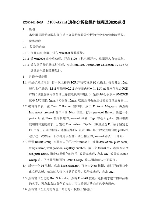
ZX/C-001-20053100-Avant遗传分析仪操作规程及注意事项1 概述本仪器是用于核酸和蛋白质序列分析和片段分析的专业毛细管电泳设备。
2 操作程序2.1 仪器的启动2.1.1 打开Dell电脑,进入win2000操作系统。
2.1.2 等win2000完全启动后,开启3100主机电源开关,仪器进入自检状态。
2.1.3 等仪器的绿色状态灯亮后,双击Run 3100-Avant Data Collection(V2.0)快捷键进入数据收集软件。
3 片段分析步骤3.1 样品扩增结束后,将一次上样的PCR产物转移到96孔板上,每孔各加10ul。
每孔上样量是:8.8μl甲酰胺+0.2μl分子量内标+(1-1.5)μl各座位混合PCR 产物(试剂盒或标准品的上样按照说明书进行),先将96孔板放入9700PCR 仪中95℃变性5min,4℃保存10min,取出后将板放到仪器的自动进样器上。
3.2 编辑样品表。
在Data Collection 窗口中,点击Protocol Magager,再点击Instrument protocol窗口中的New按钮,打开protocol Editor,新建一个protocol,在Name栏为新建的protocol 命名,Type中选Regular,然后根据使用的试剂的要求,分别在Run module、DyeSet(微卫星选D,亲子鉴定选F)中选出正确的程序,选择完毕后,点击OK。
每一种荧光组合的protocol 运行过一次以后,下次再用该组合,调出相应的protocol确认一下即可。
3.3 设置Result Group。
在其窗口的第一个format中,选择date of run, plate name,sample name, well position, capillary number;第二个format中,选择date of run, plate name,指定结果保存的路径,设置完成后,点击OK。
3100型定义目的开关器产品说明书
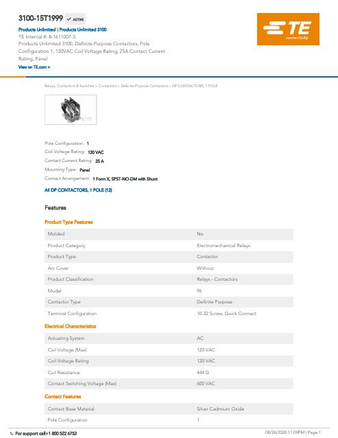
3100-15T1999Products Unlimited 3100, Definite Purpose Contactors, Pole Configuration 1, 120VACCoil Voltage Rating, 25A Contact Current Rating, Panel08/26/2020 11:09PM | Page 1 For support call+1 800 522 6752Relays, Contactors & Switches>Contactors>Definite Purpose Contactors>DP CONTACTORS, 1 POLEContact Arrangement: 1 Form X, SPST-NO-DM with ShuntMounting Type:PanelContact Current Rating:25 ACoil Voltage Rating:120 VACPole Configuration:1All DP CONTACTORS, 1 POLE (12)FeaturesProduct Type FeaturesMolded NoProduct Category Electromechanical RelaysProduct Type ContactorArc Cover WithoutProduct Classification Relays - ContactorsModel96Contactor Type Definite PurposeTerminal Configuration10-32 Screw, Quick ConnectElectrical CharacteristicsActuating System ACCoil Voltage (Max)120 VACCoil Voltage Rating120 VACCoil Resistance444 ΩContact Switching Voltage (Max)600 VACContact FeaturesContact Base Material Silver Cadmium OxidePole Configuration1Contact Current Rating25 A3100-15T1999 ACTIVEProducts UnlimitedTE Internal #:8-1611007-5Products Unlimited 3100, Definite Purpose Contactors, PoleConfiguration 1, 120VAC Coil Voltage Rating, 25A Contact CurrentRating, PanelView on >Products Unlimited 3100|Pole Configuration1Contact Current Rating25 AContact Arrangement 1 Form X, SPST-NO-DM with ShuntTermination FeaturesCoil Termination Quick ConnectMechanical AttachmentMounting Plate WithMounting Type PanelDimensionsWire Size 1.31 – 8.37 mm²Industry StandardsUL Flammability Rating UL 94V-0Agency Approval CSA Certified, SEMKO Certified, ULRecognizedPackaging FeaturesPackaging Method Loose PieceOtherComment Stranding must be split for 8 AWG wire.Torque25 in-lbsProduct ComplianceFor compliance documentation, visit the product page on >EU RoHS Directive 2011/65/EU Compliant with ExemptionsEU ELV Directive 2000/53/EC Not CompliantChina RoHS 2 Directive MIIT Order No 32, 2016Restricted Materials Above ThresholdEU REACH Regulation (EC) No. 1907/2006Current ECHA Candidate List: JUN 2020(209)Candidate List Declared Against: JAN 2019(197)Does not contain REACH SVHCHalogen Content Not Yet Reviewed for halogen contentSolder Process Capability Not applicable for solder process capabilityProduct Compliance DisclaimerThis information is provided based on reasonable inquiry of our suppliers and represents our current actual knowledgebased on the information they provided. This information is subject to change. The part numbers that TE has identified asEU RoHS compliant have a maximum concentration of 0.1% by weight in homogenous materials for lead, hexavalent08/26/2020 11:09PM | Page 2 For support call+1 800 522 675208/26/2020 11:09PM | Page 3For support call+1 800 522 6752EU RoHS compliant have a maximum concentration of 0.1% by weight in homogenous materials for lead, hexavalent chromium, mercury, PBB, PBDE, DBP, BBP, DEHP, DIBP, and 0.01% for cadmium, or qualify for an exemption to these limits as defined in the Annexes of Directive 2011/65/EU (RoHS2). Finished electrical and electronic equipment products will be CE marked as required by Directive 2011/65/EU. Components may not be CE marked.Additionally, the part numbers that TE has identified as EU ELV compliant have a maximum concentration of 0.1% by weight in homogenous materials for lead, hexavalent chromium, and mercury, and 0.01% for cadmium, or qualify for an exemption to these limits as defined in the Annexes of Directive 2000/53/EC (ELV). Regarding the REACH Regulations, TE’s information on SVHC in articles for this part number is still based on the European Chemical Agency (ECHA) ‘Guidance on requirements for substances in articles’(Version: 2, April 2011), applying the 0.1% weight on weight concentration threshold at the finished product level. TE is aware of the European Court of Justice ruling of September 10th, 2015 also known as O5A (Once An Article Always An Article) stating that, in case of ‘complex object’, the threshold for a SVHC must be applied to both the product as a whole and simultaneously to each of the articles forming part of its composition. TE has evaluated this ruling based on the new ECHA “Guidance on requirements for substances in articles” (June 2017, version 4.0) and will be updating its statements accordingly.TE Model / Part #5-1437595-9TRD11H10WL=ROCKER GOLD ON OFFTE Model / Part #2-1393117-4KUP-11A25-120=KUTE Model / Part #62718-1FASTON .250 FLAG REC 22-18 AWG BRTE Model / Part #6-1393118-0KUP-5A15-24=KUDefinite Purpose Contactors(80)TE Model / Part #175022-1PL EX MKII 250 REC 18-14AWG PTBRTE Model / Part #CAT-P592-SP118PIDG SPADE TONGUE TERMINALSTE Model / Part #CAT-P592-R472A PIDG RING TONGUE TERMINALSCompatible PartsAlso in the Series Products Unlimited 3100Customers Also BoughtDocumentsCAD Files3D PDF3D3D PDF3DCustomer View ModelENG_CVM_CVM_8-1611007-5_D.2d_dxf.zipEnglishCustomer View ModelENG_CVM_CVM_8-1611007-5_D.3d_igs.zipEnglishCustomer View ModelENG_CVM_CVM_8-1611007-5_D.3d_stp.zipEnglishBy downloading the CAD file I accept and agree to the of use.Terms and ConditionsDatasheets & Catalog PagesModel 96 - 3100 Definite Purpose Contactor 1- or 2-pole, 20-40 FLA AC CoilEnglishIndustrial Relays Quick Reference GuideEnglish08/26/2020 11:09PM | Page 4 For support call+1 800 522 6752。
NTRON3100氧气分析仪 中文操作手册
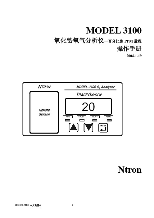
MODEL 3100 氧化锆氧气分析仪—百分比到PPM量程操作手册2004-1-19Ntron目录安全提示 (3)第一部分操作原理1.1概括 (4)1.2特征 (4)1.3系统组成 (5)1.4 分析仪输入与输出 (7)1.5 控制面板 (8)第二部分 1100分析仪操作2.1安装 (10)2.1.1 分析仪的安装位置 (10)2.1.2 远传传感器的安装 (11)2.1.3 分析仪安装 (11)2.2开始 (15)2.2.1 通电 (15)2.2.2 校准 (15)2.2.3 报警设置 (15)第三部分操作形式3.1系统机构 (16)3.2 用户形式 (16)3.3 系统模式 (17)第四部分维护 (19)4.1系统设置 (19)4.2定期维护表格 (28)4.3 发现并维修故障 (28)安全提示:安装或操作之前请详细阅读操作手册。
在没有完全明白型号3100的特征和功能之前而进行操作,可能会造成危险。
⏹气体加压时,使用保护眼罩和遵守安全的程序。
⏹测量气体要在相同压力和流速下校准。
⏹确保在使用之前已经校准仪器。
⏹3100分析仪外壳不具有防水功能,避免放置在液面,潮湿等地方。
⏹不要放置在易燃或高温环境的地方。
⏹3100分析仪不具有防爆等级或本安型,避免放置在有易燃气体或水蒸汽的地方。
⏹确保分析仪的操作温度,不要置于高温的表面,不要阻塞通风口。
第一部分操作原理1.1概括Ntron 公司的3100系列分析仪,它提供了在微氧测量和控制运用中的有效解决。
它针对于精确测量百分比范围氧而设计的分析仪。
氧气精确测量从0.1PPM到100%。
3100分析仪内置Ntron公司的远控传感器机箱(RSM),传感器机箱的主体部分是Ntron公司独有的“氧化锆传感器”。
氧化锆传感器是一个具有可靠性和反映快功能的固态装置,由于它是固态,所以不受干燥环境影响,在极冷的冷藏库下不受损坏。
3100分析仪的全图:1.2 特征型号3100分析仪为嵌板或控制台的装置。
ESEC3100中文操作手册
Basic Information (Chinese Simplified) 基本信息
Object No./Index Released Date July 2004
Content Reference
Copyright 版权
© by ESEC SA, Switzerland, 2004 没有出版者的预先写作许可,这出版物的部份不能被再生产,被存放,或被传送,于任何检索系统。
Imprint
Index: Last change: Concept: Translator: Checked: Approved: Original Language: Manual Feedback: ESEC Information:
01 July 2004 CSE - Infineon Shuzhou CZG TWE/VCH D&T English vch@
© by ESEC
v
1. 基本操作
基本操作
1.1 一般概念
WB3100为生产操作员提供了友善和舒适的支持。鼠标用来进入图形用户界面(GUI)的 菜单和命令,键盘区提供一些快捷键,方便生产中常用到的一些功能,如弹匣的处理 ,生产设定(金线和磁嘴),indexer和焊线功能。 注意:视登录的用户水平而定,不是所有的菜单和功能都可涉及。
内容目录
1 1.1 1.2 1.2.1 1.2.2 1.2.3 1.2.4 1.3 1.4 1.5 1.6 1.6.1 1.6.2 1.6.3 1.6.4 1.6.5 1.7 1.7.1 1.7.2 1.7.3 1.7.4 1.7.5 1.7.6 1.7.7 1.7.8 1.8 1.8.1 1.8.2
ESEC K.K. 2-17-8 Nagata-cho Chiyoda-ku Tokyo 100-0014 / Japan Phone +81 – 3 3503 4305 Fax +81 – 3 3503 4304
迪纳尔2100 3100系列传输带配件安装指南说明书
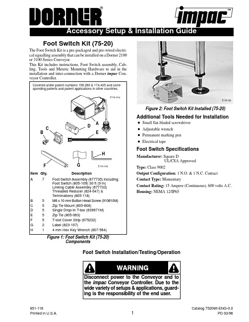
Foot Switch Kit (75-20)The Foot Switch Kit is a pre-packaged and pre-wired electri-cal signalling assembly that can be installed on a Dorner 2100or 3100 Series Conveyor.This Kit includes instructions, Foot Switch assembly, Cab-ling, Tools and Meteric Mounting Hardware to aid in theinstallation and inter-connection with a Dornerveyor Controller.Covered under patent numbers 156,260 & 174,435 and corre-sponding patents and patent applications in other countries.E116–02Figure 2: Foot Switch Kit Installed (75-20)Additional Tools Needed for InstallationD Small flat-bladed screwdriverD Adjustable wrenchD Permanent marking penD Electrical tapeFoot Switch SpecificationsManufacturer: Square DUL/CSA ApprovedType: Class 9002Output Configuration: 1 N.O. & 1 N.C. ContactContact Type: MomentaryContact Rating: 15 Ampere (Continuous), 600 volts A.C.Housing: NEMA 12/IP651.Verify all kit parts are present.2.Refer to Figure 2 and select the desired location forplacing the Foot Switch (A) on the floorTo facilitate Cable routing, place the Foot Switch on same side of conveyor that impacmounted.3.Route the cable from the Foot Switch to theConveyor Controller.a.Cable routing should not run near any movingconveyor parts, where it could possibly be damagedor cause damage to the conveyor.b.The conveyor T-slots or optional 6 ft (1829 mm) or12.5-ft (3810 mm) Wire Troughs (Dorner #75-85-6 or#75-85-12) can be used to route wiring cable. Foradditional Wire Trough information, refer to separateSetup & Installation Guide (not provided).Figure 3: T-slot Cover Strip Mounting DetailE116–03bTo route Cable over a previously mountedFigure 4: Zip Tie Mounting Detail E116–04bIMPACConveyorControllerNOTE:The following connections are for a sample application that requires the conveyor to run when Foot Switch is depressed. Refer to the impac Application Guide for details on other application designs and wiring con-nections.In addition, when inserting a wire into a Terminal Block termination, be sure to tightly anchor the wire by tighten-ing the screw and double-check that wire has been fully secured by giving it a light tug.Figure 7: Sample Foot Switch to impacWiring ConnectionsBrown Wire #4LocknutimpacMotorGreen #3Brown #4White #5Red #1Black #2E116–07aContacts are shown when Foot Switch is not depressed.E116–07b7.Test operation as follows:a.Be sure the impac On/Off Switch is OFF and thatConveyor is ready to run. Then, begin the test byre-connecting power to theturn on power at this time. Keep theSwitch OFF.b.Operation of the Conveyor may vary depending onthe chosen application. Consult theGuide for your particular application.c.Shown here is an application using a Foot Switchto start and stop a Conveyor (Figure 8).d.Turn impac On/Off Switch to ON.e.Test Foot Switch on/off operation by depressing andreleasing the foot pedal. When Pedal is depressed,Conveyor should run and when Pedal is released,Conveyor should stop running.Dorner Mfg. Corp. reserves the right to change ordiscontinue products without notice. All products and。
3100 宏量移液器 操作说明书
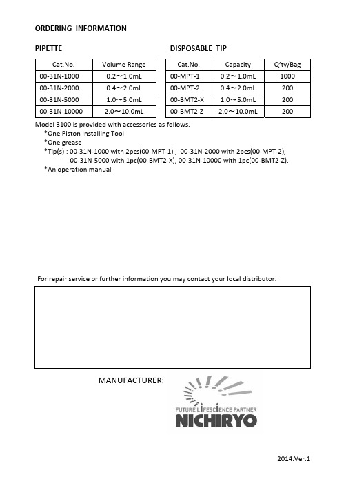
ORDERING INFORMATIONPIPETTE DISPOSABLE TIPCat.No. Volume Range Cat.No. Capacity Q’ty/Bag 00‐31N‐1000 0.2~1.0mL 00‐MPT‐1 0.2~1.0mL 100000‐31N‐2000 0.4~2.0mL 00‐MPT‐2 0.4~2.0mL 20000‐31N‐5000 1.0~5.0mL 00‐BMT2‐X 1.0~5.0mL 20000‐31N‐10000 2.0~10.0mL 00‐BMT2‐Z 2.0~10.0mL 200Model 3100 is provided with accessories as follows.*One Piston Installing Tool*One grease*Tip(s) : 00‐31N‐1000 with 2pcs(00‐MPT‐1) , 00‐31N‐2000 with 2pcs(00‐MPT‐2), 00‐31N‐5000 with 1pc(00‐BMT2‐X), 00‐31N‐10000 with 1pc(00‐BMT2‐Z).*An operation manualFor repair service or further information you may contact your local distributor:MANUFACTURER:2014.Ver.1CERTIFIED ISO9001● Thank you very much for purchasing MODEL 3100 ● Please read this manual carefully before using.Always Pursuing Originality Since 194421L4lm35OOCKLMODEL 3100MACROPIPETTEFEATURES•Excellent accuracy and precision.•Four different volume ranges, 1mL, 2mL, 5mL and 10mL.•Volume of pipetting is easily changed and fixed.•Light design permits easy handling without fatigue.SPECIFICATIONSAccuracy: ± 1.0% Reproducibility Precision: ≤ 1.0%Cat.No. Volume Range Increments00‐31N‐1000 0.2~1.0mL 0.1mL00‐31N‐2000 0.4~2.0mL 0.1mL00‐31N‐5000 1.0~5.0mL 0.5mL00‐31N‐10000 2.0~10.0mL 0.5mLOPERATING PROCEDURES1. Loosen the lock nut and turn the push button until the yellow cross‐line corresponds to the desired volume indicated by the volume scale, then lock by tightening the lock nut.2. Attach a disposable tip firmly onto the syringe nozzle.3. Depress thepush button several times to ensure smooth movement of the piston. Push the push button to the first stop. (Fig. 1, B)4. Place the disposable tip into liquid to a depth of 3 to 4mm.5. Slowly return the push button to its original “up” position. (Fig. 1, A) The sample will be drawn into the tip. The push button should be carefully released so not to flush the liquid into the tip of the pipette, especially for 5mL and 10mL model.6. Touch the tip to the inside wall of the receiving vessel.7. Press the push button again to the first stop to dispense most of the liquid.Wait one second with the push button Held in this position, then continue to push the push button to its limit(Fig. 1, C).This forces out the last remaining liquid from the tip. Keep the knob fully depressed until the tip is removed from the receiving vessel. Remove used tip from the pipette.ABCFig.1REPLACEMENT OF PARTS1. PUSH BUTTON – It is easily removed by pulling it off the push button.2. SYRINGE – Turn it counterclockwise to remove from the syringe connector. (Fig. 3)3. PISTON – After removal of the syringe, keep the push button fully depressed, and push a pin by the probe of the piston installing tool. To install thepiston, push the pin by opposite side of the tool. (Fig. 4)Note:The piston should be lubricated with a small amount of silicone grease provided after certain interval or after cleaning of the piston when contaminated.Syringe Connector Plunger PinPiston InstallingTool(to remove)(to install)Piston Fig.4PARTS AND MATERIALS①Push Button (Polypropylene)②Shaft(Stainless Steel)③Lock Nut (Alumite platedAluminium)④Volume Scale (Polymethylpentene)⑤Body (Polypropylene)⑥Syringe Connector (Polypropylene)⑦Piston(Fluoroplastic)⑧Syringe (Polypropylene)⑨Disposable Tip (Polypropylene)①②③④⑤⑥⑦⑧⑨⑩41235mlFig.2Syringe NozzleSyringeSyringe ConnectorFig.3。
ESEC3100中文操作手册

ESEC (Philippines) G/F Plaza B, Northgate Ave. Northgate Cyberzone Filinvest Corporate City, Alabang 1780 Muntinlupa / Philippines Phone +632 876 5130 Fax +632 876 5133
ESEC Customer Support
ESEC Hinterbergstrasse 32 P.O. Box 5503 CH-6330 Cham / Switzerland Phone +41 41 749 51 11 Fax +41 41 741 64 84
ESEC (Europe) Hinterbergstrasse 28 P.O. Box 5503 CH-6330 Cham / Switzerland Phone +41 41 749 55 00 Fax +41 41 749 55 55
© by ESEC
iii
1.8.3 参数记录………………………………….…………………………………………………………1-28 1.9 诊断信息………………………………….…………………………………………………………1-29 1.9.1 概述………………………………….………………………………………………………………1-29 1.9.2 通知……………………………………….…………………………………………………………1-30 1.9.3 警告………………………………….………………………………………………………………1-31 1.9.4 失败………………………………….………………………………………………………………1-32 1.9.5 报警………………………………….………………………………………………………………1-33 1.10 基本操作………………………………….…………………………………………………………1-34 1.10.1 更换金线线轴………………………………….……………………………………………………1-34 1.10.2 更换磁嘴………………………………….…………………………………………………………1-36 1.10.3 穿金线………………………………….……………………………………………………………1-39 1.10.4 产生线尾…………………………….………………………………………………………………1-40 1.10.5 照相机/ 磁嘴微偏移量(CCO)…………………………………………………………………… 1-41
电子牙刷3100系列:3100系列电子牙刷说明书

3100 seriesSonic technologyPressure sensorQuadPacer and SmarTimerSlim ergonomic designHX3671/11Goodbye manual toothbrush. Hello Sonictechnology.Up to 3 x better plaque removal*Sonic technology combined with our brush action gently removes plaque up to3 x better* than a manual toothbrush.Provides superior cleanOur unique technology brings you a powerful yet gentle cleanUp to 3 x better plaque removal vs. a manual toothbrush*Protects your gumsBuilt-in pressure sensor protects your teeth and gumsOptimise your brushingOptimise your brushing with SmarTimer and QuadPacerDesigned around youAlways know when to replace your brush headsErgonomic design makes the toothbrush easy to hold and use14 day long-lasting battery lifeUse less. Reuse moreEasy transition to SonicareEasy-Start to ease the transitionHighlightsAdvanced Sonic TechnologyPowerful bristle vibrations drive microbubbles deep between your teeth and along your gum line for a refreshing experience. You will get two months' worth of manual brushing in just 2minutes.** 31,000 brush strokes per minute gently clean your teeth, break up plaque and sweep it away for an exceptional daily clean.Removes plaque 3 x better*The Sonicare electric toothbrush with advanced sonic technology is clinically proven to remove plaque up to 3 x better* than a manualtoothbrush. It removes plaque from your teeth and along the gum line while protecting your gums.Protects your gumsBuilt-in pressure sensor automatically detects the pressure you apply, warns you and reduces the toothbrush vibrations automatically to helpprotect your gums. The toothbrush will make a pulsing sound as a reminder to ease off the pressure. 7 out of 10 people found this feature helped them become better brushers.SmartTimer and QuadPacer2 minute SmartTimer and 30 secondQuadPacer guide you to brush for therecommended time in all areas of your mouth to ensure a complete clean.Designed around youSlim, lightweight and ergonomic design makes the toothbrush easy to hold and use so that you get an amazing clean without any strain.BrushSync replacement reminderAll brush heads wear out over time, so you'll want to keep an eye on yours to make sure you're still getting a great clean. OurBrushSync technology tracks how long you'vebeen using your brush head for and how hard you've been brushing. The BrushSyncreplacement reminder on your handle and a short beep remind you when it's time to replace it.Easy-StartOur Easy-Start programme gives you theoption of a gradual, gentle increase in brushing power the first 14 times you use your new toothbrush.Long-lasting battery lifeBattery life lasts up to 14 days so you can go long periods without charging.Goodbye adapter. Hello USB.Power adapters may seem small, but added together, their plastic makes a huge impact on the environment. By switching to a USB charger in our Philips Sonicare 1000-4000Series alone, we use up to 189,210 kg less plastic every year. That's powerful, right?SpecificationsModesClean: For exceptional everyday cleaning Items includedHandle: 1 3100 SeriesBrush head: 1 C1 ProResults standard Charger: 1Design and finishingColour: Sugar roseCleaning performancePerformance: Removes up to 3 x more plaque* Pressure feedback: Vibrates handle to alert userTimer: Quadpacer and Smartimer Smart sensor technologyBrushSync Replacement Reminder: Alwaysknow when to, replace brush headsPressure sensor: Alerts when brushing toohardEase of useHandle: Slim ergonomic designBattery indicator: Light shows battery statusBrush head system: Easy click-on brushheadsBrushSync Replacement Reminder:Replacement reminder, Always know when to,replace brush heads, Reminder icon lights up,to always ensure best resultsT echnical specificationsBattery: RechargeableBattery type: Lithium IONOperating time (full to empty): 14 days*****PowerVoltage: DC5VServiceWarranty: 2-year limited warranty* vs manual toothbrush for healthier teeth and gums* Individual results may vary* * Data on file* **** based on two periods of two-minute brushings perday on standard mode© 2021 Koninklijke Philips N.V.All Rights reserved.Specifications are subject to change without notice. Trademarks are the property of Koninklijke Philips N.V. or their respective owners.Issue date 2021‑10‑05 Version: 10.0.1EAN: 08 71010 39855 63 。
Entech3100罐清洗仪简明操作指南
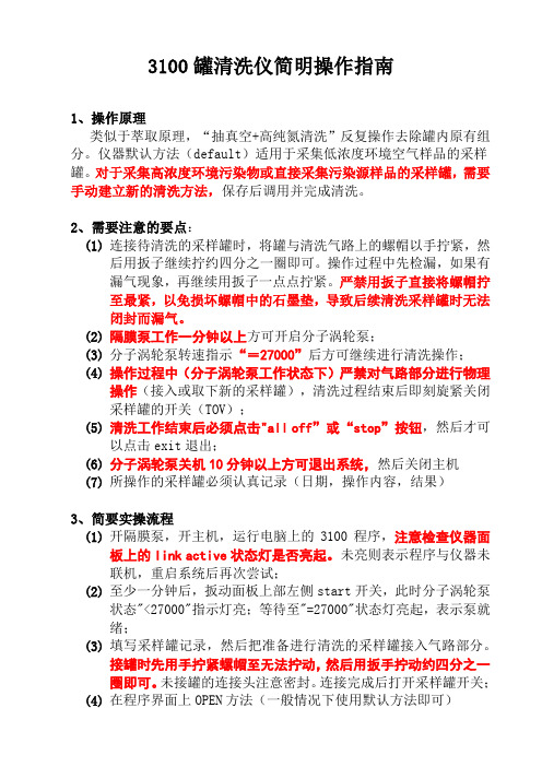
3100罐清洗仪简明操作指南1、操作原理类似于萃取原理,“抽真空+高纯氮清洗”反复操作去除罐内原有组分。
仪器默认方法(default)适用于采集低浓度环境空气样品的采样罐。
对于采集高浓度环境污染物或直接采集污染源样品的采样罐,需要手动建立新的清洗方法,保存后调用并完成清洗。
2、需要注意的要点:(1)连接待清洗的采样罐时,将罐与清洗气路上的螺帽以手拧紧,然后用扳子继续拧约四分之一圈即可。
操作过程中先检漏,如果有漏气现象,再继续用扳子一点点拧紧。
严禁用扳子直接将螺帽拧至最紧,以免损坏螺帽中的石墨垫,导致后续清洗采样罐时无法闭封而漏气。
(2)隔膜泵工作一分钟以上方可开启分子涡轮泵;(3)分子涡轮泵转速指示“=27000”后方可继续进行清洗操作;(4)操作过程中(分子涡轮泵工作状态下)严禁对气路部分进行物理操作(接入或取下新的采样罐),清洗过程结束后即刻旋紧关闭采样罐的开关(TOV);(5)清洗工作结束后必须点击"all off”或“stop”按钮,然后才可以点击exit退出;(6)分子涡轮泵关机10分钟以上方可退出系统,然后关闭主机(7)所操作的采样罐必须认真记录(日期,操作内容,结果)3、简要实操流程(1)开隔膜泵,开主机,运行电脑上的3100程序,注意检查仪器面板上的link active状态灯是否亮起。
未亮则表示程序与仪器未联机,重启系统后再次尝试;(2)至少一分钟后,扳动面板上部左侧start开关,此时分子涡轮泵状态"<27000"指示灯亮;等待至"=27000"状态灯亮起,表示泵就绪;(3)填写采样罐记录,然后把准备进行清洗的采样罐接入气路部分。
接罐时先用手拧紧螺帽至无法拧动,然后用扳手拧动约四分之一圈即可。
未接罐的连接头注意密封。
连接完成后打开采样罐开关;(4)在程序界面上OPEN方法(一般情况下使用默认方法即可)3100罐清洗仪简明操作指南(续)(5)点击程序界面上的Run按钮,进入清洗操作界面(6)点击“go”按钮开始清洗,等待至清洗结束,关闭采样罐开关,并完成记录(罐清洗结果,操作过程中及操作完成后的仪器状态,等)(7)点击all off 或stop按钮,然后点击EXIT退出清洗界面(8)扳动仪器上部右侧stop开关,关闭分子涡轮泵,至少10分钟后点击程序界面EXIT按钮退出程序;(9)关闭主机电源,关闭隔膜泵4、常见问题及解决办法现象:操作过程中最常见的问题是清洗过程中真空度达不到预设值(初级真空<2psi,高真空<1000mtorr)。
- 1、下载文档前请自行甄别文档内容的完整性,平台不提供额外的编辑、内容补充、找答案等附加服务。
- 2、"仅部分预览"的文档,不可在线预览部分如存在完整性等问题,可反馈申请退款(可完整预览的文档不适用该条件!)。
- 3、如文档侵犯您的权益,请联系客服反馈,我们会尽快为您处理(人工客服工作时间:9:00-18:30)。
3100A自动清罐仪简介
3100A自动清罐仪利用干净的空气或者氮气通过循环抽气和充气来同时清洗一个或者多个不锈钢采样罐.抽气时,粗真空将用一级隔膜泵获得,高真空将用分子涡轮泵获得.加湿管用来加湿清洗气来帮助除去管路和采样罐内壁的挥发性有机物.利用加热带或加热箱对采样罐加热也可以帮助清除污染物.这一点很重要,因为在大于常压取样的时候,它经常导致在采样罐内形成冷凝物.
3100A可以多次循环清洗管路和采样罐,可以因不同批次的采样罐设置不同充气压力和循环清洗次数.当样品气达到PPM级清洗要达到10到20次左右,如果是高PPM级的样品使用后,第一次清洗过后要在真空条件下保存一周左右,然后再一次清洗.3100A也可以单独使用某一个泵来工作,而且通过软件还可以检查系统是否漏气以及给清洗后的采样罐保持高真空状态.
3100A可以自动进行清洗,也可以手动进行清洗.自动清洗利用软件设置清洗参数,手动清洗可以单独设置使用一级隔膜泵或者二级分子涡轮泵以及填充氮气.利用3100A的真空状态也可以对管路进行检漏和检验泵的最终的抽气能力.
SmartLab控制软件介绍
SmartLab仪器控制网络集中控制空气实验室仪器在一个通用的PC控制的Microsoft Windows 2000或者XP操作系统。
一个单独的计算机(奔腾Ⅱ400或者更好)控制GC/MS,7100预浓缩仪,7106CA罐自动进样器,7032迷你罐自动进样器,31位罐清洗,3100A自动清罐仪和4600动态稀释仪的操作。
所有Entech 总线上的外设都使用同样的控制电路。
模块化有许多好处,包括易于维修,减少配件数量,有利于使用者自己更好的了解产品。
熟悉了一个SmartLab产品后,其他的产品就变得更容易理解和操作。
软件使用USB HUB(可选件)可以将多个ENTECH产品连接到一台电脑上,当使用Microsoft Windows 2000或者XP操作系统时,软件检测到USB端口,然后安装USB驱动程序,即可控制ENTECH的产品.
安装
拆包
把3100A从包装箱中取出,平稳的放在工作台上,地面上有合理位置摆放一级隔膜泵,同时还需要考虑如何来摆放采样罐以及如何设置零空气或者高纯氮气连接口.
气路连接
3100A需要使用高纯氮气或者零空气
首先加水,通过3100A后的液位计观察水位液面,不能超过液位的一半,否则水就会进入气路,不能够获得足够高的真空状态.
用1/4的铜管线从氮气出口到加湿器入口
用1/8的铜管线从加湿器出口到3100A后的“FILL GAS IN”接口处.
将采样罐用3/8螺母或者快速连接头连接在3100A支架上.
将1/4软管安装在一级隔膜泵和3100A后的ROUGH PUMP接口处.
检漏
3100A在安装好后要检漏以保证系统在密闭条件下工作.检漏可以通过观察抽气后系统的真空度增加来确定系统密闭程度.
用1/4接头将系统密闭.
打开工作站,点泵1,当压力达到3个PSI以下后,点泵2,系统会很快达到2000毫脱以下.
如果真空度不能在5分钟内达到50毫脱以下,则说明系统漏气或者管路中有积水.如果有水存在的话,管壁会很凉,可能因为那里的水来自汽化池被加热后产生的蒸气或者因为系统在35-40PSI压力下10分钟以上没有气体流动.如果管路里有水,请先确认水线在水位满刻度一半以下,然后做至少50次的清洗,而且在每次清洗时,要使分子涡轮泵至少运行1分钟.
如果不能达到高真空或者不能保持压力,那么系统漏气就是存在的.漏气的地方可以用给系统加大气压然后使用电子检漏装置检查.如果在采样罐被连接到3100A支架上做真空检漏的时候漏气,要意识到漏气可能由于采样罐的阀漏气引
起的.当系统使用泵2工作的时候,轻轻关闭采样罐的阀,观察高真空读度是否发生变化.
发现漏气原因和找到解决漏气方法后,重新启动系统检漏测试.
操作
概要
采样罐成功清洗包括很多因素,包括污染物的等级、最后样品的压力和湿度、存储的时间、采样罐内表面当前条件.最小温度和需要循环的次数是根据这些因素而变化的.
两个泵都要使用是因为没有任何一个泵可以完全达到设计的要求.无油隔膜泵不能达到真空度很高的要求,最好的无油隔膜泵也不能把真空达到5-10毫脱以下.同样的,涡轮分子泵在高压力下保持10-20秒大体积气体抽取就会损坏.
首先打开采样罐的阀,然后泵1抽粗真空,然后泵2再进一步抽真空.自动充气程序通过已经设置的泵1泵2和充气时间或者通过设置给定压力和真空度来达到.最典型的设置就是3次清洗采样罐,对于大多数采样罐来说,3次清洗足够了.
在经过自动循环设定的次数后,系统将进入最后一次抽气过程,使用者通过一级泵和二级泵的工作将达到设定的真空度或时间,最后的真空度将保持在50-100毫脱之间.
对环境样品的处理
如果采样罐用来采集环境中的VOCS成分,每种成分物质的量仅在检测限的1-100倍左右,所以只需要很少的清洗次数就足够了.然而,在加压处理高湿度样品时,冷凝物会在罐内形成.聚合反应会发生在冷凝物离开污染物表面的时候.这些污染物会影响今后VOCS的取样和分析.通过提高温度增加清洗次数可以消除这些影响.
通常情况下,温度从50度到100度的3或4次清洗就可以了.在进行这个操作的时候,设置填充压力大约25个PSI,确定加湿器水位保持在20%-50%之间.在缺省设置方法里,泵1、泵2和充气压力分别设置为2PSI、2000毫托和25PSI,清洗次数要看每批采样罐的数量和体积.在抽气压力达到后,会听到罐有气体流动声音,那表明抽气结束开始充气了.
当使用支架时,要把采样罐吊在支架上.把加热带绑在能够最大限度的加热采样罐的地方.在打开采样罐的阀准备清洗前,要检漏.手动启动泵1到2PSI以下,然后启动高分子泵,如果压力在这样的条件下不能达到50-100毫托,那清洗就不能完成.允许系统在5分钟内达到最佳真空度,然后给采样罐加热,看真空度是否有改善.在检查了所有接头后,试着给采样罐的阀加热,然后观察真空度.一个坏的阀也会引起少量漏气.在关闭采样罐的阀的时候要轻用力,以免损坏阀.用大拇指和食指抠住阀就可以将阀很容易的打开和关闭.
在达到合适的真空后,选择或者创建一个方法然后选择“GO”在“RUN”的
显示窗口中.打开加热带或烘箱电源,对采样罐加热,采样罐在第二次循环的时候就可以达到合适的温度.在采样罐达到最后真空后,关闭采样罐的阀并关闭加热带或烘箱的电源.
对污染样品的处理
用来处理污染样品的采样罐不能在没有认真清洗或证明了没有清洗的情况下给环境样品进行使用.如果想重新做环境样品,一定要认真清洗。
一次很好的清洗过程可以使原有的污染物级别变为原来的200到1000分之一。
如果在清洗一次后保持真空状态一段时间,然后再次清洗,效果会更好。
如果知道采样罐内有固体不挥发性污染物,一定要从罐内清除.对于SUMMA 采样罐,通过前一天晚上将采样罐加热到80度到100度,50毫升到100毫升的蒸馏水就被加到了采样罐中.冷却后,水就被氮气加压带出采样罐了,污染物也被吹出了采样罐.应多次填充氮气以达到采样罐可以正常清洗的条件.
操作概要
环境样品的清洗方法举例:
一级泵压力:2 PSI;
高真空泵压力:1900 MTORR
填充压力:25 PSI
循环次数:3
最后一级泵压力:2 PSI
最后高真空泵压力:100MTORR
选择高真空泵保持常开状态(在前面的方框内选叉号)
污染样品处理
污染样品的处理和环境样品的处理参数可同样,但不要将污染样品的采样罐和环境样品的采样罐同时清洗。
具体操作步骤
1,首先保证3100管路内的压力小于15个PSI,这只需要放开一个密封螺母就可以完成这个要求。
挂上需要清洗的采样罐,其他未使用位置用螺母密封。
2,保证加热套能够发挥最大效果,然后加热。
3,先关闭采样罐阀,进入“RUN”对话匡。
4,点击一级泵附近的按钮,等待压力达到2PSI或者更低。
5,点击高分子泵附近的按钮,等待2到5分钟,真空度可达到100MTORR 以下,如果没有达到,检漏。
6,一旦检漏通过,点击“ALL OFF”按钮。
7,打开所有采样罐的阀。
8,点击“GO”图标。
9,接下来的时间就是清洗采样罐的时间了,根据设置的采样罐和参数的不
同,清洗时间会有不同。
10,关闭所有采样罐的阀。
11,拔掉加热套插头,采样罐自然降温。
12,取下采样罐,拧紧封口。
