专业英语嵌入式检索报告
嵌入式综合实验报告

《嵌入式系统综合实验》报告学号:姓名:Shanghai University of Engineering Science School of Electronic and Electrical Engineering基于STM32的GPS信息显示系统——嵌入式系统综合实验报告班级:0211112 姓名:褚建勤学号:021111228班级:0211112 姓名:于心忆学号:021111216班级:0211112 姓名:乐浩奎学号:021111232一、产品设计要求(产品规格描述)1 、嵌入式产品名称GPS信息显示系统2 、嵌入式产品目的在学校的生活中,你经常可能需要联系不是同一间宿舍的同学,但是你不能确定他现在在什么地方,这时候全球定位系统(GPS)就可以发挥作用了,但是传统的GPS系统只能提供经纬度信息,不能直观的显示你想要找到人在何处,我们的系统就在传统的GPS的基础上添加了对应位置显示的功能,方便你更方便更快捷的找到你想找的同学3 、嵌入式产品功能使用GPS输入用户位置信息GPS将相关经纬度信息反馈给主处理器主处理器处理相关位置信息并将信息转换为对应位置在LCD上显示出来在LCD上输出用户状态信息4 、嵌入式产品的输入和输出输入设备:GPS系统输出设备:LCD二、产品方案设计(产品设计方案)121 )处理器选择本系统选用基于ARMCortex-M3内核的STM32F103RB嵌入式微控制器作为处理器。
①选用原因A 技术因素工作频率: 最高72MHz。
内部和外部存储器: 128K字节的闪存程序存储器,用于存放程序及数据;多达20K字节的内置SRAM,CPU能以0等待周期访问(读/写)。
定时器和中断:包含1个高级控制定时器、3个普通定时器,以及2个看门狗定时器和1个系统嘀嗒定时器;内置嵌套的向量式中断控制器,能够处理多达43个可屏蔽中断通道和16个优先级。
IO接口:通用输入输出接口(GPIO)。
嵌入式英语

Purpose In the first half year, under the vigorous support of my teacher and the enthusiastic students in our laboratory, I have learned embedded system which is widely used in more and more industries, such as transportation, medical treatment, communication and so on. To adapt this fast-paced society, I’d like to transform myself into expert in the field in embedded system.Learning content Firstly I’d like to explain what is embedded system. Embedded system is a combination of computer hardware and software, and perhaps additional mechanical or other parts, designed to perform a dedicated function. In some cases, embedded systems are part of a larger system or product, as is the case of an anti-lock braking system in a car. Contrast with general-purpose computer. Secondly I’d like to introduce Visual evoked potential acquisition system what I have learned Last semester. VEP is short for visual evoked potentials which is used to detect diseases of the nervous system. We used to collect visual evoked potential through three lead. Acquisition signal will displayed on the upper machine after two series magnifying and filter.Progress and plan After a semester's work, and the help of my classmates, we have extract the visual evoked potential successfully. The next step my partner and I plan to try to extract auditory evoked potentials, which is a part of the whole project too.Conclusion As the intelligentialize of the society, embedded system increasingly become more and more important .It have more potential in the future market, and it is a key to the developing of technology especially in developing countries. Because of the limited capabilities of myself I just can’t master it very well. But I will not give up, because I know the time I spent and every efforts I have made will fruit eventually.。
嵌入式系统论文英文

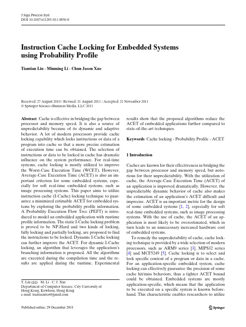
J Sign Process SystDOI 10.1007/s11265-011-0650-6Instruction Cache Locking for Embedded Systems using Probability ProfileTiantian Liu· Minming Li · Chun Jason XueReceived: 27 August 2010 / Revised: 31 August 2011 / Accepted: 21 November 2011© Springer Science+Business Media, LLC 2011Abstract Cache is effective in bridging the gap between processor and memory speed. It is also a source of unpredictability because of its dynamic and adaptive behavior. A lot of modern processors provide cache locking capability which locks instructions or data of a program into cache so that a more precise estimationof execution time can be obtained. The selection of instructions or data to be locked in cache has dramatic influence on the system performance. For real-time systems, cache locking is mostly utilized to improve the Worst-Case Execution Time (WCET). However, Average-Case Execution Time (ACET) is also an im-portant criterion for some embedded systems, espe-cially for soft real-time embedded systems, such as image processing systems. This paper aims to utilize instruction cache (I-Cache) locking technique to guar-antee a minimized estimable ACET for embedded sys-tems by exploring the probability profile information.A Probability Execution Flow Tree (PEFT) is intro-duced to model an embedded application with runtime profile information. The static I-Cache locking problem is proved to be NP-Hard and two kinds of locking, fully locking and partially locking, are proposed to find the instructions to be locked. Dynamic I-Cache locking can further improve the ACET. For dynamic I-Cache locking, an algorithm that leverages the application’s branching information is proposed. All the algorithms are executed during the compilation time and the re-sults are applied during the runtime. ExperimentalT. Liu (B) · M. Li · C. J. XueDepartment of Computer Science, City University ofHong Kong, Kowloon, Hong Konge-mail: tiantianster@ results show that the proposed algorithms reduce the ACET of embedded applications further compared to state-of-the-art techniques.Keywords Cache locking· Probability Profile · ACET1 IntroductionCaches are known for their effectiveness in bridging the gap between processor and memory speed, but noto-rious for their unpredictability. With the utilization of cache, the Average-Case Execution Time (ACET) ofan application is improved dramatically. However, the unpredictable dynamic behavior of cache also makesthe estimation of an application’s ACET difficult and imprecise. ACET is an important metric for the designof some embedded systems[1, 2 ], especially for soft real-time embedded systems, such as image processing systems. With the use of cache, the ACET of an ap-plication is most likely to be overestimated, which in turn leads to an unnecessary increased hardware costof embedded systems.To remedy the unpredictability of cache, cache lock-ing technique is provided by a wide selection of modern processors, such as ARM9 series[3 ], MIPS32 series [4] and MCF5249[5]. Cache locking is to select andlock specific content of a program or data in a cache.For an application-specific embedded system, cache locking can effectively guarantee the precision of some cache hit/miss behaviors, thus a tighter ACET bound could be obtained. Embedded systems are mostly application-specific, which means that the applicationto be executed on a specific system is known before-hand. This characteristic enables researchers to utilizeJ Sign Process Syst the application’s properties to make some informed 2 Related Workdecisions before the execution. Therefore, in this paper,we utilize instruction cache (I-Cache) locking technique Several previous work has been done regarding theto find an estimable minimized ACET for an embedded cache locking problem in embedded systems. The most system based on the probability profiling information related works to this paper are [6, 7]. Both of theof the specific application running on the system. two works target to eliminate conflict miss rate within In this paper, a Probability Execution Flow Tree a cache set to reduce the ACET. Anand et al. [6 ] (PEFT) is introduced to model an embedded applica- devise a cost-benefit model to discover the memory ad- tion’s program with its probability profile information dresses to be locked in the I-Cache. Their experiments and application-specific information. Two schemes of confirm that cache locking is beneficial in improving cache locking are considered: static and dynamic. In average case performance. However, their cost/benefitthe static locking scheme, cache contents are loaded formulation contains some profile information whichat application start-up and remain unchanged until is hard to be obtained or not accurate. Additionally,the end. In the dynamic locking scheme, locked cache they focus on finding the beneficial blocks which are contents can be changed at specific reloading points mapped to the same cache set. This will lead to anbased on the runtime information. The cache can be unbalance between different sets, because some setsfully locked or partially locked. The I-Cache locking may contain more valuable blocks while others may problem in this paper aims to analyze the application not. Liang et al. in [7 ] introduce temporal reuse profile during its compilation time, and select a set of nodes to model the cost and benefit of locking memory blocksto be locked in the I-Cache statically or sets of nodes to in the cache. They propose an optimal algorithm and abe reloaded and locked in the I-Cache dynamically. The heuristic approach that use the temporal reuse profilegoal is to optimize the ACET of an embedded system. to determine the most beneficial memory blocks. How- The contributions of this paper are as follows: ever, each cache set is also analyzed individually intheir work. When implementing their methods, both1. Propose I-Cache locking techniques to minimizeof the two works use the trampolines [8] approach to the average execution time of embedded applica-introduce the locking instruction to the binary code so tions by exploring applications’ statistical profilethat the mapping addresses of the blocks will not be information and application-specific foreknowingchanged.information.Most other researchers utilize I-Cache locking in2. Prove that the static I-Cache locking problem forreal-time applications to guarantee a tighter estimation ACET reduction is an NP-Hard problem, and pro-of Worst-Case Execution Time (WCET). Puaut et al.pose a fully locking algorithm and a partially lock-propose some heuristic methods about I-Cache locking ing algorithm.on minimization of WCET and Worst-Case Utilization 3. Propose an off-line algorithm for the dynamic I-(WCU) [9, 10 ].Campoy et al. use genetic algorithms Cache locking by exploring runtime branching in-for both static locking [11] and dynamic locking [12]i n formation. The outputs of the algorithm are usedmultitask, preemptive real-time systems. Falk et al. [13 ] during runtime.take the changing of worse-case execution path into The remainder of this paper is organized as fol- consideration and adopt a greedy strategy to choose lows. Section 2 presents related work. Section 3 an- instructions into cache. Liu et al. [14] study the static alyzes the cache architecture and presents the PEFT I-Cache locking problem to minimize WCET for real- model of an application. In Section 4, the static I- time embedded systems. The problem is proved to Cache locking problem is formulated using the in- be NP-Hard and optimal algorithms are proposed for teger linear programming model and proved to be subsets of the general problem with special propertiesNP-Hard. Fully locking and partially locking algo- and patterns.rithms are proposed respectively. For the dynamic Scratchpad memory is an alternative to cache. TheI-Cache locking problem, an off-line algorithm us- allocation of code/data to the scratchpad memory ising the static locking results and branching informa- under software control. Significant effort has beention to obtain the dynamic locking decisions is pro- invested in developing efficient allocation techniques posed in Section 5. Cache conflict problem caused for scratchpad memories. [15 , 16 ] aim at reducing theby cache locking is discussed in Section 6.S ection7 ACET of programs through memory access profiles. shows the experimental results compared with previ- Puaut et al. [17] propose an algorithm for off-line con- ous work. Finally, concluding remarks are presented in tents selection of on-chip memory, supporting both the Section 8.locked cache and scratchpad memory. They find thatJ Sign Process Systthe performance of applications using the two types of memory are very close to each other in most cases.Little previous work has explored the statistical in-formation and the foreknowing information of em-bedded applications for the I-Cache locking problem.Liang et al.[18 ] utilize the probability information ofan application for cache configuration design whichis orthogonal to this paper’s work. In[19], an ap-proach for early branch resolution and subsequent fold-ing is presented. The application-specific informationis captured by the micro-architecture through a low-cost reprogrammable hardware, thus attaining the twin benefits of processor standardization and application-specific customization. Several work has used the fore-knowing information to provide scheduling methodsto improve timing performance for embedded systems [20– 22 ].Although there were a number of previous efforts on the cache locking problem, most of them focus on re-ducing the WCET[9–14 ]. The most related work to this paper primarily targets to eliminate conflict miss ratewithin one cache set to improve the ACET[6][7 ]. The unbalanced and random distribution of the beneficialblocks in different sets may weaken their methods. Inthis paper, we consider the problem from a differentangle. We first target to find the most efficient blockswithin the whole block sets to minimize ACET, then we use compilation techniques, such as padding and codepositioning[26] to avoid conflicts among these selected blocks. As concluded in[17 ] that using locked cacheand scratchpad memory are very close to each other in most cases, the algorithms proposed in this paper canalso be applied to scratchpad memory allocation.3 Cache Architecture and Task ModelThis section introduces the notations used in this paper concerning the cache architecture and task model.3.1 Cache ArchitectureCache locking technique is supported by several com-mercial processors[3 ,4], with different implementation methods. Some processors, for example Intel XScale[23] and MPC603E[5 ], allow developers to lock theentire cache. While others, for example RC64574[24], allow developers to lock only part of the cache. Somep rocessors[4 ,23] insert specific cache locking opera-tions into the application’s code to perform locking,while others[5, 24] use specific lock/freeze bits intheir cache control registers to lock each single cacheline content. In this paper, we assume the processor is equipped with an I-Cache with a total size of S.The proposed work is applied to a general architecture based on the above processors, resulting in a cache architecture with the following characteristics:1)I-Cache locking can be applied to each line of theI-Cache, which implies that the I-Cache can betotally locked or partially locked. This capability isprovided by several commercial processors[5, 24]. 2)The I-Cache can be loaded using a cache-fillinginstruction, which is provided by lots of processors[4 ,23 ]. During system start-up, a small routine isexecuted to pre-load the cache using the cache-filling instruction. After pre-loading the blocks, thecache is locked. Under the static locking scheme,the locked cache content will never change. Whileunder the dynamic locking scheme, the cache con-tent could be changed at specific reloading pointsby invoking these cache-filling instructions.3)The I-Cache can be either direct-mapped or set-associative. The mapping from memory space tothe I-Cache, as well as the possibility of cacheconflict within the locking selection are solved byprevious compilation techniques, such as proce-dure re-ordering[25 ], padding and code position-ing[26 ], as discussed in Section6.4)If the processor addresses an instruction that islocked in the I-Cache, this instruction will beserved from the I-Cache, resulting in fast accesstime (hit). If the processor addresses an instructionthat is not locked in the I-Cache, this instructionwill be served from the main memory, resulting inlonger access time (miss).5)This paper focuses on I-Cache locking. Data cacheis assumed to work in a normal fashion.3.2 PEFTIn this paper, a Probability Execution Flow Tree (PEFT) is used to model an embedded application.PEFT embodies the control flow of the application’scode and the profiling information of the applicationso that we can analyze it to find which part of the code should be selected into the I-Cache.Definition 1 A PEFT= (V, E, B) is a weighted tree, where V represents the set of nodes and E representsthe set of edges. B is the set of basic blocks in a program. Each b∈ B is a context-specific code block associated with three attributes: block_miss(b) is the single processing time when basic block b is not in the cache, block_hit(b) is the single processing time when basic block b is in the cache and block_s(b) is theJ Sign Process Systsize of basic block b . Node v ∈ V represents the real execution of a code block b∈ B under a certain context and therefore has two attributes: name(v) = b where b∈ B representing that basic block b is executed in this node and count(v) representing the average number of times b is executed in the current context. Edge evu ∈ E denotes a program control flow from node v to node u. Each edge has one attribute: edge_ prob(evu) which represents the execution probability of this flow. Forevery node v,u|evu∈E edge_ prob (evu) = 1.To generate a PEFT, an algorithm PEFT_CON isused, as shown in Algorithm 1. An application is firstrun in a profile tool, and the probabilities of edges are obtained and recorded in a probability matrix P[v][u]. Then, algorithm EFT_CON in[14]isusedtocon-struct an Execution Flow Tree (EFT)[14 ] (line 1). Fi-nally, we attach the statistical probability to each edge(line 2–4).A PEFT example is shown in Fig.1. Figure1( a)isa segment of the benchmark “Audio beam former”[28]and Fig.1(b) is the corresponding PEFT.Some important features about PEFT are as follows:1)The framework of PEFT is similar to the frame-work of CFG (Control Flow Graph) used in pre-vious research[10 ]. In Algorithm EFT_CON[14],each code line is scanned and different controlflows are processed accordingly. The sequentialcodes are the simplest and are treated as one ba-sic block. For branches, loops and routine calls,we process their bodies recursively and attach theEFTsub obtained to the main EFT. The differencebetween PEFT and CFG is that PEFT is explic-itly defined as a tree with probability informationand other attributes related to cache behavior. Abasic block can be one or more statements in theprogram depending on the context. For example,statement “exit(1)” in this example forms node 3in Fig.1(b).For simplicity, some of the call proce-if (!data_file) {print_usage();exit(1);}if (search_far_field == 1) {max_energy = search_far_field_angles(max_result, data_file, output_file, hamming);} else if (hill_climb == 1) {search_grid(source_location, data_file, output_file, hamming);max_result = (float*) malloc(ANGLE_ENERGY_WINDOW_SIZE*sizeof(float));} else {calc_single_pos(source_location, mic_locations, hamming, data_file, output_file);}exit(0);exit( )3print_usage( )21if (!data_file)6max_result = return of node 57search_far_field_angles( )8max_energy = return of node 75malloc( )exit( ) 12if (search_far_field == 1)49 if (hill_climb == 1)11 calc_single_pos( )14 exit( )10search_grid( )13exit( )95%5%31%69%73%27%(a) A segment of a benchmark [25].(b) Its PEFT.Figure 1 A segment of a benchmark and its PEFT.dures of the PEFT in Fig.1(b) are not presentedrecursively. For example, node 7 is an abstract pre-sentation of routine “search_far_field_angles()” .Algorithm EFT_CON does recursively process thesubroutines.2)In practical systems, the value of block_miss(b)orblock_hit(b) of a basic block b is not an accu-rate value if we consider timing anomalies, cacheand pipeline effects. It can be a range of values.In this paper, we use the average-case value ofblock_miss(b) orblock_hit(b) to form a modelfor solving the locking problem and comparingwith previous works. We run the benchmark sev-eral times using SimpleScalar[29 ] and obtain theprofiling information. From the cache miss/hit in-formation, we can obtain the estimation value ofblock_miss(b) orblock_hit(b).3)Node v has three additional attributesnode_miss(v), node_hit(v) and node_prob(v).node_miss(v) ornode_hit(v) is the real executiontime of node v and can be calculated asnode_miss(v) = block_miss(name(v)) × count (v)or node_hit(v)= block_hit(name(v)) × count(v),depending on whether name(v) is put inthe cache.node_ prob(v) is the executionJ Sign Process Systprobability of node v and can be calculatedas node_ prob(v)=node_prob(u)×edge_prob(euv),where u is the parent of v. It is easy todeduce that node_ prob(v) = node_prob(v0) ×edge_ prob(ev0 u1 )× edge_prob(eu 1 u2 )× ··· ×edge_ prob(euv) for node v along the path fromroot v0 to node v,wherenode_prob(v0) = 1.4)Algorithm EFT_CON gives the main flow of aloop. For a node v in a loop, the execution timeof its basic block could be different between itsfirst execution and each successive repetitionbecause of cache reusing[30]. The value ofnode_miss(v) can be calculated as node_miss(v) =block_miss(name(v)) + block_hit (name(v)) ×(count(v) − 1) which is its execution time underthe uncontrolled cache. The node_hit(v) is stillnode_hit(v) = block_hit(name(v)) × count(v).5)There is a procedure Duplicate() in AlgorithmEFT_CON. If a node v has an indegree(v) of atleast 2, Duplicate() instantiates the structure start-ing from v by indegree(v) times, which ensures thatthe output is a tree. For example, nodes 12, 13and 14 in Fig.1 (b) are duplicating nodes whichare introduced by the procedure Duplicate(). Eachduplicating substructure represents an invocationof the associated basic blocks (in this example,it is code line “exit(0)”), so they have the samename and count value, thus same node_miss(v) andnode_hit(v). With these duplicated nodes, thePEFT structure is still equivalent to EFG[13]or CFG[10] structure. From the definition andEFT_CON algorithm, we know that every path inan EFG or CFG is enumerated in a PEFT, whileevery path in a PEFT corresponds to one possiblepath in an EFG or CFG.3.3 ACET of a PEFTACET is the expected length of the root-leaf pathin a PEFT. Let Pi= (pi0 pi1 ... pil i )be a root-leaf path, where pi0, pi1,..., pili ∈ V and li is thenumber of edges on path Pi.Eachpath Pi has twoattributes length(Pi) and probability(Pi). length(Pi)is defined as the summation of the weights ofnodes on Pi, which represents the execution timeof this path.Let Wreal(v) = (1 − δ(name(v))) ×node_mi s s(v) + δ(name(v)) × node_hit(v),whereδ(name(v)) = 1 if name(v) is put in the cacheandδ(name(v)) = 0 otherwise. The length(Pi) is calculated as length(Pi) =li j=0 Wreal( pij). The other attributeprobability(Pi) represents the execution probability of this path and is calculated as probability(Pi) =li−1j=0 edge_ prob (epij pij+1 ).Table 1 Notations used in this paper.Notation Descriptionb A basic blockblock_s(b)Size of basic block bblock_miss(b)Execution time of basic block b when bis not in cacheblock_hit(b)Execution time of basic block b when bis in cacheblock_ prob(b)Execution weight of basic block beach_sa ving(b)ACET saving of basic block bv A nodename(v)Basic block in node vcount(v)Execution count of basic block in node v node_ prob(v)Execution probability of node vnode_miss(v)Execution time of node v when name(v)is not in cachenode_hit(v)Execution time of node v when name(v)is in cacheWreal(v)Real execution time of node v,is equal to node_miss(v) ornode_hit(v) evu An edgeedge_ prob(evu)Execution probability of edge evuPi A root-leaf pathlength(Pi)Execution time of path Piprobability(Pi)Execution probability of path PiDenote the total number of the root-leaf paths as|P|, then the ACET of a PEFT can be calculated as:|P|i=1length(Pi) × probability(Pi)(1) The notations are summarized in Table1.4 Static I-Cache LockingAs discussed in Section3.1, first we want to find a most efficient locking selection of memory blocks to mini-mize ACET of the application. In this section, we dis-cuss the static locking scheme, where cache contents are loaded at application start-up and remain unchangeduntil the end. We further consider two different locking strategies: fully locking and partially locking, depend-ing on whether or not the whole I-Cache is locked.4.1 Fully LockingThe fully locking means that the whole I-Cache is usedas the locked cache.J Sign Process Syst 4.1.1 Problem FormulationThe ACET minimization problem using static I-Cachelocking can be defined as follows. Given an I-Cache ofsize S and a PEFT representing a given program, theaim is to put a subset of basic blocks into the I-Cacheso that the total size of the chosen basic blocks doesnot exceed S and the ACET of the PEFT is minimized.With Formula1 discussed in Section3.3,w eformulatethe fully static I-Cache locking problem as an integerlinear programming (ILP) instance as follows:min|P|i=1length(Pi) × probability(Pi)s.t.⎧⎪⎪⎪⎪⎪⎪⎨⎪⎪⎪⎪⎪⎪⎩length(Pi) =li j=0(1 − δ(name(v))) × node_miss(v)+δ(name(v)) × node_hit(v)probability(Pi) =li−1j=0 edge_ prob (epij pij+1 )b∈Bblock_s(b) × δ(b) ≤ Sδ(b) ∈{0, 1}The variables in this ILP formulation areδ(b) foreach basic block which can only be equal to 0 or 1.The first two groups of equations give the calculationof length(Pi) and probability(Pi). The third inequalityis I-Cache size limitation. Because we use the lock-ing technique with the entire cache, every time weshould maintain this limitation no matter which kindof mapping is used. Otherwise, we will not be ableto put all the selected nodes to the cache. It is truethat some instructions may be mapped to the samecache line. This cache conflicts may happen with both direct-mapped cache and set-associative cache. We can apply some compiling techniques[26] to solve the cache conflict problem after we have decided which nodes to lock, which will be studied in Section6. The goal ofthe problem is to minimize the ACET for the PEFT by determiningδ(b) for each b ∈ B.4.1.2 Problem AnalysisFor each node v in a PEFT, define its set of outgo-ing edges as OutEdgesv ={evtm |e vtm ∈ E, 1 ≤ m ≤ Mv}, whereMv is the out-degree of node v.Let u representthe preceding node of v and ti represent the successive node of v for a path Pi which has v on it. The terms relating to Wreal(v) (node_miss(v) or node_hit(v))in Formula1 can be combined and further transformedas follows:Pi vWreal(v) × probability(Pi)= Wreal(v)×Pi v(edge_prob(epi0 pi1 )×···× edge_prob(euv)prob(evti )×··· × edge_prob(epili−1pili ))= Wreal(v) × (edge_prob(epi0 pi1 )×···×edge_ prob (eu v)×Pi v&ti=tm1≤m≤Mv(edge_prob(evtm )×···×edge_prob(epili−1pili )))= Wreal(v) × (edge_prob(epi0 pi1 )×··· × edge_prob(euv))= Wreal(v) × node_prob(v)As can be seen from the above, for every node v, the corresponding portion in Formula1 is Wreal(v) ×node_ prob(v).Formula1 can be expressed with regardto node v as:v∈VWreal(v) × node_prob(v)(2)In a PEFT, one basic block can be called by different nodes. In other words, name(u) could be equal toname(v) even when u = v. This scenario is denoted asreusing in this paper. Considering reusing, Formula2can be further transformed into:v∈VWreal(v) × node_prob(v)=v∈V((1 − δ(name(v))) × block_miss(name(v))+ δ(name(v))block_hit(name(v)))× count(v) × node_prob(v)=b∈B(((1 − δ(b)) × block_miss(b) + δ(b)× block_hit(b))v∈V& name(v)=b(count(v)× node_prob(v)))Let block_ prob(b) =v∈V& name(v)=b (count(v) ×node_ prob(v)). It is a constant when a PEFT is given.It represents the execution weight of basic block bappearing on different nodes in a PEFT. It may scaleJ Sign Process Systbigger than 1, so we do not say it is a probability.Finally, Formula1 is reduced to:b∈B((1 − δ(b)) × block_miss(b) + δ(b)× block_hit(b)) × block_prob(b)(3)Define each_sa ving(b) = (block_miss(b) − block_hit(b)) × block_prob(b) which is the ACET saving foran individual b∈ B. The static I-Cache locking prob-lem can be proved to be an NP-Hard problem.Theorem 1 The static I-Cache locking for ACET mini-mization is NP-Hard.Proof We prove that this problem is NP-Hard by areduction from the 0/1 knapsack problem. Given a0/1 knapsack instance, we have the finite set A withweight weight(a) and value value(a) for each a ∈ A,a value threshold K and a total weight limit W.Thestatic I-Cache locking problem is constructed as fol-lows. For each a∈ A,wecreateabasic block ba ∈B with each_sa ving(ba) = value(a) and block_s(ba) = weight(a). This instance can be constructed in polyno-mial time from the 0/1 knapsack instance.Define Total_time_unlock= b a∈B block_miss(b a)×block_ prob(ba).Formula3 can be transformed asTotal_time_unlock− b a∈B δ(b a) × each_saving(b a), whereδ(ba) = 1/0 means whether ba is put intocache or not. The deterministic version of staticI-Cache locking problem is to find whether there is aδ(ba) = 0/1 for every ba ∈ B whichcan achieve:Total_time_unlock− b a∈B δ(b a) ×each_sa ving(ba) ≤ Total_time_unlock − K and b a∈F block_s(b a) × δ(b a) ≤ S.This can be done if and only if there is aδ(a) = 0/1 for every a∈ A such that a∈A δ(a) × value(a) ≥ K and a∈A weight(a) × δ(a) ≤ W. Thus the desired δ(a)for every a∈ A exists for the instance of 0/1 knapsackif and only if aδ(ba) for every ba ∈ B exists for the cor-responding instance of static I-Cache locking problem.4.1.3 AlgorithmWhen we consider to lock all the I-Cache of size S,a dynamic programming method can be used to solvethe 0/1 knapsack problem optimally within pseudo-polynomial time[31]. In the static I-Cache locking problem, the transformed objective shown in Formula3 is not related to the PEFT’s structure. Therefore,we can treat basic blocks as items in the 0/1 knapsack problem and carry out dynamic programming similarly. The Algorithm SICL (Static I-Cache Locking for a PEFT) is shown in Algorithm 2.In Algorithm SICL,CalcFunProb(PEFT)isa procedure to calculate block_ prob(bi) and each_sa ving(bi) for each bi ∈ B (line1). Thechoice made under each circumstance is kept using anarray structure OPT[|B|][S + 1] (line 2). Each OPT[i][s] keeps the optimal solution for basicblock subset{b1, ··· bi} under cache size s withtwo variables: Sa ving and Cachable (lines 7–8, 11–12), which respectively represent the maximizedACET saving for this subset and whether or。
嵌入式系统设计报告英文含代码

1.System Design SchemaThis system is called speech spectrum analyzer based on the development tools called TM320C6416. The software is tested on code composer studio 6416(CCS6416). The system can realize the function that It can analyse the spectrum of the speech signals inputted by fast fourier transform(FFT) algorithm, and then print the frequency by ergodic algorithm, which can help find the number of the maxmum magnitude location . In addition, the system also can paly the voice which was recoded before. The C6X is used to designate a member of Texas Instruments’ (TI) TMS320C6000 family of digital signal processors. The architecture of the C6x digital signal processor is very well suited for numerically intensive calculations. The FFT with the radix-2 algorithm is a efficient algorithm that is used for converting a time-domain signal into an equivalent frequency-domine signal , based on the discrete frouier transform(DFT), The FFT reduces considerably the computational requirements of the DFT. The DFT of a discrete-time signal x (nT ) isNj N n nk e W N k W n x k X /2101......2,1,0 )()(π--==-==∑The FFT algorithm takes advantage of the periodicity and symmetry of the twiddle constants to reduce the computational requirements of the FFT. From the periodicity of W ,kk WN+W=and from the symmetry of Wk W+2/NkW-=An eight-point FFT is illustrated through the following exercise. We will see that flow graphs for higher-order FFT (larger N) can readily be obtained.figure1. Eight-point FFT flow graph using DITFor the reason that the speech signals recognition is quite hard ,so 512-point FFT has been adopted. After FFT algorithm finished, 512 magnitudes will be acquired. Then the maximum value will be found by the ergodic algorithm, and we can get the accurate frequency by the equation of number/max*_=, andf_samplefsnumberthen print it in CCS. Besides, I have set many flags to identify whether the frequency belongs to high frequency, or low frequency by the way of the LED turning on.2.Goal and Test Level of the system AchievedThe system can record the voice in surroundings, and then play what it records,besides, the system can also analyse the frequency of the recording voice by FFT algorithm. And t the analysed speech signal spectrum by C language can be a consistent with what is analysed by the built-in algorithm of CCS6416. I have compared the result produced by C language and the result of the CCS6416’s built-in GUI FFT algorithm, and I can get the perfect accordance with just 0.002% deviation. So the system can reach to the purpose accurately.3.Block Diagram and Flow Chart of System ImplementationThis system consists of three parts, one is speech signal acquisition module, and another is signal processing module, which is finished by STM320C6416 and FFT algorithm, and the last is speech sognal output module.Block Diagram is showed in figure2:figure2 block biagram of speech signal spectrum analysis systemFlow chat of system is shown in figure3:f igure3 flow chart of speech signal spectrum analysis systemAfter burnprocess has been finished, the system is waiting. In the case of testing the switch has been pressed, the record function starts, and the record will finish in the condition that switch three has been uplifted or the buffer is been fulfilled with that can be observed if the LED three is off. And then if switch zero has been pressed, the system will begin to play what has record before, and playing is finished in the condition of switch zero is uplifted, the the FFT begin after LED one turning on. The frequency will be printed in the CCS6416, and while LED one turns off ,it means the FFT is over, and the whole function has been finished.4.the Key Point and Difficulties of System ImplementationThe key point of this system is the implement of FFT algorithm. FFT algorithm has to analyze the spectrum of speech signal accurately, which is hard for C language to implement. The difficulties of the system implementation lies on the FFT algorithm’s operatoring speed and accuracy. I adopted 512-point FFT analysis, and then I find the maximum magnitude by ergodic algorithm, which has to compare all 512 points with each other to find the maxmum magnitude. There is no doubt that it istime-consuming. So the system can not fulfilled the real-time capability of computing magnitude.5.Core Code and Explanation of SystemThe code of the system is listed as follows://record.c record/play input using external memory#include <stdio.h>#include "math.h"#include "dsk6416_aic23.h" //codec supportUint32 fs=DSK6416_AIC23_FREQ_8KHZ; //set sampling rateUint16 inputsource=DSK6416_AIC23_INPUT_MIC; // select inputunsigned long i,count,s;short buffer[N];short buffer1[SAMPLENUMBER];long m;float max;void InitForFFT();int INPUT[SAMPLENUMBER],DATA[SAMPLENUMBER];float fWaveR[SAMPLENUMBER],fWaveI[SAMPLENUMBER],w[SAMPLENUMBER]; float sin_tab[SAMPLENUMBER],cos_tab[SAMPLENUMBER];#pragma DATA_SECTION(buffer,".EXT_RAM") //buffer ->external memoryvoid main(){int q,t,n,m,l,tt=0;short playing = 0;•DSK6416_DIP_init();DSK6416_LED_init();comm_poll(); //init DSK, codec, McBSPInitForFFT();count=0;while(1) //infinite loop{if(DSK6416_DIP_get(3) == 0) //if SW#3 is pressed{DSK6416_LED_on(3); //turn on LED#3buffer[count++] = input_left_sample();}if(DSK6416_DIP_get(3) ==1||(count>=N-1)) //if SW#3 is pressed {DSK6416_LED_off(3);}}if(DSK6416_DIP_get(0)==0) //if SW#0 pressed{count=0;playing = 1;while (playing == 1){DSK6416_LED_on(0); //turn on LED#0output_left_sample(buffer[count++]);if(count>=N-1){DSK6416_LED_off(0);•for(s=50;s<N/SAMPLENUMBER;s++){n=0;for(l=SAMPLENUMBER*(s-1);l<s*512;l++){n=l-SAMPLENUMBER*(s-1);buffer1[n]=buffer[l];for(q=0;q<SAMPLENUMBER;q++) {fWaveR[q]=buffer1[q];fWaveI[q]=0.0f;}FFT(fWaveR,fWaveI);max=w[0];m=0;for(t=0;t<SAMPLENUMBER/2;t++){if(max<w[t]){max=w[t];m=t;}}}//for(l=SAMPLENUMBER*(s-1);l<s*512;l++) tt=m*8000/SAMPLENUMBER;if(tt>=1046&&tt<=1975){DSK6416_LED_on(1);DSK6416_LED_on(2);}else if(tt>513) DSK6416_LED_on(2);else if(tt>0) DSK6416_LED_on(1);else{DSK6416_LED_on(3);DSK6416_LED_on(1);DSK6416_LED_on(2);}if(tt>25)printf("%d\n",tt);DSK6416_LED_off(1);DSK6416_LED_off(2);DSK6416_LED_off(3);}//for(s=1;s<N/SAMPLENUMBER;s++)count=0;} //if(count>=N-1)} // while (playing == 1)playing=0;DSK6416_LED_on(0);} //if(DSK6416_DIP_get(0)==0)}//while(1)}//mainvoid FFT(float dataR[SAMPLENUMBER],float dataI[SAMPLENUMBER]) {int x0,x1,x2,x3,x4,x5,x6,x7,x8,xx;int i,j,k,b,p,L;float TR,TI,temp;/********** following code invert sequence ************/for ( i=0;i<SAMPLENUMBER;i++ ){x0=x1=x2=x3=x4=x5=x6=x7=x8=0;x0=i&0x01; x1=(i/2)&0x01; x2=(i/4)&0x01; x3=(i/8)&0x01;x4=(i/16)&0x01; x5=(i/32)&0x01; x6=(i/64)&0x01;x7=(i/128)&0x01;x8=(i/256)&0x01;//x=x0*1024+x1*512+x2*256+x3*128+x4*64+x5*32+x6*16+x7*8+x8*4+x9*2+x10;xx=x0*256+x1*128+x2*64+x3*32+x4*16+x5*8+x6*4+x7*2+x8;dataI[xx]=dataR[i];}for ( i=0;i<SAMPLENUMBER;i++ ){dataR[i]=dataI[i]; dataI[i]=0;}/************** following code FFT *******************/for ( L=1;L<=9;L++ ){ /* for(1) */b=1; i=L-1;while ( i>0 ){b=b*2; i--;} /* b= 2^(L-1) */for ( j=0;j<=b-1;j++ ) /* for (2) */{p=1; i=9-L;while ( i>0 ) /* p=pow(2,7-L)*j; */{p=p*2; i--;}p=p*j;for ( k=j;k<SAMPLENUMBER;k=k+2*b ) /* for (3) */{TR=dataR[k]; TI=dataI[k]; temp=dataR[k+b];dataR[k]=dataR[k]+dataR[k+b]*cos_tab[p]+dataI[k+b]*sin_tab[p];dataI[k]=dataI[k]-dataR[k+b]*sin_tab[p]+dataI[k+b]*cos_tab[p];dataR[k+b]=TR-dataR[k+b]*cos_tab[p]-dataI[k+b]*sin_tab[p];dataI[k+b]=TI+temp*sin_tab[p]-dataI[k+b]*cos_tab[p];} /* END for (3) */} /* END for (2) */} /* END for (1) */for ( i=0;i<SAMPLENUMBER;i++ ){w[i]=sqrt(dataR[i]*dataR[i]+dataI[i]*dataI[i]);}} /* END FFT */Firstly, I set the sampling fruquency as 8 Khz, and the total buffer number is 512000which means that it can record the voice as long as 64 seconds. The core of the code includes three parts. One is the recording part, and the second is playing part, and the third is the FFT analysis part. While the DSP chip detect the switch three was pressed, then recording starts. Recording is accomplished by the fuction called input_sample., which can complete the AD sampling and store the sampled value into buffer. LED three will turn off while the buffer has been filled or the switch three is uplifted. Then if you press switch zero, then playing starts, which can paly what has been recorded. And the playing part is accomplished by the function called output_sample, which can read the discrete value in the buffer and turn in to analogy speech signal. After the palying is over, LED zero will turn off, and LED one will turn on indicating that FFT with the radix-2analysis begins. FFT algorithm computing is accomplished by looking up to table, and the table is made up by the sine function and cosine fuction, we will get the real and imaginary parts of magnitudes. And then by the way of ergodic algorithm to find the accurate number of location of the maxmum magnitude. We will get the frequency by equation of numbermax*/_,numbersamplefsf_After the FFT finished, LED one will turn off, and the speech signal spectrum analyzer has fulfilled all function.6.Debugging Recording of System and Testing IllustrationEach time, FFT analyze 512 points. So I divide the whole buffer into lots of little buffer containing 512 points. The debugging processing mainly depends on the location of breakpoints. I set the breakpoint in the location of FFT analyze of each little buffer called buffer1, and when the code execute the location of breakpoint, I open the view of FFT analyze of CCS6416 built-in, and compared the result printed by the FFT algorithm realized by C language and the result of the view of FFT to decide while they are the same with each other, or just with a little deviation. When the breakpoint was set in the location of first 512-point buffer, the result is in the below:And the second 512-point buffer compareing results is shown in the figure5:figure5 the compareing result of the second 512-point buffer7.Result of SystemThe testing can proved that the result of the system can reach to the ideal propose, which not only can play the voice of what has been recorded, but also can accuratelyobtain the frequency of the voice, just with devation of less then 0.002%.评分注: 1 无评卷人签名试卷无效。
关于计算机嵌入式系统的检索报告

关于计算机嵌入式系统的检索报告
摘要
本文研究的主题是计算机嵌入式系统。
本文介绍了嵌入式系统的基本
概念、分类、特点、发展历史以及应用领域。
提出了几种嵌入式系统实施
的常见方法,例如:处理器核心、外设和操作系统的设计和实现等。
最后,介绍了嵌入式系统的发展趋势。
本文旨在通过对嵌入式系统的详细介绍,
加深读者对嵌入式系统的了解。
关键词:计算机嵌入式;分类;特点;发展历史;实施
1. Introduction
2. Basic Concepts of Embedded System
嵌入式系统是一个特殊的硬件系统,是将软件和硬件结合组成的系统。
它是由一个处理器核心和周边外设共同组成的硬件系统,处理器核心同时
包含控制单元和运算单元。
它通过一个嵌入式操作系统控制其内部的处理
器核心和外设,实现硬件和软件的完美结合。
3. Classification of Embedded System
根据不同的处理器核心和嵌入式操作系统。
嵌入式专业英语

P PROM(可编程只读存储器) Programmable Read-Only Memory. A type of ROM that can be written (programmed) with a device programmer. These memory devices can be programmed only once, so they are sometimes referred to as write-once or one-time programmable devices. 可编程只读存储器。能被设备编程器写的一种ROM。这种内存设备可以被编程一次,所以它们有时被作为写一次或一次性编程设备来看待。
Multitasking (多任务)The execution of multiple software routines in pseudo-parallel. Each routine represents a separate "thread of execution" and is referred to as a task. The operating system is responsible for simulating parallelism by parceling out the processor"s time. 伪并行运行的多个软件程序。每一个程序表现得像分开的“执行的线程”并且被看作是一个任务。操作系统通过分配处理器时间来模拟并行方式。
N NVRAM Non-Volatile Random-Access Memory. A type of RAM that retains its data even when the system is powered down. NVRAM frequently consists of an SRAM and a long-life battery. 非易失的随机访问存储器。一种能在系统关机的情况下保持它的数据的RAM。NVRAM常常由SRAM和长寿命电) A hardware debugging tool that allows you to view the voltage on one or more electrical lines. For example, you might use an oscilloscope to determine if a particular interrupt is currently asserted. 一种硬件调试工具,它让你能观察到一个或更多电路上的电压。例如:如果一个特殊的中断发生,你可以用一个示波器去检测它。
嵌入式社会实践报告开头

嵌入式社会实践报告开头英文回答:Embedded social practice is an essential part of my education and career as an engineer. It involves applying my knowledge and skills in real-world situations, specifically in the field of embedded systems. This practice allows me to gain hands-on experience and understand the practical implications of the concepts I have learned in my academic studies.One example of my embedded social practice experience was during an internship at a technology company. I was assigned to work on a project that involved designing and implementing an embedded system for a home automation system. This system allowed users to control various appliances and devices in their homes through a smartphone application.During this project, I had to collaborate with a teamof engineers from different disciplines, including hardware, software, and user interface design. We had regularmeetings to discuss the progress of the project, share ideas, and address any challenges or issues that arose. I also had the opportunity to interact with clients andgather their requirements and feedback.Through this experience, I learned the importance of effective communication and teamwork in achieving project goals. I also gained a deeper understanding of the challenges and considerations involved in developing embedded systems for real-world applications. Additionally, I developed problem-solving skills and the ability to adapt and make decisions in a dynamic and fast-paced environment.中文回答:嵌入式社会实践对于我作为一名工程师的教育和职业生涯来说是至关重要的一部分。
嵌入式英语词汇查询手册

嵌入式英语词汇查询手册ASIC(专用集成电路)Application-Specific Integrated Circuit. A piece of custom-designed hardware in a chip.专用集成电路。
一个在一个芯片上定制设计的硬件。
address bus (地址总线)A set of electrical lines connected to the processor and all of the peripherals withwhich itcommunicates. The address bus is used by the processor to select aspecific memory location or register within a particular peripheral. If the address bus contains n electrical lines, the processor can uniquely address up to 2^n such locations.一个连接处理器与所有外设的,用来通讯的电子线路集。
地址总线被处理器用来选择在特定外设中的存储器地址或寄存器。
如果地址总线有n条电子线路,处理器能唯一寻址高达2^n的地址空间。
BSP(板卡支持包)See board support package.board support package(板卡支持包)Part of a software package that is processor or platform-dependent. Typically,sample source code for the board support package is provided by the package developer. The sample code must be modified as necessary, compiled, and linked with the remainder of the software package.软件包的具有平台依赖性的那一部分。
外文文献翻译嵌入式
毕业设计翻译文献文献题目:Construction of Embedded System Platform which Based on μC/OS-Ⅱ and ARM7 Kernel Microprocessor 构建基于μC/ OS-Ⅱ和ARM7内核微处理器的嵌入式系统平台学生姓名:易康乐学院:信息与通信工程学院专业:电子信息工程指导教师:万忠民2015年 5 月 10 日构建基于μC/ OS-Ⅱ和ARM7内核微处理器的嵌入式系统平台Yujun Bao Xiaoyan Jiang摘 要今天,嵌入式系统被广泛地应用于各行各业。
引入嵌入式操作系统在嵌入式发展中已经是一种趋势。
嵌入式操作系统能够适用于不同的系统硬件,并能够显著的减少开发费用,缩短研究周期。
μC/ OS-Ⅱ是一款优秀的开源,轻型内核,占用少量资源并且在实时性方面有着高性能的嵌入式操作系统。
μC/ OS-Ⅱ适用于越来越多的32位ARM7核微处理器,本文介绍了基于ARM7微处理器的μC/ OS-Ⅱ嵌入式操作系统的移植方法。
最终实现了构建基于μC/ OS-Ⅱ和ARM7内核处理器的嵌入式开发平台。
该平台能有效的简化软件程序开发流程,并缩短工程研究的周期和显著提高系统的执行效率。
关键字:嵌入式系统;嵌入式操作系统;ARM7内核;μC/ OS-Ⅱ一、介绍所谓的操作系统移植是一个实时操作系统内核可以在运行在其他微处理器上。
移植部分对于不同的CPU具有对应的不同的代码。
大多数μC / OS-Ⅱ代码是用C编程语言编写的,这对于移植μC / OS -Ⅱ是非常方便的。
但根据不同的微处理器,用户仍然需要使用汇编语言编写一些有关不同微处理器的硬件的程序。
这是因为当μC / OS-Ⅱ读或写寄存器时,它只依赖于汇编语言。
因为μC / OS -Ⅱ操作系统的要求,有三个文件需要当μC / OS-Ⅱ移植到一个特定的微处理器。
整个移植工作主要围绕创建这三个文件。
这些文件显示如下:1、在C语言中的头文件OS_CPU中,一些与编译器无关的数据类型需要定义OS_CPU中。
嵌入式系统概论-英文
2
1.1 Introduction
Embedded system is widely used, it becomes the one of the fastest developing fields. The study of embedded system has a very important practical significance This chapter introduces the definition of embedded system and system structure analysis of embedded system, status, prospects the development trend of the field.
10
1.3 The characteristics of embedded system
5. Embedded operating system support With a general purpose computer operating system, embedded operating system has the advantages of small volume, reliable, real-time and can be cut, can be cured and multiple processor support characteristics, and the operating system is generally a real-time operating system. Embedded real-time operating system is introduced, and improving the reliability of the system and application development efficiency.
嵌入式实验报告llisa

一、相关知识根据IEEE(国际电机工程师协会)的定义,嵌入式系统是“Devices Used to Control,Monitor or Assist the Operation of Equipment,Machinery or Plants。
”即控制、监视或者辅助装置、机器和设备运行的装置。
目前国内一个普遍被认同的定义是:以应用为中心、以计算机技术为基础、软件硬件可裁剪、适应应用系统对功能、可靠性、成本、体积、功耗严格要求的专用计算机系统。
可以这样认为,嵌入式系统是一种专用的计算机系统,作为装置或设备的一部分。
通常,嵌入式系统是一个控制程序存储在ROM中的嵌入式处理器控制板。
事实上,所有带有数字接口的设备,如手表、微波炉、录像机、汽车等,都使用嵌入式系统,有些嵌入式系统还包含操作系统,但大多数嵌入式系统都是是由单个程序实现整个控制逻辑。
嵌入式系统是计算机软件和硬件的综合体,可涵盖机械或其他的附属装置。
所以嵌入式系统可以笼统地分为硬件和软件两部分。
嵌入式系统的构架可以分成四个部分:处理器、存储器、输入输出(I/O)和软件(由于多数嵌入式设备的应用软件和操作系统都是紧密结合的,在这里我们对其不加区分,这也是嵌入式系统和通用PC系统的最大区别)。
嵌入式系统的组成如下图所示。
本学期的实验采用英特尔公司于2003年底推出的PXA270嵌入式处理器。
PXA270更适合传统PDA,手持PC,平板电脑,智能手机市场。
它最初出现在PDA(比如惠普HP4700)和智能手机(如MOTO E680)上。
因此它的扩展接口相当丰富,扩展接口有SD/SDIO/MMC、CF/PCMCIA、CMOS/CCD CAMERA、蓝牙、USB1.1、OTG等。
许多厂商选择PXA270作为PMP处理器,是源于它wireless MMX技术和SpeedStep动态电源管理技术。
SpeedStep技术原用于英特尔移动处理器,这种技术用通俗的语言表述就是系统需要多高的主频,它就调节到多高的频率,系统不需要时,它就将处理器主频调节到最低,绝不浪费一点点。
嵌入式技术应用网络调研报告总结范文

嵌入式技术应用网络调研报告总结范文Embedded technology is the integration of hardware and software to perform a specific function within a larger system. It has found applications in various fields such as automotive, consumer electronics, healthcare, and industrial automation. 嵌入式技术是硬件和软件的结合,用于在较大系统中执行特定功能。
它已经在汽车、消费电子、医疗保健和工业自动化等领域找到了应用。
One of the key advantages of embedded technology is its ability to provide real-time processing and control of devices. This is essential in applications where timing is crucial, such as in automotive safety systems or industrial control systems. 嵌入式技术的一个关键优势是它能够提供设备的实时处理和控制。
这在时间至关重要的应用中至关重要,比如在汽车安全系统或工业控制系统中。
Moreover, embedded technology enables devices to operate efficiently with low power consumption, making it ideal for portable and battery-powered applications. This energy efficiency is crucial in modern electronics to prolong battery life and reduce environmental impact. 此外,嵌入式技术使设备能够以低功耗高效运行,使其成为便携式和电池供电应用的理想选择。
嵌入式系统(英文版)

Embedded systems with limited power resourcesThis paper deals with the design approach for embedded systems with limited power re-sources. The focus is on embedded systems powered purely by energy harvested from the surroundings. Realtime operation and power consumption are critical design aspects of these systems. A number of design problems are discussed and solutions are presented. Selected products are looked at as examples of successful implementation of the solutions.Attila Strba, Research & Development, EnOcean GmbH1. INTRODUCTIONSignificant advances in microelectronics technology made the increasing miniaturization of embedded systems possible. This trend to miniaturization began in the late 1960s and, as stated by Moore’s Law [3] that the power of microprocessors doubles about every 18 months, has held true with astonishing accuracy and consistency until the beginning of the 21st century. An announcement like that by IBM concerning the use of 29.9 nm technology to print circuits [7] indicates that this trend will continue for a number of chip generations.The trend is leading to and will result in the development of tiny embedded systems, integrated into more and more everyday objects. And will create a world of smart devices surrounding us. For exam-ple, parents will no longer lose track of their children, even in the busiest crowds, when location sen-sors and communication modules are sewn into their clothes. Similar devices attached to timetables and signposts could guide blind or foreign people in unknown environments by talking to them [6]. Another interesting possibility offered by such technology would be the creation of intelligent homes where a refrigerator can detect old food, a washing machine can query the instructions for dirty clothes, or window and door handles indicate whether they are open or closed. This concept called ambient intelligence, where humans have computing and networking technology embedded in their surroundings, was developed by the ISTAG advisory group [4], [5], [6].While this vision may sound utopian when you first hear about it, current technology is already at a stage where it is possible to realize it. Ambient intelligence requires that there be thousands of tiny embedded devices in the environment. Each of these devices require some source of power for it to function. While power can be sent to them through cables or batteries, neither of these possibilities offers an effective and longterm solution. The large number of these devices makes it highly desirable that they be fully self-sustaining and service-free. This can be achieved by harvesting energy from the environment.Energy harvesting is a way of using the omnipresent sources of energy in our surroundings, like from moving objects, vibrating machine parts, temperature changes, electromagnetic waves such as light, radio or infrared [8], [9]. The idea is not new, but successful and low-cost realization in embedded systems calls for the right expertise. A specific design approach is needed for embedded systems fulfilling the concept of ambient intelligence.EMBEDDED SYSTEMS WITH LIMITED POWER RESOURCES2. EMBEDDED SYSTEM DESIGN WITH LIMITED POWER RESOURCESEach system design has to begin with a specification. Focusing on devices for an ambient intelligence application, we will look at the design problems of embedded systems expected to satisfy the following requirements:self-sustaining and service-freeenergy harvesting from the environmentseamless wireless communication interfaceinteraction with realtime eventsunobtrusive hardwareThe first step to take when designing an embedded system is to build its architecture. An architecture model of an embedded system with limited power resources is shown in Figure 1. To understand the design problems of such systems, you must first understand their functional concept.The energy harvested from the environment – which can be a single pulse or a continuous flow from a solar cell, thermoelectric or electrodynamic energy converter – is temporarily stored and then used to power a microcontroller for a short period of about several milliseconds. During this time the con-troller receives data from associated sensors and transmits the data wirelessly together with an iden-tification code. After transmission the circuit turns off completely and can be started again when en-ergy is available. Or if there is a continuous flow of energy (for example from a solar cell or thermo energy converter) the circuit enters a sleep mode with low energy consumption [8].There are three critical design constraints with such systems:energy managementcomputing resourcesprice aspectAll these parameters are tied together and for a successful design they must be properly balanced. Changing one of them could influence another. They are looked at below and possible solutions are pointed out.Figure 1 Architecture model of embedded system with limited power resourcesEMBEDDED SYSTEMS WITH LIMITED POWER RESOURCES2.1Energy managementOnce the requirements and architecture of the power limited system are defined, the next important part of the design process is to determine how much energy is available. This can be done through an energy budget analysis that determines energy availability and consumption during the period of time. It is essential to validate energy budget calculations with simulations, although building up a simulation model of the system is not a trivial task. There are several software tools available on the market that can help here, for example Matlab Simulink or P-Spice. All following system design steps must be based on the energy budget calculations.Energy converters deliver a certain amount of energy in the form of voltage and current that is stored in capacitors. From the time delivery aspect you can characterize energy converters as follows: converters delivering energy periodicallyconverters delivering short energy burstsThe first group of converters can power a system seamlessly and continuously by storing the energy when available for a longer time. In such a scenario the time for completing the tasks does not play a critical role. Examples of converters belonging to this group are solar panels, thermo converter based on a Peltier element, windmills and dynamos. The concept of efficient energy management in such systems is to switch on the circuit for as short a time and as infrequently as the application allows, and for the rest of the time the circuit should idle with very low power consumption.With the second group of energy converters the time aspect is critical. An example of such a con-verter is a piezo or an electrodynamical element. The greatest energy savings in such systems can be achieved by starting a system and completing the required processing tasks within the shortest pos-sible time.An important requirement for a successful design is to minimize the power consumption factors. Based on the embedded system architecture shown in Figure 1, the following are domains where you can apply power saving strategies. It is important to understand that most of the optimization factors spoken of here can interact, and wrong combination can cancel the energy saving benefit.2.1.1 Microcontroller power saving strategiesSupply voltageIn the case of a microcontroller, power consumption is proportional to the square of the supply volt-age. So the lower the supply voltage of the microcontroller, the better are the power perspectives [10]. There are three types of power consumption relevant to microcontrollers and digital circuits: Internal power, switching power and leakage. Internal power and switching power are referred to as dynamic power and leakage as static power [18]. When choosing the microcontroller for a system it is important to consider these values.Startup timeThe startup time of a microcontroller also plays also a very important role. It is usually influenced by oscillator delay. Mechanical resonant devices such as crystals and ceramic resonators can take several milliseconds to stabilize. RC oscillators, by contrast, provide fast startup but generally suffer from poor accuracy over temperature and supply voltage [19]. To save time it is advisable to use a micro-controller that can start with an RC oscillator and subsequently switch to a crystal oscillator.EMBEDDED SYSTEMS WITH LIMITED POWER RESOURCESPower featuresMicrocontrollers offer several power saving features like adjustable clock frequency, voltage scaling, different sleep modes. Many embedded processors now include features such as run-time power modes that are used to scale power consumption:Static power management: this approach does not depend on CPU activity. An example of this style is user-activated power-down modes.Dynamic power management: this approach is based on CPU activity. An example of this ap-proach is disabling functional units.It is important to consider how much energy saving can be achieved by which features in the de-signed system.Software power saving strategiesOne of the ways to reduce system power consumption by software is with energy-efficient source code transformation. There are several high-level software optimization techniques of performance such as loop unrolling, procedure in-lining [20]. Better software performance reduces execution time, therefore energy is saved.Another way of saving energy is to use operating systems that support energy-constrained RT sched-uling [10] or dynamic power management (DPM) [21]. DPM strategies are strategies that attempt to make power-mode-related decisions based on information available at runtime.Besides sophisticated software methods, much energy can be saved by sticking to few simple rules: More CPU activity means more power.The software should put the microcontroller to sleep when waiting for an event.One thing to consider when waking a CPU is the oscillator startup time.There are also power down costs. Power down costs include factors such as the time to enter and exit the mode and the energy consumed by doing this.Avoiding flash, EEPROM and other memory writes.Simplicity of software means efficiency, resulting in energy saving.2.1.2 RF transmission power saving strategiesMost energy in an embedded system defined by the architecture shown in Figure 1 is consumed by radio communication. It is caused by the power consumption of each RF block like LNA, down-converter, synthesizer, etc. This leads to the conclusion that power limited embedded systems should use RF transmitters with a minimal number of active components. Another important fact of minimiz-ing power drained by the RF block is to minimize the time the transmitter is turned on [22].Saving energy during RF transmission is also possible by using an energy optimized transmission protocol with small data overhead and strategies such as not transmitting empty data (e.g. leading zeros). An important consideration during energy optimized RF design is the transmission rate and modulation type.2.2 Computing resourcesEmbedded systems with limited power resources have limited functionality time given by the circum-stance that all tasks must be executed during the time period while energy is available. Therefore the correctness of the computations depends not only on the logical correctness of a computation but alsoEMBEDDED SYSTEMS WITH LIMITED POWER RESOURCESon the time in which the result is produced. Based on this fact all embedded systems with limited power resources are considered to be realtime.To ensure that all required tasks are completed in time, there must be enough computing resources available. This requirement could be fulfilled by using a powerful microcontroller. On the other hand the more powerful and complex the microcontroller, the more energy is required for its functionality. What makes the design of the system even more difficult is that the time period during which enough operational energy is available varies. This is caused by the fact that the amount of energy delivered by the energy converter is not constant. It is important to calculate with the worst case time period when the least energy is available in the system.To determine what computing resources are needed for correct functionality of the system, it must be classified from the perspective of the application. According to the timeline aspect you can classify realtime embedded systems in the following way [23], [24]:Hard: a late response is incorrect and implies a system failure. An example of such a system is medical equipment monitoring vital functions of a human body, where a late response would be considered a failure.Soft: timelines requirements are defined by using an average response time. If a single com-putation is late, it is not usually significant, although repeated late computation can result in system failures.Weakly hard: this is a combination of both hard and soft timelines requirements. A weakly hard system is one in which few late responses will not lead to a total failure, but missing more than a few may lead to complete and catastrophic failure. For example, if a smoke de-tector after detecting smoke starts the alarm few seconds later or earlier it is not functionally critical. But delaying the alarm by several minutes can lead to serious damage.The second classification criteria is to determine whether the system is fail-safe or fail-operational. For example, if a temperature sensor powered by a thermo converter skips several measurement data caused by lack of energy, it is not critical. In the case of the smoke detector powered by a solar cell, such a situation is not allowed to happen.Another important design step is to list and analyze each task that the system must perform during its function. The typical tasks of the system based on the architecture shown in Figure 1 are: self-test (memory, program check)power management (sleep mode/wake-up timing, available energy measurements)data processing (data acquisition from sensors and evaluation, radio protocol preparation, CRC calculation, encryption)data transmission (transmission timing, listen before talk, repetitive transmission, frequency hopping to assure failure safe transmission)2.3 Price aspectThe total cost of ownership for embedded systems powered by ambient energy must compete with battery powered solutions or even with wired solutions. Ambient energy powered systems become economically feasible if the cost of the devices together with energy converters will be comparable to battery costs – for similar performance of the whole system. In this case service-free systems will ensure wide acceptance [8].EMBEDDED SYSTEMS WITH LIMITED POWER RESOURCESTable 1 Energy converters overview from the price and delivered energy aspectThe price of the energy converters is not the limiting factor. Currently electrodynamic converters and solar cells are already products in mass production, for an acceptable price. For an overview of the amount of energy a list of energy converters and their amount of delivered energy is shown in Table 1. The only possible way to achieve low-cost embedded systems is to reduce the number of compo-nents the system is composed of and to set the aim to a high level of integration [22].Light energy Piezoelectric ele-mentElectrodynamic ele-mentThermocouplesPhotovoltaic solar cell 20x6x1 mm 33x22x10 mm5x5x2 mm10x20x2 mme.g. button push 3mm x 5 Ne.g. button push 2 mm x 5 NTemp. differenceof 5 KLight 400 lux200 µWs per opera-tion – efficiency 1%230 µWs per operation – efficiency 60%20 µW permanently20 µW perma-nentlyEMBEDDED SYSTEMS WITH LIMITED POWER RESOURCES3. APPLICATION EXAMPLEOver the past decades several experiments tried to make the vision of ambient intelligence an every-day reality. Several projects and prototypes were realized but there is still a lack of such embedded systems on the market. Today, thanks to a few breakthrough companies, ambient intelligence is gradually becoming a reality. What follows is a successful implementation of an embedded system with limited power resources that is already available on the market.Figure 2 Electrodynamically powered radio transmitter device; the top picture shows the module con-struction, and in the bottom pictures two applications implemented with this module are illustratedThe product shown in Figure 2 is a transmitter device called PTM 200 from the company EnOcean that enables the implementation of wireless remote controls without batteries. Power is provided by a built-in electrodynamic energy converter. When the energy bow is pushed down, electrical energy is created that powers up a microcontroller and the RF transmitter. The microcontroller reads the status of the contact nipples and after that a radio telegram is transmitted to the air at 868 MHz in Europe or at 315 MHz in North America. The transmission range is approximately 300 meters in a free field. Key applications of this device are wall-mounted flat rocker switches as well as handheld remote con-trols [25].4. CONCLUSIONThere are a large number of design requirements with power limited embedded systems, making the design process a complicated procedure. The most efficient way to handle all the design problems is to develop an integrated system on chip solution in the form of an ASIC. At present there is an ongo-ing ASIC development that should offer an effective cost optimized solution to most of the design problems mentioned in this paper.EMBEDDED SYSTEMS WITH LIMITED POWER RESOURCESReferences[1] Sam Siewert: Real-Time Embedded Components and Systems[2] Last access 3.2.2007/[3] The Origin, Nature and Implications of “Moore’s Law”Last access 18.2.2007/~gray/Moore_Law.html[4] Ubiquitous Computing: An Interesting New ParadigmLast access 18.2.2007/classes/cs6751_97_fall/projects/say-cheese/marcia/mfinal.htmlIntelligence[5] AmbientLast access 18.2.2007/definition[6] J. Bohn, V. Coroama, M. Langheinrich, F.Mattern, M. Rohs: Social, Economic and Ethical Im-plications of Ambient Intelligence and Ubiquitous Computing, published in:W. Weber, J.M. Rabaey, E. Aarts: Ambient Intelligence, Netherlands: Springer, 2005čip vyrobený 29,9nm technologiía[7] IBMLast access 3.2.2007http://www.svethardware.cz/art_doc-46D82534D2E94655C125711C0045AF52.html[8] F. Schmidt, M. Heiden: Wireless Sensors Enabled by Smart Energy – Concepts and Solutions[9] Energy-harvesting chips: The quest for everlasting lifeLast access 18.2.2007/ART_8800378146_765245_1fe14900_no.HTM[10] Energy-Constrained Scheduling for Weakly-Hard Real-Time Systems[11] Thomas A. Henzinger, Joseph Sifakis: The Embedded Systems Design Challange[12] Language Design: LustreLast access 18.2.2007, http://www-verimag.imag.fr/~synchron/index.php?page=lang-design[13] EstrelLast access 18.2.2007,http://www-sop.inria.fr//[14] SystemCLast access 4.2.2007/EMBEDDED SYSTEMS WITH LIMITED POWER RESOURCES[15] AADLLast access 4.2.2007/[16] Daniel Gajski, Frank Vahid, Sanjiv Narayan, and Jie Gong: Specification and Design of Em-bedded Systems, Prentice Hall, 1994[17] F. Schmidt, Wolfgang Heller: Radio sensors powered by ambient energy: from strange ideas to mass market products[18] Ronald J. Landry: Low-power microcontroller design techniques for mixed-signal applications Last access 24.2.2007/articles/article9822.html[19] Microcontroller Clock - Crystal, Resonator, RC Oscillator or Silicon Oscillator?[20] Eui-Young Chung, Luca Benini, Giovanni De Micheli: Energy Efficient Source Code Transforma-tion Based on Value Profiling[21] S. Irani, S. Shukla and R. Gupta: Online Strategies for Dynamic Power Management in Sys-tems with Multiple Power Saving States[22] J. Ammer, F. Burghardt, E. Lin, B. Otis, R. Shah, M. Sheets, J.M. Rabaey: Ultra-Low Power Integrated Wireless Nodes for Sensor and Actuator Networkspublished in: W. Weber, J.M. Rabaey, E. Aarts: Ambient Intelligence, Netherlands: Springer, 2005 [23] Real time and embedded systemsLast access 3.2.2007/company/realtime_perspective/embedded_systems.aspx[24] Dave Stewart: Introduction to real timeLast access 3.2.2007/showArticle.jhtml?articleID=9900353[25] User manual: Pushbutton Transmitter Device PTM200Last access 25.2.2007/php/upload/pdf/MAN_ENG2.pdf。
嵌入式社会实践报告开头

嵌入式社会实践报告开头Embedded systems are an integral part of our daily lives, playing a crucial role in various aspects of society. As a student in the field of embedded systems, I had the opportunity to engage in a practical experience thatallowed me to witness firsthand the impact of these systems on society. This report aims to provide an overview of my embedded systems social practice, highlighting the significance of this field and the valuable lessons I learned throughout the experience.During my embedded systems social practice, I was assigned to a company that specializes in developing smart home automation systems. This experience provided me with valuable insights into the practical applications of embedded systems in improving the quality of life for individuals and communities. One of the key projects I worked on involved developing a smart lighting system that utilized embedded sensors and algorithms to optimize energy consumption. This system not only enhanced convenience forhomeowners but also contributed to energy conservation efforts, promoting sustainability and reducing environmental impact.Beyond the realm of smart homes, embedded systems have also found applications in healthcare. During my social practice, I had the opportunity to collaborate with a team working on a wearable device that monitored vital signs and alerted healthcare professionals in case of emergencies. Witnessing the potential of embedded systems in revolutionizing healthcare, I realized the immense impact they can have in saving lives and improving patient care. This experience further solidified my passion for thisfield and motivated me to pursue further research and development in healthcare-focused embedded systems.In addition to the technical aspects, my socialpractice also shed light on the importance of effective communication and teamwork in the development of embedded systems. Collaborating with professionals from diverse backgrounds, I learned the significance of clear and concise communication to ensure the successfulimplementation of projects. Furthermore, the experience highlighted the importance of teamwork and the need for interdisciplinary collaboration in the field of embedded systems. The integration of hardware, software, and user experience design requires a collective effort, and this social practice taught me the value of teamwork in achieving optimal results.Moreover, my social practice exposed me to the challenges and limitations faced in the development of embedded systems. From hardware constraints to software compatibility issues, I witnessed firsthand the complexities associated with creating reliable andefficient systems. These challenges emphasized the need for continuous learning and adaptability in the field of embedded systems. The rapid advancements in technology necessitate constant updating of knowledge and skills to keep up with the evolving industry trends.Lastly, my social practice experience allowed me to understand the ethical considerations associated with embedded systems. As embedded systems become moreintegrated into our lives, issues such as privacy, security, and data protection become paramount. Through discussions and interactions with professionals in the field, I gaineda deeper understanding of the ethical responsibilities and challenges faced by embedded systems developers. This experience instilled in me a sense of responsibility to ensure that the systems I develop prioritize the well-being and privacy of individuals.In conclusion, my embedded systems social practice provided me with valuable insights into the practical applications, challenges, and ethical considerations associated with this field. From smart homes to healthcare, embedded systems have the potential to revolutionizevarious aspects of society. Through this experience, I not only enhanced my technical skills but also developed a deeper appreciation for the collaborative nature of embedded systems development. Moving forward, I am excitedto continue exploring and contributing to the advancementsin this field, with a focus on creating innovativesolutions that positively impact society.。
嵌入式开发 英语

嵌入式开发英语Embedded DevelopmentEmbedded development is the process of creating software and hardware systems that are specifically designed to perform a single or a few specific functions. These systems are typically used in products such as automotive systems, medical devices, and industrial control systems.The development process for embedded systems is different from that of traditional software development. Embedded systems are typically created with specialized hardware and software tools that are designed specifically for embedded development. These tools allow developers to optimize the performance of the system while minimizing its power consumption and memory usage.Embedded systems are also subject to specific design constraints. For example, they may need to operate in harsh environments, such as extreme temperatures or high levels of vibration. They may also need to operate with limited resources, such as limited memory or processing power.To address these challenges, embedded developers need to have a deep understanding of hardware design and software development. They need to be able to work with low-levelprogramming languages and have expertise in areas such as digital signal processing and real-time operating systems. Despite the challenges, embedded development can be a rewarding field for developers who enjoy working on complex systems and solving challenging problems. The demand for embedded systems is expected to grow in the coming years, as more and more products become connected and require specialized software and hardware solutions.。
嵌入式系统论文英文
2. Prove that the static I-Cache locking problem for ACET reduction is an NP-Hard problem, and propose a fully locking algorithm and a partially locking algorithm.
Received: 27 August 2010 / Revised: 31 August 2011 / Accepted: 21 November 2011 © Springer Science+Business Media, LLC 2011
Abstract Cache is effective in bridging the gap between processor and memory speed. It is also a source of unpredictability because of its dynamic and adaptive behavior. A lot of modern processors provide cache locking capability which locks instructions or data of a program into cache so that a more precise estimation of execution time can be obtained. The selection of instructions or data to be locked in cache has dramatic influence on the system performance. For real-time systems, cache locking is mostly utilized to improve the Worst-Case Execution Time (WCET). However, Average-Case Execution Time (ACET) is also an important criterion for some embedded systems, especially for soft real-time embedded systems, such as image processing systems. This paper aims to utilize instruction cache (I-Cache) locking technique to guarantee a minimized estimable ACET for embedded systems by exploring the probability profile information. A Probability Execution Flow Tree (PEFT) is introduced to model an embedded application with runtime profile information. The static I-Cache locking problem is proved to be NP-Hard and two kinds of locking, fully locking and partially locking, are proposed to find the instructions to be locked. Dynamic I-Cache locking can further improve the ACET. For dynamic I-Cache locking, an algorithm that leverages the application’s branching information is proposed. All the algorithms are executed during the compilation time and the results are applied during the runtime. Experimental
- 1、下载文档前请自行甄别文档内容的完整性,平台不提供额外的编辑、内容补充、找答案等附加服务。
- 2、"仅部分预览"的文档,不可在线预览部分如存在完整性等问题,可反馈申请退款(可完整预览的文档不适用该条件!)。
- 3、如文档侵犯您的权益,请联系客服反馈,我们会尽快为您处理(人工客服工作时间:9:00-18:30)。
The retrieval report on the embedded IntroductionWith the development of information technology, we've gone through the PC era, experiencing the network era, which faces the so-called post-pc Generation to generation.At present, due to the family network and Internet, make consumer electronics, computer, communications (3c) tend to be more integrated, from the people in life to use a mobile phone, PDA, TV, refrigerators and other civil electronic and communication products, to missile, satellite communications, submarines and other military control core, all marked by ES (Embedded system).While in the post-pc era, information home appliances, a new generation of mobile phones and intelligent building more indispensable new applications such as the core technology.This article from the basic concept of embedded type system, key technologies and development prospect of the three parties face embedded type system were introduced.1 The basic concept of embedded system1.1 The definition of embedded systemThe British association of electrical engineers for embedded system is to define like this: "embedded type system to control, monitor, or auxiliary equipment, machines, and even the factory operating device".Embedded type system must meet the following four characteristics: perform a specific function;Based on the microprocessor and its peripheral;Strict timing and high stability;Fully automatic cycle operation.It is a comprehensive computer software and hardware, and special emphasis on the principle of "tailored", that is, based on a kind of special purpose, for the purpose to develop a specific system, the so-called customization.In the emerging of embedded type system products, common has a mobile phone, PDA, GPS, Set a top box or embedded type server and thin terminals , etc.1.2 The typical composition of the embedded systemEmbedded system is a set of software and hardware can be independent at an organic whole, meet the specific application of firmware.1.2.1 Hardware systemThe diversity of the hardware platform of embedded type system, some small system only 1 K of data space, 16 K application empty, and some high-performance systems such as working frequency up to 1 GHz 64 - bit systems, the FLASH MEMORY of 32 M, 128 M SRAM, it shall be decided by the particular application goal.But the typical embedded system hardware part includes microprocessor, memory, and peripheral devices and 1/0 port, the graphics controller, etc.Is different with general computer systems, it is generally not as large as a hard disk capacity of the storage medium, and often use an EPROM, EEPROM or flash memory as a storage medium.1.2.2 Software systemEmbedded type software system is mainly composed of embedded operating system (EOS) of type and embedded application of type two parts.One type of the operating system is still a difference of filling-in hardware, unified system for each application interface, memory management, renService scheduling control.And we know the general operating system (such as MS - window series) is different, because of limited capacity itself with ROM, usually do is small, a minimum of 10 a 20 K.Embedded type application is on the basis of the EOS application specific task, operation and behavior of the control system.However, the embedded type system itself does not have the ability to develop bootstrap, users to realize the secondary development must have a set of development tools and environment.2 The characteristics of embedded system2.1 Characteristics of embedded systemCompared with general computer technology industry presents the phenomenon of monopoly, embedded system is different, it is a highly fragmented industry not monopoly, there is no a series of processor and operating system can all monopoly market.Even if there is major in architecture, but the diversity of applications made impossible to have a few companies, a few products all monopoly market.So products and technologies in the field of embedded system, and small and medium-sized high-tech companies for various industries development space is very large.2.2 the characteristics of the embedded system productsEmbedded system and the concrete application is close together, it's upgrading is a synchronization carry on, and the specific products.The embedded type system once products into the market, has a longer life cycle.Embedded type system of software, usually curing in read-only memory, rather than on disk as the carrier, can be replaced, so the application of embedded type system software life cycle and embedded type also as long as the product.Software of embedded type system more emphasis on inheritance and bridging technology, relatively stable development.The development of embedded processors also reflects the stability of a system should exist commonly 一10 8 years.A system structure and its associated peripherals, development tools, library functions, embedded application products is a complex knowledge system, users and semiconductor manufacturers will not easily give up a processor.2.3 The characteristics of embedded system softwareOne type of processor is key to realizing the function of the embedded system application software, the embedded processor system software and should be Using software requirements are different and the general computer.Main features are: software requirements solid-state storage;High quality, high code Reliability;High real time capability of the system software;Need real-time multitasking operating system development platform.3 The key technology of embedded systemThe key technologies of embedded systems including chip technology, software technology, communication, computer network technology and fieldbus technology And so on, these technologies to promote the development of the embedded system upgrading, to raise the level of intelligence, popularize application of breadth, depth of evolution.3.1 chip technologyThe core component of embedded type system are the various types of embedded processors, at present, according to incomplete statistics, decay processors, microcontrollers and DSP embedded people all over the world has more than 1000 kinds of varieties of total popular architecture have thirty several series, one type of processor addressing space generally from 64 KB to 16 MB, MIPS processing speed from 0.1 to 2000 MIPS, commonly used packaging from 8 pins to 144 pins.AMD X86 series, for example, Intel Pentium, strong Ann series, Texas Instruments of TMS320 series and Motorola DSP56000 series, etc.3.2 Embedded software technologyIn order to satisfy the application upgrade function, the designers on the one hand, a more powerful embedded type processor, such as making a, 64 a RLSC or signal processor DSP chip to enhance processing capacity;Also USES the real-time multitasking programming technology and cross development tools to control the functional complexity, simplify application design, ensuring software quality and shorten the development cycle, namely for embedded software technology.Mainly including embedded operating system, embedded database, embedded Web browser, embedded software development platform and tools.One of the most core is embedded real-time operating system (RTOS).(WIN9x) with PC operating system, embedded operating system does not require one type all-powerful, but must be able to according to the system design specifications, effectively perform the computing power of hardware, to achieve optimal efficiency and low cost products and most complete set system will require full automatic, such as factories or bank system in addition to the original cultivated for a long time in the field of embedded people type VxWORK, QNX, Nucleus, and so on, the emerging of its main products include Palm OS, Windows CE, Linux, etc.4 The embedded system development prospects4.1 NetworkIn order to adapt to one type distribution processing structure and application of the Internet, the embedded type system requirements of the 21st century is equipped with one or more network communication interface standard.Requirements for external network, embedded devices must be equipped with communication interface, corresponding to the TCP/IP protocol suite software support;Because the householdelectrical appliances (such as interconnected anti-theft alarm, lighting energy control, film and television equipment and information exchange information terminal) field instrument and the coordination work requirements, such as the new generation of embedded type equipment also need to have the IEEE 1394, USB, CAN, Bluetooth or IrDA communication interface, at the same time also need to provide the corresponding communication network protocol software and the physical drive software.4.2 Small size, low-power and low costEmbedded micro controller processor as the core of information home appliances products, the demands of portability and wireless, makes people in the exam Quantity, more focused on embedded people declined the processor's power consumption rather than performance.Now already not to evaluate treatment with speed Machine but with the power to evaluate processor time, at the same time, power transmission and energy consumption has become a performance and integration.The major limitation.In order to meet the demands on the one hand, embedded type product designers corresponding degrade the performance of the processor, limited memory capacity and reuse interface chip.On the other hand, the progress of the integrated circuit process and the development of the hardware itself, makes this possible.But software technology progress than hardware, it's appropriate to improve the technical requirements for embedded software design.4.3 humanizedIn today's information age, how to deal with huge amounts of information, allow the user to obtain the needed information, because the simplified operation is one of the challenges faced by embedded devices.People and information interaction terminal GUI screen centered multimedia interface.Handwritten text input, voice dial-up Internet access, email and color graphics, images have already achieved initial results.At present, some advanced PDA has Chinese characters on the display screen writing, voice short message posted, but there is a great distance from palm language simultaneous translation.These depend on people of artificial intelligence and the further research in the field of biological science and technology information.All in all, try to reduce to the threshold of the user, to making a fool of.。