EOCR ELR漏电保护器说明书
角度ков里元 com 过电安全意识系踋 18.01.21 的用户指南 (zh-TW)说明书
Bosch Sicherheitssysteme GmbH
Configuration Manual
目錄 | zh-TW 5
57 58 58 59 59 59 60 60 61 62 62 63 64 64 66 67 68 68 69 69 69 69 70 71 71 71 73 73 74 76 76 76 78 79 79 80 81 82 83 83 84 85 87 88 88 88 89 89 90
編輯編碼器 / 編輯解碼器對話方塊 管理真實性驗證 設置驗證 上傳憑證 下載憑證 在工作站上安裝憑證 提供解碼器的目的地密碼 (驗證...) 變更編碼器 / 解碼器的密碼 (變更密碼 / 輸入密碼) 從更換的編碼器復原錄影 (與前身的錄影建立關聯) 設置編碼器 / 解碼器 設置多個編碼器 / 解碼器 錄影管理頁面 錄影偏好設定頁面 設置多點傳播 地圖與結構頁面 連續畫面產生器對話方塊 新增連續畫面對話方塊 新增連續畫面步驟對話方塊 設置「邏輯樹狀結構」 設置「邏輯樹狀結構」 新增服務至「邏輯樹狀結構」 移除樹狀結構項目 管理預先設置的攝影機連續畫面 新增攝影機連續畫面 新增資料夾 設置略過裝置 攝影機與錄影 頁面 攝影機 頁面 PTZ/ROI 設定對話方塊 設置攝影機與錄影設定 設置 PTZ 連接埠設定 設置 PTZ 攝影機設定 使用者群組 頁面 使用者群組屬性 頁面 使用者屬性 頁面 登入組屬性 頁面 攝影機權限 頁面 LDAP 伺服器設定對話方塊 邏輯樹狀結構 頁面 操作員功能頁面 使用者介面 頁面 帳戶原則頁面 設置使用者、權限與企業存取功能 建立群組或帳戶 建立標準使用者群組 建立使用者 建立雙授權群組 在雙授權群組中新增登入組 設置系統管理群組
使用者介面的文字以粗體標示。 4 箭頭請您按一下劃有底線的文字,或按一下應用程式中的項目。
施奈德EOCR保护器新产品中文版
Emission
& 7
i3DM / iFDM, i3MZ/iFMZ, i3MS/iFMS, i3M420/iFM420, i3BZ/iFBZ
0.5~60A, 60A ,
i3MS/iFMS 0.5~20A, 20A ,
& TCC 0.5~32A, 32A
i3BZ iFBZ
2
0.5A
D-time O-time
3BZ2 / FBZ2 AC/DC 100~240V
DC/AC 24V 50/60 Hz
i3DM / iFD AC/DC 100~2
DC/AC 24 50/60 Hz
A, F, H
5 Digit 7 Segment -
/ 3DD, 3DE, 3DM FD, FDE, FDM
-
5 Digit 7 Segment -
DC/AC 24V 50/60 Hz
i3MZ / iFMZ AC/DC 100~240V
DC/AC 24V 50/60 Hz
i3BZ / iFBZ AC/DC 100~240V
DC/AC 24V 50/60 Hz
i3M420 / iFM420 AC/DC 100~240V
DC/AC 24V 50/60 Hz
EOCR-iFDM (Z, S, 420) Window type
EOCR-iFDM (Z, S, 420, BZ) Bottom hole type
EOCR-i3DM (Z, S, 420, BZ) Terminal type
EOCR-iFDM (Z, S, 420, BZ) Terminal type
IEC61000-4-2 IEC61000-4-3 IEC61000-4-6 IEC61000-4-4 IEC61000-4-5 CISPR11
欧耐特MPNC4A4CEAXX2F型低压电力电路断路器说明书
Eaton MPNC4A4CEAXX2FEaton Magnum low voltage power circuit breaker, Magnum PXR,Double narrow frame, 4000 A (NABCNABC), 100 kA, Four-pole,Drawout horizontal with motorized racking mounting, PXR20LSIGAM trip unitGeneral specificationsEaton Magnum low voltage power circuitbreakerMPNC4A4CEAXX2F78668961573416.3 in16.8 in32.4 in177 lbCCC MarkedCE Marked NEMA Compliant SABA Listed CSA CertifiedKEMA CertifiedANSILloyd's Register Certified UL ListedABS CertifiedDNV GL CertifiedProduct Name Catalog NumberUPCProduct Length/Depth Product Height Product Width Product Weight Compliances CertificationsDouble narrow Four-pole Magnum PXRDouble narrow Magnum PXR20 LSIG ARMSFour-pole4000 A100 kAIC100 kAIC4000 AZone selective interlocking application paper Magnum circuit breakers with Power Xpert Release trip units product aid Selevctive coordination application paper - IA0120000E3Magnum PXR and PD-SB standard and narrow frame UL Certificate of ComplianceMagnum PXR and PD-SB double and double narrow frame UL Certificate of ComplianceMicrosoft Word - Power Xpert Protection Manager Quick Start Guide.docxPower Xpert Release trip unit for Magnum PXR circuit breakers PXRFrame Number of poles TypeFrame Series Trip TypeNumber of poles Rated uninterrupted current (Iu)Interrupt rating Interrupt rating Rated uninterrupted current (Iu)Application notesBrochuresCatalogsCertification reportsManuals and user guidesEaton Corporation plc Eaton House30 Pembroke Road Dublin 4, Ireland © 2023 Eaton. All Rights Reserved. Eaton is a registered trademark.All other trademarks areproperty of their respectiveowners./socialmedia20/25 user manualMagnum PXR low voltage power circuit breakers user manual Power Xpert Protection Manager x64 22.6 1 Power Xpert Protection Manager x32 22.06 1 Eaton Specification Sheet - MPNC4A4CEAXX2F Low voltage circuit breakers guide spec Magnum PXR 20/25 electronic trip units time current curves Molded case and low-voltage power circuit breaker health Cyber security white paperSafer by design: arc energy reduction techniquesSoftware, firmware, and applications Specifications and datasheetsTime/current curvesWhite papers。
EOCR电动机保护器失速与堵转保护功能的使用方法(3)

在电动机的使用过程中,缺相被认为是电动机损坏的头号杀手,但电动机的失速和堵转故障也不容忽视。
施耐德EOCR除具备缺相保护和其他常规保护外,还可对失速和堵转分别进行保护。
使用方法如下:
1.保护说明
功能说明设置范围跳闸时间
失速运行中的堵转保护过电流值的1-5倍0.5-10秒可调
堵转启动中的堵转保护过电流值的2-10倍启动延时后0.5秒
2.设置方法
在正常显示界面下,按键寻找参数代码,按键使参数闪烁,按键
修改参数值后按键确认,按返回显示界面。
参数代码如下:
失速
堵转
失速跳闸延时
我公司是施耐德EOCR中国区总代理,提供EOCR-SS、EOCR-DS、EOCR-AR、EOCR-SE2、EOCR-SSD、EOCR-EUCR、EOCR-SDDR、EOCR-EGR、EOCR-3DE/FDE、EOCR-3MZ\FMZ、EOCR-3E420\FE420、EOCR-PMZ\PFZ、EOCR-3DM2/FDM2、EOCR-3MZ2/FMZ2、EOCR-3BZ2/FBZ2、EOCR-i3DM/iFDM、i3MZ/iFMZ、i3MS/iFMS、i3M420/iFM420、i3BZ/iFBZ、EOCR-ISEM、EOCR-MME、3CT、ZCT等施耐德EOCR全系列产品的销售与技术服务。
欧普斯莫尔恩熔断器启动切断开关操作和维护手册说明书

O p e r at i O n a n dM a i n t e n a n c e M a n ua lf u s i b l es h u n t t r i p sw i tc h2 • Fusible Shunt Trip SwitchENCLOSED INDUSTRIAL CONTROL PANELFusible Shunt Trip SwitchDevice Overview . . . . . . . . . . . . . . . . . . . . . . . . . . . . . . . . . . . . . . . . . . . . . . . . . . . . . . . . . . . . . . . . . . . . . . . . . . . . . .2Installation Instructions . . . . . . . . . . . . . . . . . . . . . . . . . . . . . . . . . . . . . . . . . . . . . . . . . . . . . . . . . . . . . . . . . . . . . . . .3Catalog Number Selection T able . . . . . . . . . . . . . . . . . . . . . . . . . . . . . . . . . . . . . . . . . . . . . . . . . . . . . . . . . . . . . . . .4Motor Fuse Selection T able . . . . . . . . . . . . . . . . . . . . . . . . . . . . . . . . . . . . . . . . . . . . . . . . . . . . . . . . . . . . . . . . . . . . .5Wiring Diagram – 120VAC Control Interface . . . . . . . . . . . . . . . . . . . . . . . . . . . . . . . . . . . . . . . . . . . . . . . . . . . . . .6Wiring Diagram – 24V (AC or DC) Control Interface . . . . . . . . . . . . . . . . . . . . . . . . . . . . . . . . . . . . . . . . . . . . . .7T orque Specifications . . . . . . . . . . . . . . . . . . . . . . . . . . . . . . . . . . . . . . . . . . . . . . . . . . . . . . . . . . . . . . . . . . . . . . . . . .8Maintenance . . . . . . . . . . . . . . . . . . . . . . . . . . . . . . . . . . . . . . . . . . . . . . . . . . . . . . . . . . . . . . . . . . . . . . . . . . . . . . . . . .9Warranty . . . . . . . . . . . . . . . . . . . . . . . . . . . . . . . . . . . . . . . . . . . . . . . . . . . . . . . . . . . . . . . . . . . . . . . . . . . . . . . . . . . . .9FAQs (Frequently Asked Questions) . . . . . . . . . . . . . . . . . . . . . . . . . . . . . . . . . . . . . . . . . . . . . . . . . . . . . . . . . . . .9Spare Parts List . . . . . . . . . . . . . . . . . . . . . . . . . . . . . . . . . . . . . . . . . . . . . . . . . . . . . . . . . . . . . . . . . . . . . . . . . . . . . . .10D e V I C e O V e r V I e WFusible shunt trip disconnect switches are a required safety feature in many industrial and commercial applications. Main branch-circuit fuses provide overcurrent protection in the event of short-circuits, power surges, damage to electrical wiring, etc…by interrupting faulty circuitry and removing it from the electrical system. In addition, the molded case switch can disconnect power from the source prior to known electrical disturbances, before the fuse is required to operate. Integrated into the molded case switch is an electromagnet (shunt trip coil), controlling a spring-loaded conductivestrip which maintains continuity between the line side and load side terminals of the switch. The electromagnetic coil is normally connected to a safety system, such as a fire alarm or smoke detector housed in the surrounding building. Should there be an electrical emergency, a signal is sent to the coil (via the safety system, alarm, sprinkler, etc…) and the electromagnet would be engaged, throwing the switch and disconnecting power. Power can only then be reenergized by manually operating the molded case switch. • Fusible Shunt Trip Switch 3D A N g e r A N D WA r N I N g L A b e L SU L L I S T I N g I N F O r M AT I O NStep 1: Disconnect power from the circuit where the fusible shunt trip switch will be installed. Mount the panel. Wire up the line side three phase conductors into the three line side terminals of the molded case switch (L1, L2 and L3). Wire the load side to the three load side terminals of the class J fuseholder (T1, T2 and T3).Step 2: Wire the remote control elements to the specified terminal blocks shown in the wiring diagrams on page 6 and 7 (120VAC and 24VAC/DC respectively) of this manual. For 120VAC, safety system controls must supply a set of dry (no voltage) contacts. For 24VAC/DC, safety system controls must provide the voltage source.Step 3: Connect power to the circuit on which the fusible shunt trip disconnect switch is installed. T est the shunt trip operation. Close the molded case switch manually; the pilot light (if installed) indicating that the switch is closed will indicate. engage the key switch (if installed) to activate the shunt trip and trip the molded case switch. The switch will trip and the pilot lightwill turn off.e S S e r I e S–F U S I b L e S h U N T T r I P D I S C O N N e C T S W I T C hFire Alarm Voltage Monitoring relay included in all Mersen offerings. No additional part suffixes required. (Competitor Options F1 and F3)*Neutral lug rating should be greater than or equal to the switch ampere rating. For 200% lug over sizing, select next higher rating. N4 is suitable for 200% over sizing at 400A. • Fusible Shunt Trip Switch • Fusible Shunt Trip Switch 5Minimum – This sizing is recommended if motor acceleration time does not exceed 2 seconds. Minimum sizing with class J fuses will provide overload relay back up protection but may not coordinate with some NeMA Class 20 overload relays. Minimum sizing is generally not heavy enough for motors with code letter g or higher.Typical – Suggested for most applications. Will coordinate with NeMA Class 20 overload relays. Suitable for motor acceleration times up to 5 secondsHeavy – Maximum allowable fuse size when an overload relay or motor thermal protector is included in the branch circuit. If this fuse size is not sufficient to start the load, class J time-delay fuses may be increased to a maximum of 225% of full load amperes. Suggested for Design e and high efficiency Design b motors.Notes:1. Tb-5 and Tb-9 must be dry (no voltage) normally open contacts from safety system2 . If a surge protection option is selected, it will be corrected line to ground between the STS and fuses F1-F3 • Fusible Shunt Trip Switch • Fusible Shunt Trip Switch 7Notes: 1.For 24VAC control systems, 24VAC must be connected between Tb-5 and Tb-3. For 24VDC control systems, 24VDC must be connected between Tb-5 and Tb-3. Do not source AC voltage into a DC control system or vice versa.2 .If a surge protection option is selected, it will be connected line to ground, between the STS and fuses F1-F3. • Fusible Shunt Trip Switch • Fusible Shunt Trip Switch 9M A I N T e N A N C eThe following preventative maintenance measures should be considered in order to maintain product integrity •Periodically clean product exterior and interior to remove any dust, particles, tools or other. Follow proper safety precautions when performing maintenance.•Periodically check lug torque values in order to maintain product specifications. recommended torque values for all parts are shown on page 8 of this manual. Follow proper safety precautions when performing maintenance.•Preventative maintenance may include thermal-scan imaging in order to identify any “hot-spots” or generation of excessive heat. Any temperature increase, not related to load variations or ambient temperature could signal a problem with lug torque.•Maximum temperature at any lug should never exceed 75ºC under any conditions.WA r r A N T yMersen warrants to the buyer that products and any services furnished hereunder will be free of from defects in material, workmanship and will be of the kind and quality specified in Mersen standard terms and conditions. The foregoing shall apply only to failure to meet said warranties (excluding any defects in title), which appear within 1 year from the date of delivery to the customers site. All other non-Mersen manufactured components used in the fabrication of Mersen equipment shall be covered by their respective manufacturers’ warranties.10 • Fusible Shunt Trip SwitchQ: If I accidentally order the Fusible Shunt Trip Switch with a wrong component or my job parameters have changed, can the component be changed in the field?A:Unfortunately the answer is NO. T o comply with UL guidelines, product modifications can only be completed by authorized factory personnel. Other modifications will void the Mersen warranty and UL listing.Q:Are the units tested before they leave the factory?A: yeS. Mersen tests and documents every unit that leaves the factory floor. A shunt trip switch inspection report is included within every unit.Q: What is the shipping method and typical weights of a unit?A:All units are shipped on pallets via truck. Unit weight varies depending upon ampere rating from approximately 70 pounds up to 200 pounds each.Q:Why do the fuses on the control transformer keep opening?A: The safety system normally open contacts (connection between Tb-5 and Tb-9) are likely supplying voltage. Check to ensure that there is no voltage present.Q: Is there a technical support number I can call for assistance?A:yeS. Mersen offers live technical support from 8:00AM to 6:30PM eST. Call (978) 465-4853 for assistance, or email ********************************. • Fusible Shunt Trip Switch11。
施耐德(EOCR)电机保护器标注说明
施耐德(EOCR)电机保护器标注说明
D-TIME(启动延时时间)
当启动电机时,它的瞬时电流将上升为额定电流的5~8倍,而且根据电机负载的不同启动时间不同,D-TIME旋钮有一个功能,在启动延时内延时脱扣,即使启动电流超过预先设定的电流值。
O-TIME(动作延时时间)
当EOCR感应到电流值超过预先设定过刘值时,O-TIME旋钮延时脱扣知道EOCR检测过流在运行时间内以后,脱扣,在定时限情况下,当电机超过电流(ln)超过EOCR电流设定值(ls)时间超过预设定脱扣时间(O-TIME)时脱扣;当反时限时,过流保护是根据时间电流曲线图来实现脱扣的。
大连大荣测控技术有限公司。
EOCR电动机保护器安全模式的使用方法

为了更好的对电动机进行保护,施耐德 EOCR 电动机保护器具有“失效-安全模式”功能。
分为:N 型(具有掉电保护功能)R 型(无掉电保护功能)当选择 N 型时,电动机在 EOCR 无供电电源情况下不能启动。
在运行中 EOCR 电源掉电 情况下, EOCR 会立即跳闸,停止电动机运行。
当选择 R 型时,电动机在 EOCR 无供电电源情况下可以启动。
在运行中 EOCR 电源掉电 情况下,电动机也会运行,但 EOCR 不能起到保护作用。
拨码开关如上图,通过调整拨码开关位置来实现 N 型和 R 型的选择。
N 型: 95 、96 接点常开, 97 、98 接点常闭R 型: 95 、96 接点常开,97 、98 接点常闭施耐德 EOCR 数码型产品的“失效-安全模式”通过参数设置调整,具体方法如下:1.在正常显示状态下,按键,找到参数 ,界面如下:>此时为”R”型,即“失效-安全模式”关闭2. 按,使参数闪烁后按键,将“OFF”修改为“ON”,如下:此时为”N”型,即“失效-安全模式”开启3. 修改完成后按键确认,按键退出即可。
施耐德EOCR 产品全系列带有“失效-安全模式”功能。
我公司是施耐德EOCR 中国区总代理,提供EOCR-SS、EOCR-DS 、EOCR-AR、EOCR-SE2、EOCR-SSD、EOCR-EUCR、EOCR-SDDR、EOCR-EGR 、EOCR-3DE/FDE 、EOCR-3MZ\FMZ 、EOCR-3E420\FE420 、EOCR-PMZ\PFZ 、EOCR-3DM2/FDM2 、EOCR-3MZ2/FMZ2 、EOCR-3BZ2/FBZ2 、EOCR-i3DM/iFDM 、i3MZ/iFMZ 、i3MS/iFMS 、i3M420/iFM420 、i3BZ/iFBZ 、EOCR-ISEM 、EOCR-MME 、3CT 、ZCT 等施耐德EOCR 全系列产品的销售与技术服务。
漏电保护器使用说明书
漏电保护器使用说明书漏电保护器,简称漏电开关,又叫漏电断路器,主要是用来在设备发生漏电故障时以及对有致命危险的人身触电保护,具有过载和短路保护功能,可用来保护线路或电动机的过载和短路,亦可在正常情况下作为线路的不频繁转换启动之用。
国家为了规范漏电保护器的正确使用,相继颁布了《漏电保护器安全监察规定》(劳安字(1999)16号)和《漏电保护器安装与运行(GB13955-92)等一系列标准和规定。
依据这些标准和规定,我们在选用漏电保护器时应遵循以下主要原则:1. 购买漏电保护器时应购买具有生产资质的厂家产品,且产品质量检测合格。
在这里要提醒大家:市场上销售的漏电保护器有不少是不合格品。
2002年10月28日,国家质检总局公布漏电保护器产品质量抽查结果,有20%左右的产品不合格,其主要问题为:有的不能正常分断短路电流,消除火灾隐患;有的起不到人身触电的保护作用;还有一些不该跳闸时跳闸,影响正常用电。
2. 应根据保护范围、人身设备安全和环境要求确定漏电保护器的电源电压、工作电流、漏电电流及动作时间等参数。
3. 电源采用漏电保护器做分级保护时,应满足上、下级开关动作的选择性。
一般上一级漏电保护器的额定漏电电流不小于下一级漏电保护器的额定漏电电流,这样既可以灵敏地保护人身和设备安全,又能避免越级跳闸,缩小事故检查范围。
4. 手持式电动工具(除III类外)、移动式生活用家电设备(除III 类外)、其他移动式机电设备,以及触电危险性较大的用电设备,必须安装漏电保护器。
5. 建筑施工场所、临时线路的用电设备,应安装漏电保护器。
这是《施工现场临时用电安全技术规范》(JGJ46-88)中明确要求的。
6. 机关、学校、企业、住宅建筑物内的插座回路,宾馆、饭店及招待所的客房内插座回路,也必须安装漏电保护器。
7. 安装在水中的供电线路和设备以及潮湿、高温、金属占有系数较大及其他导电良好的场所,如机械加工、冶金、纺织、电子、食品加工等行业的作业场所,以及锅炉房、水泵房、食堂、浴室、医院等场所,必须使用漏电保护器进行保护。
施耐德EGR漏电保护器---用于配电系统中的漏电保护

施耐德EGR漏电保护器---用于配电系统中的漏电保护
在低压配电系统中,因电气线路或相应配套设备绝缘损伤,在一定环境下,对靠近绝缘损伤的导体,会发生漏电现象。
而漏电可促使局部物体带电,造成严重或致命的触电危害。
EGR漏电保护继电器是施耐德旗下EOCR系列中的一款产品,它利用ZCT检测三相线路的漏电电流,当漏电电流高于EGR内设置的值时,EGR输出触点瞬间动作,控制MCCB切断线路供电,起到保护作用。
EGR可显示实时电流值、记录故障时间,并具有MODBUS RTU通讯功能。
EGR漏电保护器具有以下两种安装方式:
1.面板式安装,安装于配电柜面板上,可以很直观的读取当前漏电流。
2.导轨式安装,可安装于配电柜内导轨,安装便捷。
EOCR系列电子式电动机保护器是施耐德旗下产品,其低、中、高多种规格产品可满足客户不同的需求。
全方位的保护功能为电机提供了更可靠的监测与保护。
其产品于1993年进入中国市场,现已成为国内市场中占比最高的品牌。
根据市场需要现招募项目合作代理商,优越的品牌影响,良好的市场控制,最大的让利支持,完善的售后保证,是让您没有任何后顾之忧的合作首选!。
EOCR过电流操作说明及设置

0EOCR——SS电子式过电流继电器
1、在电动机启动前,根据电机实际启动时间,将启动延时(D——TIME)旋钮调到该值(最
好多加2~3秒),如无法确定,可将该旋钮调到最大值。
2、将动作延时旋钮(O—TIME)及过电流设定钮(LOAD)调整到最大值。
3、启动电机,待电机运行平稳后(即超过起动延时时间D—TIME值),将过电流设定旋钮
(LOAD)逆时针方向缓慢旋转到红色指示灯(LED)亮为止,此点为实际运行电流值的100%。
再将旋钮顺时针方向旋至红色指示灯刚刚熄灭处(在动作延时O—TIME设定时间内),此点为实际运行电流值的103%。
继续顺时针方向旋转过电流设定钮(LOAD),将其设定在合适的过电流值上。
(推荐过电流值为实际运行电流值的110%~125%之间)4、根据电机正常起动运行情况,重新校准起动延时时间(D—TIME)。
一般设定值比实际
值大2~3秒。
5、依据实际情况重新设定动作延时(O—TIME)时间。
6、设置后应按测试钮(TEST)来检查设置结果。
口面板结构图
测试按钮使用说明
工作中应对继电器进行测试,方法如下:
在无负荷状态下,按动测试按钮(TEST)不松手,此时红色指示灯亮。
经过起动延时时间后,可听到“哒”的一声继电器动作声,此时,松开测试按钮(TEST),红色指示灯常亮,表示继电器工作正常。
完成上述工作后按复位(RESET)钮复位,进入正常工作状态。
2009年8月18日。
EOCR-3EZ FEZ说明书

EOCR-3EZ/FEZ使用说明书特点:●密集型设计:3EZ(配电板一体式安装),FEZ(配电板分体式安装)●基于MCU(微处理器)的产品●有三个集成组装的电流互感器●多保护功能●数字表达●有显示和记忆故障/跳闸原因的功能●通过模式开关的选择,可调整操作的特定内容●宽的电流调整范围●使用定时限/反时限特性曲线是可选择的●手动即时复位/电动远距离复位●自检功能●强的环境适应性●失效-安全型和无失效-安全型工作模式是可选择□ 设定方法为使保护器能按要求起到保护作用,在其工作前应作必要的设置。
参照EOCR-3DM 典型接线图完成接线。
根据实际情况将功能开关选择在合适的位置上(参照上述说明)。
接通工作电源,按下述方法设置参数。
□ 过电流值设置1、按UP 键至位置。
这里0.5表示过电流值0.5A 。
若要改变此值,需按“SET/store ”键,然后按左右键调整,上述的值即可改变。
把这个值调整到电机铭牌上规定的额定值上(如无此值,推荐将此值放在电机实际运行电流的110-125%之间)。
再次按动“SET/store ”键,将该值存贮起来即可。
2.起动延时时间设置过电流值设置完成后,再按UP 键,即可看到显示。
dt 表示起动延时;10表示延时时间为10秒。
电机起动时其起动电流要达到电机额定运转电流的5-7倍。
电机的起动电流在其转数没有达到额定 转数的80%之前并不减少;当达到额定转数的80%以后起动电 流急剧下降至额定电流值(过电流设定值)以下。
电流变化曲 线与过电流设定值交叉点的时间就是电机起动延时时间D-TIME (参见右图)。
电机及负载类型不同,起动时间也不一样。
设定 时应根据具体情况在实际起动时间基础上多加2-3秒钟,设定范围为为1-200秒,设定时可在状态下按“SET/store ” 键后按左右键选择合适的时间值,再按“ SET/store ”键将设定值存贮即可。
3.动作延时时间设置完成上述设置后,按UP 键,就是动作延时时间设置。
欧姆瑞电子漏电保护器说明书

Dimensions: [mm]Scale - 4:174404084221BC74404084221T e m p e r a t u r eT pT L74404084221Cautions and Warnings:The following conditions apply to all goods within the product series of WE-LQS of Würth Elektronik eiSos GmbH & Co. KG:General:•This electronic component is designed and manufactured for use in general electronic equipment.•Würth Elektronik must be asked for written approval (following the PPAP procedure) before incorporating the components into any equipment in fields such as military, aerospace, aviation, nuclear control, submarine, transportation (automotive control, train control, ship control), transportation signal, disaster prevention, medical, public information network etc. where higher safety and reliability are especially required and/or if there is the possibility of direct damage or human injury.•Electronic components that will be used in safety-critical or high-reliability applications, should be pre-evaluated by the customer. •The component is designed and manufactured to be used within the datasheet specified values. If the usage and operation conditions specified in the datasheet are not met, the wire insulation may be damaged or dissolved.•Do not drop or impact the components, the component may be damaged.•Würth Elektronik products are qualified according to international standards, which are listed in each product reliability report. Würth Elektronik does not warrant any customer qualified product characteristics beyond Würth Elektroniks’ specifications, for its validity and sustainability over time.•The responsibility for the applicability of the customer specific products and use in a particular customer design is always within the authority of the customer. All technical specifications for standard products also apply to customer specific products.Product specific:Soldering:•The solder profile must comply with the technical product specifications. All other profiles will void the warranty.•All other soldering methods are at the customers’ own risk.•Strong forces which may affect the coplanarity of the components’ electrical connection with the PCB (i.e. pins), can damage the part, resulting in avoid of the warranty.Cleaning and Washing:•Washing agents used during the production to clean the customer application might damage or change the characteristics of the wire insulation, marking or plating. Washing agents may have a negative effect on the long-term functionality of the product.•Using a brush during the cleaning process may break the wire due to its small diameter. Therefore, we do not recommend using a brush during the PCB cleaning process.Potting:•If the product is potted in the customer application, the potting material may shrink or expand during and after hardening. Shrinking could lead to an incomplete seal, allowing contaminants into the core. Expansion could damage the components. We recommend a manual inspection after potting to avoid these effects.Storage Conditions:• A storage of Würth Elektronik products for longer than 12 months is not recommended. Within other effects, the terminals may suffer degradation, resulting in bad solderability. Therefore, all products shall be used within the period of 12 months based on the day of shipment.•Do not expose the components to direct sunlight.•The storage conditions in the original packaging are defined according to DIN EN 61760-2.•The storage conditions stated in the original packaging apply to the storage time and not to the transportation time of the components. Packaging:•The packaging specifications apply only to purchase orders comprising whole packaging units. If the ordered quantity exceeds or is lower than the specified packaging unit, packaging in accordance with the packaging specifications cannot be ensured. Handling:•Violation of the technical product specifications such as exceeding the nominal rated current will void the warranty.•Applying currents with audio-frequency signals may result in audible noise due to the magnetostrictive material properties.•The temperature rise of the component must be taken into consideration. The operating temperature is comprised of ambient temperature and temperature rise of the component.The operating temperature of the component shall not exceed the maximum temperature specified.These cautions and warnings comply with the state of the scientific and technical knowledge and are believed to be accurate and reliable.However, no responsibility is assumed for inaccuracies or incompleteness.Würth Elektronik eiSos GmbH & Co. KGEMC & Inductive SolutionsMax-Eyth-Str. 174638 WaldenburgGermanyCHECKED REVISION DATE (YYYY-MM-DD)GENERAL TOLERANCE PROJECTIONMETHODChrB.001.0042022-08-25DIN ISO 2768-1mDESCRIPTIONWE-LQS SMT Semi-ShieldedPower Inductor ORDER CODE74404084221SIZE/TYPE BUSINESS UNIT STATUS PAGEImportant NotesThe following conditions apply to all goods within the product range of Würth Elektronik eiSos GmbH & Co. KG:1. General Customer ResponsibilitySome goods within the product range of Würth Elektronik eiSos GmbH & Co. KG contain statements regarding general suitability for certain application areas. These statements about suitability are based on our knowledge and experience of typical requirements concerning the areas, serve as general guidance and cannot be estimated as binding statements about the suitability for a customer application. The responsibility for the applicability and use in a particular customer design is always solely within the authority of the customer. Due to this fact it is up to the customer to evaluate, where appropriate to investigate and decide whether the device with the specific product characteristics described in the product specification is valid and suitable for the respective customer application or not.2. Customer Responsibility related to Specific, in particular Safety-Relevant ApplicationsIt has to be clearly pointed out that the possibility of a malfunction of electronic components or failure before the end of the usual lifetime cannot be completely eliminated in the current state of the art, even if the products are operated within the range of the specifications.In certain customer applications requiring a very high level of safety and especially in customer applications in which the malfunction or failure of an electronic component could endanger human life or health it must be ensured by most advanced technological aid of suitable design of the customer application that no injury or damage is caused to third parties in the event of malfunction or failure of an electronic component. Therefore, customer is cautioned to verify that data sheets are current before placing orders. The current data sheets can be downloaded at .3. Best Care and AttentionAny product-specific notes, cautions and warnings must be strictly observed. Any disregard will result in the loss of warranty.4. Customer Support for Product SpecificationsSome products within the product range may contain substances which are subject to restrictions in certain jurisdictions in order to serve specific technical requirements. Necessary information is available on request. In this case the field sales engineer or the internal sales person in charge should be contacted who will be happy to support in this matter.5. Product R&DDue to constant product improvement product specifications may change from time to time. As a standard reporting procedure of the Product Change Notification (PCN) according to the JEDEC-Standard inform about minor and major changes. In case of further queries regarding the PCN, the field sales engineer or the internal sales person in charge should be contacted. The basic responsibility of the customer as per Section 1 and 2 remains unaffected.6. Product Life CycleDue to technical progress and economical evaluation we also reserve the right to discontinue production and delivery of products. As a standard reporting procedure of the Product Termination Notification (PTN) according to the JEDEC-Standard we will inform at an early stage about inevitable product discontinuance. According to this we cannot guarantee that all products within our product range will always be available. Therefore it needs to be verified with the field sales engineer or the internal sales person in charge about the current product availability expectancy before or when the product for application design-in disposal is considered. The approach named above does not apply in the case of individual agreements deviating from the foregoing for customer-specific products.7. Property RightsAll the rights for contractual products produced by Würth Elektronik eiSos GmbH & Co. KG on the basis of ideas, development contracts as well as models or templates that are subject to copyright, patent or commercial protection supplied to the customer will remain with Würth Elektronik eiSos GmbH & Co. KG. Würth Elektronik eiSos GmbH & Co. KG does not warrant or represent that any license, either expressed or implied, is granted under any patent right, copyright, mask work right, or other intellectual property right relating to any combination, application, or process in which Würth Elektronik eiSos GmbH & Co. KG components or services are used.8. General Terms and ConditionsUnless otherwise agreed in individual contracts, all orders are subject to the current version of the “General Terms and Conditions of Würth Elektronik eiSos Group”, last version available at .Würth Elektronik eiSos GmbH & Co. KGEMC & Inductive SolutionsMax-Eyth-Str. 174638 WaldenburgGermanyCHECKED REVISION DATE (YYYY-MM-DD)GENERAL TOLERANCE PROJECTIONMETHODChrB.001.0042022-08-25DIN ISO 2768-1mDESCRIPTIONWE-LQS SMT Semi-ShieldedPower Inductor ORDER CODE74404084221SIZE/TYPE BUSINESS UNIT STATUS PAGE。
施耐德韩国三和EOCR电动机保护器与变频器或软起动器配合运用

EOCR电动机保护器主要系列:
交流(AC)经流型继电器:EOCR-SS、EOCR-AR、EOCR-SP、EOCR-SE2、EOCR-DS1、EOCR-
DS1T、EOCR-DS3、EOCR-DS3T、EOCR-DZ、EOCR-DZT、EOCR-DG、EOCR-DGT、EOCR-
4E、EUCR
交流(AC)数码型继电器:EOCR-SSD、EOCR-3DE、EOCR-FDE、EOCR-3EZ、EOCR-FEZ、EOCR-3E420、EOCR-FE420、EOCR-PMZ、EOCR-PFZ、EOCR-3DM2、EOCR-FDM2、EOCR-
3MZ2、EOCR-FMZ2、EOCR-3BZ2、EOCR-FBZ2、EOCR-I3BZ、EOCR-IFBZ、EOCR-I3DM、EOCR-IFDM、EOCR-I3MZ、EOCR-IFMZ、EOCR-IFMZ、EOCR-I3M420、EOCR-IFM420、EOCR-MME、EOCR-ISEM
直流(DC)电流型继电器:DCL、DUCR、DOCR-S、DOCR-H、DUCR-S、DUCR-H
交流(AC)电压型继电器:EOVR、EUVR、EVR-PD、EVR-FD
直流(DC)电压型继电器:DOVR、DUVR、DVR
其它继电器:SDDR-D、PMR、EGR
互感器:EOCR-2CT、EOCR-3CT、ZCT-035、ZCT-080、ZCT-120
EOCR电动机保护器与变频器或软起动器配合运用
EOCR电动机保护器与变频器或软起动器配合运用时,由于其特性电路回路中电流值均发生改变,使用EOCR时均不能安装正常情况使用,需要注意以下情况,合理正确使用。
eocrss电机保护说明书

EOCR-SS电子式过电流继电器尺寸:特点:两个电流互感器抗冲击电流电机起动延时(D-time),脱扣延时(O-time)可独立连续设定。
概述:两个电流互感器监视三相电机中二相电流,当负载电流超过60A 后,需要外加CT。
内置的比较电路比较负载电流与预先设置的过载保护电流,当负载电流持续增大时,红色的LED灯闪亮,经过预先设定的延时时间后,继电器动作,内部触点由闭合状态转变为断开,控制外接接触器脱扣。
此时,红色的LED指示灯保持长亮,绿色指示LED灯保持熄灭,表示一个脱扣动作发生。
要使它恢复常态可人工按前面板的<RESET>按键一次,或切断继电器控制电源供电一次,对它实施复位。
当电机实际电流达到预先设定的保护电流点时,红色的LED指示灯亮度为100%,所以,它可以代替电流表指示电机负载电流。
OT:当电机负载电流超过预先设定的保护电流值后,电流持续增加,经过OT设置时间后,电流并没降低,继电器立即动作。
控制外接接触器脱扣,保护电机。
设置范围:0.2-10秒。
两个独立的延时调整旋钮可各自设定电机启动延时(DT)和过载脱扣延时(OT),已确保继电器不发生误动作。
《TEST》按键用于测试继电器脱扣动作。
DT:电机启动过程中,电流是正常负载电流的5-7倍,此延时设置,保证电机启动过载期间不动作。
设置范围:0.2-30秒。
前面板图示:特性:电流设定型号范围050.5-6A(6.5)303-30A(35)605-60A(70)70A以上电流,需配合外加电流互感器使用延时设定起动延时(D-time)0.2-30秒,连续可调脱扣延时(O-time)0.2-10秒,连续可调工作电压22090-250V(50/60Hz) 440320-480V(50/60Hz)触点形式1-SPDT(1C)容量3A/250V(AC)静态98-95常开“N”96-95常闭“R”延时特性定时限脱扣指示LED(亮)安装方式35毫米固定/道轨式使用调整方法:1、把继电器正确接入电机控制回路,根据具体情况分别整定继电器面板的起动延时、脱扣延时旋钮,设置正确的延时时间。
EOCR-3E420说明书
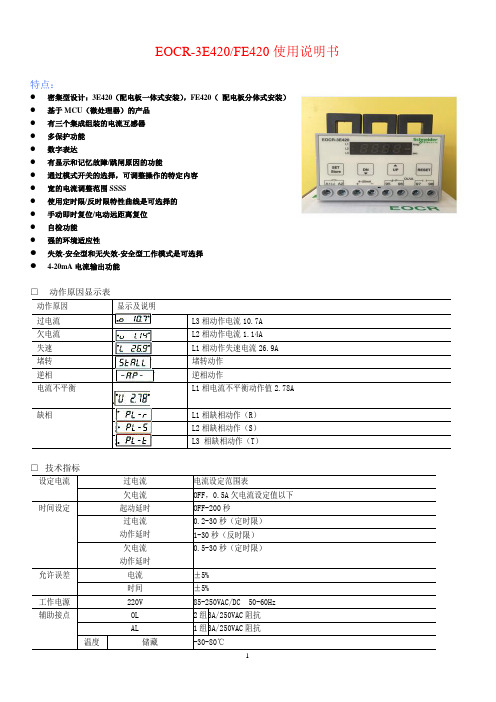
EOCR-3E420/FE420使用说明书特点:●密集型设计:3E420(配电板一体式安装),FE420(配电板分体式安装)●基于MCU(微处理器)的产品●有三个集成组装的电流互感器●多保护功能●数字表达●有显示和记忆故障/跳闸原因的功能●通过模式开关的选择,可调整操作的特定内容●宽的电流调整范围SSSS●使用定时限/反时限特性曲线是可选择的●手动即时复位/电动远距离复位●自检功能●强的环境适应性●失效-安全型和无失效-安全型工作模式是可选择●4-20mA电流输出功能□技术指标为使保护器能按要求起到保护作用,在其工作前应作必要的设置。
参照EOCR-3DM 典型接线图完成接线。
根据实际情况将功能开关选择在合适的位置上(参照上述说明)。
接通工作电源,按下述方法设置参数。
□ 过电流值设置按UP 位置。
这里0.5表示过电流值0.5A 。
若要改变此值,需按“SET/store ”键,然后按左右键调整,上述的值即可改变。
把这个值调整到电机铭牌上规定的额定值上(如无此值,推荐将此值放在电机实际运行电流的110-125%之间)。
再次按动“SET/store ”键,将该值存贮起来即可。
2.起动延时时间设置过电流值设置完成后,再按UP 键,即可看到显示。
dt 表示起动延时;10表示延时时间为10秒。
电机起动时其起动电流要达到电机额定运转电流的5-7倍。
电机的起动电流在其转数没有达到额定 转数的80%之前并不减少;当达到额定转数的80%以后起动电 流急剧下降至额定电流值(过电流设定值)以下。
电流变化曲 线与过电流设定值交叉点的时间就是电机起动延时时间D-TIME (参见右图)。
电机及负载类型不同,起动时间也不一样。
设定 时应根据具体情况在实际起动时间基础上多加2-3秒钟,设定范围为为1-200秒,设定时可在状态下按“SET/store ” 键后按左右键选择合适的时间值,再按“ SET/store ”键将设定值存贮即可。
电气灭弧限流式保护器使用说明书
产品使用说明书一、【产品概述】广东鑫轩电子科技有限公司是一家专业研发、生产电气灭弧限流式保护器及消防监控设备的创新型高科技企业,公司拥有一支科技创新型的产品研发、生产、销售队伍,掌握有多项专利技术。
公司研发成功的“电气灭弧限流式保护器”(以下简称“保护器”),可有效克服传统断路器、空气开关及传统监控设备的缺陷,其分断速度更快,使用寿命更长。
当发生短路故障时,能以微秒级速度快速实行限流保护;当发生过载电流故障时,能够实行延时限流保护;当环境温度或机内工作温度超限时,能执行超温限流保护。
该保护器能有效抑制短路电流的剧增,显著减少电气火灾危害,维护社会安全稳定。
二、【产品性能】1.微秒级短路限流保护功能产品能实时检测用电线路电流,一旦发生短路故障,能在150微秒内实现快速限流保护,有效抑制了因短路电流过大所引起的电气火灾危害。
2.当被保护线路的电流超过额定电流处于过载状态、且过载持续时间超过设定时间(3-60秒)时,保护器即可执行过载报警与限流保护。
3.当保护器工作环境温度或机内元件温度超过所设定温度值时,保护器即可执行超温保护功能。
4.保护器执行限流保护时,能发出声光报警指示。
5.保护器内置远程计算机数据接口,符合RS -485接口协议,可以将多台保护器与计算机联网,能够实现计算机实时监控、统计查询与追溯功能。
三、【产品应用场合】电气灭弧限流式保护器使用时应串接在电力分路开关后的用电线路中,能实时监测用电线路中电流故障并执行限流保护,是电气防火的保护神。
电气灭弧限流式保护器本产品可适用于各种用电场所,如学校、医院、寺庙、会展、宾馆、娱乐场所、商场、住宅、仓库及工厂等。
此产品亦可向石油、化工、汽车、轮船、航空等领域作电气防火的延伸开发。
四、【产品工作原理】图1所示的电气灭弧限流式保护器系统框图,表明了整个系统由以下几个单元构成:电流互感器1、检测单元2、温度传感器3、主控开关4、微处理器单元5、通信单元6、报警单元7以及辅助电源单元8。
产品使用说明书(GRZL智能漏电断路器)
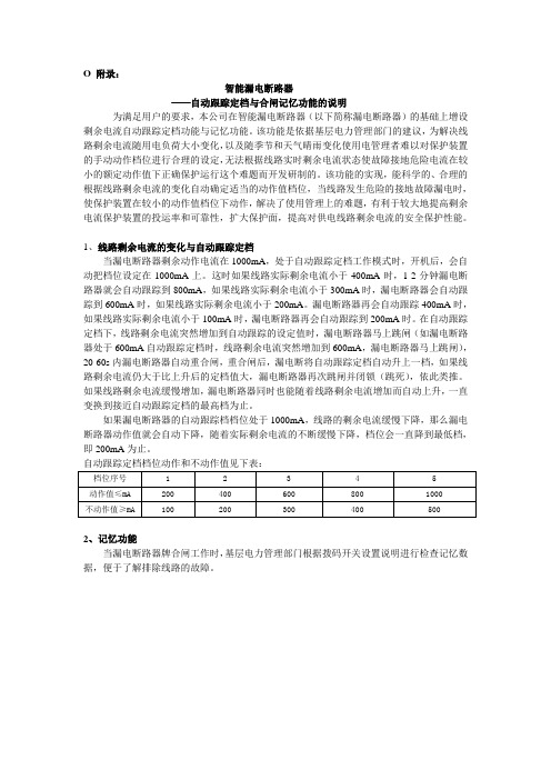
O 附录:智能漏电断路器——自动跟踪定档与合闸记忆功能的说明为满足用户的要求,本公司在智能漏电断路器(以下简称漏电断路器)的基础上增设剩余电流自动跟踪定档功能与记忆功能。
该功能是依据基层电力管理部门的建议,为解决线路剩余电流随用电负荷大小变化,以及随季节和天气晴雨变化使用电管理者难以对保护装置的手动动作档位进行合理的设定,无法根据线路实时剩余电流状态使故障接地危险电流在较小的额定动作值下正确保护运行这个难题而开发研制的。
该功能的实现,能科学的、合理的根据线路剩余电流的变化自动确定适当的动作值档位,当线路发生危险的接地故障漏电时,使保护装置在较小的动作值档位下动作,解决了使用管理上的难题,有利于较大地提高剩余电流保护装置的投运率和可靠性,扩大保护面,提高对供电线路剩余电流的安全保护性能。
1、线路剩余电流的变化与自动跟踪定档当漏电断路器剩余动作电流在1000mA,处于自动跟踪定档工作模式时,开机后,会自动把档位设定在1000mA上。
这时如果线路实际剩余电流小于400mA时,1-2分钟漏电断路器就会自动跟踪到800mA,如果线路实际剩余电流小于300mA时,漏电断路器会自动跟踪到600mA时,如果线路实际剩余电流小于200mA。
漏电断路器再会自动跟踪400mA时,如果线路实际剩余电流小于100mA时,漏电断路器再会自动跟踪到200mA时。
在自动跟踪定档下,线路剩余电流突然增加到自动跟踪的设定值时,漏电断路器马上跳闸(如漏电断路器处于600mA自动跟踪定档时,线路剩余电流突然增加到600mA,漏电断路器马上跳闸),20-60s内漏电断路器自动重合闸,重合闸后,漏电断将自动跟踪定档自动升上一档,如果线路剩余电流仍大于比上升后的定档值大,漏电断路器再次跳闸并闭锁(跳死),依此类推。
如果线路剩余电流缓慢增加,漏电断路器同时也能随着线路剩余电流增加而自动上升,一直变换到接近自动跟踪定档的最高档为止。
如果漏电断路器的自动跟踪档档位处于1000mA,线路的剩余电流缓慢下降,那么漏电断路器动作值就会自动下降,随着实际剩余电流的不断缓慢下降,档位会一直降到最低档,即200mA为止。
- 1、下载文档前请自行甄别文档内容的完整性,平台不提供额外的编辑、内容补充、找答案等附加服务。
- 2、"仅部分预览"的文档,不可在线预览部分如存在完整性等问题,可反馈申请退款(可完整预览的文档不适用该条件!)。
- 3、如文档侵犯您的权益,请联系客服反馈,我们会尽快为您处理(人工客服工作时间:9:00-18:30)。
ELR漏电保护器
■基于MCU的密集型设计
■用于电动机和配电系统的接地保护
■采用零序电流检测法
■TEST键提供了一个手动的自检功能
■接地电流和跳闸延迟时间是分别调整的
■绿色LED指示已建立电源,红色LED指示已跳闸
一、技术指标
二、操作说明
●TIME是跳闸延时旋钮,用来调节跳闸延迟时间。
●EARTH是漏电电流调节旋钮,用来调整检测漏电电流的大小。
●TEST是自动检测按键,常按TEST键,当时间超过TIME设定值时,继电器会动作跳
闸。
RESET是复位键,继电器动作跳闸后,按下RESET键继电器复位。
三、接线。
