Chapter 海洋管道的安装与施工
海上管线的安装和维修技术说明
海上管线的安装和维修技术说明随着海洋经济的快速发展和海洋资源的不断开发利用,海上管线成为极为重要的海洋产业基础设施之一。
海上管线的建设和维修涉及到多个领域的专业技术,包括海洋工程、材料科学、机械制造、电气工程等。
本文将从海上管线的设计、安装和维修等方面阐述相关的技术说明。
一、设计海洋环境的复杂性以及管线所需的各种性能要求决定了海上管线的设计过程十分复杂。
首先,需要确定沉管或浮管的使用方式,进而确定海底管线的敷设方式。
在此基础上,需要计算海洋环境下海上管线受力情况,进行管线结构设计和管壳厚度计算。
此外,还需要针对管线材料、防腐层等方面进行设计,以确保海上管线的使用寿命和安全性能。
二、安装海上管线的安装是海上管线工程的重要环节。
不同于陆上管道的安装,海上管线的安装环境复杂,操作难度较大。
在安装过程中,需要对管线进行预制、运输、装配等多个环节的精细安排。
为了减少海上管线的损失,需要专业装备、高端技术和训练有素的操作人员。
此外,在安装过程中还需要考虑海上天气、海况等外部因素,以确保工作的安全性和高效性。
三、维修海上管线的使用寿命长,但在长期使用过程中也需要进行维修。
一旦海上管线发生漏气、断裂等问题,需要迅速采取措施进行修复,以保障管线的正常使用。
海上管线维修工作需要在恶劣的海洋环境下进行,因此需要特别考虑安全风险。
对于一些较为简单的维修工作,可以采用外部修复方式;而对于一些需要维修的部位较为深入的情况,则需要进行内部维修。
此时需要通过智能机器人等技术手段进行远程操作,在不危及人体安全的情况下实现内部维修。
四、新技术应用随着科学技术的不断发展,海上管线的设计、安装和维修等方面也出现了多种新的技术应用。
例如,通过先进的三维激光扫描技术可以更加精确地测量管线受力情况;通过无人机技术可以快速获取海上工程的相关数据和图像,从而实现更加高效的工作流程。
此外,通过智能机器人和VR技术,可以在安全、便捷的操作环境下进行管线维修,达到更好的维修效果。
海洋管道的施工-讲义
3、管道的铺设-Reel Lay
根据卷筒 铺管船的设计和 水深 ,卷管可以 用 S-lay or J-lay 方法 来 安装 .卷筒铺管船可以有垂直或者 水平 的 卷筒 。
水平的卷筒铺管船在浅水到中等水深使用托管架和S-lay铺设管 道.
3、管道的铺设 -顶管法
4、管道的试压和试运转
管道的试压包括:
在加工制作现场对组装的管段进行试压,检验焊口 的质量;
在管道铺设后,管沟回填前的全管道试压。
试验压力一般为管道最大工作压力的1.25~1.5 倍。 海底管道的试运转:按使用要求和设计标准逐项测 试, 以便制定管道工艺操作规程。
1、对防腐层的基本要求
• S-lay • J-lay • Reel lay
3、管道的铺设-S-lay
S-lay的发展经历了四个阶段: 第一代 S-lay 铺管船主要是平底驳船,应用于浅水和内
陆水域 第二代 S-lay 铺管船主要是平底驳船,但具有4-14个的
锚链来定位。 第三代 S-lay 铺管船是半潜式的,应用锚链定位。 第四代 S-lay 铺管船是半潜式的,应用动力定位。
2、保温层、加重层
保温层 • 对于双层管结构的海底管道,内外间设置保温层, 泡沫塑料是较好的隔热保温材料。 • 有喷涂和浇注两种施工方法。
加重层 • 为满足设计负浮力的配置和防止施工工程中对绝缘防 护层的损伤,常在防腐绝缘层外包加重层。 • 加重层一般是含钢筋的混凝土或水泥砂浆。 • 制作方法:人工涂抹;立模浇筑;表面喷漆;离心旋 制;预制安装。 • 海底管道加重层的质量控制,主要指混凝土的强度、 密实度、吸水率和加重层的尺寸等。
海洋工程中的海底管道安装技术
海洋工程中的海底管道安装技术是海洋工程领域中的重要一环。
海洋工程包括了石油、天然气、水净化和电力传输等领域的开发利用,而海底管道则是这些领域中不可或缺的一种输送工具。
本文将从海底管道的设计、铺设和维护等方面,探讨。
首先,海底管道的设计是安装的关键。
设计师需要考虑到海底环境的复杂性和多变性,如水流、波浪、海底地理条件等。
同时,还要考虑管道所需承受的压力、温度和腐蚀等因素。
为了保证海底管道的稳定性和可靠性,设计师需要运用各种技术手段,如深水测量、地质勘探和数值模拟等,提前研究海底环境,并根据实际情况设计合理的管道方案。
其次,海底管道的铺设是安装的核心环节。
铺设过程中需要用到各种工具和设备,如海上起重设备、管道浮标、定位系统等。
如果海底地理条件较为复杂,需要采用先进的技术手段,如水下机器人或无人潜艇等,将管道准确地铺设在海底。
此外,还需要进行管道的连接和压力测试,以确保管道的完整性和耐压性。
最后,海底管道的维护是确保使用安全的重要环节。
海底环境恶劣,管道易受腐蚀和泄露的影响,因此需要定期进行巡检和维修。
目前,一些先进的技术已被应用于海底管道的维护中,如机器人巡检、遥感监测和防腐涂层等。
这些技术可以帮助工程师及时发现管道的问题,并采取相应的措施进行修复,确保管道的安全运行。
除了以上提到的设计、铺设和维护等关键技术,海洋工程中的海底管道安装还涉及到安全管理和环境保护等方面。
海底管道的安装往往需要进行多国合作,涉及国际海域和国内海域等不同区域,因此需要制定相关的国际标准和规范。
此外,海洋生态环境的保护也是不可忽视的,需要考虑管道对海洋生态系统的影响,并采取相应的环境保护措施。
综上所述,是复杂而重要的。
设计、铺设和维护等环节都需要技术人员的精心研究和处理。
随着科技的发展,未来将会更加先进和高效,为海洋资源的开发利用和环境保护做出更大的贡献。
海工场地管道安装施工方案
本工程为海工场地管道安装工程,主要内容包括海底管道、海底管线终端、海底管道连接件、海底管道支撑结构等。
工程地点位于我国某海域,施工环境复杂,海底地形多变,对施工质量及安全要求较高。
二、编制依据1. 国家相关法律法规及标准规范;2. 工程设计文件;3. 施工合同及现场实际情况。
三、施工程序和要求1. 施工准备阶段(1)对施工现场进行勘察,了解海底地形、地质、水文等情况;(2)组织施工队伍,明确施工任务及责任;(3)编制施工组织设计,明确施工工艺、施工顺序、施工质量控制点等;(4)准备施工所需材料、设备、工具等。
2. 施工实施阶段(1)海底管道铺设1)根据设计要求,对海底管道进行预制;2)采用专用设备进行海底管道铺设,确保管道铺设质量;3)对铺设后的管道进行检测,确保管道铺设符合设计要求。
(2)海底管线终端安装1)根据设计要求,对海底管线终端进行预制;2)采用专用设备进行海底管线终端安装,确保安装质量;3)对安装后的海底管线终端进行检测,确保安装符合设计要求。
(3)海底管道连接件安装1)根据设计要求,对海底管道连接件进行预制;2)采用专用设备进行海底管道连接件安装,确保安装质量;3)对安装后的海底管道连接件进行检测,确保安装符合设计要求。
(4)海底管道支撑结构安装1)根据设计要求,对海底管道支撑结构进行预制;2)采用专用设备进行海底管道支撑结构安装,确保安装质量;3)对安装后的海底管道支撑结构进行检测,确保安装符合设计要求。
3. 施工验收阶段(1)对施工过程进行跟踪检查,确保施工质量;(2)对施工完成后的管道进行检测,确保管道符合设计要求;(3)组织验收,对验收合格的项目进行移交。
四、管道组成件检验1. 管道材料:对管道材料进行检验,确保材料质量符合设计要求;2. 管道连接件:对管道连接件进行检验,确保连接件质量符合设计要求;3. 管道支撑结构:对管道支撑结构进行检验,确保支撑结构质量符合设计要求。
海底管道安装分析及铺设工艺
海底管道安装分析及铺设工艺张捷,陈伟鹏(中交海洋建设开发有限公司, 天津 300457)[摘 要] 海底管道是海洋石油开发装备的重要组成部分,国内外海底管道建设市场巨大。
本文从管道分类入手,介绍海底管道基本情况,按照工程建设顺序,研究从设计到施工管道建设过程。
在海底管道铺设分析中介绍了管道安装分析方法及校核准则,举例说明了海底管道分析过程。
介绍了海底管道施工方法及施工工艺流程,合适的施工方法可以保证管道长期使用安全,同时可节约施工费用及施工工期。
有关理论分析可供同行参考,也可为类似工程提供借鉴。
[关键词] 海底管道;安装分析;校核准则;S-LAY铺管法;弃管与回收作者简介:张捷(1986—),男,湖北人,2009年毕业于天津大学港口、海岸及近海工程专业,硕士研究生,高级工程师,从事海洋工程设计与工程管理工作。
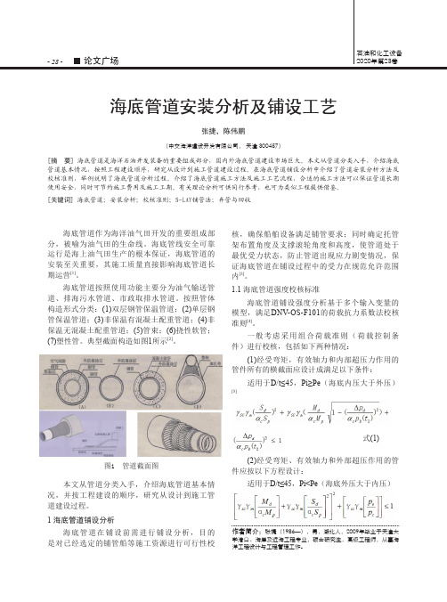
图1 管道截面图海底管道作为海洋油气田开发的重要组成部分,被喻为油气田的生命线。
海底管线安全可靠运行是海上油气田生产的根本保证,海底管道的安装至关重要,其施工质量直接影响海底管道长期运营[1]。
海底管道按照使用功能主要分为油气输送管道、排海污水管道、市政取排水管道。
按照管体构造形式分类:(1)双层钢管保温管道;(2)单层钢管保温管道;(3)非保温有混凝土配重管道;(4)非保温无混凝土配重管道;(5)管束;(6)挠性软管;(7)塑性管。
典型截面构造如图1所示[2]。
本文从管道分类入手,介绍海底管道基本情况,并按工程建设的顺序,研究从设计到施工管道建设过程。
1 海底管道铺设分析海底管道在铺设前需进行铺设分析,目的是对已经选定的铺管船等施工资源进行可行性校核,确保船舶设备满足铺管要求;同时确定托管架布置角度及支撑滚轮角度和高度,使管道处于最优受力状态,防止管道出现应力剧变情况,保证海底管道在铺设过程中的受力在规范允许范围内[3]。
1.1 海底管道强度校核标准海底管道铺设强度分析基于多个输入变量的模型,满足DNV-OS-F101的荷载抗力系数法校核准则[4]。
海底管线工程施工方案

海底管线工程施工方案一、前言海底管线工程是一项复杂而重要的工程,对于海洋环境的保护以及海洋资源的开发都有着重要意义。
本文将就海底管线工程的施工方案进行详细描述,包括施工流程、施工方法、安全管理、质量控制等方面。
二、施工准备1. 项目概况本项目是一项海域深度约1000米的海底管线工程,需要从陆地到海底铺设一条直径为1米的管线,全长约100公里,主要用于输送天然气。
2. 施工组织为了保证施工的顺利进行,我们将成立一个专门的施工队伍,包括工程经理、施工人员、安全员、质量检验员等。
每个岗位的责任和工作内容都将明确规定。
3. 人员培训在施工前,我们将为施工人员进行必要的培训,包括海上作业技能、安全意识培训、急救技能培训等,确保他们具备必要的技能和知识。
4. 装备准备我们将根据施工的需要准备好必要的设备和工具,包括海底管道敷设设备、船只、浮标、安全装备等,以确保施工的进行。
5. 施工区域调查在施工前,我们将通过水下探测技术对施工区域进行详细调查,了解海底的地形、水深、地质情况等,为后续的施工工作做好准备。
6. 施工方案编制在对施工区域进行调查后,我们将根据实际情况编制详细的施工方案,包括敷设路线、施工方法、安全措施等内容。
三、施工流程1. 海底管线敷设首先,我们将利用专业的海底敷设船舶将管线运输到预定敷设区域。
然后,通过定位系统确保管线准确地敷设在海底。
2. 海底管线焊接在管线敷设完成后,我们将利用专业的焊接设备对管线进行焊接,确保管线的完整性和密封性。
3. 海底管线安装在管线焊接完成后,我们将对管线进行安装,包括连接管件、固定管线等,确保管线的稳定性和可靠性。
4. 海底管线测试在管线安装完成后,我们将对管线进行必要的测试,包括水压测试、泄漏测试等,确保管线的质量和安全性。
5. 海底管线保护为了保护管线免受外界影响,我们将在管线上安装必要的保护设施,包括防腐层、保护壳等,确保管线的长期稳定运行。
四、施工方法1. 船舶敷设法我们将采用专业的海底敷设船舶进行管线敷设,利用船上的定位系统确保管线的准确敷设。
海底管道铺管施工安装方法研究

海底管道铺管施工安装方法研究摘要:海底管道铺管施工安装是海洋工程领域的一项重要技术,用于将各种管线系统铺设在海底地形中。
海底管道施工的安全和有效性对于保障海洋资源开发和利用具有重要意义。
因此,研究海底管道铺管施工的安装方法是至关重要的。
基于此,以下对海底管道铺管施工安装方法进行了探讨,以供参考。
关键词:海底管道;铺管施工;安装方法;研究引言海底管道铺管施工是一项关键的海洋工程技术,广泛应用于油气开发、能源输送、海洋通信等领域。
它是将管道系统安全并有效地铺设在海底地形中的关键过程,直接影响到海洋工程的可靠性和持续运营。
1海底管道铺管施工的重要性海底管道铺管施工是海洋工程中的重要环节,具有以下几个方面的重要性:1.能源供应:海底管道是输送海洋能源资源(如石油、天然气)到陆地或其他地点的主要通道。
通过海底管道的铺设和施工,能够实现可靠、安全的能源供应,满足人们对能源的需求。
2.经济价值:海底管道的建设和运营可以带来巨大的经济价值。
海洋资源开发和海底管道的铺设促进了相关产业的发展,推动经济增长和就业机会的创造。
3.环境保护:海底管道作为能源输送的重要通道,能够减少陆地上的温室气体排放和污染物的排放,对环境保护具有重要意义。
通过有效而可持续的海底管道铺设施工,可以减少对陆地生态系统的破坏,保护海洋生态环境。
4.地缘政治稳定:海底管道的铺设和运营涉及不同国家和地区之间的合作和关系。
通过海底管道的建设,能够促进国际能源合作和地缘政治的稳定,减少地区冲突和能源供应的不确定性,维护国家和地区的利益。
5.科技创新:海底管道铺设施工需要使用先进的技术和设备,促进了相关科技领域的创新。
在海底管道施工的过程中,需要解决各种复杂问题,包括海洋环境下的布置、防腐保护、安全监测等方面,推动了相关技术的发展和创新。
2海底管道铺管施工安装问题分析海底管道铺管施工安装是一个复杂的过程,可能面临以下一些常见问题:1.地形复杂性:海底地形可能非常复杂,存在山脉、峡谷、沉积物等不同的地质条件。
海洋工程中海底管道施工与维护技术研究

海洋工程中海底管道施工与维护技术研究海洋工程是指在海洋中进行各种工程活动的学科领域,其中海底管道施工与维护技术是海洋工程中的一项重要研究内容。
海底管道是连接陆地与海洋的通道,用于输送油气、水源、电力等重要资源,对于国家的能源安全和经济发展起到了至关重要的作用。
本文将着重探讨海洋工程中海底管道施工与维护技术的研究进展和应用。
在海底管道施工方面,技术研究主要集中在以下几个方面:首先是管道敷设技术。
目前主要采用的是潜水敷设和自由敷设两种方式。
潜水敷设是通过潜水员在水下进行操作,将管道连接好后,利用船只将管道下沉到海床上,然后通过液化气体将管道埋设在海床上。
自由敷设则是将管道从船上往海底放下,然后由海水的浮力将其沉入海底。
此外,还有研究自动化敷设技术,利用机器人进行管道敷设,提高施工效率和管道质量。
其次是管道连接技术。
由于海洋环境的特殊性,管道连接需要具备耐高压、耐腐蚀和耐温变等特点。
目前主要采用的连接方法有焊接、机械连接和胶接。
其中,焊接是最常用的方法,可以保证连接的牢固性和密封性。
机械连接则利用特殊的接头将管道连接起来,具有重复使用的优势。
胶接是一种相对较新的连接方法,利用特殊的胶黏剂将管道连接,具有灵活性和抗震性。
第三是管道维护技术。
由于海洋环境的变化和管道的长期使用,管道的维护十分重要。
主要包括巡检、修复和防腐等方面。
巡检是通过ROV(遥控操作无人潜水器)等设备进行的,利用摄像头等装置对管道进行定期检查,及时发现并修复管道的破损。
修复技术主要包括局部修复和整体更换两种方式,局部修复是对管道的某一部分进行修复,而整体更换是将损坏的管道进行更换。
防腐方面主要采用喷涂防腐、涂覆防腐和阴极保护等技术,以延长管道的使用寿命。
海洋工程中海底管道施工和维护技术的研究不仅关乎国家能源安全和经济发展,对于保护海洋生态环境也有重要意义。
一方面,海底管道的敷设和维护需要克服海底地形复杂、水下能见度低等困难,通过技术手段减少不必要的破坏和浪费。
海底管道铺设工程施工方案

海底管道铺设工程施工方案一、前言海底管道铺设工程是一项具有高技术含量和大规模工程的工程项目。
海底管道铺设工程的施工方案是指在工程设计完成后,根据实际情况和技术要求,对海底管道的具体施工工艺、工序、施工设备、施工流程和施工方法等进行详细的规划和安排,以保证工程施工顺利进行,质量达标,安全可靠。
二、海底管道铺设工程概况海底管道铺设工程是指将管道从陆地或者海上的设备经济地铺设到海底,并通过现场连接、沉管敷设、液体敷设等方式完成,从而实现海上沉管和陆地设施的连接。
海底管道的主要用途包括输送天然气、石油、煤气等能源,以及输送海水、淡水、废水等。
海底管道铺设工程是一项具有高技术含量和大规模工程的工程项目,需要进行详细的工程规划和设计。
在海底管道铺设工程中,首先需要进行海底的实地勘察,了解海底的地质情况、水深情况、地形特点等情况;其次需要进行管道材料的选择和管道设计;再者需要进行海底管道的施工方案设计和施工计划的制定;最后需要进行海底管道的施工实施。
三、海底管道铺设工程施工方案设计3.1 海底管道材料的选择在海底管道铺设工程中,管道的材料选择对于工程的安全和持久性至关重要。
一般情况下,海底管道的材料可以选择高密度聚乙烯材料、玻璃钢材料、碳素钢材料等。
在材料的选择上需要考虑管道的工作环境、运输介质、使用寿命、成本等因素,尽量选择具有耐腐蚀、高强度、抗压力好的管道材料。
3.2 海底管道的设计海底管道的设计是海底管道铺设工程的关键环节。
在设计过程中,需要进行水深、地质情况、输送介质等情况的详细调查分析,确保海底管道设计符合实际情况,满足工程的使用要求。
3.3 海底管道的敷设方式海底管道的敷设方式包括液体敷设、沉管敷设、现场连接等。
在敷设方式的选择上需要考虑海底情况、管道长度、输送介质等因素。
一般情况下,液体敷设可以适用于浅水域,而沉管敷设适用于深水域。
3.4 海底管道的施工设备海底管道的施工设备是海底管道铺设工程的重要保障。
水下钢管安装技术说明
水下钢管安装技术说明水下钢管安装技术是一项应用广泛的海洋工程技术,主要用于油气管道、海底电缆等海洋工程结构的安装。
该技术应该由专业的海洋工程师或钢管安装专家进行操作,具体操作步骤如下:一、选址钢管安装的第一步是选址。
在实际操作中,选址的过程要考虑多方面因素,包括海底地形、海洋生物和地质条件等,以及管道的长度、材料和通道等要素。
选址的过程需要进行巨大的工程测量和地质勘探,根据实际条件选择最合适的位置进行钢管安装。
二、设计钢管安装的第二个阶段是设计。
进行设计时需要考虑到选址时所建模型,钢管的质量和材料,操作的步骤,水文环境,以及钢管的固定方法等因素。
设计之前要进行多次复核和测试,确定系统的可行性。
同时还需要考虑到海洋环境的变化和其他因素,以使钢管能够更稳定的运行。
三、钢管安装钢管安装是整个流程中最重要的部分,在这个过程中需要进行钢管的放置和固定。
在实际操作中,由于海洋环境和钢管所处的位置的不同,手动安装和机械安装的过程也不同。
在钢管拖曳和路线规划后,可以使用水下机器人或深海潜水器来进行跟随和安装钢管。
完成钢管安装之后要进行钢管的密封和固定工作。
四、测试安装完成后需要进行测试工作,测试工作包括对钢管的密封效果、固定效果、钢管行进的速度和通道的自由流等情况进行测试。
这有助于发现问题并及时进行修复。
同时,还可以通过测试收集数据,对分析结果进行分析和优化,使整个系统达到更高的效率和稳定性。
五、维护保养维护保养是一个系统的、长期的过程,需要对钢管系统进行定期的检查和维护,以确保系统的长期稳定和可靠性。
总结水下钢管安装技术是一项综合性较高的海洋工程技术,需要专业的工程师。
在钢管安装的整个过程中,需要考虑到多种因素,包括地形、材料、环境等等。
同时还需要进行多次测试和复核,以确定系统的可靠性和高效性。
在钢管安装完成后还需要进行测试和维护保养,以确保钢管系统的长期稳定和可靠性。
海底管线安装施工程序及技术分析
Lu =H
23起始锚 回收 _ 在海 管铺 到一定 长度 就需要 回收起 始锚 .回收起 始锚时海管 的 长度需 要精 确地计 算 . 根据 海底 地质 调查结 果 , 根据 地 质得 出相应 其 中: L为起始缆 的长度 : u 为安全系数 : 的摩擦 系数 . 计算 出多长 海管 的摩擦力 可 以和张 紧器的 7 O吨拉力 平衡 。 H为海域水 深 : 海管在水 中海床对海管的摩擦 力 , 力计算公式 为 : 拉 按 D V规范 u 1 . N 取 0 所以本项 目采办的起始缆的长度为 10 米 。 00 本次铺设 采用的是起始 锚的方式 . 在施 工前应核 算张力 . 并准 备 F N = L ( .) 2 4 合适 的拉力锚 . 本项 目为 了防止在做拉力测 试时发生 移锚 . 以本项 所 式 中: N为海管单位长度重量 ; 目采用 了抛双锚 的办法 为海底摩擦系数 ; () 1 当起 始缆头在 1 3 0 米水深的时候 , 应用计算程 序计算起始 缆 L为着 泥海管 长度 : 在下放至海底后 的水平伸长为 2 米。 2 计算结果得到铺设 7 公里的海管后 。 海管的摩擦力就可 以满足张 () 2 当起始缆头在 8 米水深的时候 . O 应用计算程序计算起 始缆在 紧器张力 . 以这时就可 以将起始锚 回收上来。 所 下放至海底后 的水平伸长为 2 米 l () 1首先 A T将锚漂 收起 , H 将锚上 面的 2 0 的钢缆解 下 , 后 5米 然 顺着钢缆将第 一个锚 收起后 , 回到 S M C 。 送 E A 1 () 3 当起始缆头在 6 米水深的时候 . 0 应用计算程序计算起始缆在 将锚漂再次放到水中 , 下放至海底后的水平伸长为 1 米。 9 经过多个数据 的计算 . 起始缆在下 () 2 然后再次 回来将浮漂捞起 , 将第二个锚收 回来 , 最后开始绞起 放至海底后的水平伸长为 2 1米 始缆 . 经过 计算需要绞 到 8 0 0 米长钢缆 后 , 切断钢缆 将剩余 2 0 0 米钢 在现场施工时 , 拉力测试遵循如下操作 : 缆放 回水 中. 以防止收缆过 长造成起始 缆受力将海管拖 动 , 造成海 管 ( )先 将 SA C 1 E M 1船 尾 停 在 k0 2 p. 4处 .将 起 始 缆 连 接 在 封头坐标 的改变 0 S M C 船 的 s 锚缆上 . EA1 6 在缓慢施加 15吨力后 . 0 发现船 和 D A都 M 24终止铺设 . 没有发生移动 . 然后维持 15 0 吨的张力下 3 分钟后 . O 就可 以证 明双锚 在终止铺设时 .同样需要提前对海管终止端着泥点进行计算 , 以 可以提供足够的抓地力 保证终 止端落 在设 计位 置 , 计算 方法是使 用 p en 软件 , i le pi 在计算 完 () 时 G R 2这 P S显示船 尾在 K 00 4处 , P .2 由于起始 缆连接 在船 上 毕后需要核算海管的长度 , 确保海管终止端落在设计 ( 下转第 4 2页 ) 3
chapter08 海洋管道和立管安装(英文)
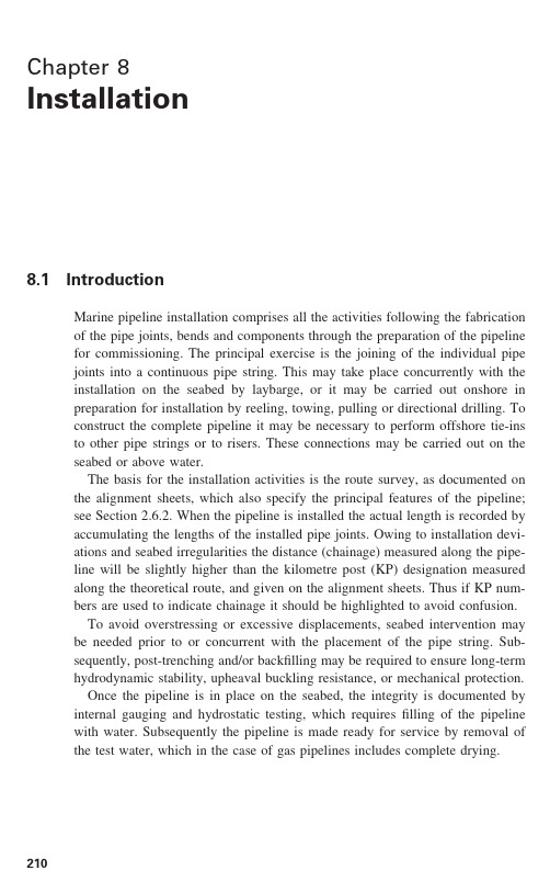
Chapter 8Installation8.1IntroductionMarine pipeline installation comprises all the activities following the fabrication of the pipe joints, bends and components through the preparation of the pipeline for commissioning. The principal exercise is the joining of the individual pipe joints into a continuous pipe string. This may take place concurrently with the installation on the seabed by laybarge, or it may be carried out onshore in preparation for installation by reeling, towing, pulling or directional drilling. To construct the complete pipeline it may be necessary to perform offshore tie-ins to other pipe strings or to risers. These connections may be carried out on theseabed or above water.The basis for the installation activities is the route survey, as documented on the alignment sheets, which also specify the principal features of the pipeline;see Section 2.6.2. When the pipeline is installed the actual length is recorded by accumulating the lengths of the installed pipe joints. Owing to installation devi-ations and seabed irregularities the distance (chainage) measured along the pipe-line will be slightly higher than the kilometre post (KP) designation measured along the theoretical route, and given on the alignment sheets. Thus if KP num-bers are used to indicate chainage it should be highlighted to avoid confusion.To avoid overstressing or excessive displacements, seabed intervention may be needed prior to or concurrent with the placement of the pipe string. Sub-sequently, post-trenching and/or backfilling may be required to ensure long-term hydrodynamic stability, upheaval buckling resistance, or mechanical protection.Once the pipeline is in place on the seabed, the integrity is documented by internal gauging and hydrostatic testing, which requires filling of the pipeline with water. Subsequently the pipeline is made ready for service by removal of the test water, which in the case of gas pipelines includes complete drying.2108.2Seabed intervention8.2.1GeneralModifications of the natural seabed that may be needed include:•soil replacement to improve the foundation properties, for example, to pre-vent the pipeline from sinking into soft mud;•trenching to reduce the actions from waves and current;•protection of existing pipelines or cables in connection with crossings;•provision of supports for riser bases, spools, etc.;•reduction of free span heights to reduce the forces due to overtrawling;•smoothing of the pipeline profile to reduce the length of free spans or prevent contact pressures that could damage the coating or dent the pipe steel.Spans that are unacceptable in the unstressed, airfilled condition must be recti-fied before installation of the pipeline (pre-lay intervention). Other free span rectification may be postponed until after the pipe string has been placed (post-lay intervention).For fatigue verification it is common industry practice to require that no more than 10% of the allowable damage ratio (see Section 6.4.6) be reached duringthe temporary installation phases, which include a period in which the pipeline is empty on the seabed and a period in which it is waterfilled. As the free spans are typically larger in the former case, the accumulated damage can be reduced by flooding the pipeline shortly after installation, thus obviating the need for pre-lay span rectification.Once the pipeline is ready for operation it will be known what fatigue damage may have occurred during installation (pipelaying) and for how long the free spans will have been exposed in the empty and in the waterfilled conditions (it is not necessarily the same pipeline sections in the three cases). The remaining fatigue life of the free spans in the operating condition can then be calculated, and post-lay free span rectification carried out if necessary.Trenching and backfilling after pipe string installation are treated in Section8.7, whereas pre-lay seabed intervention is discussed below.8.2.2Pre-trenchingThe construction of pipeline trenches or the removal of outcrops to reduce free spans are normally achieved by dredging. Depending upon the type and hardness of the seabed soil different dredger types (bucket dredger, cutter-suction dredger, etc.) are deployed. In shallow waters the dredging may be carried out from jack-up platforms, or even fixed structures. In extreme cases blasting with explosivesSeabed intervention211212InstallationAs the trench must be sufficiently wide to receive the pipeline, pre-trenching is an attractive option only for pipelines installed by towing or pulling, including shore approaches, or for laying in very shallow water or across mud plains, where trenching is needed to gain access for the pipelay vessel. Such near-coast areas are also the most environmentally sensitive, and pre-trenching is likely to be subject to severe restrictions, including those for the disposal of the dredged material.8.2.3Pipeline supportsAs an alternative to the removal of seabed material a suitable support for the pipeline may be created by rock dumping, either along the entire section affected, or – more likely – as isolated gravel berms.The size of the individual stone or gravel particles shall be adjusted to the environmental conditions to ensure that the material will not be removed by wave and current action. The rock dumping may be performed by split barges, but much more economical use of material is obtained by using a rock dumping vessel equipped with a fall pipe, through which the material may be placed over the pipeline with great accuracy. Fall pipe dumping is routinely performed at water depths exceeding 300m, the vertical tolerance being ± 200mm.Pre-lay free span supports will have to be made sufficiently wide to cater for the pipelay tolerance as well as the horizontal tolerance on rock dumping, whichis greater when the gravel berm cannot be related to a fixed object (e.g. thepipeline) on the seabed. Thus there is an economic incentive to use post-lay rather than pre-lay intervention; see Section 8.2.1 above.Unacceptable free spans may also be reduced by structural supports, estab-lished on the seabed during the installation. Proprietary systems have been devel-oped where the pipeline can be supported at variable height above the seabed, and the supports can be placed by divers or diverless vehicles etc. This may be the only alternative for very large water depths, where neither dredging nor rock dumping is viable. Isolated supports made from grout bags or similar may also be installed under the pipeline to prevent it from sinking deeply into very soft seabed soil such as organic mud.It may also be necessary to establish lateral supports to guide the pipeline in the horizontal plane to achieve the desired lay radius if the lateral soil friction is insufficient; see Section 6.3.6. Rather than gravel berms, such counteracts may take the form of structural elements that can be retrieved and reused. A typical design would be a hollow concrete cylinder, possibly provided with a steel skirt that penetrates the seabed to enhance the lateral resistance. To increase the sup-port capacity further the cylinder can be filled with gravel.8.2.4Crossingstrenching of the pipeline. The crossing of live pipelines and cables, on the other hand, calls for special measures, including negotiations with the third party owners. To avoid damage to any of the installations the lines should be separated by a suitable material, and often the relevant authorities will have requirements for the crossing design. DNV OS-F101 specifies a minimum separation of 0.3m.The existing cable/pipeline may already be trenched into the seabed, or it may be allowed and feasible to carry out such trenching. In that case is suffices to lay the new pipeline on top. As it cannot then be trenched, it may have to be protected by post-lay rock dumping or similar.In most cases, however, the existing cable or pipeline will be lying on the seabed and cannot be touched. Then it is necessary to engineer a pipeline cross-ing using rock berms, mattresses, grout bags or similar, so the new pipeline can be laid across without damage to the existing one, and the entire crossing covered, if required.8.3Pipe assembly8.3.1GeneralThe individual pipe joints are assembled into pipe strings by girth welding, i.e.circumferential butt welding. Strict requirements are specified for welding con-sumables, welding procedures, welder qualifications, as well as inspection and testing, in order to ensure optimum quality of the pipeline.The welding can be carried out offshore during pipelaying (on the laybarge or pipelay vessel), often referred to as marine welding. Pipe strings may also be made onshore for subsequent offshore installation by reeling, towing, pulling and directional drilling. This is then referred to as site or shop welding.Onshore fabrication of the pipe string includes the field joint protection, and for towed or pulled pipelines it also includes the attachment of sacrificial anodes. It is also possible to insert a thermoplastic liner for internal corrosion prevention and, basically, two methods are used. A liner with an outer diameter slightly greater than the pipeline bore may be pulled into the string through a diameter reduction device, and when the tension is removed the liner relaxes back to a close fit.Alternatively, a liner with a diameter slightly less than the pipeline bore may be pulled in, and subsequently expanded by pressurised hot water. Owing to the lower friction, the latter method can be used for pipe strings up to 1000m in length. However, as mentioned in Section 6.6.3, for hydrocarbon pipelines special measures must be taken to prevent diffused gases from collapsing the liner in the case of depres-surisation. Consequently, liners are mostly used for water lines. The corrosion protection properties may be enhanced by injecting cement paste between the liner and the steel pipe. An even thickness of the cement layer is ensured by thePipe assembly213214InstallationThe installation of a long pipeline often involves the assembly of several pipe strings. On a reel barge a new reel is joined to the pipeline in much the same way as for laybarge installation, usually after recovery of the previous string from the seabed. Assembly of two pipe strings left on the seabed may be accomplished by either mechanical coupling devices or by welding; see Section 8.6.4. The weld-ing operation may be carried out above surface (davit lift), or subsea (hyperbaric welding). In the latter method the welding is carried out in a pressurised habitat placed over the ends of the pipeline that are to be joined. Mechanical coupling devices may be substituted for welding in such cases; for deep water this is the only option.8.3.2Girth weldingJoining the pipe by girth welding consists of circumferential welding. The abutting pipe ends are prepared to facilitate easy welding according to the welding process to be used. The processes considered for modern girth welding of pipelines are:•friction welding;•explosion welding;•electron beam welding;•laser welding;•submerged arc welding, SAW;•shielded metal arc welding, SMAW (using cellulosic or low hydrogen basic electrodes);•gas metal arc welding, GMAW.The first four methods have not yet made it beyond the novelty stage, whereas the latter three are used extensively.Pipeline girth welding is covered by a number of standards, such as:•API 1104;•BS 4515;•BS 7910;•CSA Z184.These standards are devoted to all aspects of welding, including non-destructive testing and acceptance criteria for such testing. The acceptance criteria are basically written down as ‘G ood Workmanship Standards’, such as API 1104, and the defect acceptance is essentially derived from radiographic images of the weld, i.e. length, width and type of defect. The workmanship criteria can be ‘transformed’ into ultrasonic inspection by assuming that the acceptable height of the defect corresponds to the typical height of a single pass in multipassit is being extrapolated to mechanised welding the acceptance criteria will be better based on a ‘Fitness for Purpose’ concept, or rather on so-called engineer-ing criticality assessment (ECA). This is already incorporated in the above-mentioned standards under certain conditions, but more recently the EN 1594 and the DNV OS-F101 deal in great detail with ECA based acceptance criteria, as does the European Pipeline Research Group: Guidelines for defect acceptance levels in transmission pipeline girth welds. In Section 8.3.3 below an example is given of an ECA based upon BS 7910.To increase the efficiency in pipe laying it is customary to pre-make double joints in a separate welding operation, either onshore or – most likely – on the laybarge, and then to add these double joints to the pipeline in a semi-continuous process in the so-called ‘firing line’. The double joint welding is usually fully mechan-ised. There is normally sufficient time to conduct the welding and to perform inspection, testing and possible repair welding before entering into the final production line. The preferred welding process depends on the linepipe material. For carbon steel linepipe materials the standard choice is SAW, as it is a reason-ably fast and reliable welding process, but it may be combined with root and hot passes using mechanised G MAW. For corrosion resistant alloys the welding process will be some form of semi- or fully mechanised GMAW. Carbon steel with internal lining or cladding of corrosion resistant alloys may use internal or externally applied GMAW in the root, with SAW to fill up the weld gap.In the firing line the normal choice today will be mechanised G MAW, but SMAW is also used. Until 1970, marine girth welding was dominated by SMAW using cellulosic electrodes to weld vertically down at a high deposition rate. Their main drawback is a high propensity to hydrogen cracking when the welds cool down, but careful control of welding procedures enables control of the cracking at least up to a strength grade suitable to weld X65 pipes. For higher grade steels, or if overmatching welds are required, the next step up is the use of basic covered electrodes and, recently, also fuse cored electrodes. This enables high strength weld material to be used without the risk of hydrogen cracking. The demand for higher productivity led to the development of mechanised GMAW. Not only is it possible to cut down the welding time considerably, but it also removes the risk of hydrogen cracking and allows a broad spectrum of high strength weld metals to be used. Mechanised welding generates only a few random defects, but lends itself to producing repetitive and systematic flaws if it is not continuously monitored and checked. Feed-back to the welder needs to be fast in order to avoid extensive repairs, thus mechanised welding has also provided a challenge to the non-destructive testing of welds. Today mechanised welding goes hand in hand with automated ultrasonic inspection and special acceptance criteria to give a complete or holistic approach to girth welding. The firing line weld is made with a root pass and one or more hot passes before the filler passes are deposited. There are several proprietary mechanised weldingPipe assembly215216InstallationFigure 8.1Field joint welding on laybarge (photo: DONG A/S)the amount of deposited weld metal (and hence welding time). Some of the pro-cesses make use of an internally deposited root pass, while others are completely single-side welded. Typical semi-automatic field welding is shown in Figure 8.1.The firing line welds are inspected and tested before leaving the barge. If non-acceptable defects are detected, the line is pulled back and the weld is repaired by either a complete cut out or an approved local weld repair procedure.It is very important to consider in advance not only the type of inspection and testing to use to ensure the weld integrity, but also what the acceptance criteria will be for the selected testing method.Visual inspection is still used widely today as it offers a rapid check for arc burns/strikes, weld crown irregularities, undercuts, bead concavity, etc. If pos-sible it should also be carried out from the internal side.X-ray inspection detects volumetric defects such as porosities, and will also pick up inclusions, burn through, root bead concavity and lack of penetration. If planar defects are lined up in the direction of the x-rays they will also be detected.Manual ultrasonic testing using conventional pulsed echo probes can pick up most of the defects, except porosities and root bead concavity. The method is very time consuming because it is necessary to manipulate the probes extens-ively to cover the entire weld volume, and it is necessary also to use severalTo cut down the inspection time the ultrasonic testing has been mechanised. Several probes are used simultaneously with different angles and different depths of focus. In this way it is possible to tailor-make the inspection to specific weld bevel geometries. By also using phased array probes and time of flight diffrac-tion techniques it is possible to cover the entire weld zone and all type of defects with a high probability of detection in one go around the weld, bringing down the inspection time to a few minutes, and with instant feedback of the examina-tion result to the welder. These highly sophisticated inspection processes are dependent on calibration and validation prior to on-line inspection, and also on frequent calibration during the inspection work.The industry has over many years worked to the ‘Good Workmanship Stand-ard’ using visual inspection and radiography (x-ray). The workmanship criteria are based on the weld quality that can be expected from a good welder (on a good day) and working to these criteria the repair rate is generally below 5%. The experience gained (or rather the lack of girth weld failures experienced) justifies that pipelines exposed to (mainly) static stresses below the specified minimum yield of the pipe material are checked against such ‘workmanship’criteria.For pipelines exposed to plastic strain during pipe lay or during subsequent installation processes, such as trenching/ploughing or davit lifting above the sea surface, or pipelines exposed to excessive free spanning with high bending strainsand possible fatigue due to vortex shedding, etc., the workmanship criteria may not be sufficient. In such cases the acceptance criteria should be derived from fracture mechanics based engineering critical assessments, taking into considera-tion such factors as:•the mechanical properties across the welds (undermatching or overmatching weld strength);•the local geometry of the weld;•the amount of strain;•the strain rate;•the stress/strain amplitude;•the possible influence from the external and internal environments in terms of either active corrosion or hydrogen uptake.Based on the outcome of the ECA it is then possible to define position, length and depth of acceptable defects, and to select the non-destructive test method(s) that will find non-acceptable, harmful defects with a satisfactory probability of detection.The DNV OS-F101 provides comprehensive coverage of pipeline welding and non-destructive testing requirements.Hyperbaric welding, inspection and testing should follow the same principlesPipe assembly217218Installationconditions duplicating the actual physical conditions in the habitat and in the pipes. The hyperbaric welds should be made with the same equipment and by the same welders/weld operators as the test welds. The weld inspection and non-destructive testing should be made in a such a way and by such methods that will result in the same or better probability of detection of harmful defects. Weld repairs are only allowed if the weld repair procedures are qualified and validated through the same tests as for the girth weld.8.3.3Engineering criticality assessment (ECA)Most codes and standards request that acceptance criteria for non-destructive testing (NDT) of pipeline girth welds are based on an engineering criticality assessment (ECA) when the accumulated plastic strain resulting from installation and operation is above 0.3%. The process of developing such acceptance criteria is illustrated in Figure 8.2.Basically it requires an ECA and qualification of the NDT equipment and procedures in order to develop the acceptance criteria. The engineering critical assessment provides a set of curves describing the limits for critical defect sizes,and the qualification gives information about the detection and sizing capabilities of the NDT system. The ECA may be performed using BS 7910 to determine critical defect sizes. If there are in-service conditions inducing failure by fatigue or unstable crack growth the assessment shall be at Level 3, otherwise a normal assessment, Level 2A, is sufficient.The ECA is based on actual material specifications and actually measured fracture toughness properties (crack tip opening displacement (CTOD), critical stress intensity factor, K IC , or J-integral) of the weld metal, heat-affected zone Qualification and validation Assessment of NDT system Practical demonstration and/or technical justification of:Detection capabilities Sizing capabilitiesAcceptance criteria ECA partQ&V partInteraction criteria ECAMaterial-specific information Mechanical propertiesFracture toughnessProject-specific informationPipe dimensionApplied strain, etc.and base metal from the welding procedure qualification. Due consideration should be given to the possibility that some pipes may have lower fracture toughness than the pipe used in welding procedure qualification testing. Also, repeated repair welding must duly be considered as it may impede the fracture toughness considerably, as may high heat input welding methods used for double jointing outside the firing line.An example of ECA is shown below in order to illustrate the influence of fracture toughness values on the critical defect sizes. The data for applied strain and CTOD-value are maximum and minimum values, respectively, therefore no safety factors have been used in the calculations. The maximum value for applied strain is assumed to include all stress and strain concentration factors. Design basis and assumptions: preliminary ECAPipe inner diameter, Di729mmNominal wall thickness, t17.5mmMaterial API 5L X65Young modulus, E207000MPaPoisson coefficient0.3SMYS450 MpaSMTS520 MPaStrain at ultimate stress23%Minimum weld material fracture toughness,(here crack tip opening displacement)0.2–0.5mmMaximum applied strain0.5%Embedded defects2mm from surfaceNotationa defect depthc defect half lengthd equal to a for surface defects, and 2a for embedded defectsK stress intensity factorKmatmaterial toughness measured by stress intensity factorKr fracture ratio of applied elastic K value to KmatMm,bstress intensity factor, membrane/bendingMkm,bstress magnification factor, membrane/bendingPbprimary bending stressPmprimary membrane stressQbsecondary bending stressQmsecondary membrane stressRmmiddle radius for pipeSrload ratio of applied load to flow strength loadLrload ratio of applied load to yield strengthPipe assembly219220InstallationΦmathematical factor (2nd order elliptical integral)βc /R mδcrack tip opening displacement (CTOD)δI applied CTODδmat material toughness measured by CTOD method δr fracture ratio using CTOD parameters εu strain at fracture εy strain at yield η1−d /tρplasticity correction factor σapplied stressσnom applied nominal stress σf flow strengthσK effective net section stress σu tensile strengthσYlower yield strength or 0.2% proof strengthMethodology applied to calculate critical defect size The steps in the calculation method are as follows.The assessment curve is given by:δr =K r =(1−0.14L r 2)[0.3+0.7 exp(−0.65L r 6)]where L r,max =1.15 (taken from BS 7910:1999 Figure 11a)δδδρr mat=+1δσπσI y =()Y a E2ρ is given in BS 7910 annex R.Y σ=(Y σ)p +(Y σ)s (Y σ)p =1Φ(M km M m P m +M kb M b P b )(Y σ)s =1Φ(M m Q m +M b Q b )M m and M b are determined according to BS 7910 Annex M3.Φ is a correction factor defined in BS 7910 Annex M, formula M9a /2c <0.5; Φ=[(a /c )1.65 (1+1.464)]0.50.5<a /2c <1; Φ=[(c /a )1.65 (1+1.464)]0.5The effective net section stress σK for a surface circumferential defect under pressure is determined according to Kastner et al . (1981) (see also Miller 1988,p. 291):σσηπβηπηηβK nom [ ( )]( )sin =−−+−⎧⎨⎩⎫⎬⎭121The plastic collapse ratio is determined by:L r =σK / σyPrimary stressThe primary axial load of the pipe is given by the limit strain level, εm . The corresponding stress level, σm , is found using the Ramberg-Osgood curve for the relevant material:εσασm m m y =⋅+⎛⎝⎜⎞⎠⎟⎡⎣⎢⎢⎤⎦⎥⎥−()11n EThis stress level is used as the primary membrane stress P m .The values for α and n for the material are determined by the formulae:αεσ=⋅−y yE1n E E ln ( ) ( ) ln =⋅−⋅−⎡⎣⎢⎤⎦⎥⎛⎝⎜⎞⎠⎟εσεσσσu u yy y u Secondary stressThe residual stress due to the welding is assumed to be the lesser of:σy and14. −⎛⎝⎜⎞⎠⎟σσk f σy(from BS 7910 7.3.4).Q mPipe assembly 221222InstallationTable 8.1Calculated critical defect heights as function of defect lengths and CTOD-value Defect typeDefect Defect height (mm)length (mm)d =0.2d =0.3d =0.4d =0.5Surface breaking 20 2.2 4.9or interacting302 3.75 6.640 1.93 4.4 5.450 1.83 2.9 4.1 4.970 1.78 2.7 3.8 4.4100 1.7 2.6 3.3 4.1150 1.64 2.43 3.8200 1.6 2.3 2.9 3.4Embedded20 5.15811.613.930 4.55 6.38.19.840 4.3 5.87.18.350 4.2 5.5 6.657.7704 5.2 6.17100 3.8 4.9 5.7 6.4150 3.6 4.5 5.35.92003.454.34.95.5h e i g h t , m mlength, mm76543210Calculated critical defect heights for given defect lengthsTable 8.1 and Figures 8.3 and 8.4 illustrate the defect length, defect height and the corresponding fracture type for different defect types calculated for different CTOD-values.The curves illustrate that the better the material is in terms of fracture tough-ness, the larger the defect that can be tolerated in the welds. In the ideal case theh e i g h t , m mlength, mm1514131211109876543210Figure 8.4Critical defect heights for embedded defectsacceptable defect size is the same as the critical defect size. In reality acceptable defects should be chosen to be smaller than critical ones to cover for uncertain-ties due to the following.Defect sizing capabilitiesA state of the art NDT technique allows for very accurate height sizing of defects. The tolerance on the height sizing capability of the applied NDT system is verified in the qualification of the equipment, and can therefore be accounted for when establishing a set of allowable defect sizes.Probability of detection aspectsA semi-automated welding technique combined with a state of the art NDT Pipe assembly223224Installationthe expected defects, ensures a very high probability of detection of the critical defects.In addition to this, the defect population distribution is not known at the time when the acceptance criteria are developed, thus the probability of occurrence of defects cannot be quantified up front. This problem is addressed by imposing a quality assurance that focuses on the accumulated defect length within welds and within a number of consecutive welded butt joints. These limits ensure that the quality of the welding remains high, and they have, in principle, nothing to do with the integrity of the weld.8.3.4Field joint coatingAfter welding the linepipe steel, the weld area and the adjacent coating cut-back is protected by field joint coating. Corrosion protection is normally achieved with tape wrapping or heat shrink sleeves; if both the adjacent pipe joints are provided with concrete coating or insulating coating a suitable infill material is applied to the field joint area, to create a continuous pipe string. A typical field joint on a concrete coated pipe is shown in Figure 8.5.Welds to pipe joints or bends that are not concrete coated, as well as to com-ponents (weld neck flanges, valves, isolation couplings, etc.), are normally pro-vided with heat shrink sleeves, or if produced in a shop they may be coated with an epoxy paint system, similar to that used on the corresponding component; see Section 7.9.1.If the adjacent pipe joints or components are provided with fusion bonded epoxy coating (FBE, see Section 7.4.5) the same coating may be applied to the。
海底管道气体运输的管道施工与安装技术
海底管道气体运输的管道施工与安装技术随着全球能源需求的增长,海底管道已成为一种常见且高效的能源输送方式。
海底管道气体运输能够满足远离陆地的能源获取需求,为世界各地提供持续的能源供应。
在实际的海底管道气体运输过程中,管道的施工与安装是至关重要的环节。
本文将重点探讨海底管道气体运输的管道施工与安装技术。
管道施工是指将海底管道在水下进行实质性的制造和安装工作。
在施工阶段,从设计到投入使用,需要经历一系列复杂的步骤和工序。
首先,需要进行海底地质勘探,确定管道的最佳布置方案。
接下来,进行海底管道的设计,并制定详细的施工计划和工艺流程。
然后,进行管道材料的采购和预制,包括钢管的生产和外防腐层的施工。
接下来,进行海底管道的敷设,包括施工船只的调配、定位、吊装和铺设等工作。
最后,完成管道的测试和调试,确保其正常运行。
海底管道气体运输的管道安装技术是指将已制造完成的海底管道进行安装和连接的工作。
在安装阶段,需要充分考虑海底地质条件、海洋环境、工程要求和安全因素。
首先,进行海底管道的检查和验收,确保其质量符合要求。
接下来,进行管道的搬运和定位,确保管道能够准确地铺设在指定位置。
然后,进行管道的连接与焊接,采用专业的焊接技术和设备,确保连接的牢固和密封性。
最后,进行管道的锚固和保护,以防止管道的移动和损坏。
在海底管道气体运输的施工与安装过程中,还需要特别关注以下技术与措施。
首先,海底地质条件的调查与评估是至关重要的,可以帮助确定最佳的海底管道布置方案。
其次,施工船只的选择和使用对于工程的顺利进行至关重要,需要考虑到船只的吨位、工作能力和动态定位系统等因素。
此外,管道的防腐和防护技术也是必不可少的,可以采用外防腐层、内衬材料、防火涂层等措施,保护管道不受海洋环境的侵蚀。
另外,考虑到天气和海洋环境的不确定性,需采取相应的安全措施,包括海上救生设备和防护装置等,以应对突发事件和事故。
在海底管道气体运输的管道施工与安装过程中,还需要充分考虑环境保护和可持续发展的要求。
海底管道铺设工程施工中的施工工艺与工序优化
海底管道铺设工程施工中的施工工艺与工序优化海底管道铺设工程是一项复杂而关键的工作,对于油气开发、海洋资源开发以及海底通信等领域具有重要意义。
在海底环境的复杂性和不可预知性下,施工中的工艺与工序的优化显得尤为重要。
本文将探讨海底管道铺设工程施工中的施工工艺与工序优化,以期在保证工程质量的前提下提高施工效率与安全性。
一、施工工艺优化1. 测量与勘探海底管道铺设工程前期的测量与勘探是关键步骤。
通过精确测量海底地形、水文、地质等数据,可以为铺设工程提供必要的信息,预测可能遇到的问题并进行合理规划。
优化测量与勘探技术,采用先进的设备和方法,可以提高数据准确性与工作效率,降低施工风险。
2. 设计与规划海底管道铺设工程的设计与规划应综合考虑海底地质、环境因素、施工周期等多种因素,并进行全面评估与合理选择。
优化设计与规划可以提高工程的可行性和经济性,降低材料与能源的消耗,减少环境影响,并最大程度地保障施工的安全性。
3. 工程准备在施工前,对所需要的设备、材料以及人力资源进行充分准备。
采购合适的设备和材料,并进行充分的质量检验,确保在施工现场可以顺利进行工作。
优化工程准备可以提高施工效率和质量,减少工程延期和额外成本。
二、施工工序优化1. 预处理工序在实际施工中,预处理工序是关键的一步。
包括传输管道、连接件、脚手架等的安装,海底地面的平整处理等。
通过对海底地面进行平整处理,可以减少管道安装过程中的难度和不稳定性,提高施工质量。
此外,在预处理工序中,对管道进行质量检查和保养,以减少后续施工中的故障和损坏。
2. 管道铺设工序管道铺设工序是整个施工过程的核心。
在进行管道铺设时,需要考虑管道连接、抗涌阀的安装、管道接缝的密封等方面。
通过优化工序,采用高效的铺设设备和工艺,可以提高施工速度和质量,减少相关的风险和成本。
3. 海底固定工序海底管道铺设后,需要进行海底固定工序。
通过安装支架、固定器等设备,将管道牢固地固定在海底,确保其稳定性和安全性。
Chapter 5 海洋管道的安装与施工

卷筒铺设
卷筒式铺管在陆地将管道接长,卷 在专用滚筒上,然后送到海上进行铺 设。
卷筒式铺管效率高、费用低、可连 续铺设、作业风险小
卷筒法所用滚筒有水平放置和竖直 放置两种,为减小管道卷绕后的塑性 变形滚筒直径一般比较大。
受到铺管船尺寸和滚筒直径 的限制,卷筒式铺管法中的管 道直径较小。
卷筒铺设
5.2.2 铺管船法铺设管道及立管
铺管船铺设法
最常用的海上安装方法之一,包括: S型铺设 J型铺设 卷筒式铺设
5.2.2 铺管船法铺设管道及立管
铺管船铺设法
铺设海底管道的最常用的方法是铺管船法。 目前有3种不同类型的铺管船,包括传统的箱型铺管船、 船型铺管船以及半潜式铺管船,按定位形式又可分为锚 泊定位和动力定位两种形式铺管船。 最常用的四种类型的铺管船:常规铺管船、半潜式铺 管船、动力定位式铺管船和卷筒式铺管船。
1)整体立管安装:只能在浅水区域运用目前很少采用 2)分体立管安装:广泛运用于各种水深 A 悬挂立管
立管预制 起吊、翻身 悬挂 B 膨胀弯连接
水下测量 膨胀弯预制 起吊、下水 法兰组对、加力
主要设备:浮吊船、驳船、三用拖轮、膨胀弯角度测 量仪、空气潜水设备(浅水)、饱和潜水设备(深水)
浅海立管的安装-立管预制
2.平台没有预装构件
吊装过程分析: (1)强度分析: (2)吊点布置:
5.1.3浅海登陆上岛立管的安装
1.浅海登陆上岛立管的安装 对大多数非岩基的平缓岸滩,多采用挖沟埋放办法用绞车牵 引管道,使其海底拖入管沟。
当岸滩为基岩或砾石时,可采用爆破法施工,之后用底拖法 将牵引管段牵引入沟,牵引定位,然后用压块、锚杆或用护 管堤等措施稳定立管。
浅海立管的安装悬挂立管
取水海里管道施工方案
取水海里管道施工方案引言取水海里管道施工方案是指为了从海洋中取水,并将水输送到供水系统中,所需进行的管道安装和施工工作。
本文将介绍取水海里管道施工的准备工作、施工步骤和注意事项。
准备工作在开始取水海里管道施工之前,需要进行一系列准备工作以确保顺利进行。
以下是准备工作的主要步骤:1. 管道设计在进行取水海里管道施工之前,需要进行管道设计。
管道设计包括确定取水点的位置、管道长度和直径,以及管道的材料选择等。
设计人员需要考虑水的质量、流量、海底地形等因素,以确保管道能够稳定地输送水。
2. 材料采购根据管道设计方案,需要进行相应的材料采购。
常用的管道材料包括钢管、塑料管和玻璃纤维管等。
在进行材料采购时,需要考虑材料的质量和强度,以及适应海水环境的耐腐蚀性能。
3. 施工队伍组建为了进行管道施工,需要组建一个专业的施工队伍。
施工队伍需要包括管道安装工、焊接工、试压工等各类专业人员。
同时,还需要配备必要的施工设备和工具。
4. 安全评估在进行取水海里管道施工之前,需要进行安全评估。
安全评估包括评估施工现场的安全风险,确定相应的安全措施,如设立警示标志、安装护栏等,以确保施工过程中的安全。
施工步骤取水海里管道施工包括以下几个主要步骤:1. 海底勘察在进行施工之前,需要进行海底勘察以确定管道的敷设路径。
海底勘察需要使用声纳等设备来获取海底地形和地质数据,以选择最佳的管道敷设路径。
2. 管道敷设根据海底勘察结果,可以确定管道的敷设路径。
管道可以通过直接控制潜水员进行敷设,或者使用敷设船进行敷设。
在敷设过程中,需要保持管道的水平和均匀敷设,同时避免管道的弯曲和损坏。
3. 管道连接在管道敷设完成后,需要进行管道连接。
连接管道可以使用焊接、螺纹连接或者橡胶密封等方式。
连接管道时需要确保连接牢固,并进行必要的试压测试以确保密封性能。
4. 试压和检测在管道连接完成后,需要进行试压和检测。
试压可以通过泵入高压水或气体来检测管道的强度和密封性能。
- 1、下载文档前请自行甄别文档内容的完整性,平台不提供额外的编辑、内容补充、找答案等附加服务。
- 2、"仅部分预览"的文档,不可在线预览部分如存在完整性等问题,可反馈申请退款(可完整预览的文档不适用该条件!)。
- 3、如文档侵犯您的权益,请联系客服反馈,我们会尽快为您处理(人工客服工作时间:9:00-18:30)。
5.2.2 铺管船法铺设管道及立管
铺管船铺设法
普通船型式铺管船吃水深度相对较深,适合需要承载 较重设备或高起吊力时使用。
半潜式铺管船通常是非自航式,但也可采用动力定位 系统。半潜式铺管船船型巨大,作业线多设置在船的中 央,其最大的特点就是稳定性强,可以在比较恶劣的环 境中以及深海海域施工作业。
拖曳铺设
• 管道或立管束在岸上制造(垂直和平行)。 • 在车间里可以获得很好的焊接质量。 • 灵活的制造进度表与海上进度表没有冲突。 • 可使用非常廉价的拖船。 • 可使用各种各样的拖曳方法(水面、水面下、CDTM、底部
拖曳)。 • 可安装长度有限制。 • 需要三艘拖船用于安装(但是廉价)。 • 由于它非常大的重力所以在海床上非常稳定(不需挖沟)
第一遍焊缝焊接(打底-氩弧焊)
stringer bead (argon welding)
J 型铺设
20世纪80年代以来为了适应铺管水深不断增加而发展起 来的一种铺管方法。 J型铺管法目前主要有2种:一种是钻井船J型铺管法;另 一种是带倾斜滑道的J型铺管法。 在铺设过程中,借助于调节托管架的倾角和管道承受的 张力来改善悬空管道的受力状态,达到安全作业目的。
J 型铺设 J 型铺设
焊形在驳船上进行, 用专门的管卡和定位对 中装置,以确保对口的 焊接质量。
对对焊接头加工完毕, 把连成一体的L形立管吊 起徐徐放入海底,并用 管子卡将立管固定在平 台腿柱或弦杆上。
2.平台没有预装构件
外立管在水下连接的步骤: 首先用铺管船的高架吊吊起 立管并沿导管架垂直放至海底, 用立管卡把立管固定在导管架 上; 然后驳船锚泊定位,通过固 定在立管弯头处的定滑轮把管 道联到立管弯头处,再由潜水 员将立管与管道焊接起来。
5.水面下拖法: •此方法与浮拖法相似,只是为了避免波浪对管道的影响, 利用浮筒将管道悬浮在距海面一定深度下。相对于浮拖法, 此方法可使管道的运动和疲劳损伤都大大减小。
6.复合式拖法:
•复合式拖法是几种拖航方法的组合,根据离海岸距ห้องสมุดไป่ตู้及水 深的不同,综合采用多种拖管法,从而充分发挥各种拖管 法的优势。
第五章 海洋管道的安装与施工
5.1 立管的安装 5.2 海洋管道及立管的铺设方法 5.3 管道施工铺设中的典型受力分析
5.2 海洋管道及立管铺设方法
海底管道包括立管管道铺设方法主要有: 海底管道铺设方法包括: ① 拖曳法(浮拖法、近底拖法、底拖法); ② 铺管船铺设法(S型铺管法、J型铺管法和卷筒 式铺管法) ③ 围堰法
海底管道工程
第1章 海底管道概述 第2章 管道工艺计算 第3章 管道稳定性分析 第4章 管道的强度设计 第5章 海底管道的施工 第6章 海底管道腐蚀与防护
第五章 海洋管道的安装与施工
5.1 立管的安装 5.2 海洋管道及立管的铺设方法 5.3 管道施工铺设中的典型受力分析
5.1 立管的安装
牵引头的安装
pulling head installation
牵引头的安装
pulling head installation
牵引头的安装
pulling head installation
海底管道铺设
Initiation head
fit-up and alinement
preheating
3.离底拖法:
•利用浮筒和压载链将管道悬浮在距海床一定高度上,再由拖 轮拖航。这种方法适用于海底地形已知情况,需要的拖力很小, 疲劳损伤也较小。
4.控制深度拖法:
•管道被控制在水面以下一定深度悬浮着,由水面拖轮牵引。 拖航时水对压载链的拖曳力产生一种升力,减小了管道水 下重量。拖速越大,拖缆与垂直方向夹角也越大。这种方 法在国外应用最多,研究也最广泛。
• 管道在岸上的受控环境中焊接, 然后连续地缠绕在浮式装置上直 到全部完成或达到最大容量。
• 张力减少很多,因此与S 型铺设 相比可以更好地控制。
• 对可处理的覆层类型有限制。
• 存在局限性,通常是由关系到装 载能力的容积引起。
• 需要岸上基地的支持。 • 典型铺设速度可高达1 千米/小
时,平均约600 米/小时。
当拖曳到安装停放区域后,集束立管降低速度,从拖船放 出钢丝来控制立管的下放速度,放置到海床。 一旦集束立管稳定在距海床2.5 米的状态时,所有的拖船开 始放出钢丝,将张力减到最小。
然后,集束立管准备进行海底之上的拖曳。集束立管从安 装停放区域被牵引到目标区,在那里浮箱被注水和回收。 牵引操作通过GFC 平台顶部的绞盘提供拉力和减少来自拖 船的反拉力。
2.平台没有预装构件
吊装过程分析: (1)强度分析: (2)吊点布置:
5.1.3浅海登陆上岛立管的安装
1.浅海登陆上岛立管的安装 对大多数非岩基的平缓岸滩,多采用挖沟埋放办法用绞车牵 引管道,使其海底拖入管沟。
当岸滩为基岩或砾石时,可采用爆破法施工,之后用底拖法 将牵引管段牵引入沟,牵引定位,然后用压块、锚杆或用护 管堤等措施稳定立管。
S型铺设 铺设施工时,管道呈S形状而得名
托管架stinger 垂弯区sagbend
S 型铺设
S型铺管法一般需要在船艉部增加一个很长的圆弧形托管 架,管道在重力和托管架的支撑作用下自然的弯曲成“S’’形 曲线。 S型铺管法是目前技术最成熟、应用最广泛的深水铺管法。 1998年建成的“Solitaire”号代表了最新一代的S型铺管船, 该船载重量达22 000 t,采用动力定位系统,已经完成了大 量海底管道铺设工程,保持着2 775 m 的海底管道铺设水深 最大纪录。
ROV 用于监视J型管入口、立管底座和牵引拉头。必须保 证在通过ROV 监控的操作期间立管底座既不发生旋转也不 触礁。当立管底座进入目标盒子后牵引操作停止。立管系统 被观测。立管牵引到位后,临时悬挂夹具从GFC 平台顶部安 装到立管上,这样立管可以在密封壳体上静止。
安装实例-拖拉法,用于登陆段
• 焊接在浮式装置上进行,由于在 一个场所进行,速度慢。
• 管道脱离角度非常接近于垂直, 所以张力较小。
• 主要用于深水。 • 不需船尾托管架。
• 所有操作都在垂直方向完成,稳 定性是一个难题。
• 典型铺设速度是1-1.5 千米/天。
J型铺设示意
Technip公司J型和 卷筒(Reeling)铺设船
示意图
5.2.5 海洋管道施工步骤
组装托管架 管道的转运和准备 安装牵引头 海底管道铺设 海底管道与平台的连接 挖沟和掩埋
组装托管架
托 管 架 组 装
托 管 架 吊 装
托 管 架 入 水
管道的转运和准备
管道的转运和准备
bench slope machining
Area for welding preparation
1)整体立管安装:只能在浅水区域运用目前很少采用 2)分体立管安装:广泛运用于各种水深 A 悬挂立管
立管预制 起吊、翻身 悬挂 B 膨胀弯连接
水下测量 膨胀弯预制 起吊、下水 法兰组对、加力
主要设备:浮吊船、驳船、三用拖轮、膨胀弯角度测 量仪、空气潜水设备(浅水)、饱和潜水设备(深水)
浅海立管的安装-立管预制
5.2.1 拖曳法铺设管道及立管
拖曳法(牵引法铺设技术)
在近海浅水区铺设海底管道时,通常采用拖管法。 拖管法中的管道一般在陆上组装场地或在浅水避风水域 中的铺管船上组装成规定的长度,然后用起吊装置将管 道吊到发送轨道上,再绑上浮筒和拖管头,用拖船将管 道拖下水,按预定航线将管道就位、下沉,最后将各段 管道对接,完成管道铺设全过程。
S 型铺设
屈曲传播
S 型铺设
• 管道在浮式装置上使用单或双接头进行装配。 • 需要一个可达100 米长的托管架; • 必须处理非常高的张力; • 有水深限制,因为: 更大水深=更长的托管架=稳定性丧失 更大水深=更高的张力=更大的风险 典型铺设速度约3.5 千米/天。
当水深增加,可采取J型铺设方式。
(2)铺管船辅助安装法
由潜水员将通过J形管的钢缆系在离平台100多米处的铺 管船拖管架的拖管头上,然后从平台上牵引,铺管船逐渐 放松管子,可将管道拉过J形管而成立管。
在铺管船安装完立管后,以此为铺管的始端,继续进行 铺管。立管直径不宜大于500mm.
2.平台没有预装构件
浅水立管的安装:
先将管道吊出海面, 与立管弯头对焊成一体, 呈L形。
5.2.1 拖曳法铺设管道及立管
拖曳法(牵引法铺设技术)
目前,拖管法又可分为以下几种方法: ① 浮拖法(surface tow)、 ② 水面下拖法(below surface tow)、 ③ 离底拖法(off-bottom tow)、 ④ 底拖法(bottom tow)、 ⑤ 控制深度拖法(CDTM) ⑥ 复合式拖法(combined tow)。
42
43
5.2.3 围堰法铺设管道及立管
围堰法铺设
通过围堰铺设管道时,不受波浪海流等环境荷载影响, 施工过程简便。
但围堰修建时施工难度较大,费用很高,工程量大, 工期长。
5.2.4 安装设备概述及安装实例 安装设备概述
5.2.4 安装设备概述及安装实例 安装实例-拖曳方法
某拖曳安装工程:2000 年在北海挪威海域实施的一个集束 立管系统工程。对于其它采用拖曳方法安装的管道和立管都 是完全适用的。
浅海立管的安装悬挂立管
浅海立管的安装膨胀弯起吊下水
5.1.1内立管的安装
施工的关键问题: 1)管道牵引至预定位置定位; 2)内立管的垂直段与海底管道连接.
5.1.2海上钢平台的立管安装
1.平台装有预装构件
5.1.2海上钢平台的立管安装
1.平台装有预装构件
(1)直接牵引法 正向牵引:从海洋平台把牵 引钢缆通过J形管将海底管道 硬拉过J形管。 反向牵引:从海底管道与立 管连接处进行