可调节流阀说明书.
Festo GRLA 优化流量调节阀门系列说明书
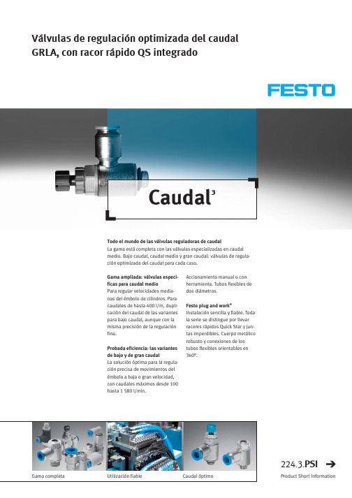
Válvulas de regulación optimizada del caudal GRLA, con racor rápido QS integradoCaudal³Accionamiento manual o con herramienta. Tubos flexibles de dos diámetros.Festo plug and work ®Instalación sencilla y fiable. Toda la serie se distingue por llevar racores rápidos Quick Star y jun-tas imperdibles. Cuerpo metálico robusto y conexiones de los tubos flexibles orientables en 360°.Gama ampliada:válvulas especí-ficas para caudal medioPara regular velocidades media-nas del émbolo de cilindros. Para caudales de hasta 400 l/m,dupli-cación del caudal de las variantes para bajo caudal, aunque con la misma precisión de la regulación fina.Probada eficiencia: las variantes de bajo y de gran caudalLa solución óptima para la regula-ción precisa de movimientos del émbolo a baja o gran velocidad,con caudales máximos desde 100hasta 1580 l/min.Todo el mundo de las válvulas reguladoras de caudalLa gama está completa con las válvulas especializadas en caudal medio. Bajo caudal, caudal medio y gran caudal:válvulas de regula-ción optimizada del caudal para cada caso.Gama completaUtilización fiableCaudal óptimo224.3.PSIProduct Short InformationFesto AG &Co.KGRuiter Strasse 8273734 EsslingenInternet Tel. ++49 (0)711 347-0 Fax ++49 (0)711 347-2144E-mail service_international@060405R e s e r v a d o e l d e r e c h o d e m o d i f i c a c i ónVálvulas de regulación optimizada del caudal GRLA, con racor rápido QS integradoLas nuevas variantes de caudal optimizado GRLA-QS-(RS-)MF-D Selección más amplia con la serie GRLA ampliada: válvulas reguladoras de caudal medio (MF) en ejecución metálica.Las válvulas de estrangulación y antirretorno se utilizan para regular el caudal con el fin de ajustar la velocidad del émbolo de un cilindro en avance o retro-ceso. Dependiendo del tipo de válvula, pueden regularse de modo preciso movimientos len-tos, medios o rápidos.Características de la variante de caudal medio:•Válvula reguladora mediante estrangulación del escape •Mayor caudal que en las variantes de bajo caudal •Accionamiento manual o con destornillador (ranura)•Ejecución metálica robusta y fiable•Montaje sencillo y rápido mediante sistema para soltar racores Quick Star•Conexión para tubos flexibles:QS 6, 8Comparación de tamaños y cau-dalesEn la tabla se comparan los tamaños de diversas válvulas reguladoras (bajo caudal, caudal,medio, gran caudal) recurriendo al ejemplo de la variante G1/8con tubo con diámetro exterior de 6 mm. En el diagrama se puede apreciar el caudal corres-pondiente.Comparación de caudales: tipo de referencia G1/8, tubo con diámetro exterior de 6 mmComparación de dimensiones:tipo de referencia G1/8, tubo con diámetro exterior de 6 mmGRLA-..-QS-..-RS-D GRLA-..-QS-..-RS-BGRLA-..-QS-..-RS-MF-DTipoB D H Lmín Lmáx GRLA-1/8-QS-6-RS-D 12,513,832,641,445,3GRLA-1/8-QS-6-RS-MF-D 17,836,648,952,8GRLA-1/8-QS-6-RS-B1317,936,148,853,2TipoB D H L 1mín L 1máx L 2d G GRLA-1/8-QS-6-MF-D 12,517,836,6––3661/8GRLA-1/8-QS-8-MF-D 14,539,68GRLA-1/8-QS-6-RS-MF-D 12,536,648,952,8–6GRLA-1/8-QS-8-RS-MF-D14,539,68HL DDBBBDLLHHHBDL 2L 1GGDBHddGRLA-1/8-QS-..-MF-D GRLA-1/8-QS-..-RS-MF-DRosca G1/8" para tubo flexible con diámetro exterior de 6 mmGRLA-1/8-QS-6-RS-BGRLA-1/8-QS-6-(RS)-MF-DGRLA-1/8-QS-6-(RS)-DGiros o posición del tornillo de regulaciónC a u d a l n o m i n a l n o r m a l q n N [l /m i n ]。
节流阀说明书
铸钢节流阀Cast steel Throttle valve使用说明书Operation Manual双达阀门股份有限公司Shuangda valve co., ltd一、用途和性能规范 Usage and specification1.本产品适用于水、油品、蒸汽等管路上做调节用,具有流阻小、启闭灵活、寿命长、安全可靠等优点。
2.适用温度:-29~425℃。
Service temperature: -29~425℃.3.常温下实验压力按下表规定:Test pressure under normal temperature二、采用的主要标准 Standards adopted①设计制造按GB12236-89、API600的规定;Design and Manufacture: GB12236-89、API600②试验和检查按GB/T13927、API598的规定;Test and Inspect: GB/T13927、API598③法兰尺寸按ANSIB16.5、GB/T9113、JB/T79的规定;Flanged Dimension: ANSIB16.5、GB/T9113、JB/T79④结构长度按ANSIB16.10、GB12221的规定;Face to face: ANSIB16.10、GB12221⑤阀门压力-温度等级按GB9131、ANSIB16.34的规定。
Pressure and Temperature: GB9131、ANSIB16.34三、阀门的结构特点:Valve structure features4.本阀门靠旋转手轮带动阀杆螺母使阀杆升降而带动阀瓣作垂直于流体的直线位移来达到调节的目的。
5.本阀门关闭时手轮按顺时针方向旋转(手轮上设有标记)Valve is shut off through turning hand wheel in clockwise direction.(marks engraved on hand wheel)6.本阀门结构简单、密封可靠、维修方便The valve style is simple, sealing is reliable, and maintenance is convenient.7.采用上密封结构,能辅助填料密封,且维修方便。
节流阀介绍和说明
节流阀介绍及说明
一、产品介绍
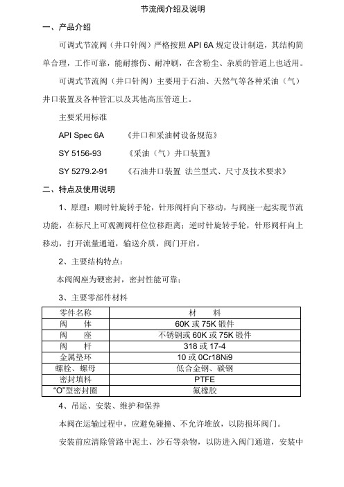
可调式节流阀(井口针阀)严格按照API 6A规定设计制造,其结构简单合理,工作可靠,能耐擦伤、耐冲刷,在含粉尘、杂质的管道上也适用。
可调式节流阀(井口针阀)主要用于石油、天然气等各种采油(气)井口装置及各种管汇以及其他高压管道上。
主要采用标准
API Spec 6A 《井口和采油树设备规范》
SY 5156-93 《采油(气)井口装置》
SY 5279.2-91 《石油井口装置法兰型式、尺寸及技术要求》
二、特点及使用说明
1、原理:顺时针旋转手轮,针形阀杆向下移动,与阀座一起实现节流功能,在标尺上可观测阀杆位位移距离;逆时针旋转手轮,针形阀杆向上移动,打开流量通道,输送介质,阀门开启。
2、主要结构特点:
本阀阀座为硬密封,密封性能可靠;
3、主要零部件材料
4、吊运、安装、维护和保养
本阀在运输过程中,应避免碰撞、不允许堆放,以防损坏阀门。
安装前应清除管路中泥土、沙石等杂物,以防进入阀门通道,安装中
禁止重敲击阀门任何部位。
本阀顺时针为关,逆时针为开;应严格按有关安全操作规程进行,严禁随意松动阀盖上任何紧固件,以确保安全。
本阀不应在露天存放,不应近火,存放保管环境应干燥,温度在0°C~30°C之内,严禁杂物灰尘进入通道;定期在转动处、填料压盖、注脂嘴等部位涂防锈油。
可能发生的故障及排除方法:。
节流阀使用说明书

节流阀使用说明书节流阀使用说明书一、产品概述节流阀是一种流量控制元件,通过改变通道面积来控制流体流量。
它广泛应用于液压、气动和流体控制系统中,能够实现精确的流量调节和压力控制。
二、工作原理节流阀是通过减小通道面积来减小流体流量,从而实现对流量的控制。
当流体通过节流阀时,由于通道面积的减小,流体的速度会增加,压力会降低。
节流阀的结构简单,可靠性高,能够实现精确的流量控制。
三、使用场景节流阀广泛应用于液压、气动和流体控制系统中,特别是在需要精确控制流量的场合,例如机械手、机械臂、自动化生产线等。
四、操作方法1、在安装节流阀之前,需要检查管道是否清洁,以免杂质进入节流阀。
2、将节流阀安装在管道上,确保密封良好,以免泄漏。
3、根据需要调节节流阀的开口度,开口度越大,流量越大;开口度越小,流量越小。
4、在使用过程中,需要经常检查节流阀的工作状态,如有异常应及时处理。
五、注意事项1、在调节节流阀时,应注意不要过分调节,以免损坏节流阀。
2、在使用过程中,应注意避免节流阀受到冲击和振动,以免损坏节流阀。
3、在更换节流阀时,应选用与原来型号一致的节流阀,以免影响使用效果。
六、维护保养1、定期清洗节流阀,清除杂质和污垢,以保证其正常工作。
2、对于长期不使用的节流阀,应做好防锈处理,以保证其正常工作。
3、在维护保养过程中,如发现节流阀有损坏或异常,应及时更换或维修。
七、总结本说明书介绍了节流阀的工作原理、使用场景、操作方法、注意事项和维护保养等内容,以便用户能够正确使用和维护节流阀。
在使用过程中,还应注意安全,避免出现意外情况。
如有疑问,请及时联系生产厂家或专业技术人员进行咨询。
机器人使用说明书机器人使用说明书关键词:机器人、使用、说明书尊敬的用户,欢迎您使用我们的机器人产品。
本说明书旨在向您提供机器人的使用指南和相关信息,以帮助您充分了解其功能和使用方法。
我们的机器人是一款智能设备,可以代替人类完成各种任务,具有高精度、高效率的特点。
活塞式调流调压阀说明书以及产品资料介绍

根据 Kv-Value 曲线从“L40”型号的上欧活塞阀 中选择 DN
表3
Kv=906 m³/h
根据上述曲线选择
DN 400
上欧活塞式调流阀出口四种形式之一 E形:截弯取直结构
preferably for regulating purposes
- high pressure difference sufficient back pressure required - cut-off edge and sudden enlargement of crosssectional area to reduce cavitational effects
s的值越小, 气蚀的倾向越严重
例:
H H Hd 2 AT s v2 (H H ) 1 2 2g 15 10 0,23 4,212 (29 15) 19,62 1,75
已知数据 : Q= 1073 m³/h H1= 29,0 mWC H2= 15,0 mWC Dp= 14,0 mWC
Storage A
Storage C
Storage B
Network 2 Network 1 approx. 5 km
Radio modem
Achtung: Vorschriften der einzelnen Länder überprüfen bezüglich der Zulassung von Funk
何谓气蚀
气蚀是指流体在节流作用下,节流器件后 端因压力急剧下降,导致液体发生汽化,而后 又在气泡发生湮灭过程中,对器件微观表面造 成强烈冲击,进而产生噪音、振动、腐蚀的现 象。
蝶阀从全开到全闭,流体速度的变化过程演示
velocity [m/s]
【F'A】电动调节阀说明书
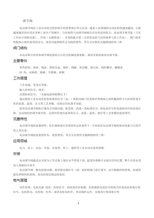
调节阀电动调节阀是工业自动化过程控制中的重要执行单元仪表。
随着工业领域的自动化程度越来越高,正被越来越多的应用在各种工业生产领域中。
与传统的气动调节阀相比具有明显的优点:电动调节阀节能(只在工作时才消耗电能),环保(无碳排放),安装快捷方便(无需复杂的气动管路和气泵工作站)。
阀门按其所配执行组织使用的动力,按其功能和特性分为线性特性,等百分比特性及抛物线特性三种阀门结构由电动执行组织和调节阀连接组合后经过机械连接装配、调试安装构成电动调节阀。
主要零件零件材料:阀体、阀盖、填料压盖、阀杆、阀瓣、密封圈、指示标、阀杆螺母、螺帽套材料:灰铸铁、铸钢、不锈钢、黄铜工作原理工作电源:等电压等级。
输入控制信号:或者。
反馈控制信号:(负载电阻碍欧姆以下)通过接收工业自动化控制系统的信号(如:)来驱动阀门改变阀芯和阀座之间的截面积大小控制管道介质的流量、温度、压力等工艺参数。
实现自动化调节功能。
新型电动调节阀执行器内含饲服功能,接受统一的或·的标准信号,将电流信号转变成相对应的直线位移,自动地控制调节阀开度,达到对管道内流体的压力、流量、温度、液位等工艺参数的连续调节。
流量特性电动调节阀的流量特性,是在阀两端压差保持恒定的条件下,介质流经电动调节阀的相对流量与它的开度之间关系。
电动调节阀的流量特性有:线性特性,等百分比特性及抛物线特性三种。
应用领域电力、化工、冶金、环保、水处理、轻工、建材等工业自动化系统领域。
安装电动调节阀最适宜安装为工作活塞上端在水平管线下部。
温度传感器可安装在任何位置,整个长度必须浸入到被控介质中。
电动调节阀一般包括驱动器,接受驱动器信号(或)来控制阀门进行调节,也可根据控制需要,组成智能化网络控制系统,优化控制实现远程监控。
电气原理动作原理:电机电源或者,控制信号,阀里面有控制器,控制器把电流信号转换为步进电机的角行程信号,电机转动,由齿轮,杠杆,或者齿轮加杠杆,带动阀杆运作,实现直行程或角行程反馈:电机运行,通过齿轮运转,由三接头的滑动变阻器输出阀门的定位信号,此外还有三根线的限位信号(全开,全闭。
可调式节流阀技术协议52-70)

JLK52-70可调式节流阀技术协议甲方:山东科瑞井控系统制造有限公司乙方:盐城三益石化机械有限公司JLK52-70可调式节流阀技术协议甲方:乙方:甲方向乙方订购JLK52-70手动可调式针形节流阀,经甲、乙双方就有关技术参数、配套范围、技术文件等进行协商,达成如下技术协议。
一、产品规格及执行标准:1、产品规格:2、执行标准:1.1所有零部件的设计、制造、验收、包装等均符合API SPec 6A 20版《井口装置和采油树规范》和《井口装置和采油树设备规范》(SY/T 5127-2008);1.2螺纹扣的加工及验收符合GB/T 9253《石油天然气工业套管、油管和管线管螺纹加工、测量和检验》;1.3ASTM D1414 《O-型橡胶圈标准试验方法》;1.4螺栓的制造验收符合A193《高温用合金钢和不锈钢螺栓材料》,螺母的制造验收符合A194《高温高压用碳钢和合金钢螺栓用螺母》;1.5无损检测应符合JB/T 4730《压力容器无损检测》的要求;1.6承压零件应符合NACE MR0175《油田设备用抗硫化物应力开裂的金属材料》的要求;1.7产品的设计、制造、验收应符合API Q1第7版《质量管理纲要》和ISO9001:2000《设计、制造、安装和服务的质量管理体系》的要求。
二、技术参数:2.1 JLK52-70可调式节流阀技术参数描述:a.公称压力:10000Psi (70MPa)b.主通径:2 1/16″(52mm)c.产品性能级别:PR2d.产品规范级别:PSL2e.产品材料级别:DD级f.额定温度级别:U(-18℃~+121℃)g.工作介质:天然气、泥浆、原油h.连接形式:法兰端面连接2.2 材料要求:a、节流阀本体、盖、端部和出口法兰连接部位材料采用30CrMo合金钢锻件制造而成,阀杆采用12Cr13,表面软氮化,密封锥面堆焊钴基合金,厚1.0-1.2mm;b、非金属密封件采用聚四氟乙烯和丁晴橡胶材料;c、节流阀本体、盖、端部和出口法兰材料化学成分符合API SPEC 6A中的规定,其中S、P含量不超过0.025%,调质处理后机械性能为75K:HB198-234,σb≥655MPa,σs≥517 MPa,δ≥17%,ψ≥35%,AKV≥20.3J;d、螺栓采用42CrMo,材料化学成分符合API SPEC 6A中的规定,其中S、P含量不超过0.025%,经调质处理后机械性能达到:σb≥865MPa,σs≥725 MPa,δ≥15%,ψ≥50%。
节流阀使用说明书
一、前言
低温节流截止阀广泛用于气体、液体管道系统中,起节流降压截止作用,具有结构简单、调节方便、密封可靠、适用性广。
二、阀门主要性能规范
1、公称通径:10~200mm
2、公称压力:1.6~4.0MPa
3、出口调节压力:根据设计调节系统设定。
(0.01~0.6MPa)
4、使用温度:-200~+40℃低温调节阀
5、适用介质:氧、氮、氩、空气、二氧化碳、天然气、乙炔
(氧气、乙炔、天然气均需作脱脂处理)
6、连接形式:焊接
7、阀体材料:不锈钢、铜、碳钢
三、工作原理及结构说明
该阀与管路连接为焊接式,采用手动旋转手轮,阀杆在梯形螺纹的带动下,阀杆带动阀顶同阀体的密封座组成密封副,对介质起截止作用,由锥形阀顶和密封座改变通路截面积来调节流量和压力.
四、使用维护
1、阀门应存放在干燥室内、零件轻放,产品不得有任何磕、
碰、伤等缺陷。
2、阀门安装时阀门介质流向应一致。
3、管道安装好后,应将管内焊渣、油污、残存物吹除干净,
有特别要求的,在安装前作特别处理后再装上,用于氧气、乙烯、天然气介质的须作脱脂处理。
(用于乙炔介质时禁止用铜材质)
2002年8月。
贝利摩液氨节流阀B265说明书
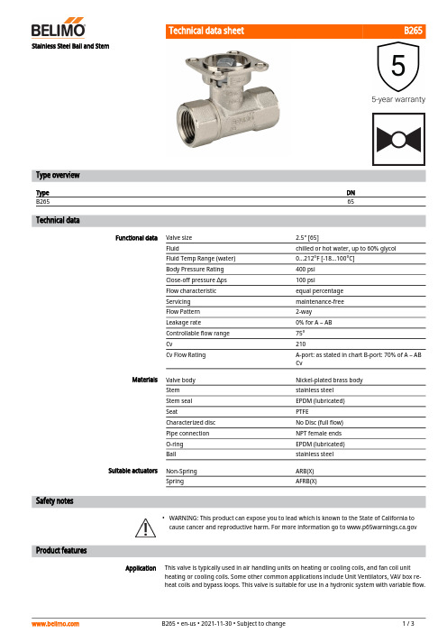
B265•ApplicationStainless Steel Ball and StemType overviewType DN B26565Technical dataFunctional dataValve size 2.5" [65]Fluidchilled or hot water, up to 60% glycol Fluid Temp Range (water)0...212°F [-18...100°C]Body Pressure Rating 400 psi Close-off pressure ∆ps 100 psiFlow characteristic equal percentage Servicing maintenance-free Flow Pattern 2-way Leakage rate0% for A – AB Controllable flow range 75°Cv210Cv Flow RatingA-port: as stated in chart B-port: 70% of A – AB CvMaterialsValve body Nickel-plated brass body Stem stainless steel Stem seal EPDM (lubricated)SeatPTFECharacterized disc No Disc (full flow)Pipe connection NPT female ends O-ring EPDM (lubricated)Ballstainless steel Suitable actuators Non-Spring ARB(X)SpringAFRB(X)Safety notesWARNING: This product can expose you to lead which is known to the State of California to cause cancer and reproductive harm. For more information go to Product featuresThis valve is typically used in air handling units on heating or cooling coils, and fan coil unit heating or cooling coils. Some other common applications include Unit Ventilators, VAV box re-heat coils and bypass loops. This valve is suitable for use in a hydronic system with variable flow.B265Mode of operationFlow/Mounting detailsTwo-way valves should be installed with thedisc upstream.Product featuresLocal Control SY2~12, 110vac ModDimensionsType DN B26565ARB, ARXAB C D E F H110.1" [257]5.6" [141]8.0" [203]6.0" [152]2.8" [71]2.8" [71]1.9" [48]AFRB, AFRXAB C D E F 11.5" [293]5.6" [141]8.6" [219]6.6" [168]2.0" [51]2.0" [51]ARQB, ARQXAB C D E F H1H29.9" [251]4.2" [107]8.1" [206]6.1" [155]2.3" [58]2.3" [58]0.8" [20]0.6" [15]B265AFRB N4, AFRX N4A B C D E F13.0" [330] 5.6" [141]10.3" [262]9.3" [235] 3.4" [86] 3.4" [86]ARB N4, ARX N4, NRB N4, NRX N4A B D E F11.4" [289] 5.6" [141]8.0" [203] 3.1" [80] 3.1" [80]AFRX24 N4FootnotesNEMA 4, On/Off, Spring Return, 24 VTechnical dataElectrical dataNominal voltageAC/DC 24 V Nominal voltage frequency 50/60 Hz Power consumption in operation 5 W Power consumption in rest position 2.5 WTransformer sizing 7.5 VA (class 2 power source)Electrical Connection 18 GA appliance cable, 3 ft [1 m], with 1/2" conduit connectorOverload Protectionelectronic throughout 0...95° rotation Functional dataDirection of motion motor selectable by ccw/cw mounting Direction of motion fail-safe reversible with cw/ccw mounting Manual override 5 mm hex crank (3/16" Allen), supplied Angle of rotation 90°Running Time (Motor)75 s / 90°Running time fail-safe <20 s Noise level, motor 45 dB(A)Noise level, fail-safe 62 dB(A)Position indicationMechanical Safety dataDegree of protection IEC/EN IP66Degree of protection NEMA/UL NEMA 4XEnclosure UL Enclosure Type 4XAgency ListingcULus acc. to UL60730-1A/-2-14, CAN/CSA E60730-1:02, CE acc. to 2014/30/EU and 2014/35/EU Quality Standard ISO 9001Ambient temperature -22...122°F [-30...50°C]Ambient temperature note -40...50°C for actuator with integrated heating Storage temperature -40...176°F [-40...80°C]Ambient humidity Max. 100% RH Servicingmaintenance-freeMaterialsHousing material Die cast aluminium and plastic casing†Rated Impulse Voltage 800V, Type of action 1.AA, Control Pollution Degree 3Electrical installationINSTALLATION NOTESActuators with appliance cables are numbered.Provide overload protection and disconnect as required.AFRX24 N4Actuators may also be powered by DC 24 V.Actuators may be powered in parallel. Power consumption must be observed.Parallel wiring required for piggy-back applications.Meets cULus requirements without the need of an electrical ground connection.Warning! Live electrical components!During installation, testing, servicing and troubleshooting of this product, it may be necessaryto work with live electrical components. Have a qualified licensed electrician or other individualwho has been properly trained in handling live electrical components perform these tasks.Failure to follow all electrical safety precautions when exposed to live electrical componentscould result in death or serious injury.Wiring diagramsOn/OffDimensions。
Fleck 7000系列高流量控制阀说明书
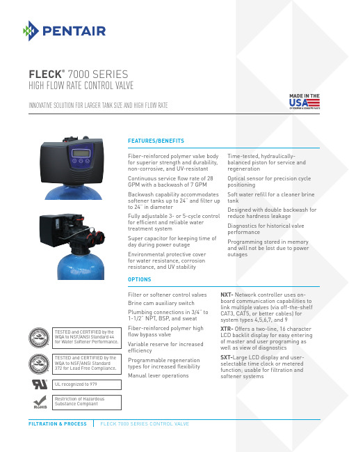
FILTRATION & PROCESSFILTRATION & PROCESS5730 NORTH GLEN PARK ROAD, MILWAUKEE, WI 53209P: 262.238.4400 | | CUSTOMER CARE: 800.279.9404 | tech-support @All Pentair trademarks and logos are owned by Pentair, Inc. or its affiliates. All other registered and unregistered trademarks and logos are the property of their respective owners. Because we are continuously improving our products and services. Pentair reserves the right to change specifications without prior notice. Pentair is an equal opportunity employer.42802 REV F JL14 © 2013 Pentair Residential Filtration, LLC All Rights Reserved.VALVE SPECIFICATIONS Valve Material Fiber-reinforced polymer Inlet/Outlet3/4", 1", 1-1/4”, or 1-1/2" NPT/BSP/Sweat CyclesUp to 6FLOW RATES (50 PSI INLET) – VALVE ALONEContinuous15 psi drop Standard Piston: 28 GPM (6.4 m 3/h) High Flow Piston: 36 GPM (8.2 m 3/h) Filter Piston: 37 GPM (8.4 m 3/h) Peak 25 psi drop Standard Piston: 36 GPM (8.2 m 3/h) High Flow Piston: 46 GPM (10.4 m 3/h) Filter Piston: 47 GPM (10.7 m 3/h) Cvflow at 1 psi drop Standard Piston: 7.1 High Flow Piston: 9.2 Filter Piston: 9.5 Max. Backwash 25 psi drop Standard Piston: 7 GPM (1.6 m 3/h) High Flow Piston: 16 GPM (3.6 m 3/h) Filter Piston: 31 GPM (7 m 3/h)REGENERATIONDownflow/Upflow Downflow only Adjustable Cycles YesTime AvailableSXT: 0 - 199 min/cycle NXT: 0 - 240 min/cycle XTR:0 - 240 min/cycleMETER INFORMATIONMeter Accuracy1-1/4" Turbine: 2 - 40 GPM +5/-8% (0.45 - 9 m 3/h)Meter Capacity Range SXT: 1 - 999,900 gal (0 - 3,785 m 3) NXT: 1 - 9,900,000 gal (0 - 37,476 m 3) XTR: 1 - 9,900,000 gal (0 - 37,476 m 3)DIMENSIONSDistributor Pilot 1.05" O.D. (26.7 mm)Drain Line3/4" or 1” NPTM Brine Valve 1600: 3/8" or 1/2”Injector System 1610Mounting Base 2.5"– 8 NPSM Height from Top of Tank 9" (228 mm)Riser Tube Diameter3/4" (19 mm)Riser Height1/4" Below top of tankTYPICAL APPLICATIONSWater Softener 8 - 24" diameter Filter8 - 24” diameter based on 10 GPM/ft 2ADDITIONAL INFORMATIONElectrical Rating 24VAC50/60 Hz Max VA 15Estimated Shipping Weight T ime Clock/Metered Valve:11 lbsPressure Hydrostatic: 300 psi (20 bar) W orking: 20 - 125 psi(1.4 - 8.5 bar)TemperatureCold Water Valve:34 - 110°F (1 - 43°C)。
昆克流量调节阀说明书

General DescriptionSeries PCK pressure compensated flow control valves are designed to regulate flow at a selected rate, within 5%, regardless of fluctuations in inlet and outlet pressure.OperationSeries PCK valves are factory-set for a specified flow. The flow can be changed with a different “PCK” Orifice Plug Kit (sold separately).Features• Available with reverse flow check.• Flow precision within ±5% of full flow.Technical InformationSpecificationsSeries PC*KPC*K400S PC*K600S PC*K800S PC*K1200SPC*K620S PC*K820S PC*K1020S PC*K1220S Maximum Operating207 Bar (3000 PSI)Pressure Minimum Pressure6.9 Bar (100 PSI) 6.9 Bar (100 PSI) 6.9 Bar (100 PSI) 10.4 Bar (150 PSI)to Compensate Temperature -40°C to +121°C (-40°F to +250°F) Nitrile (standard)Range of-26°C to +205°C (-15°F to +400°F) FluorocarbonSeal Compound Mounting In-lineMaximum Flow 11 LPM (3 GPM) 23 LPM (6 GPM) 57 LPM (15 GPM) 95 LPM (25 GPM) Minimum Flow 1 LPM (0.3 GPM) 2 LPM (0.6 GPM) 6 LPM (1.5 GPM) 10 LPM (2.5 GPM) Reverse Flow, Maximum thru 19 LPM (5 GPM) 30 LPM (8 GPM) 76 LPM (20 GPM) 132 LPM (35 GPM) CheckPressure Drop, 3 Bar(40 PSI) 3 Bar (40 PSI)PC*K800S: PC*K1200S:P at Maximum 8 Bar (116 PSI) 8 Bar (116 PSI) Reverse Flow PC*K1020S: PC*K1220S: Flow thru Check3 Bar (40 PSI)3 Bar (40 PSI)Port Size PC*K400S: 1/4 NPTF PC*K600S: 3/8 NPTF PC*K800S: 1/2 NPTF PC*K1200S: 3/4 NPTF (in.) PC*K620S: PC*K820S:PC*K1020S: PC*K1220S:9/16-18 UNF (SAE 6) 3/4-16 UNF (SAE 8) 7/8-14 UNF (SAE 10) 1-1/16-12 UN (SAE 12)* For optional reverse-flow check, insert “C” in model number at asterisk (*).This product can expose you to chemicals including Lead, Nickel (Metallic), or 1,3-Butadiene which are known to the State of California to go to .Ordering InformationCode Description Omit Without C CheckAvailable Flow Settings GPM (LPM)PCK 400/620PCK 600/820 PCK 800/1020 PCK 1200/1220GPM (LPM)GPM (LPM)GPM (LPM)GPM (LPM)0.25 (0.9) 0.50 (1.9)2.00 (7.57) 4.00 (15.14) 0.50 (1.9) 1.00 (3.8) 3.00 (11.36) 6.00 (22.71) 0.75 (2.8) 1.50 (5.7)4.00 (15.14) 8.00 (30.28) 1.00 (3.8) 2.00 (7.6) 5.00 (18.93) 10.00 (37.85) 1.25 (4.7) 2.50 (9.5)6.00 (22.71) 12.00 (45.42) 1.50 (5.7) 3.00 (11.4)7.00 (26.50) 14.00 (52.99) 1.75 (6.6) 3.50 (13.2)8.00 (30.28) 16.00 (60.56) 2.00 (7.6) 4.00 (15.1)9.00 (34.07) 18.00 (68.13) 2.25 (8.5) 4.50 (17.0) 10.00 (37.85) 20.00 (75.70) 2.50 (9.5) 5.00 (18.9) 11.00 (41.64) 22.00 (83.27) 2.75 (10.4) 5.50 (20.8) 12.00 (45.42) 24.00 (90.84)3.00 (11.4) 6.00 (22.7)13.00 (49.21) 14.00 (52.99) 15.00 (56.78)Code NPTF SAE 4 400 620 6 600 820 8 800 1020 12 1200 1220“PK” Orifice Plug KitsCode Description N Nitrile (Standard) V FluorocarbonDesign Series NOTE: Not required when ordering.Plug KitValve SizeFlow*SealsPKDesign Series NOTE: Not required when ordering.Reverse CheckFixed FlowPort SizeMaterialSeal CompoundKSFlow *Pressure Compensated Flow ControlPCCode Description S SteelCode DescriptionOmit Nitrile (Standard) V FluorocarbonAvailable Flow Settings GPM (LPM)PCK 400/620 PCK 600/820 PCK 800/1020 PCK 1200/1220GPM (LPM)GPM (LPM)GPM (LPM)GPM (LPM)0.25 (0.9) 0.50 (1.9)2.00 (7.57) 4.00 (15.14) 0.50 (1.9) 1.00 (3.8) 3.00 (11.36) 6.00 (22.71) 0.75 (2.8) 1.50 (5.7)4.00 (15.14) 8.00 (30.28) 1.00 (3.8) 2.00 (7.6) 5.00 (18.93) 10.00 (37.85) 1.25 (4.7) 2.50 (9.5)6.00 (22.71) 12.00 (45.42) 1.50 (5.7) 3.00 (11.4)7.00 (26.50) 14.00 (52.99) 1.75 (6.6) 3.50 (13.2)8.00 (30.28) 16.00 (60.56) 2.00 (7.6) 4.00 (15.1)9.00 (34.07) 18.00 (68.13) 2.25 (8.5) 4.50 (17.0) 10.00 (37.85) 20.00 (75.70) 2.50 (9.5) 5.00 (18.9) 11.00 (41.64) 22.00 (83.27) 2.75 (10.4) 5.50 (20.8) 12.00 (45.42) 24.00 (90.84)3.00 (11.4) 6.00 (22.7)13.00 (49.21) 14.00 (52.99) 15.00 (56.78)Note: Settings are based on using 100 SSU at +49°C (+120°F).* To order this valve you must indicate appropriate GPM value from table. Example: 9PCCK600S-3.50-VSeries PC*K400 1/4" 600 3/8" 620 #6 SAE 800 1/2" 820 #8 SAE 1020 #10 SAE 1200 3/4"1220 #12 SAECode Size Note: Settings are based on using 100 SSU at +120°F (+49°C).* To order this plug kit you must indicate appropriate GPM value from table. Example: PK6-3.50-NModel Weight Number kg (lbs.)PK4-*N 0.5 (0.1)PK6-*N 0.5 (0.1)PK8-*N 0.5 (0.1)PK12-*N 0.5 (0.1)Technical Information Performance CurvesDimensionsInch equivalents for millimeter dimensions are shown in (**)Model WeightNumber kg (lbs.)A B C D E F GPC*K400/620 0.03 1/4–18 NPTF/9/16–18 UNF 92.2 27.7 31.8 17.5 38.1 6.4 (0.7) (3.63) (1.09) (1.25) (0.69) (1.50) (0.25) PC*K600 1.003/8–18 NPTF105.7 30.2 38.1 19.1 44.5 6.4(2.1) (4.16) (1.19) (1.50) (0.75) (1.75) (0.25) PC*K 820 1.00 3/4–16 UNF112.5 37.3 38.1 19.1 44.5 6.4(2.1)(4.43) (1.47) (1.50) (0.75) (1.75) (0.25PC*K800/1020 1.50 1/2–14 NPTF/7/8–14 UNF 125.5 36.6 44.5 22.4 50.8 6.4(3.3) (4.94) (1.44) (1.75) (0.88) (2.00) (0.25) PC*K1200/1220 1.50 3/4–14 NPTF/1 1/16–12 UNF 149.4 27.7 57.2 28.7 63.5 6.4(3.3) (5.88) (1.09) (2.25) (1.13) (2.50) (0.25)PC*K SeriesControlled Flow vs.Pressure Dropat Maximum Flow Setting 95190572311P r e s s u r e D r o pLPMGPM25501563FlowSeries PC*K。
卡莫奇 型号 GSCU,GMCU,GSCO,GMCO 阀门 流量控制阀 手册说明书
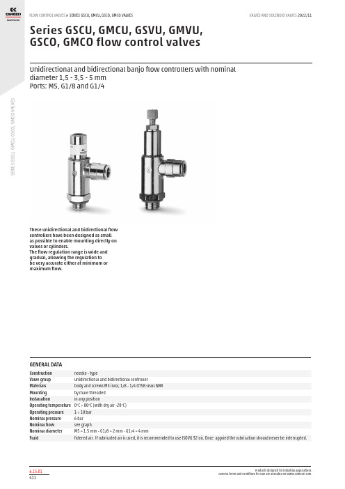
S E R I E S G S C U , G M C U , G S C O , G M C O V A L V E SSeries GSCU, GMCU, GSVU, GMVU, GSCO, GMCO flow control valvesUnidirectional and bidirectional banjo flow controllers with nominal diameter 1,5 - 3,5 - 5 mm Ports: M5, G1/8 and G1/4These unidirectional and bidirectional flow controllers have been designed as small as possible to enable mounting directly on valves or cylinders.The flow regulation range is wide and gradual, allowing the regulation to be very accurate either at minimum or maximum flow.GENERAL DATAConstruction needle - typeValve group unidirectional and bidirectional controller Materials body and screws M5 inox; 1/8 - 1/4 OT58 seals NBR Mounting by male threaded Installation in any position Operating temperature 0°C ÷ 80°C (with dry air -20°C)Operating pressure 1 ÷ 10 bar Nominal pressure 6 bar Nominal flow see graphNominal diameter M5 = 1.5 mm - G1/8 = 2 mm - G1/4 = 4 mmFluidfiltered air. If lubricated air is used, it is recommended to use ISOVG 32 oil. Once applied the lubrication should never be interrupted.S E R I E S G S C U , G M C U , G S C O , G M C OV A L V E SCODING EXAMPLETo ensure the right choice of unidirectional flow controller, proceed as follows: calculate the quantity of air in Nl/min (see cylinder Table); determine the stroke time of the cylinder; refer to graph to see which controller is the right type.S E R I E S G S C U , G M C U , G S C O , G M C O V A L V E STo ensure the right choice of unidirectional flow controller, proceed as follows: calculate the quantity of air in Nl/min (see cylinder Table); determine the stroke time of the cylinder; refer to graph to see which controller is the right type.In the case of bidirectional regulators, refer to the graph and check whether the flow control range is suitable for the work required.M5Flow Qn (Nl/min.) from 2 → 1 with controller OPEN: 70 Flow Qn (Nl/min.) from 2 → 1 with controller CLOSED: 33N° = number of screw turnsNB: Qn is determined with a supply pressure of 6 bar and with ΔP = 1 bar at the outlet.UNIDIRECTIONAL AND BIDIRECTIONAL FLOW CONTROL REGULATORSG1/8Flow Qn (Nl/min.) from 2 → 1 with controller OPEN: 440 Flow Qn (Nl/min.) from 2 → 1 with controller CLOSED: 170N° = number of screw turnsNB: Qn is determined with a supply pressure of 6 bar and with ΔP = 1 bar at the outlet.G1/4Flow Qn (Nl/min.) from 2 → 1 with controller OPEN: 790 Flow Qn (Nl/min.) from 2 → 1 with controller CLOSED: 460N° = number of screw turnsNB: Qn is determined with a supply pressure of 6 bar and with ΔP = 1 bar at the outlet.UNIDIRECTIONAL AND BIDIRECTIONAL FLOW CONTROL REGULATORSS E R I E S G S C U , G M C U , G S C O , G M C O V A L V E SUnidirectional flow controller for mounting on single-acting or double-acting cylinders. Screwdriver adjustment.Ports: M5, G1/8, G1/4 .Valves Series GMCUUnidirectional flow controller for mounting on single-acting or double-acting cylinders. Knurled screw adjustment.Ports: M5, G1/8, G1/4.Valves Series GSVUUnidirectional flow controller for mounting on valves.Screwdriver adjustment.Ports: M5, G1/8, G1/4.S E R I E S G S C U , G M C U , G S C O , G M C O V A L V ESUnidirectional flow controller for mounting on valve. Adjustment of setting by a manually operated knurled screw.Ports: M5, G1/8, G1/4.Valves Series GSCOBidirectional flow controller. Screwdriver adjustment.Ports: M5, G1/8, G1/4.Valves Series GMCOBidirectional flow controller.Adjustment of setting by a manually operated knurled screw.Ports: M5, G1/8, G1/4.。
JLK65-70Z使用说明书
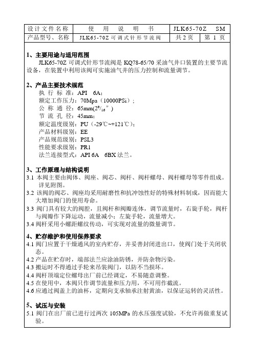
适用温度:-29℃~121℃
材料级别:EE
规范级别:PSL3
性能级别:PR1
本产品经检验符合API SPEC6A规定动作要求,同意出
厂。
检验员:
质管部部长:
总经理:
二OO六年月日
公称通径:65mm(29/16″)
节流孔径:45mm;
额定温度级别:PU(-29℃~+121℃);
产品材料级别:EE
产品规范级别:PSL3
性能要求级别PR1
法兰连接型式:API6A6BX法兰。
3、工作原理与结构说明
3.1本阀主要由阀体、阀座、阀芯、阀杆、阀杆螺母、阀杆螺母等零件组成。详见附图。
3.2该阀的阀芯、阀座均采用耐磨性和抗冲蚀性好的特殊材料制成,因而能大大增加阀门的使用寿命。
设计文件名称
使用说明书
产品型号、名称
JLK65-70Z可调式节流阀
共2页
第2页
5.2阀门在使用前应进行三次密封试验,保证各连接部位不得有渗漏现象。
5.3阀门与管线进行连接安装时,只需在阀门的端部装上BX153垫环;再将配
对法兰用螺栓、螺母联接,并均匀紧固即可。
6、常见故障的排除
6.1当阀座或阀芯冲蚀后,应拆卸该零件并掉面使用或更换。
4.3搬运时不得通过手轮来吊装阀门,以防不当损坏。
4.4阀杆顶端定位螺母出厂前已经调定,不易随意调整。
4.5在使用中,本阀只作调节流量和压力用,不可用作截流。
4.6应通过阀盖上的油杯,定期向支承轴承注射黄油,以保证运转的灵活性。
5、试压与安装
5.1阀门在出厂前已进行过两次105MPa的水压强度试验,不允许再做重复试验。
6.2当阀杆填料处出现渗漏时,应拧紧填料压盖或更换填料。
诺鑫飞 pilots节流阀说明书
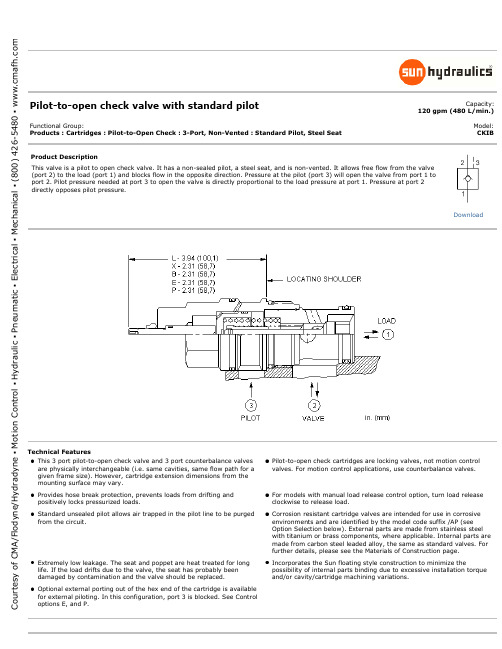
Pilot-to-open check valve with standard pilotCapacity:120 gpm (480 L/min.)Functional Group:Products : Cartridges : Pilot-to-Open Check : 3-Port, Non-Vented : Standard Pilot, Steel SeatModel: CKIBProduct DescriptionThis valve is a pilot to open check valve. It has a non-sealed pilot, a steel seat, and is non-vented. It allows free flow from the valve (port 2) to the load (port 1) and blocks flow in the opposite direction. Pressure at the pilot (port 3) will open the valve from port 1 to port 2. Pilot pressure needed at port 3 to open the valve is directly proportional to the load pressure at port 1. Pressure at port 2 directly opposes pilot pressure.Technical FeaturesPilot-to-open check cartridges are locking valves, not motion control valves. For motion control applications, use counterbalance valves.For models with manual load release control option, turn load release clockwise to release load.Corrosion resistant cartridge valves are intended for use in corrosive environments and are identified by the model code suffix /AP (see Option Selection below). External parts are made from stainless steel with titanium or brass components, where applicable. Internal parts are made from carbon steel leaded alloy, the same as standard valves. For further details, please see the Materials of Construction page.Incorporates the Sun floating style construction to minimize thepossibility of internal parts binding due to excessive installation torque and/or cavity/cartridge machining variations.DownloadC o u r t e s y o f C M A /F l o d y n e /H y d r a d y n e ▪ M o t i o n C o n t r o l ▪ H y d r a u l i c ▪ P n e u m a t i c ▪ E l e c t r i c a l ▪ M e c h a n i c a l ▪ (800) 426-5480 ▪ w w w .c m a f h .c o mCKIB-XCNControlCracking PressureSeal MaterialMaterial/CoatingModifierPreferred OptionsXStandard PilotStandard Options LManual Load ReleasePreferred OptionsC30 psi (2 bar)Standard Options A 4 psi (0,3 bar)B 15 psi (1 bar)D 50 psi (3,5 bar)E 75 psi (5 bar)F100 psi (7 bar)Preferred Options NBuna-NStandard OptionsVVitonPreferred OptionsNo modifier (standard material with no special coating) Special Options/AP Stainless Steel, PassivatedControl: XOur corrosion resistant productline is growing! If you are interested in a corrosionresistant option for this model, please contact Sun.Additional Options (Click Here )ControlCracking PressureSeal MaterialE External 4-SAE Pilot Port, Port 3 Blocked G Slow Acting PilotP External 1/4 NPTF Pilot Port, Port 3 BlockedZ1 psi (0,07 bar)When the modifier is /AP, the control must be XC o u r t e s y o f C M A /F l o d y n e /H y d r a d y n e ▪ M o t i o n C o n t r o l ▪ H y d r a u l i c ▪ P n e u m a t i c ▪ E l e c t r i c a l ▪ M e c h a n i c a l ▪ (800) 426-5480 ▪ w w w .c m a f h .c o mRelated Documents (opens in new window):Explanation of Sun cartridge control options - US units.Copyright © 2002-2011 Sun Hydraulics Corporation. All rights reserved.Terms and Conditions - ISO Certification - Statement of PrivacyC o u r t e s y o f C M A /F l o d y n e /H y d r a d y n e ▪ M o t i o n C o n t r o l ▪ H y d r a u l i c ▪ P n e u m a t i c ▪ E l e c t r i c a l ▪ M e c h a n i c a l ▪ (800) 426-5480 ▪ w w w .c m a f h .c o m。
- 1、下载文档前请自行甄别文档内容的完整性,平台不提供额外的编辑、内容补充、找答案等附加服务。
- 2、"仅部分预览"的文档,不可在线预览部分如存在完整性等问题,可反馈申请退款(可完整预览的文档不适用该条件!)。
- 3、如文档侵犯您的权益,请联系客服反馈,我们会尽快为您处理(人工客服工作时间:9:00-18:30)。
JFK系列可调式节流阀
Adjusted Choke Valve
使用说明书Service Manual
承德江钻石油机械有限责任公司Chengde Kingdream Petroleum Machinery Co., LTD.
2006年yy 10月mm
1. 概述
可调式节流阀主要用于钻井过程中控制井通压力。
通过调整节流阀阀芯提升高度进行节流,实现井控。
该阀按API标准设计制造,具有耐腐蚀性能,使用安全可靠。
2. 主要技术规范
3. 结构说明(见示意图)
3.1阀座、阀杆表面均采用耐冲蚀的特殊材料,使用寿命长。
3.2 具有较大的阀体腔和柱塞式阀芯结构,较之通常的针型结构节流阀, 具有较大的流量, 可较大地消除节流时的震动,减少噪声。
阀体节流出口通道设有耐磨衬套,增加了使用寿命。
3.3 阀体上设有注油嘴,便于现场加润滑脂。
3.4 阀杆顺时针旋转为“关”逆时针旋转为“开”。
3.5该阀为针式结构,即能用于节流,也能截止流量。
4. 维护与保养
4.1 更换阀座及密封件
将阀盖螺母松开,手轮、阀杆、阀盖及密封件便可一并抽出,用专用工具(随阀配带)取出阀座,根据阀座及密封圈的损程度作相应更换。
该阀结构简单,使用方便,易于维护保养。
4. 易损件
可调式节流阀示意图
1. General
Adjusted choke valve is used during drilling course to control well bore pressure. Adjust the 通过调整节流阀阀芯提升高度进行节流,实现井控。
该阀按API标准设计制造,具有耐腐蚀性能,使用安全可靠。
3. Structure (see figure)
3.1 阀座、stem表面均采用耐冲蚀的特殊材料,使用寿命长。
3.2 具有较大的阀体腔和柱塞式阀芯结构,较之通常的针型结构节流阀, 具有较大的流量, 可较大地消除节流时的震动,减少噪声。
阀体节流出口通道设有耐磨衬套,增加了使用寿命。
3.3 阀体上设有注油嘴,便于现场加润滑脂。
3.4 阀杆顺时针旋转为“关”逆时针旋转为“开”。