【中车四方 精品讲义】4步教你安装MRO系统
MRO膜安装方法

MRO膜安装方法
1、拆开膜壳端盖,用纯水将膜过滤工序所有管道冲洗干净。
2、把MRO膜推进膜壳内,膜与膜之间用连接管相连,并记录膜编号。
MRO膜往膜壳里推时应注意:
(1)从本级膜壳的入水端进,往出水端推。
(2)单膜进膜壳时,不带止回橡胶圈的一端(带有膜编号的一端)先进。
(3)在MRO膜两端定位装置的边缘涂甘油减少阻力。
3、安装膜壳端盖
安装端盖时应注意:
(1)使膜壳端盖均匀受力,慢慢敲入膜壳的安装位置。
感觉到端盖与膜壳紧密接触后(声音会有变化),说明已经到了安装位置,套上弹簧钢圈。
弹簧钢圈应完全进入膜壳的卡槽内。
(2)先安装每个膜壳出水端端盖,出水端端盖带有止推环。
(3)安装固定好出水端端盖后,在入水端用力把MRO膜往出水端推,使MRO膜与止推环紧密接触。
(4)在入水端端盖套上两个四氟调整垫圈后安装端盖。
四氟调整垫圈放在端盖与连接管之间。
4、安装渗透液连接管和四氟堵头。
5、检查所有安装工作都完成后,开启纯水泵,按照停车冲洗膜的操作方法,用纯水对新膜冲洗浸泡。
冲洗两罐纯水后,切换为内循环水运。
水运2小时后,可以进盐水。
6、置换盐水,浓缩液出口密度计显示盐水密度到1100之后,说明纯水已经置换完成,具备开启高压泵条件。
6、盐水进膜后,先保持较低压力(进膜压力1MPa)运行2小时,再逐步提压至正常操作压力(正常操作压力为1.5-1.8MPa)。
山东布莱恩化工技术有限公司
2013-7-19。
MRO-L快速安装指南说明书

These short operating instructions apply for the following devices of INSYS icom:▪MRO-L200▪/manualIt is intended for a quick commissioning by the operator. Refer to the associated manual for further information. This and other associated manuals can be found on our website in the menu Support and Downloads > Documentation. Scan the QR code above or enter the URL into your web browser.Defects liability termsA use other than the intended use, an ignorance of the safety instructions and the documentation, the use of insufficiently qualified personnel as well as unauthorised modifications exclude the liability of the manufacturer for damages resulting from this. The liability of the manufacturer ceases to exist.Intended UseThe product may only be used for the purposes specified in the function overview of the manual. In addition, it may be used for the following purposes:▪Usage and mounting in an industrial cabinet.▪Switching and data transmission functions in machines according to the machine directive 2006/42/EC.▪Usage as data transmission device, e.g. for a PLC.The product may not be used for the following purposes and used or operated under the following conditions:▪Use, control, switching and data transmission in machines or systems in explosive atmospheres.▪Controlling, switching and data transmission of machines, which may involve risks to life and limb due to their functions or when a breakdown occurs.Technical BoundariesMax. line length for antennas, power supplies, serial interfaces, inputs and outputs as well as other signals: 30 mCable cross-section: 0.25 … 1.5 (2.5) mm² (depending on terminal size), flexible lines require end sleevesSupportIf you need further support, please contact your sales partner or INSYS icom support. You can contact our support department via e-mail Technical DataThe product is only intended for the use within the permissible technical limits specified in the data sheets. These limits must be observed. Operating voltage 12 V … 24 V DC (±20%) LTE frequencies (4G) 800, 900, 1800, 2100, 2600 MHz (L-200)700, 850, 1700/2100 (AWS), 1900 MHz(L-210)Power consumption typ. 2.5 W, max. 8 W UMTS/HSPAfrequencies (3G) 900, 1800, 2100 MHz (L-200)850, 1700/2100 (AWS), 1900 MHz (L-210)Level input IN1 HIGH level = 2 ... 24 VLOW level = 0 ... 1 VContact open condition: HIGH GSM/GPRS frequencies(2G)900, 1800 MHz (L-200)850, 900, 1800, 1900 MHz (L-210)Current consumption input IN1 at LOW potential typ. 0.1 mA when connectingto GNDReal-time clock (RTC)buffer timetyp. 2 daysLevel input IN2 HIGH level = 10 ... 24 VLOW level = 0 ... 5 VContact open condition: LOW Temperature range -30 °C … 70 °C(75 °C restricted)Power consumption input IN2 at HIGH potential max. 3 mA at 24 V DC Maximum permissiblehumidity95% non-condensingDigital output (open collector), max. load 24 V (DC), 100 mA IP rating Housing IP40Connectors IP30Max. voltage drop of output in state ON < 1 V (DC) at 100 mA loadB LAN settings of configurations PC (Windows 7)If a DHCP client is active on the PC, proceed with step C. Otherwise, either enable the DHCP client or configure a static IP address.6. Open Network and Sharing Center (e.g. key and search for "sharing")7. Select LAN connection and Properties8. Select Internet Protocol Version 4 (TCP/IP) and PropertiesEnable DHCP client9. Obtain an IP address automaticallyIt is recommended to unplug thenetwork cable briefly and plug itagain upon activation of the DHCPclient.Configure a static IP addressUse the following IP address (example):IP address: 192 . 168 . 1 . 2Subnet mask: 255 . 255 . 255 . 0Standard gateway 192 . 168 . 1 . 1Preferred DNS server: 192 . 168 . 1 . 1Please note the previous values beforechanging the TCP/IP settings to be ableto restore them later.C Web interface access10. Enter IP address of the router in address bar of the browser(default: 192.168.1.1)If a proxy server is enabled in your browser, this must be disabled or the IP address of the router must be added as exception.11. Login with Name (default: insys) and Password (icom)All modified data will only be stored in the opened profile after clicking the Save settings button and become effective upon clicking the Activate profile button.You'll get helpful information about the individual parameters in the web interface using the button (Display help text).DConfiguration as Internet Router12. In Menu Help > Wizards: Select Startup Wizard 13. Select Internet access via Cellular network(refer to inline help for WAN over Ethernet)14. Enter PIN of the SIM card15. Enter User name and Password forauthentication with the provider (must not be empty)16. Enter Access Point Name (APN)These data can be found in the contract documents of your SIM card or can be requested from the provider. The APNs of popular providers can be displayed by clinging on .17. Enter IP address of the local applicationnetwork18. Click on Execute wizardIf the router is to be configured for the icom Connectivity Suite - VPN(https://connectivity.insys-icom.de), select icom Connectivity Suite - VPNunder VPN connection and enter Customer name and Device code. Then, the IP address in the local network will be assigned by the icom Connectivity Suite - VPN.The WAN LED flashes green during connection establishment; as soon as an Internet connection has been established, it is illuminated green and the Signal LED flashes orange .EConfiguration of access dataUser name and password for web interface access of the existing user in the default settings must be changed to prevent a manipulation of the configuration by unauthorised persons.19. Menu Administration > Users: Enter or change User name and Password and selectUser group "Read/Write" 20. Store settings in profile with Save settings and activate profile with .A typo during entering or forgetting the configured access data require a reset to default settings to be able to access the router again.All essential configuration steps are completed with this. Further configuration depends on your specific application. Other frequently required settings are available on the following page.IP address in configuration networkThe IP address of the router in the configuration network does only have to be changed, if the IP address is already used or a different address range is required. Then, the web interface is immediately accessible under the new address.1. Menu Interfaces > IP net 1: Adjust IP address of the router in configuration network2. Store settings in profile with Save settings and activate profile with .3. Adjust IP settings of the PC for further configuration accordingly, if these are not obtained automatically (see step B)4.Menu Services > DHCP Server: Adjust address range to the configuration network, if the DHCP server of the router is usedConfiguration Guides and manuals for integrating your product into your application are available in the menu Support and Downloads /supportFor interesting information about your product refer to our website in the menu Knowledge Base/knowledgeHereby, INSYS Microelectronics GmbH declares that herein described device types are in compliance with Directives 2014/53/EU and 2011/65/EU. The full text of the EC Declaration of Conformity is available under /manual.。
迅达5400AP-MMR-现场安装手册
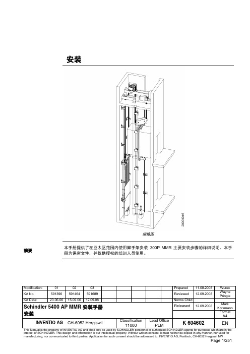
Page 1/251
目录
1 安全建议..................................................................................................................4 1.1 概要 .......................................................................................................................... 4 1.2 使用符号................................................................................................................... 4
3 施工现场准备工作 .................................................................................................10
4 导轨安装................................................................................................................15 4.1 准备工作................................................................................................................. 15 4.2 导轨支架安装.......................................................................................................... 15 4.3 导轨安装................................................................................................................. 21 4.3.1 导轨基座 .................................................................................................. 21 4.3.2 导轨安装 .................................................................................................. 22 4.4 连接板校正 ............................................................................................................. 24
LCR40 RRU快速安装指南PPT课件

制作电源线冷压端子的过程请参见胶片20“制作电源线冷压端子的步 骤”。
TRRU261硬I 件m 安装检N 查a o ge
a TRRU261设备安装检查
序号 1
检查项目 设备的安装位置严格遵循设计图纸,满足安装空间要求,预留维护空间。
2
TRRU261 安装在金属桅杆上时,安装扣件安装牢固,机框固定良好,没有扭曲现象。
安装线缆 硬件检查 上电检查
结束
安装TRRU261-电线杆
此螺钉在拆卸TRRU261 时才需要拧紧
安装TRRU2I 61m -金属N 桅杆a o ge
a 单个TRRU261安装
安装主扣件。
将辅扣构件卡在主扣件的双头螺母之间。
辅扣件的安装位 置
弹片
箭头标识
a.安装主扣件时,请先检查主扣件的弹片是否紧固 好。
b. 为了维护方便,建议主结扣件离地面的高度为 1200mm~1600mm。
c. 当安装主扣件时确保主结构件箭头标识指向上方 向。
辅结构件箭头标识方向
可以在开始安装前将辅扣件的一端卡 在双头螺母上,在安装辅扣件时只要 将另一端也卡在双头螺母上即可。
用活动扳手拧紧螺母,紧固力矩为25N.m~ 30N.m,将结构件固定在金属桅杆上。
制作电源线冷压端子的过程请参见胶片19 “制作电源线冷压端子的步 骤”。
安装TRRU2I 61m 线缆 N a o ge
g TRRU261线缆安装效果图(交流型)
1、电源线压线夹要紧压电源 线屏蔽层,屏蔽层的下沿不 能超过图示位置。 2、电源线另一端的屏蔽层也 需要接地。
射频跳线先用PVC胶带缠绕,再用防水 胶带缠绕,胶带应先由下往上逐层缠绕, 然后从上往下逐层缠绕,最后再从下往 上逐层缠绕。逐层缠绕胶带时,上一层 覆盖下一层约1/2左右 。
北京四方DCS系统硬件使用说明书_800S系列

CSPA-2000 分布式自动化系统(DCS)
Ⅵ CSC-800 分布式控制单元 使用说明书
CSPA-2000 分布式自动化系统(DCS)
CSC-800 分布式控制单元 使用说明书
编
制:嵇涵
标准化审查:李连昌
校 核:徐万方 审 定:奚志江
版 本 号:V2.10 文 件 代 号:0SF.492.016 出 版 日 期:2011 年 8 月
2.3 I/O 模块 ................................................................................................................................. 34 2.3.1 DI 模块.............................................................................................................................. 34 2.3.2 DO 模块 ............................................................................................................................ 43 2.3.3 AI 模块.............................................................................................................................. 45 2.3.4 AO 模块 ............................................................................................................................ 61 2.3.5 PI 模块 .............................................................................................................................. 65
简述轨道交通制造车体总组成小件安装方法、注意事项及用途

简述轨道交通制造车体总组成小件安装方法、注意事项及用途摘要:城市人口不断地增加,地铁是最便利最快捷最通畅的交通工具之一。
所以人们开始重视轨道客车的发展。
彻底的材料分为碳钢,不锈钢,铝合金,碳纤维等。
论述的是铝合金车型,它的优点是耐腐蚀性高工艺性能好轻便。
本文论述了铝合金车体总组成小件各位置的分布及安装步骤讲解。
中车长客第一台铝合金地铁研制于2004年至今也有这16年的历史了,在这14年里铝合金进入了地铁车车发展的行列当中。
铝合金密度低,强度高,接近或超过优质钢,塑性好可加工成各种型材,具有良好的导热性、导电性和抗腐蚀性,工业上广泛使用。
一些发展中国家也大力发展铝合金车体,并具备批量生产铝合金车体的能力。
列车轻量化是提高列车速度的首选条件,减小运行中的阻力,降低能耗,增加载重,因此在各国铁路运输业得到大力度发展。
近年来,由于铁道车辆的高速、轻量化,以及简化施工和维修等要求,促使了大型整体薄板和中空复杂的薄壁型材研制成功。
随着社会和科技的发展,操作技术范围不断扩大,方法丰富更新,但其本质始终不变,而我们这一代技术人工人所需要和掌握的实际经验和岗位操作技能的是不可或缺的重要组成部分。
关键词:城轨车铝合金总组成零部件安装一、总组成之车顶小件安装1.主要分部在车体一位端内外部,主要由吊装件和部分加强筋组装件和车顶上门角补强板、上横梁安装。
部分吊装件主要是控制及尺寸使其下到工序能进行完美尺寸安装,这部分主要注意空间位置和部分垂直度的把控。
还有就是部分加强筋的安装,主要保证他的契合度和尺寸位置,使其达到补强效果,有少部分需要验配切割,保证其工艺要求。
2.上门角补板主要是保证门口圆滑过度,使其后续装配有更好的安装空间和外观,安装方法主要是用样板进行划线、切削、打磨、焊接、修磨后达到工艺要求,主要保证门口圆滑过度,无棱角和凹凸现象等。
门上横梁主要是安装在门口上方,使其增加车体门口处的强度和下道工序安装件的定位之用,首先要保证图纸中的定位准确,一般都是一门口中心为准进行定位,以便于装配进行门口组件安装,其次是门口左右对称,和上面铆接件是否完好,是否需要反变形以保证车体尺寸。
轮胎式集装箱门式起重机模块化制作安装方式
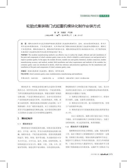
图1 大件铁路运输限制图按照部件进行模块的划分有利于产品的设计、制造、加工和安装的要求,同时考虑运输过程中对模块尺寸、质量的限制。
各模块的尺寸限制为:20 m×3.8 m×3.6 m(长×宽×高)。
按此要求,所有模块都处于公路运输一级大件的范围内,3.8 m的宽度一般占据普通公路2车道,3.6 m的高度在考虑运输车辆的高度以及必要的工装后不超过多数道路5 m的限高要求,有利于行程的规划以及运输工具的选择。
另外,以上尺寸限制也满足铁路运输一级超限货物的要求。
按照以上尺寸要求,常规的场桥产品仅有主梁和小车架外形尺寸超出以上尺寸限制需额外进行分段设计,其余构件仍然遵循原有的结构设计形式,有利于原设计和制造流程的延续。
模块尺寸质量限制说明见表3。
图2 龙门架制作安装流程在传统安装模式下,构件制作完成后进行预拼装预拼装过程中为保证连接处的装配以及构件的整体尺寸往往会对构件进行修割或校正。
总装时,如有必要还会对接口处尺寸再次进行处理。
而模块化场桥各构件采用成品化制作,不允许动火进行修割和校正,拼装也就无法进行。
同样,安装也必须一次到位,不进行调整关的安装精度则需通过构件本身的制作来保证。
模块式构件的制作必须同时满足接口处的装配关系以及安装后结构的整体尺寸要求。
在此,以场桥龙门架,讨论模块连接的常规精度要求。
1)接口处精度如图3所示,出于产品外观的要求,上下法兰边缘图3 模块式龙门架接口处精度2)整体精度要求如图4所示,对于垂直度,如支腿横梁连接后支腿图4 模块式龙门架整体精度各构件的精度要求决定了其特殊的制作加工要求尤其是对于接口部位(如法兰等)的处理。
目前,采取的方法大致有工装模拟拼装状态、整体加工方案、综合以上两种方式等。
①工装模拟拼装状态传统方式中,安装尺寸主要通过拼装过程来保证,而在模块化制作中,必须在结构件制作中即对安装尺寸进行控制,采用工装进行模拟拼装状态,保证安装尺寸成为有效手段。
东方运输工程车安装说明(3篇)
第1篇一、前言本安装说明旨在指导用户正确安装东方运输工程车,确保车辆安全、可靠地投入使用。
请用户仔细阅读本说明,并按照步骤进行操作。
若在安装过程中遇到问题,请联系东方运输工程车售后服务部门。
二、安装工具与材料1. 安装工具:- 扳手- 螺丝刀- 车用千斤顶- 车用工具箱- 平衡机- 水平尺2. 安装材料:- 工程车底盘- 车架- 车厢- 发动机- 变速箱- 驱动桥- 车轮- 车轴- 悬挂系统- 制动系统- 转向系统- 车灯- 水箱- 油箱- 电气系统组件三、安装步骤1. 基础设施准备在开始安装之前,请确保以下基础设施已经准备就绪:- 安装场地平整,无障碍物。
- 水电供应充足。
- 安全防护措施到位。
2. 底盘安装(1)将底盘放置在平整的场地上。
(2)按照底盘说明书安装车架、悬挂系统、制动系统、转向系统等组件。
(3)将车轮、车轴安装到底盘上,确保车轮与车轴的连接牢固。
3. 发动机安装(1)将发动机放置在底盘上。
(2)连接发动机与底盘之间的支架,确保连接牢固。
(3)安装发动机冷却系统、排气系统、燃油系统等。
4. 变速箱安装(1)将变速箱放置在底盘上。
(2)连接变速箱与发动机,确保连接牢固。
(3)安装变速箱冷却系统、油泵等。
5. 驱动桥安装(1)将驱动桥放置在底盘上。
(2)连接驱动桥与变速箱,确保连接牢固。
(3)安装驱动桥油封、制动鼓等。
6. 车厢安装(1)将车厢放置在底盘上。
(2)连接车厢与底盘,确保连接牢固。
(3)安装车厢门、车窗等。
7. 电气系统安装(1)按照电气系统接线图,连接各个电气组件。
(2)安装蓄电池、发电机、起动机等。
(3)检查电气系统是否正常工作。
8. 安全检查(1)检查车辆各个系统是否安装牢固。
(2)检查车辆制动系统、转向系统、悬挂系统等是否正常工作。
(3)检查车辆灯光、仪表等是否正常。
四、注意事项1. 在安装过程中,请务必穿戴好安全防护用品,如安全帽、手套、防护眼镜等。
2. 安装过程中,请勿用力过猛,以免损坏零件。
一卡通定量装车系统操作规程

一卡通定量装车系统操作规程定量装车控制系统采用两级主从分布控制。
由一台用于“集中管理”的PC机(上位机)和安装在装车栈台现场的多台台用于“分散发油控制”的下位机(即定量装车控制仪)组成,下位机与上位机之间通过RS485通讯网络或工业以太网及相应的通讯协议来达到数据采集、装车管理和流程控制的功能。
其中,定量装车控制仪要求IC 卡读卡功能,实现IC装车控制,同时具备本地装车控制模式。
定量控制仪可对装车过程进行程序控制、定量装车控制、防溢联锁控制、防静电接地联锁控制,防人体静电释放联锁控制,可燃气体报警联锁控制,电控钥匙盒联锁控制,防爆挡车器联锁控制。
1、一卡通定量装车系统操作程序:2、一卡通定量装车各模块功能(1)定量发油控制确定装车批控仪的工作参数之后,装车批控仪就会按照指定的程序完成自动发油过程,当发油量达到设定值时,自动停止发油。
(2)刷卡装车功能通过装车站一卡通系统写IC卡,然后在定量装车批控仪上刷卡。
(3)接地保护功能当检测到系统没有安全接地时,接地连锁发出报警停止发油。
(4)掉电保护功能发油过程中出现意外掉电时可保存发油参数,通电后可继续发油。
(5)数据采集功能装车批控仪可采集流量计脉冲信号或标准电流信号,须接入防溢油、车辆静电接地夹、电控钥匙盒、人体静电消除器、可燃气体报警器等开关信号。
(6)阀门和泵的顺序控制功能在装车开始时按预定时间顺序依次打开阀(泵),装车到定量时再按照预定的时间和顺序依次关阀(泵),完成自动装车作业。
(7)现场急停功能装车仪设有急停按钮,若发油时现场发生紧急情况,操作员只需按急停按钮即可立即停止发油。
(8)远程和就地实时监视功能装车仪就地操作时,实时显示发油进程和相关设备的状态,远程监控计算机与装车仪同步实时显示发油进程和相关设备的状态。
(9)通讯联网功能满足以工业以太网(通讯协议为开放的Modbus TCP/IP协议)或RS485网等形式与上位机和其它系统相连。
【精品】迅达5400AP-MMR-现场安装手册
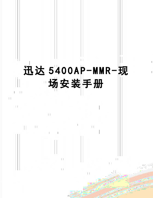
迅达5400A P-M M R-现场安装手册资料内容仅供您学习参考,如有不当之处,请联系改正或者删除安装缩略图摘要本手册提供了在亚太区范围内使用脚手架安装300P MMR 主要安装步骤的详细说明。
本手册为保密文件,并仅供授权的培训人员使用。
目录1 安全建议 (24)1.1 概要 (24)3 施工现场准备工作 (30)30请注意到这步为止不要进行井道样板线设置,尽管下面的尺寸测定可能与土建图一致,但这些尺寸在设置样板线后仍然有可能有变化。
工地安装监督必须获悉所有非正常的结果。
(30) (30)4 导轨安装 (35)4.1 准备工作 (35)在开始安装导轨前必须要安装导轨支架。
挑选并与支架一起安装。
在安装三重导轨支架时必须要小心。
(35)4.2 导轨支架安装 (35)4.3 导轨安装 (41)4.3.1导轨基座 (41)导轨底部基座会用在高楼(HQ>80m)来补偿土建收缩。
导轨基座和底坑组件不能同时使用。
(41) (41)4.3.2导轨安装 (42) (42)4.4 连接板校正 (44)5 Varidor 30AP C2厅门入口安装 (45)5.2 地坎支架 (51)C2 545.4 地坎和护脚板 (56)5.6 C2井道互锁装置 (61)5.7 门解锁装置 (62)5.8 安装门重锤 (63)5.9 防护罩 (65)6 PMS420无齿轮机组安装 (66)6.1 机组支架 (68)82 (83)EN 81-1 (137)Progard LVH (173)轿厢213定位规 (213)亚太应用 (215)亚太应用 (217)NGL 2331 安全建议 (24)1.1 概要 (24)3 施工现场准备工作 (30)30请注意到这步为止不要进行井道样板线设置,尽管下面的尺寸测定可能与土建图一致,但这些尺寸在设置样板线后仍然有可能有变化。
工地安装监督必须获悉所有非正常的结果。
(30) (30)4 导轨安装 (35)4.1 准备工作 (35)在开始安装导轨前必须要安装导轨支架。
培训手册-点检员(MRO使用)
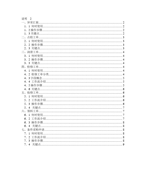
说明2一、异常汇报 (2)1.1 何时使用 (2)1.2 操作步骤 (2)1.3 关键点 (2)二、点检工单 (3)2.1 何时使用 (3)2.2 操作步骤 (3)2.3 关键点 (3)三、润滑工单 (4)3.1 何时使用 (4)3.2 操作步骤 (4)3.3 关键点 (4)四、检修工单 (4)4.1 何时使用 (4)4.2 检修工单分类 (4)4.3字段概念 (5)4.4 工作流介绍 (5)4.5 操作步骤 (5)4.6 关键点 (6)五、抢修工单 (6)5.1 何时使用 (6)5.2 工作流介绍 (6)5.3 操作步骤 (6)5.4 关键点 (7)六、领料工单 (7)6.1 何时使用 (7)6.2 工作流介绍 (7)6.3 操作步骤 (8)6.4 关键点 (8)七、备件采购申请 (8)7.1 何时使用 (8)7.2 工作流介绍 (8)7.3 操作步骤 (8)7.4 关键点 (9)说明点检员在MAXIMO系统中的主要工作是:异常汇报、点检工单、润滑工单、检修工单、抢修工单、领料工单、备件采购申请。
一、异常汇报1.1 何时使用点检员每天上班后,查询前一天运行作业长完成的运行日志(即运行汇报)和生产作业长完成的生产日志(操作汇报)。
使用应用:异常汇报。
1.2 操作步骤1.查看与自己负责的设备有关的前一天的“操作汇报”、“异常汇报”。
2.创建“异常汇报”。
3.发送工作流。
1.3 关键点1.内容录入完毕,必须先保存。
2.来源:选择该异常的信息来源,且存在以下要求。
3.选择故障代码:三级故障,包括:问题、原因、措施。
4.进入工作流后,有三种选择:a.已完成,该记录自动退出工作流。
b.转检修,记录回到你自己的任务箱,等待你制定检修计划。
(后续工作可以参考检修工单部分的内容。
)c.继续观察:该记录回到你自己的任务箱,等待你的继续处理。
可以重新发送,继续选择该异常转检修或者处理完。
二、点检工单2.1 何时使用点检员每天上班后,查询今天需要进行的点检工单,打印工单,进行点检。
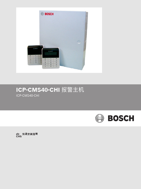
201402 CMS40 简易安装说明
功能
[5][3][#] + [电话编号 1 或 2][#] + [电话号 更改个人报警电话号码 码][#]
[5][3][#] + [电话 1][#]
更改个人报警电话号码 1
[5][3][#][#] + [电话 2][#]
更改个人报警电话号码 2
[5][3][#] + [*][5] + [#]
删除个人报警电话号码 1
功能
[PIN] + [5][3][#] + [电话编号 1 或 2][#] + 更改个人报警电话号码 [电话号码][#]
[PIN] + [5][3][#] + [电话 1][#]
更改个人报警电话号码 1
[PIN] + [5][3][#][#] + [电话 2][#]
更改个人报警电话号码 2
[PIN] + [5][3][#] + [*][5] + [#]
2014.02 | 06 | F.01U.260.762
4 zh-CHS | Table of Contents
6.2.3 6.3 6.3.1 6.3.2 6.4 6.4.1 6.4.2 6.4.3 6.5 6.5.1 6.5.2 6.5.3 6.5.4 6.6 6.6.1 6.6.2 6.6.3 6.6.4 6.6.5 6.6.6 6.6.7 6.6.8 6.6.9 7 8
注解! 不能有相同的 PIN。PIN 也不能和安装员密码相同。
命令
功能
备注
[PIN] + [#]
系统布防
[PIN] + [*]
周界布防
[PIN] + [#]
UNI-RV40 RV Mount Series 1安装说明书

RV Mount SeriesInstallationManualUNI-RV40-MAN 2017 Edition v1.0For m odel: UNI-RV40RV Mount SeriesTable of ContentsIntroduction (1)Customer Support (1)Tools Required (1)Step 1: Pre Assembly (3)Step 2: Final Assembly Attaching clamps to the panel (3)Step 3: Torque Bolts. (3)Step 4: Preparation to mount to a surface (4)Step 5: Attach Panel Supports to any surface (4)Installer R esponsibility (6)Warranty Information (6)IntroductionThe Universal RV Mount is an extremely sturdy mounting solution for installing on top of recreational vehicles, sheds or flat surface. It can also be used as a portable device to place in the sun when your unit is in the shade. With its user adjustable angle settings of 0° to 40° the Universal RV Mount can provide better efficiencies than a permanent flat roof install.Customer SupportTamarack Solar makes every effort to ensure your m ounting kit is easy to install. If you need assistance at any point in your installation or have suggestions on how we can improve your experience, call customer support at1-800-819-7236 or email usTools RequiredTools that support the following size Hex head: Torque values are “dry”, add 15% if using anti-seize lubricant on Stainless hardware (Recommended).1/4” = 84\7 In\Ft LbsComponents List The following parts are for the UNI-RV40 mount model:The left and right panel mounting rails come pre-assembled, the panel mounting clamps come in a bagged kit.Step 1: Pre Assemblyy the panel down with the frame side up.y the pre-assembled panel supports on each end, across the width of the panel with the slotted face onthe panel frame, and centered facing the inside.C.Make note which slots you see the panel frame edge inside of.Step 2: Final Assembly Attaching clamps to the panelA.With the bent ends facing away from the outer ends of the panel supports, loosely assemble the panel clamps inthe slots you have noted, at both ends. Slide the panel clamps up under the panel frame so thebolt makes contact with the edge of the frame.B.Slide the assembly towards the end of the panel so the clamp edge is next to the panel frameStep 3: Torque Bolts.A.Tighten bolts to 7Ft lbs making sure the bolts remain up against the panel frame edge.Step 4: Preparation to mount to a surface.A.Now that the panel support assemblies are attached to the panel, take a measurement between themounting holes from one side to the other.Step 5: Attach Panel Supports to any surfaceA.Attach to surface using 1/4” Ø hardware.B.You can disassemble the middle support and lay the panel over (see illustration next page) to use a ratchet orpower tool to tighten the bolt near the pivot point if needed.C.On curved or irregular surfaces, use a standoff at minimal heights to clear irregularities or curvature.Step 6: Safety PinInstall safety pin when in the flat position for traveling as shown. (See illustration next page)RV Mount SeriesInstallation ManualInstaller ResponsibilityThe installer is solely responsible for:plying with all applicable local or national building codes, including any that may supersede this manual;ii.Ensuring that Tamarack Solar and other products are appropriate for the particular installation and the installation environment;ing only Tamarack Solar parts and installer-supplied parts as specified by Tamarack Solar. Substitution parts may void the warranty;iv.Ensuring safe installation of all electrical aspects of the PV array; andv.Ensuring correct and appropriate design parameters are used in determining the design loading used for the specific installation. Parameters, such as snow loading, wind speed, exposure and topographic factor shouldbe confirmed with the local building official or a licensed professional engineer.Warranty InformationTamarack Solar warrants each Mounting Structure to be free from defects in materials and workmanship for ten (10)years from the date of first purchase (“Warranty Period”), when in stalled properly and used for the purpose for which it is designed, except for the finish, which shall be free from visible peeling, or cracking or chalking under normal atmospheric conditions for a period of three (3) years, from the earlier of 1) the date the installation of the Product is completed, or 2) 30 days after the purchase of the Product by the original Purchaser (“Finish Warranty”). The Finish Warranty does not apply to any foreign residue deposited on the finish.Galvanized coated sheet steel components will show rust on cut edges and is normal and will not affect the structureand function of the mount.All installations in corrosive atmospheric conditions are excluded. The Finish Warranty is VOID if the practices specifiedby AAMA 609 & 610-02 –“Cleaning and Maintenance for Architecturally Finished Aluminum” () are not followed by Purchaser for Tamarack Solar’s aluminum based products.The warranty covers the replacement cost of parts to repair the product to proper working condition. Transportation and incidental costs associated with warranty items are not reimbursable. The warranty does not cover normal wear, or damage resulting from misuse, abuse, improper installation, negligence, or accident, or typographical errors in instruction manuals. The Warranty does not cover any defect that has not been reported in writing to Tamarack Solar within ten (10) days after discovery of such defect. Furthermore, it does not cover units that have been altered, modified or repaired without written authorization from the manufacturer or its authorized representative, or units used in a manner or for a purpose other than that specified by the manufacturer. Tamarack Solar’s entire liability and Purchaser exclusive remedy, whether in contract, tort or otherwise, for any claim related to or arising out of breach of the warranty covering the Mounting Structures shall be correction of defects by repair, replacement, or credit, at Tamarack Solar’s discretion. Refurbished Mounting Structures may be used to repair or replace the Mounting StructuresTamarack Solar shall have no liability for any injuries or damages to persons or property resulting from any cause, whatsoever, or any claims or demands brought against Tamarack Solar by Purchaser, any employee of Purchaser, client of Purchaser, end-user of the Product or other party, even if Tamarack Solar has been advised of the possibility of such claims or demands (collectively, “Third Party Claims”). This limitation applies to all mat erials provided by Tamarack Solar during and after the Warranty Period.。
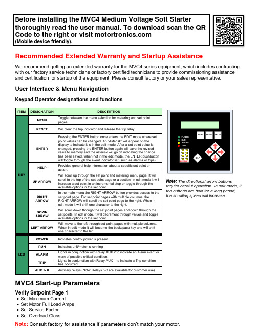
MVC4中压软起动器安装说明书
B efore installing the MVC4 Medium Voltage Soft Starterthoroughly read the user manual. To download scan the QR Code to the right or visit (Mobile device friendly).Recommended Extended Warranty and Startup AssistanceWe recommend getting an extended warranty for the MVC4 series equipment, which includes contracting with our factory service technicians or factory certified technicians to provide commissioning assistance and certification for startup of the equipment. Please consult factory or your sales representative.User Interface & Menu NavigationKeypad Operator designations and functionsNote: The directional arrow buttonsrequire careful operation. In edit mode, if the buttons are held for a long period, the scrolling speed will increase.MVC4 Start-up ParametersVerify Setpoint Page 1• Set Maximum Current • Set Motor Full Load Amps • Set Service Factor • Set Overload ClassNote: Consult factory for assistance if parameters don’t match your motor.ITEMDESIGNATIONDESCRIPTIONKEYMENU Toggle between the menu selection for metering and set point pages.RESETWill clear the trip indicator and release the trip relay.ENTERPressing the ENTER button once enters the EDIT mode where set point values can be changed. An "Asterisk" will appear on the display to indicate it is in the edit mode. After a set point value is changed, pressing the ENTER button again will save the revised value to memory and the asterisk will go off indicating the change has been saved. When not in the edit mode, the ENTER pushbutton will toggle through the event indicator list (such as alarms or trips) HELPProvides general help information about a specific set point or action.UP ARROWWill scroll up through the set point and metering menu page. It will scroll to the top of the set point page or a section. In edit mode it will increase a set point in an incremental step or toggle through the available options in the set point.RIGHT ARROW In the main menu the RIGHT ARROW button provides access to the set point page. For set point pages with multiple columns, the RIGHT ARROW will scroll the set point page to the right. When in edit mode it will shift one character to the right.DOWN ARROW Will scroll down through the set point pages and down through the set points. In edit mode, it will decrement through values and toggle available options in the set point.LEFT ARROW Will move to the left through set point pages with multiple columns. When in edit mode it will become the backspace key and will shift one character to the left.LEDPOWER Indicates control power is present RUNIndicates unit/motor is runningALARM Lights in conjunction with Relay AUX 2 to indicate an Alarm event or warn of possible critical condition.TRIP Lights in conjunction with Relay AUX 1 to indicate a Trip condition has occurred.AUX 1- 8Auxiliary relays (Note: Relays 5-8 are available for customer use)ENTERRESET MENU POWER RUN ALARM TRIP12345678HELPMenu NavigationPassword AccessScreens in Level 1 of the set point menu can be changed without password access because they list basic motor information. Screens in Levels 2 and 3 require passwords because they provide more in-depth protection and control of the unit. The password in Levels 2 and 3 can be changed by the user.Note: Set Points can only be changed when the motor is in Stop/ Ready Mode! The soft starter will not allow a start if it is still in the Edit Mode. When the unit is in the Edit Mode, an asterisk is displayed in the top right corner screen.California Customers:California Proposition 65 WarningWARNING: this product and associated accessories may contain chemicals known to the State of California to cause cancer, birth defects, or other reproductive harm. For more information visit https://MVC4ST-QSL-040623。
装车系统操作规程(3篇)

第1篇一、目的为确保装车作业的安全、高效和有序,特制定本操作规程。
本规程适用于所有装车系统的操作人员。
二、适用范围本规程适用于所有采用机械化装车系统的场所,包括但不限于煤炭、矿石、化工产品、食品等散装或包装货物的装车作业。
三、操作前的准备1. 操作人员需经过专业培训,熟悉装车系统的操作流程和注意事项。
2. 确认装车系统设备运行正常,包括液压泵站、皮带系统、控制系统等。
3. 检查装车站与中控及各相关位置的通讯畅通,确保对讲机通话良好。
4. 检查溜槽、闸板等关键部件是否在安全位置,确保车辆安全通行。
5. 检查装车站缓冲仓料位系统及定量仓称量系统是否工作正常。
四、启动和运行1. 装车站启动前,必须向中控汇报装车系统设备的可操作性,得到中控许可后方可启动流程。
2. 装车系统液压泵启动之前,禁止启动任何闸板。
3. 装车系统装载及卸料必须准确,确认车皮到正确装车位置后方可卸料装车。
4. 装车时操作人员注意力要集中,按装车站正常流程操作,禁止违反操作规程操作。
5. 装车过程中,注意车皮型号及吨位变化,按装车单重量要求装载车皮。
6. 装车即将结束时,提前联系相关操作人员,按量配煤,清空缓冲仓及定量仓内余煤。
五、装车完毕1. 按序停机:a. 确认装车站各项工作都已完成;b. 将溜槽提到最高位;c. 确认各闸板是否在关闭位置;d. 停止液压泵并卸载管路的负荷;e. 关闭计算机。
2. 向中控汇报装车情况。
3. 记录有关数据,包括装车时间、装车量、车皮型号等。
六、安全注意事项1. 操作人员进入装车区域前,必须穿戴好劳保用品,戴好安全帽,禁止穿带铁钉的鞋和化纤衣物等易产生静电的服装。
2. 严禁在装车区域吸烟、使用火种、非防爆通讯器材和电子设备。
3. 作业期间,注意观察风向标,避免火源接近易燃易爆物品。
4. 操作人员应熟练掌握现场消防器材和气防器材的使用方法,熟悉报警方式。
5. 车辆进入装车区时,要求车速不超过15Km/h,在黄线外停稳静止5分钟后,收取《装车通知单》。
【中车四方 精品讲义】4步教你安装MRO系统

登录
安装JAVA插件
安装插 Part 1 件
第一步 安装JAVA插件
1
双击JAVA安装包
2
点击安装
3
安装完成
设置JAVA插件
插件设 Part 2 置
第二步 设置JAVA插件
01
一、路径:控制面板——JAVA插件
02
二、更新——从不检查
第二步 设置JAVA插件
03
三、高级—取消启用JAVA插件
第四步 登录MRO系统
1
输入MRO网址
http:/:80000/
2
填写账号、密码
3
登录系统
我们来总结一下吧
安装
1
设置
2
登录
3
开心测一测喽
Q
A
要登录mro系统,首要步 骤是?
&
安装JAVA插件
提问 & 答案
你会越来越棒的!
中车青岛四方机车车辆股份有限公司
设置浏览器
浏览器 Part 3 设置
第三步 设置浏览器
关闭XSS筛选器 选择关闭 单击确定
路径:Internet选项---安全---自定义级别
第三步 设置浏览器
单击可信站点 选择站点 添加信任点
路径:Internet选项---安全---可信任站点-站点
1、选择可信任站点 2、点击“站点”按钮
3、输入http://*,点击 添加按钮
4步教你安装MRO系统
中车青岛四方机车车辆股份有限公司 检修服务事业部 | 孙冠龙 | 24560 | 2019.6.5
王哥,办公室电脑怎么安装MRO系 统啊;
王哥,我也新买的笔记本电脑,怎么 安装MRO啊 。。。。。。
中国中车供应商操作手册培训课件.doc
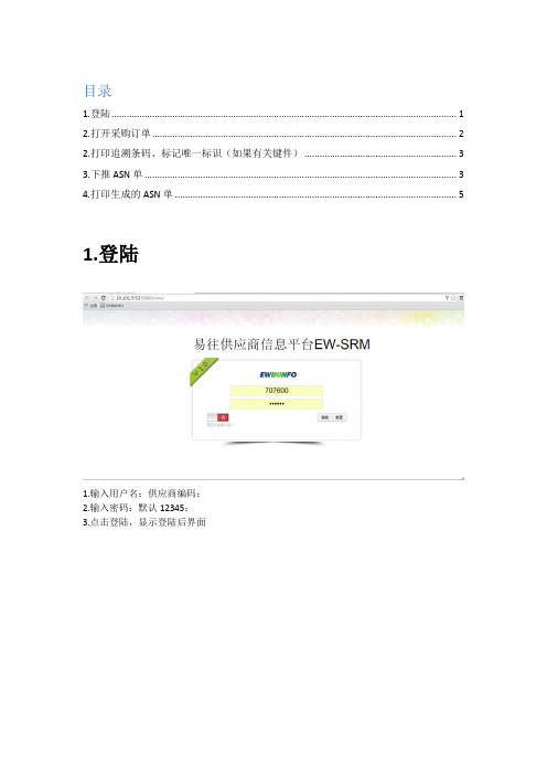
目录
1.登陆 (1)
2.打开采购订单 (2)
2.打印追溯条码、标记唯一标识(如果有关键件) (3)
3.下推ASN单 (3)
4.打印生成的ASN单 (5)
1.登陆
1.输入用户名:供应商编码;
2.输入密码:默认12345;
3.点击登陆,显示登陆后界面
2.打开采购订单
1.点击采购订单,打开采购订单
2.点击超链接,如上图的地方,弹出界面如下:
2.打印追溯条码、标记唯一标识(如果有关键件)
1.点击【关键件追溯】页签,如下图:
2.将2红色框中的唯一标记,记录到物料上。
3.点击【打印】按钮,打印追溯条码,贴至物料上
3.下推ASN单
1.关闭界面,显示至【采购】订单的主界面
1.选中一行明细;
2.勾选中的明细必须得是【未通知收货】或者【部分通知收货】;
3.点击【下推ASN单】
1.可以进行翻页操作;
2.选中需要进行下推的明细(就是采购订单中,需要进行送货的物料明细);3,4,5.维护对应物料本次需要送货的数量、生产日期、预计到货日期;6.点击【生成ASN单】,提示成功信息;7.关闭该界面
4.打印生成的ASN单
1.双击【ASN单管理】,打开ASN单;
2.选中需要打印的ASN单;
3.点击【打印预览】
待一会后,自动跳出选择打印服务,然后点击打印,打印出A4纸的ASN单。
- 1、下载文档前请自行甄别文档内容的完整性,平台不提供额外的编辑、内容补充、找答案等附加服务。
- 2、"仅部分预览"的文档,不可在线预览部分如存在完整性等问题,可反馈申请退款(可完整预览的文档不适用该条件!)。
- 3、如文档侵犯您的权益,请联系客服反馈,我们会尽快为您处理(人工客服工作时间:9:00-18:30)。
第四步 登录MRO系统
1
输入MRO网址
http:/:80000/
2
填写账号、密码
3
登录系统
我们来总结一下吧
安装
1
设置
2
登录
3
开心测一测喽
Q
A
要登录mro系统,首要步 骤是?
&
安装JAVA插件
提问 & 答案
你会越来越棒的!
中车青岛四方机车车辆股份有限公司
4步教你安装MRO系统
中车青岛四方机车车辆股份有限公司 检修服务事业部 | 孙冠龙 | 24560 | 2019.6.5
王哥,办公室电脑怎么安装MRO系 统啊;
王哥,我也新买的笔记本电脑,怎么 安装MRO啊 。。。。。。
简单,我来教你四步搞定!
4步教你如何安装MRO
安装 插件
设置 JAV
A
设置 浏览 器
登录
安装JAVA插件
安装插 Par
2
点击安装
3
安装完成
设置JAVA插件
插件设 Part 2 置
第二步 设置JAVA插件
01
一、路径:控制面板——JAVA插件
02
二、更新——从不检查
第二步 设置JAVA插件
03
三、高级—取消启用JAVA插件
设置浏览器
浏览器 Part 3 设置
第三步 设置浏览器
关闭XSS筛选器 选择关闭 单击确定
路径:Internet选项---安全---自定义级别
第三步 设置浏览器
单击可信站点 选择站点 添加信任点
路径:Internet选项---安全---可信任站点-站点
1、选择可信任站点 2、点击“站点”按钮
3、输入http://*,点击 添加按钮
