派克换向阀样本范文
Parker插装阀样本-流量阀FCsection
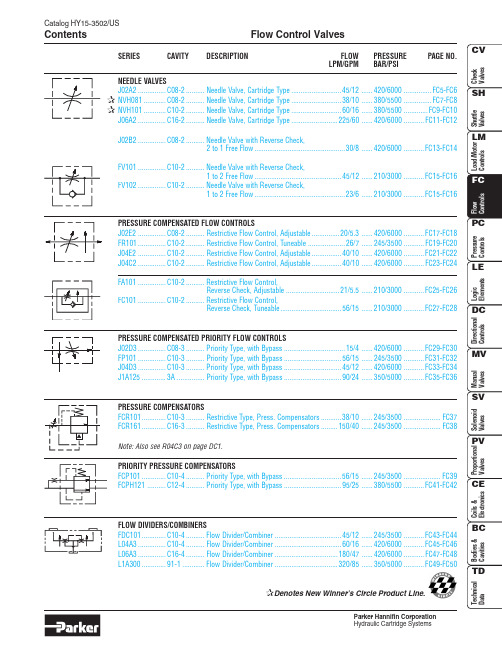
Catalog HY15-3502/USFlow Control Valves ContentsParker Hannifin CorporationFC1Flow Control ValvesCatalog HY15-3502/USTechnical TipsParker Hannifin CorporationINTRODUCTIONThis technical tips section is designed to help familiarize you with the Parker line of Flow Control Valves. In this section we present common options available as well as a brief synopsis of the operation and applications of the various product offered in this section. The intent of this section is to help you in selecting the best products for your application.Adjustment Types: Parker offers four primary types of adjustments for most of the flow control products.Samples of these types are shown below. Please note all options may not be available for all valves. Consult the individual catalog pages for more details.Screw Adjustment - Valve can be adjusted with an allen wrench. Lock nut included to maintain desired setting after adjustment. This is the most common adjustment option available on most Parker products.Knob Adjustment - An aluminum knob is added to the standard screw adjustment. A lock knob is provided to help maintain the desired setting after adjustment. Parker offers knob conversion kits for most flow control valves. For kit numbers consult the individual valve pages.Fixed Style - In most cases, the Fixed Style product is a screwadjustable product with a steel collet threaded over the adjustment.These valves are preset at the factory. Should the valve need to adjusted, the star washer andaluminum plate can be removed from the top of the assembly exposing the adjustment.Tamper Resistant - The tamper resistant option is a screw adjustable valve with a steel cap installed to con-ceal the adjustment. The cap is designed so the internal edges clamp into the groove of the valve adapter. Once the cap is installed, it cannot be removed without damaging the cap and the valve.When a valve is ordered with the tamper resistant option, it will be preset at the factory, and the cap will be included in a separate plastic bag to allow for fine tuning at the customer site. Parker offers tamper re-sistant cap conversion kits for most flow control valves.For kit numbers consult the individual valve pages.Seals: The Winner’s Circle products feature astandard 4301 Polyurethane “D”-Ring. The “D”-Ring eliminates the need for backup rings.The majority of the products are available in Nitrile or Fluorocarbon Seals. You should match the seal compatibility to the temperature and fluid being used in your application.Fine Meter Options: Fine meter needles are offered on some needle valve series. When this option isspecified, the standard needle is replaced by a slotted needle. The slotted needle restricts substantially more flow giving you finer control in the small flow ranges.Obviously, the maximum flow capacity of the needle valve is decreased with the fine meter option.Coarse NeedleFine NeedleCOMMON OPTIONSAs you will see, Parker offers a variety of Flow Control products. As such, some of the options mentioned below may not be available on all valve models. Consult the model coding and dimensions of each valve for specifics.Here are some of the common options available.Catalog HY15-3502/USFlow Control Valves Technical TipsParker Hannifin CorporationFC2FC3Flow Control ValvesCatalog HY15-3502/USTechnical TipsParker Hannifin CorporationCatalog HY15-3502/USFlow Control Valves Technical TipsParker Hannifin CorporationFC4Needle Valve Series J02A2Catalog HY15-3502/USFC5Parker Hannifin Corporation Technical InformationCatalog HY15-3502/USNeedle Valve Series J02A2FC6Parker Hannifin Corporation Technical InformationNeedle Valve Series NVH081Catalog HY15-3502/USFC7Parker Hannifin Corporation Technical InformationHardened, precision ground parts for durability Compact size for reduced space requirements Fine adjustment needle option available for precise Polyurethane “D”-Ring eliminates backup rings and Valve meters flow in either direction, but (2 to 1) is the preferred direction for lowest leakage at shut offCatalog HY15-3502/USNeedle Valve Series NVH081FC8Parker Hannifin Corporation Technical InformationNeedle Valve Series NVH101Catalog HY15-3502/USFC9Parker Hannifin Corporation Technical InformationPerformance CurvesFlow vs. Inlet Pressure Hardened, precision ground parts for durability Compact size for reduced space requirements Fine adjustment needle option available for precise Polyurethane “D”-Ring eliminates backup rings and Valve meters flow in either direction, but (2 to 1) is the preferred direction for lowest leakage at shut offCatalog HY15-3502/USNeedle Valve Series NVH101FC10Parker Hannifin Corporation Hydraulic Cartridge SystemsTechnical InformationNeedle Valve Series J06A2Catalog HY15-3502/USFC11Parker Hannifin Corporation Hydraulic Cartridge SystemsTechnical InformationCatalog HY15-3502/USNeedle Valve Series J06A2FC12Parker Hannifin Corporation Hydraulic Cartridge SystemsTechnical InformationNeedle Valve Series J02B2Catalog HY15-3502/USFC13Parker Hannifin Corporation Hydraulic Cartridge SystemsTechnical InformationCatalog HY15-3502/USNeedle Valve Series J02B2FC14Parker Hannifin Corporation Hydraulic Cartridge SystemsTechnical InformationNeedle ValveSeries FV101 and FV102Catalog HY15-3502/USFC15Parker Hannifin Corporation Hydraulic Cartridge SystemsTechnical InformationFree FlowMetered FlowCatalog HY15-3502/USNeedle ValveSeries FV101 and FV102FC16Parker Hannifin Corporation Hydraulic Cartridge SystemsTechnical InformationP.C. Flow Control Valve Series J02E2Catalog HY15-3502/USFC17Parker Hannifin Corporation Hydraulic Cartridge SystemsTechnical InformationCatalog HY15-3502/USP.C. Flow Control Valve Series J02E2FC18Parker Hannifin Corporation Hydraulic Cartridge SystemsTechnical InformationFC19P.C. Flow Regulator Valve Series FR101Catalog HY15-3502/USParker Hannifin CorporationHydraulic Cartridge SystemsTechnical InformationAdjustable StyleSeries FR101Technical InformationAdjustable StyleSeries J04E2Technical InformationAdjustable StyleSeries J04C2Technical InformationSeries FA101Technical InformationSeries FC101Technical Information(2)Catalog HY15-3502/USP.C. Priority Flow Control Valve Series J02D3FC30Parker Hannifin Corporation Technical InformationFC31P.C. Priority Flow Regulator Valve Series FP101Catalog HY15-3502/USParker Hannifin Corporation Technical InformationFeaturesHardened, precision ground parts for durability Cartridge design(2)FC32Catalog HY15-3502/USP.C. Priority Flow Regulator ValveSeries FP101Parker Hannifin Corporation Technical InformationP.C. Priority Flow Control Valve Series J04D3Catalog HY15-3502/USFC33Parker Hannifin Corporation Technical Information(2)Catalog HY15-3502/USP.C. Priority Flow Control Valve Series J04D3FC34Parker Hannifin Corporation Technical InformationP.C. Priority Flow Control Valve Series J1A125Catalog HY15-3502/USFC35Parker Hannifin Corporation Technical Information(2)Catalog HY15-3502/USP.C. Priority Flow Control Valve Series J1A125FC36Parker Hannifin Corporation Technical InformationFC37Catalog HY15-3502/USParker Hannifin Corporation Restrictive Type Pressure Compensator Valve Series FCR101Technical Information(1)(3)FC38Catalog HY15-3502/USRestrictive Type Pressure Compensator ValveSeries FCR161Parker Hannifin Corporation Technical Information (3)FC39Catalog HY15-3502/USParker Hannifin Corporation Priority Type Pressure Compensator Valve Series FCP101Technical InformationFC40Parker Hannifin CorporationPriority Type Pressure Compensator Valve Series FCPH121Catalog HY15-3502/USFC41Parker Hannifin Corporation Technical InformationCatalog HY15-3502/USPriority Type Pressure Compensator Valve Series FCPH121FC42Parker Hannifin Corporation Technical InformationFlow Divider/Combiner Valve Series FDC101Catalog HY15-3502/USFC43Parker Hannifin Corporation Technical InformationDivider Outlets Combiner Inlets(3)Divider Inlet Combiner OutletCatalog HY15-3502/USFlow Divider/Combiner Valve Series FDC101FC44Parker Hannifin Corporation Technical InformationFlow Divider/Combiner Valve Series L04A3Catalog HY15-3502/USFC45Parker Hannifin Corporation Technical InformationDivider Outlets Combiner Inlets (3)Divider InletCatalog HY15-3502/USFlow Divider/Combiner Valve Series L04A3FC46Parker Hannifin Corporation Technical InformationFlow Divider/Combiner Valve Series L06A3Catalog HY15-3502/USFC47Parker Hannifin Corporation Technical InformationDivider Outlets Combiner Inlets (3)Divider InletCatalog HY15-3502/USFlow Divider/Combiner Valve Series L06A3FC48Parker Hannifin Corporation Technical InformationFlow Divider/Combiner Valve Series L1A300Catalog HY15-3502/USFC49Parker Hannifin Corporation Technical InformationDivider Outlets Combiner Inlets。
Parker Hannifin 品牌的 D1FC 系列进口调控电子方向控制阀门说明书
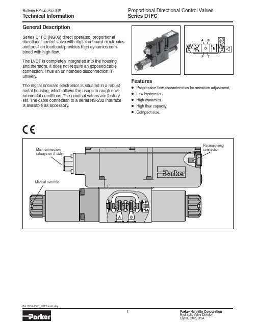
Series D1FCGeneral DescriptionSeries D1FC (NG06) direct operated, proportionaldirectional control valve with digital onboard electronics and position feedback provides high dynamics com-bined with high flow.The LVDT is completely integrated into the housing and therefore, it does not require an exposed cable connection. Thus an unintended disconnection is unlikely.The digital onboard electronics is situated in a robust metal housing, which allows the usage in rough envi-ronmental conditions. The nominal values are factory set. The cable connection to a serial RS-232 interfaceis available as accessory.Features• Progressive flow characteristics for sensitive adjustment.• Low hysteresis.• High dynamics.• High flow capacity.• Compact size.Technical InformationSeries D1FCDirectional Flow Size1Spool CInput SignalDrain Port Y Plugged*9SealDFHigh CDesign Series NOTE: Not required when ordering.Code Description06+PE acc. EN175201-804511+PE acc. EN175201-80476+PE + Enable acc. EN175201-804Code DescriptionN NitrileV FluorocarbonCode SignalFunction B 0...±10V 0...+10V P -> A E 0...±20mA 0...+20mA P -> A S4...20mA12...20mA P -> AElectronic Options Weight:D1FC3.4 kg (7.5 lbs.)Bolt Kit:BK209 (4) 10-24x1.25 SHCS BK375 (4) M5x30Please order connector separately. See Accessories.Parametrizing cable OBE => RS-232 Item no. 40982923* Needs to be removed at tank pressure >35 Bar (507.5 PSI).Spool/ Body Design3Ordering InformationSeries D1FC1)If valves with onboard electronics are used in safety-related parts of control systems, in case the safety function is requested, the valve electronics voltage supply is to be switched off by a suitable switching element with sufficient reliability. 2)Flow rate for different ∆p per control edge:3)Measured with load 210 Bar (3045 PSI) pressure drop; two control edges.Q x = Q Nom. · √∆p x ∆p Nom.SpecificationsSeries D1FC100755025P-B Spool Type E*P-A100-80-60-40-20204060801000F l o w (Q ) % o f N o m i n a l F l o wInput Signal (%)%at p = 5 Bar (72.5 PSI) per metering edgeA-T P-B Spool Type B*B-T100755025%100-80-60-40-20204060801000F l o w (Q ) % o f N o m i n a l F l o wInput Signal (%)P-Aatp = 5 Bar (72.5 PSI) per metering edgeFunctional limits25%, 50%, 75% and 100% command signal (symmetric flow). At asymmetric flow a reduced flow limit has to be considered.All characteristic curves measured with HLP46 at 50 °C.(Electronically set to opening point 10%)Spool type B31/32Spool Type E01/02Performance CurvesSeries D1FCCode 06 + PE acc. EN 175201-804Code 511 + PE acc. EN 175201-804Code 76 + PE acc. EN 175201-804 + EnableWiring ConnectionsSeries D1FC Interface Program Features• Simple editing of all parameters.• Storage and loading of optimized parameter adjustments.• Executable with all Windows ®operating systems fromWindows ®95 upwards.• Communication between PC and electronics via serialinterface RS-232.The valve electronics cannot be connected to a PC with a standard USB cable – this can result in damages of PC and/or valve electronics.Simple to use interface program. Download free of charge /euro_hcd → Services → downloadsProPxD Interface ProgramThe ProPxD software allows quick and easy setting of the digital valve electronics. Individual parameters as well as complete settings can be viewed, changed and saved via the comfortable user interface. Parameter sets saved in the non-volatile memory can be loaded to other valves of the same type or printed out fordocumentation purposes.The parametrizing cable may be ordered under item no. 40982923.Series D1FCInch equivalents for millimeter dimensions are shown in (**)Port Y pluggedRemove and use Y Port if tank pressure > 35 Bar (507 PSI)DimensionsParker Hannifin Corporation Hydraulic Valve Division 520 Ternes AvenueElyria, Ohio 44035 USA Tel: 440 366 5100Bulletin HY14-2561/US,7/15© 2015 Parker Hannifin Corporation. All rights reserved.FAILURE OR IMPROPER SELECTION OR IMPROPER USE OF THE PRODUCTS DESCRIBED HEREIN OR RELA TED ITEMS CAN CAUSE DEA TH, PERSONAL INJURY AND PROPERTY DAMAGE.• This document and other information from Parker-Hannifin Corporation, its subsidiaries and authorized distributors provide product or system options for further investigation by users having technical expertise.• The user, through its own analysis and testing, is solely responsible for making the final selection of the system and components and assuring that all performance, endurance, maintenance, safety and warning requirements of the application are met. The user must analyze all aspects of the application, follow applicable industry standards, and follow the information concerning the product in the current product catalog and in any other materials provided from Parker or its subsidiaries or authorized distributors.• T o the extent that Parker or its subsidiaries or authorized distributors provide component or system options based upon data or specifications provided by the user, the user is responsible for determining that such data and specifications are suitable and sufficient for all applications and reasonably foreseeable uses of the components or systems.WARNING – USER RESPONSIBILITYThe items described in this document are hereby offered for sale by Parker-Hannifin Corporation, its subsidiaries or its authorized distributors. This offer and its acceptance are governed by the provisions stated in the detailed “Offer of Sale” elsewhere in this document or available at /hydraulicvalve.OFFER OF SALEFor safety information, see Safety Guide SG HY14-1000 at /safety or call 1-800-CParker.SAFETY GUIDE。
Parker比例换向阀使用操作技术手册资料

Parker比例换向阀使用操作技术手册资料Parker比例换向阀使用操作技术手册资料PARKER比例换向阀简称比例阀。
普通液压阀只能通过预调的方式对液流的压力、流量进行定值掌控。
但是当设备机构在工作过程中要求对液压系统的压力、流量参数进行调整或连续掌控,例如:要求工作台在工作进给时按慢、快、慢连续变动的速度实现进给,或按肯定精度模拟某个掌控曲线实现旅力掌控。
普通液压阀则实现不了。
这时可以用电液比例阀对液压系统进行掌控。
派克比例换向阀是一种按输入的电信号连续地、按比例地掌控液压系统的液流方向、流量和压力的阀类。
比例换向阀转换装置和液压掌控阀本体两大部分构成。
前者将输入的电信号连续地按比例地转换为机械力和位移输出,后者在接受这种机械力和位移之后、按比例连续地输出压力和流量.Parker比例换向阀有两组密封组件。
每组密封组件(图2)由阀瓣、密封圈、调整块、调整螺钉、夹板和螺栓构成。
阀瓣为碳钢板焊件,设有加强筋,即加添阀瓣强度又起导向作用,保证每组阀瓣间的同轴度。
阀瓣上镶嵌聚氨脂橡胶圈,该料子具有耐油、耐磨损、性能稳定、密封良好和使用寿命长的特点。
在凸轮的作用下,密封圈的球面与阀体密封面相接触产生挤压弹性变形,实现密封效果。
调整块和调整螺钉在两组密封组件不能同步到位时可起调整作用,确保各通道密封性能同步到位。
1夹板 2螺栓 3调整块 4阀瓣 5密封圈 6调整螺钉(3)阀杆与阀体隔板和上阀盖间的轴向密封采用O形圈。
(4)阀体隔板及上阀盖轴孔部位镶有铜套,可减小与O形圈间的摩擦力矩,密封组件开启与关闭敏捷,操作力矩小。
(5)上阀盖设有指示牌及限位螺钉,阀杆上安装指针,明确指示各通道的接通情形,易于操作。
派克Parker比例阀D1FB系列内置OBE放大器版本:这款内置了放大器位于一个坚固的金属外壳中,可以在特别恶劣的环境条件下使用。
标称值在出厂时已经设定。
串行RS232接口的电缆连接可作为附件供应。
派克D1FB系列外置放大器版本:这些参数可以与数字功率放大器PWD00A400结合起来进行保管、更改和复制。
Parker V20方向控制阀门应用解决方案说明书
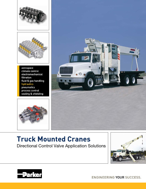
Truck Mounted Cranes Directional Control Valve Application SolutionsParker’s V20 directional control valve is a proven performer in this market. It has very low pressure drops and optimized metering spools designedspecifically for these machines.Other features include:•Integrated unloading valves for anti-tip control•Integrated solenoid to control the functionality of the unloading valves•Solenoid selectable power-beyond for two speed winch operation•Neutral interlock positioner •For radio-remote operation, an integrated section to generate and regulate the pilot signal to the work-section solenoids •Work-section proportionalsolenoids with push pin overridesTruck Mounted CranesParker offers a full line of directional control valves,hydraulic controllers and crane specific solutions for this market.Series V20 ValveDirectional control valve assembly with integrated unloading valves for lift andtele and selectable winch boostParker has developed application specific control solutions for this market, which are intended to improve machine performance and lower the installed cost. Our long standing application knowledge of these machines has enabled Parker to develop features truly valued by the customer and the end-user.Solenoid selectablepower-beyond outletUnloading valve for work ports and two speedwinch operation•Broad offering of port accessories•Pressures up to 3500 PSI •Flows up to 25 GPM •Open-center & Load-senseSeries V20EH ValveThe electrohydraulic package for the V20 includes an on-demand pressure-generating / regulation section. This means that when the spools are in neutral, the open-center pressure drop is low; ~75 PSI @ 20 GPM for a 4-spool assembly.When a spool is selected, a signal is sent to the pressure-generating section to build enough pressure to move the spool.Solenoid Features•Can be used for proportional or on/off control•Available in 12V and 24V •Connector options are Deutsch, Amp Jr and Weatherpak •Pushpin overrides are availableSeries VG20 ValveUsed on winch application with flows from 25-45 GPM. Features:•45 GPM, 3500 PSI •Low pressure drops•Available with unloading valves for anti-tube lock (anti-two block)Outrigger Solution Series MD06 Valve•Direct shift solenoid valve. Does not require any pilot pressure.•Modular design allows for bolt-on options for port accessories.•Available in 2 or 3 position,4-way valves•Flows up to 25 GPM •Pressures up to 3000 PSIOur hydraulic-remotecontrollers have spring packs that optimize the controllability of our directional control valves. They are compact and can fit into the armrest for finger-tip control.Series PCL ControllersSeries V20 Valve with an Integrated ManifoldCustom designed manifold integrated into a V20 to add features and reduce cost for a specific vehicle.•Outstanding relief valve performance•Available spool positioners are manual, pilot and EH.Parker Hydraulics International Sales OfficesParker Hannifin Corporation Hydraulic Valve Division 520 Ternes Avenue Elyria, Ohio 44035 USA Tel: 440-366-5200Fax: 440-366-5253/hydraulicvalve©2010 Parker Hannifin Corporation, all rights reservedBulletin HY14-2407/US,4M, 11/10, RRDNorth AmericaHydraulics Group Headquarters 6035 Parkland BoulevardCleveland, OH 44124-4141 USA Tel:216-896-3000Fax:216-896-4031Parker Hannifin Canada Division 160 Chisholm Drive Milton Ontario, Canada L9T 3G9Tel:905-693-3000Fax:905-876-1958MexicoParker Hannifin de México Industrial Hydraulic Sales Eje Uno Norte No. 100Parque Industrial Toluca 2000Toluca, Edo. de Mexico CP 50100Tel:52 72 2275 4200Fax:52 72 2279 9308Parker Hannifin de México Mobile Hydraulic SalesVia de FFCC a Matamoraos 730Apodaca, NL CP de Mexico 66600Tel:52 81 8156 6000Fax:52 81 8156 6068EuropeHydraulics Group Headquarters La Tuilière 61163 Etoy -Switzerland Tel:41 21 821 8500Fax:41 21 821 8580South AfricaParker Hannifin Africa Pty Ltd P.O. Box 1153ZA-Kempton Park 1620,Republic of South Africa Tel:27 11 961 0700Fax:27 11 392 7213Mobile SalesMobile Sales Organization and Global Sales850 Arthur AvenueElk Grove Village, IL 60007 USA Tel: 847-258-6200Fax: 847-258-6299Industrial SalesCentral Region 1042 Maple Avenue Unit 331Lisle, IL 60532 USA Tel:630-964-0796Great Lakes Region 6035 Parkland BoulevardCleveland, OH 44124-4141 USA Tel:216-896-2740Fax:866-498-7507Gulf Region20002 Standing Cypress Drive Spring, TX 77379 USA Tel:817-473-4431Fax:888-227-9454Southwest Region 700 S. 4th AvenueMansfield, TX 76063 USA Tel:817-473-4431Fax:888-227-9454Mid Atlantic & Southeast Regions1225 Old Alpharetta Rd Suite 290Alpharetta, GA 30005 USA Tel:770-619-9767Fax:770-619-9806Midwest Region 8145 Lewis RoadMinneapolis, MN 55427 USA Tel:763-513-3535Fax:763-544-3418Northeast Region P.O. Box 396Pine Brook, NJ 07058 USA Tel:973-227-2565Fax:973-227-2467Northwest Region6458 North Basin Avenue Portland, OR 97217 USA Tel:503-283-1020Fax:866-611-7308Pacific Region 8460 Kass DriveBuena Park, CA 90621 USA Tel:714-228-2509Fax:714-228-2511Asia PacificParker Hannifin Shanghai Ltd.280 Yunqiao Road,Jin Qiao Export Processing Zone Shanghai 201206, China Tel: 86 21 2899 5000Fax: 86 21 6445 9717Parker Hannifin Hong Kong Ltd.8/F, Kin Yip Plaza 9 Cheung Yee StreetCheung Sha Wan, Hong Kong Tel: 852 2428 8008Fax: 852 2480 4256Parker Hannifin Korea Ltd.9F KAMCO Yangjae Tower949-3 Dogok1-dong, Gangnam-gu Seoul, 135-860, Korea Tel: 82 2 559 0400Fax: 82 2 556 8187Parker Hannifin India Pvt Ltd.Plot No. EL-26, MIDC,TTC Industrial AreaMahape, Navi Mumbai, 400 709, India Tel: 91 22 6513 7081Fax: 91 22 2768 6841Parker Hannifin Australia Parker Hannifin Pty Ltd.9 Carrington RoadCastle Hill, NSW 2154, Australia Tel: 612 9634 7777Fax: 612 9842 5111Latin AmericaParker Hannifin Ind. e Com. Ltda Hydraulics DivisionAv. Frederico Ritter, 110094930-000 Cachoeirinha RS, Brazil Tel: 55 51 3470 6090Fax: 55 51 3470 9281Parker Hannifin Argentina S.A.I.C.Stephenson 27111667-Tortuguitas-Malvinas Argentinas Pcia. de Buenos Aires, Argentina Tel: 54 3327 44 4129Fax: 54 3327 44 4199Pan American Division7400 NW 19th Street, Suite A Miami, FL 33126 USA Tel: 305-470-8800Fax: 305-470-8808。
派克阀门样本Parker Valve
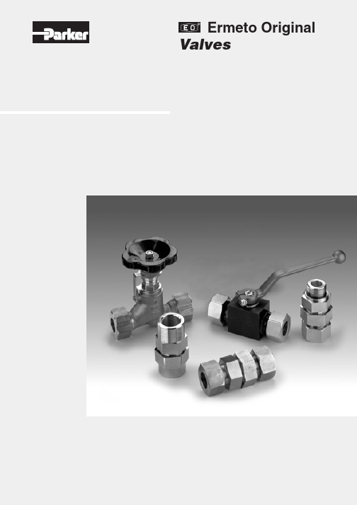
Female NPT thread (SAE 476) / Female NPT thread (SAE 476)
Visual index 3/2-way ball valves
KH 3/2 (S) p. O42
EO 24° cone end / EO 24° cone end / EO 24° cone end
KHBLOCK p. O51
Ball valve with Flange connection DIN EN 1092-1
2/2-way ball valve for block structure
O6
Catalogue 4100-8/UK
Visual index shut off valves and Line Rupture Valves “LRV”
DV p. O52
Valves
LD p. O53
EO 24° cone end / EO 24° cone end
VDHA p. O54
EO 24° cone end / EO 24° cone end
EO tube end / EO tube end
WV p. O55
ELA/ELAE p. O57
KH-A-S-71 p. O48
Ball valve with SAE Flange connection
KH-B4V-S p. O49
Ball valve with SAE Flange adapter connection
KHB5V-S p. O50
Ball valve with SAE Flange connection ISO 6162 (1/2)
派克比例阀英文样本

PID00A-40*
Servo Drives for Positions-/Power Control
Compax 3F
News in Electrohydraulics
Details
Characteristics Ordering Code Technical Data Characteristic Curves Dimensions Characteristics Ordering Code Technical Data Characteristic Curves Dimensions Characteristics Ordering Code Technical Data Characteristic Curves Dimensions Characteristics Ordering Code Technical Data Characteristic Curves Dimensions Characteristics Technical Data, Ordering Code Construction Interface Program Characteristics Technical Data, Ordering Code Construction Interface Program Characteristics Technical Data, Ordering Code Construction Interface Program Characteristics Technical Data, Ordering Code Construction Interface Program Characteristics Technical Data, Ordering Code Construction Interface Program General Ordering Code Technical Data Technology Functions Interfaces / Multi-Axis Control Software Tools Dimensions / Accessories
派克换向阀样本
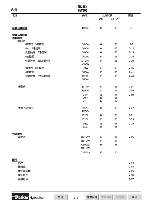
技术参数 概况
结构形式 公称尺寸 接口 安装位置 环境温度 重量:单电磁铁阀 双电磁铁阀 紧固螺栓 滑阀式换向阀 DIN NG6 / CETOP 03 / NFPA D03 DIN 24340 A6 / ISO 4401 / CETOP RP 121-H / NFPA D03 任意,优先考虑水平位置 -25°C...+50°C 1.5 kg 2.1 kg 4 个 DIN 912 M5x30-12.9; 扭矩 8.1 Nm ± 10%; 订货代号 BK 375 液压油依照 DIN 51524 / 51525 标准 -25°C至 + 70°C 2.8 至 400 mm2/s (2.8 至 400 cSt) 350 bar 标准的: 105 bar 代号 H: 210 bar 每个控制边至 10 ml/min 取决于阀芯 80 l/min NAS 1638 7-9级, 达到 β10 > 75 100% ED; 注意: 线圈温度可到150OC IP 65 DIN 40050 标准(在插和装情况下) 吸持 代号 功率 30 W 30 W 8W 30 W 30 W 64 VA / 59 VA 68 VA / 62 VA 直流 32 ms / 40 ms 15.000 次/小时 插头依照 DIN 43650 标准, 可选择 AF/PG11结构的插座, 带引线的接线盒 , 也可选择插入式插头 插头 M12x1 (仅用于 8 W) 电流 2.5 A 1.25 A 0.33A 0.31 A 0.15 A 0.58 A / 0.49 A 0.31 A / 0.26 A 功率 231 VA / 240 VA 231 VA / 240 VA
代号 无 5
说明 标准的阀 不带附件 在接线盒里的指示灯 和接线端子 在接线盒里的插入 式插头外壳 3- 针= 单个电磁铁 5- 针= 双电磁铁 A 端终点位置监控 B 端终点位置监控 选择 5 和6 组合 在一起 A 端初始位置监控
派克液压中文样本

液压注意 – 用户方责任 错误或不当地选择或使用本样本或有关资料阐述的产品,可能会导致人生伤亡及财产损失! 本样本以及其它由派克汉尼汾公司及其子公司、销售公司与授权分销商所提供的资料,仅供用户专业技术人员在对产品和系统的选型进行深入调查考证时参考。
用户应全面分析自身设备的运行工况、适用的工业标准,并仔细查阅现行的样本,以详细地了解产品及系统的相关信息,通过自己的分析和试验,对产品及系统的独立的最终选择负责,确保能满足自身设备的所有性能、耐用性、维修型、安全性以及预警功能等要求。
对于派克或其子公司或授权分销商而言,应负责按用户提供的技术资料和规范,选择和提供适当的元件或系统,而用户则应负责确定这些技术资料和规范对其设备的所有运行工况和能合理预见的使用工况是否充分和准确。
目录目录页次概述 1 订货代号 2 技术参数 4 变量控制器 5 控制选项 “C”, 压力限定(恒压)变量控制器 5 控制选项 “L”, 负载传感及压力限定变量控制器 6 控制选项 “AM”, 带遥控口的标准型先导式压力限定变量控制器 7 控制选项 “AN”, 带ISO 4401 NG06先导阀安装界面的先导式压力限定变量控制器 8 控制选项 “AE”及“AF”, 带电磁比例调节的先导式压力限定变量控制器 9 控制选项 “AMT”, “ALT”及“LOT”, 带最高压力限定的扭矩限定(恒功率)变量控制器 10 P1性能特性 11典型流量特性 11 典型总效率特性 13 典型轴输入功率特性 15 典型噪声特性 18 典型轴承寿命 20 PD性能特性 22典型流量特性 22 典型总效率特性 24 典型轴输入功率特性 26 典型噪声特性 29 典型轴承寿命 31 安装尺寸 33 P1/PD 018 33 P1/PD 028 36 P1/PD 045 40 P1/PD 060 44 P1/PD 075 49 P1/PD 100 54 P1/PD 140 59 变量控制器安装尺寸 65 可提供的扩展的液压产品 75派克汉尼汾备记派克汉尼汾概述简介, 优点派克汉尼汾简介 • 开式回路用轴向柱塞式变量液压泵 • 中压,连续工作压力280 bar • 高驱动转速型,适用于行走机械; 低噪声型,适用于工业应用 • 静音及高效的控制效能 优点 • 总结构尺寸紧凑 • 低噪声• 流量脉动小,进一步降低噪声• 采用弹性密封,不使用密封垫,从而避免外泄漏的产生• 总效率高,功耗小,减小发热• 采用带无泄漏调节装的简单变量控制器 • 符合SAE 及ISO 标准的安装法兰及油口 • 采用圆锥滚柱轴承,使用寿命长 • 全功率后驱动能力• 后部或侧面油口配置可选• 泄油口的配置对水平安装及驱动轴向上垂直安装均适用• 带有最大及最小排量调节选项 • 具有壳体至吸口单向阀选项,可延长轴封寿命 • 使用、维修方便 脉动容腔技术下列图表所示为侧向油口配置P1/PD 18, 28及45泵采用 “脉动容腔” 技术的效果,脉动容腔可降低泵出口处的压力脉动幅值40-60%,这样,无需增加成本来加装噪声缓冲元件,便可大大降低液压系统的整体噪声,P1系列 PD 系列出口压力p / bar平均压力脉动 / b a rP1 045出口压力脉动2600 rpm 无脉动容腔2600 rpm 带脉动容腔订货代号18 ml, 28 ml, 45ml派克汉尼汾P 类型 01 驱动轴 转向R 5密封材料E 油口配置0 壳体-吸口 单向阀 0 排量调节 018 排量 S 安装法兰 及油口 S 轴封 M 应用范围A 设计系列0 通轴驱动选项 C0控制选项0附加控制选项 00油漆 00修改代号系列 P D * 仅适用于045排量, “S”型安装法兰及油口00 标准型, 无修改M2 按要求修改 代号修改代号 * 适用于028及045排量 ** 仅适用于045排量 代号设计系列 A 现行设计系列5 氟碳橡胶 (FPM) 代号密封材料 A 82-2 SAE A M33x2 M27x2 BSPP 1/4”, 3/8” 101-2 SAE B M42x2 M27x2 BSPP 1/4”, 1/2” 101-2SAE B M48x2M33x2Ø38/25DN51/25BSPP 1/4”, 1/2”B ISO M33x2 M27x2 BSPP 1/4”,3/8”ISO M42x2 M27x2 BSPP 1/4”, 1/2” ISO M48x2M33x2Ø38/25DN51/25BSPP 1/4”, 1/2”代号 018排量 028排量 045排量 安装法兰及油口 安装 法兰 螺纹 油口 辅助 油口 安装 法兰 螺纹 油口 辅助 油口 安装法兰螺纹油口法兰 油口辅助 油口 S 82-2 SAE A SAE 16/12 SAE 4/6 101-2 SAE B SAE 20/12 SAE 4/8 101-2SAE B SAE 24/16Ø38/2561系列SAE 4/10M ISO M33x2 M27x2 M12x1.5 M16x1.5 ISO M42x2 M27x2 M12x1.5 M22x1.5 ISO M48x2M33x2Ø38/25DN51/25M12x1.5M22x1.5代号 018驱动轴 028驱动轴 045驱动轴 01 SAE A 11T 花键SAE B-B 15T 花键 SAE B-B 15T 花键02 SAE 19-1平键Ø0.75” SAE B-B 平键Ø1” SAE B-B 平键Ø1” 08— SAE B 13T 花键 SAE B 13T 花键 04 ISO/DIN 平键, Ø20ISO/DIN 平键, Ø25ISO/DIN 平键, Ø25 06 SAE A 9T 花键— — PD 工业液压用 代号 系列P1 行走机械用 代号 排量 018 18 ml/rev (1.10 in 3/rev) 028 28 ml/rev (1.71 in 3/rev) 045 45 ml/rev (2.75 in 3/rev) 代号 类型 P 开式回路用变量柱塞泵 U*通用 代号应用范围 S 工业液压 (PD) M 行走机械 (P1) R 顺时针 (右转)L 逆时针 (左转)代号 转向 代号 轴封 S 单唇轴封 * 并不具有控制功能,仅在运输时予以防护,详情见第7页的控制说明。
派克阀样本手册软件版4

Directional Controls
Logic Elements
LE DC MV SV PV CE BC
Specifications
Rated Flow
80 LPM (21 GPM)
Nominal Flow @ 7 Bar (100 PSI)
Diverter - 40 LPM (10 GPM) Compensator - See Application
DC
Directional Controls
N04G4 .............. C10-4 .......... 3 Way, Vent to Atmosphere, External Pilot ...... 85/22 ...... 420/6000 ................... DC11 N04H4 .............. C10-4 .......... 3 Way, Vent to Atmosphere, External Pilot ...... 85/22 ...... 420/6000 ................... DC12
• LM
Very accurate flow regulation when used with separate
orifice
Load/Motor Controls
• Sealed pilot option available
• Industry common cavity
• FC
Hardened working parts for maximum durability
.............................................. Open Transition .......................................... 400/105 ...... 420/6000 ................... DC14
K220LS 工程机械用方向控制阀 样本MSG17-8537 CN 派克汉尼汾公司说明书

2工程机械用方向控制阀K220LS样本MSG17-8537/CN派克汉尼汾公司移动液压系统欧洲事业部Borås, Sweden样本布局除一般信息和基本技术数据外,该样本还对K220LS 可配置的选配功能做了描述。
我们可据此对K220LS 进行定制配置,以符合您的需求。
多路阀的每个功能区域都有一个副标题,标题后面附有简短的描述。
如果某个功能区有多个不同的位置,则会在副标题的方括号内标注位置编号,例如[P16]溢流阀。
再接下来是一系列带有代号的选项,例如PA1、Y 以及每个代号的简短描述。
或者是一个或多个压力、流量或电压选项。
位置编号也可参见配置代号报告和备件清单。
第8页的一般液压回路图中展示了K220LS 阀的基本功能区、以及代表这些功能区的条目编号。
多路阀订购方式我们开发并推出了配置K220LS 阀的软件。
这个软件也能给您生成阀技术文档,其中会包含详细的阀代号报告、3D 模型、2D 图纸、备件清单和液压原理图。
软件还会创建一个唯一的ID 号,并印在阀产品标签上。
您的阀配置会保存在我们的数据库中,以便查询服务或重新订购时快速确定。
样本信息销售要约请联系您的派克销售代表,获取详细的“销售要约”。
专业建议,以节约时间和成本我们的工程师经验丰富,他们对不同类型的液压系统及其工作原理都有深入的了解。
他们可随时为您提供专业的建议,按您需要的方式将各种机器功能、控制特性和价格要求完美组合在一起。
建议在项目规划阶段尽早咨询派克,为您设计一个完整的液压系统,使您的机器达到理想的操作和控制特性。
派克保留修改产品的权利,恕不另行通知。
本样本中使用了典型的曲线和图表。
即使样本不断修订和更新,也不可避免存在出错的可能。
请联系派克汉尼汾,了解更多有关产品的详细信息。
3工程机械用方向控制阀K220LS样本MSG17-8537/CN派克汉尼汾公司移动液压系统欧洲事业部Borås, Sweden目录目录页码概述....................................................................................................................4技术数据 ............................................................................................................5[P03-P09]概述 ................................................................................................6-7液压原理图 .....................................................................................................8-9进口片 ..............................................................................................................10[P10-P29] 进口片 .......................................................................................10[P12] 内部先导压力供油 ...........................................................................11[P13] 先导压力...........................................................................................11[P14] 先导过滤器.......................................................................................11[P15] 进口片类型.......................................................................................11[P16] 溢流阀...............................................................................................12[P17] 压力设定...........................................................................................12[P20] 负载信号复制阀芯 ...........................................................................13[P24] 回油口T2 ..........................................................................................14[P25] 回油口T1 ..........................................................................................14[P26] 进油口P1 ..........................................................................................14[P28] 用于先导回路的单独回油口............................................................14出口片 ..............................................................................................................15[P30 - P44] 出口片 .....................................................................................15[P31] 油口 ..................................................................................................15[P32] 进油口P2 ..........................................................................................15[P34] 回油口T3 ..........................................................................................15[P40] 先导回路回油口 ...............................................................................15工作片 ..............................................................................................................16[P45-P89] 工作片 .......................................................................................16[P47] 连接油口...........................................................................................16[P50] 阀芯执行器.......................................................................................17PC/PCH 液压阀芯执行器 .....................................................................17ECS2/EC2/ECH2 电液阀芯执行器 .......................................................18[P51] 手柄支架...........................................................................................19[55A, B] 先导节流口...................................................................................20[P56] 插头类型...........................................................................................20[P59] 阀芯执行器变型 ...............................................................................20[P60-P74] 阀芯选择 ...................................................................................21[P60] 阀芯功能...........................................................................................21[P64A, B] 力反馈 ........................................................................................22[P66] 压力补偿器和负载保持单向阀........................................................23[P69] 阀芯名称...........................................................................................24[P71A, B] 工作油口公称流量.....................................................................24[P72] 流量设定...........................................................................................24[P74] 工作片变型.......................................................................................24[P75] 进给减压阀.......................................................................................25[P75A] [P75B] 设定油口A 和B 的进给减压 ................................................25[P76A, B] 溢流阀和防气穴阀.....................................................................26[P85] 侧油口连接.......................................................................................26[P89A, B] 工作油口变型 ............................................................................26[P90-P99] 功能阀块 ...................................................................................27附件 ............................................................................................................27信息..................................................................................................................28[P50] EC2 手动越权 ...................................................................................28尺寸图 ..............................................................................................................29备件..................................................................................................................30[P00]指客户规格中的项目编号。
Parker插装阀样本-逻辑阀LEsection
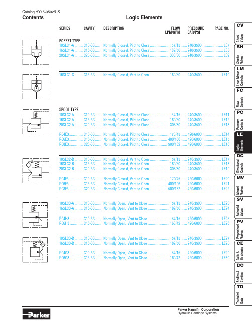
Catalog HY15-3502/USLogic Elements ContentsParker Hannifin CorporationSERIES CAVITY DESCRIPTION FLOW PRESSURE PAGE NO.LPM/GPM BAR/PSIPOPPET TYPE10SLC1-A.........C10-3S........Normally Closed, Pilot to Close.......................57/15......240/3500......................LE7 16SLC1-A.........C16-3S........Normally Closed, Pilot to Close.....................189/50......240/3500......................LE8 20SLC1-A.........C20-3S........Normally Closed, Pilot to Close.....................303/80......240/3500......................LE916SLC1-C.........C16-3S........Normally Closed, Vent to Open.....................189/50......240/3500....................LE10SPOOL TYPE10SLC2-A.........C10-3S........Normally Closed, Pilot to Close.......................57/15......240/3500....................LE11 16SLC2-A.........C16-3S........Normally Closed, Pilot to Close.....................189/50......240/3500....................LE12 20SLC2-A.........C20-3S........Normally Closed, Pilot to Close.....................303/80......240/3500....................LE13R04E3...............C10-3S........Normally Closed, Pilot to Close.....................170/45......420/6000....................LE14 R06E3...............C16-3S........Normally Closed, Pilot to Close..................400/106......420/6000....................LE15 R08E3...............C20-3S........Normally Closed, Pilot to Close..................500/132......420/6000....................LE1610SLC2-B.........C10-3S........Normally Closed, Vent to Open.......................57/15......240/3500....................LE17 16SLC2-B.........C16-3S........Normally Closed, Vent to Open.....................189/50......240/3500....................LE18 20SLC2-B.........C20-3S........Normally Closed, Vent to Open.....................303/80......240/3500....................LE19R04F3...............C10-3S........Normally Closed, Vent to Open.....................170/45......420/6000....................LE20 R06F3...............C16-3S........Normally Closed, Vent to Open..................400/106......420/6000....................LE21 R08F3...............C20-3S........Normally Closed, Vent to Open..................500/132......420/6000....................LE2210SLC3-A.........C10-3S........Normally Open, Vent to Close.........................57/15......240/3500....................LE23 16SLC3-A.........C16-3S........Normally Open, Vent to Close.......................189/50......240/3500....................LE24R04H3..............C10-3S........Normally Open, Vent to Close.........................57/15......420/6000....................LE25 R06H3..............C16-3S........Normally Open, Vent to Close.......................160/42......420/6000....................LE2610SLC3-B.........C10-3S........Normally Open, Vent to Close.........................57/15......240/3500....................LE27 16SLC3-B.........C16-3S........Normally Open, Vent to Close.......................189/50......240/3500....................LE28R04G3..............C10-3S........Normally Open, Vent to Close.........................57/15......420/6000....................LE29 R06G3..............C16-3S........Normally Open, Vent to Close.......................160/42......420/6000....................LE30LE1Logic ElementsCatalog HY15-3502/USTechnical TipsParker Hannifin CorporationCatalog HY15-3502/USLogic Elements Technical TipsParker Hannifin CorporationLE2LE3Logic ElementsCatalog HY15-3502/USTechnical TipsParker Hannifin CorporationCatalog HY15-3502/USLogic Elements Technical TipsParker Hannifin CorporationLE4LE5Logic ElementsCatalog HY15-3502/USTechnical TipsParker Hannifin CorporationDIRECTIONAL CONTROL EXAMPLESTHREE-WAY BRIDGE CIRCUITS Circuit 1, with **SLC1A poppet logic element.Circuit 2, with **SLC2A/R0*E3spool logic element.Circuit 3, with **SLC2A/R0*E3spool logic element.NOTE: Pilot pressure must exceed load pressure in order for valve to close.FOUR-WAY BRIDGE CIRCUITSCircuit 1, with **SLC1A poppet logic elements.Circuit 2, with **SLC2A/R0*E3 spool logic elements.Required Flow PathPilot Pressure Applied To PA PB 123Available From CircuitNONOXXYESNO X X XRequired Flow PathPilot Pressure Applied To PA PB 123Available From CircuitNOYESXXNO YES X XPilot Pressure Applied To P1P2P3P4P5Required Flow PathPilot Pressure Applied To P1P2P3P4P5Required Flow PathPilot Pressure Applied To P1P2P3P4P5Required Flow PathYES YES YES YES YESNO NO NO NO NOYES YESNO NO NONONO YES YES NOYES YES YES YESNOYESNONOYES YESNO YES YES NO YESYES YES NO YES YESNO YES YES YES YESNO YES NO YES YESYESNOYESNOYESYES YES YES NO YESYES NO YES YES YESP APBBACBAP APB CPB BP A ACABC ABCABC ABCPP5TP1P2A P3BP4P2A P1PP5TP4BP3ABP T ABPTABP T ABPTABP T ABP T ABP T ABP T ABP T ABPTABP T ABP T ABP T NOTE: Pilot pressure must exceed load pressure in order for valve to close.Catalog HY15-3502/USLogic Elements Technical TipsParker Hannifin CorporationLE6LE7Catalog HY15-3502/USPoppet Type Logic Valve Series 10SLC1-AParker Hannifin CorporationTechnical Information(3)Poppet Type Logic ValveSeries 16SLC1-A Catalog HY15-3502/USParker Hannifin CorporationTechnical Information(3)(2)LE8LE9Catalog HY15-3502/USPoppet Type Logic Valve Series 20SLC1-AParker Hannifin CorporationTechnical Information(1)(3)(2)Poppet Type Logic ValveSeries 16SLC1-C Catalog HY15-3502/USParker Hannifin CorporationTechnical Information(3)(2)LE10LE11Catalog HY15-3502/USSpool Type Logic Valve Series 10SLC2-AParker Hannifin CorporationTechnical InformationSpool Type Logic ValveSeries 16SLC2-A Catalog HY15-3502/USParker Hannifin CorporationTechnical Information(1)(3) (2)LE12LE13Catalog HY15-3502/USSpool Type Logic Valve Series 20SLC2-AParker Hannifin CorporationTechnical InformationSpool Type Logic ValveSeries R04E3Catalog HY15-3502/USParker Hannifin CorporationTechnical InformationLE14LE15Catalog HY15-3502/USSpool Type Logic Valve Series R06E3Parker Hannifin CorporationTechnical InformationSpool Type Logic ValveSeries R08E3Catalog HY15-3502/USParker Hannifin CorporationTechnical InformationLE16LE17Catalog HY15-3502/USSpool Type Logic Valve Series 10SLC2-BParker Hannifin CorporationTechnical Information(1)(3) (2)LE18Parker Hannifin CorporationLE19Parker Hannifin CorporationSeries R04F3Parker Hannifin CorporationTechnical InformationLE20LE21Parker Hannifin CorporationSeries R08F3Parker Hannifin CorporationTechnical InformationLE22LE23Parker Hannifin CorporationSeries 16SLC3-AParker Hannifin CorporationTechnical Information(2)(3) (1)LE24LE25Parker Hannifin CorporationSeries R06H3Parker Hannifin CorporationTechnical InformationLE26LE27Parker Hannifin CorporationLE28Series 16SLC3-BParker Hannifin CorporationTechnical Information (2)(3)(1)LE29Parker Hannifin CorporationLE30Spool Type Logic Valve Series R06G3Catalog HY15-3502/USParker Hannifin CorporationHydraulic Cartridge SystemsTechnical Information。
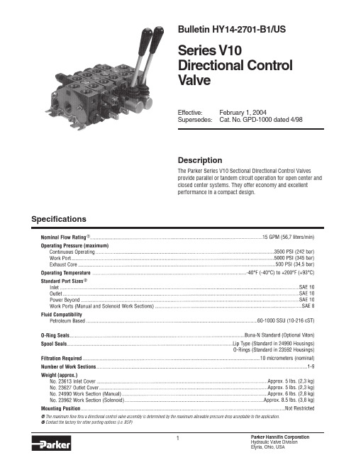
Parker Series V10 方向控制阀门说明书
Bulletin HY14-2701-B1/USSeries V10Directional Control ValveEffective:February 1, 2004Supersedes:Cat. No. GPD-1000 dated 4/98SpecificationsDescriptionThe Parker Series V10 Sectional Directional Control Valves provide parallel or tandem circuit operation for open center and closed center systems. They offer economy and excellent performance in a compact design.➀ The maximum flow thru a directional control valve assembly is determined by the maximum allowable pressure drop acceptable to the application.➁Contact the factory for other porting options (i.e. BSP)PERFORMANCE CURVES •3-Way, 4-Way and 4-Way Float operation •Numerous manual spool positioner options plus remote hydraulic or electric solenoid operation•Work port relief valves and anti-cavitation check valves available•Single handle or dual function mechanical joystick control of manual sections•Enclosed spool ends with handles•Long life - low friction spool seals•Parallel and tandem work sections with individual load (reverse flow) checks•Available for open center, closed center and power-beyond applications•Low flow and high flow spool options available offering flows to 15 GPM (45 LPM)•Continuous system operating pressures to 3500 PSI (Work port pressures to 5000 PSI)•Utilizes many common components such as relief valves, spool positioners and handles with Series V11 and V16FeaturesINLET COVERSOUTLET COVERSWORK SECTIONSWORK SECTIONSWORK SECTIONSSOLENOID OPERATED WORK SECTIONSDIMENSIONS ARE IN INCHES (MILLIMETERS) AND ARE FOR REFERENCE ONLY.DIMENSIONSManually Operated Control Valve AssemblyDIMENSIONSSolenoid Operated Directional Control Valve AssemblyDIMENSIONS ARE IN INCHES (MILLIMETERS) AND ARE FOR REFERENCE ONLY.Parker Hannifin CorporationHydraulic Valve Division 11Bulletin HY14-2701-B1/US,3C, 3/04, PHD Copyright 2004, Parker Hannifin Corporation, All Rights ReservedFAILURE OR IMPROPER SELECTION OR IMPROPER USE OF THE PRODUCTS AND/OR SYSTEMS DESCRIBED HEREIN OR RELATED ITEMS CAN CAUSE DEATH, PERSONAL INJURY AND PROPERTY DAMAGE.This document and other information from Parker Hannifin Corporation, its subsidiaries and authorized distributors provide product and/or system options for further investigation by users having technical expertise. It is important that you analyze all aspects of your application and review the information concerning the product or system in the current product catalog. Due to the variety of operating conditions and applications for these products or systems, the user, through its own analysis and testing, is solely responsible for making the final selection of the products and systems and assuring that all performance, safety and warning requirements of the application are met.The products described herein, including without limitation, product features, specifications, designs, availability and pricing, are subject to change by Parker Hannifin Corporation and its subsidiaries at any time without notice.WARNINGThe items described in this document are hereby offered for sale by Parker Hannifin Corporation, its subsidiaries or its authorized distributors. This offer and its acceptance are governed by the provisions stated in the "Offer of Sale".Offer of Sale Parker Hannifin CorporationHydraulic Valve Division 520 Ternes Avenue Elyria, Ohio, USA 44035Tel:(440) 366-5200Fax:(440) /hydraulicvalve ORDERING CODE。
REXROTH二位四通换向阀产品样本
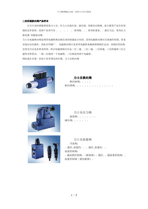
二位四通换向阀产品样本公司专业经销德国原装力士乐,在力士乐液压泵、液压阀、伺服及比例阀、放大板等产品具有很强的竞争优势,优势产品型号有、、、、、系列阀,、、系列柱塞泵,、液压马达,系列压力继电器伺服驱动器。
力士乐电磁换向阀是利用电磁铁推动阀芯来控制液流方向的。
采用电磁换向阀可以使操作轻便,容易实现自动化操作,因此应用极广。
电磁换向阀只是采用电磁铁来操纵滑阀阀芯运动,而阀芯的结构及型式可以是各种各样的,所以电磁滑阀可以是二位二通、二位三通、二位四通、三位四通和三位五通等多种型式。
一般二位阀用一个电磁铁,三位阀需用两个电磁铁。
国际液压市埸一直处于世界领先的位置。
力士乐换向阀力士乐换向阀换向座阀:,,,,换向滑阀:,,,,,,,,,,,,,,,力士乐压力阀溢流阀:,,,,,,,减压阀:,,,,,,力士乐流量阀节流阀:,通径,流量约,。
,通径,流量约,。
流量控制阀:,通流量控制阀,(插装阀),通径。
,通流量控制阀。
,流量控制阀(叠加板阀)。
力士乐比例阀比例换向阀:,,,,,,,。
比例压力阀:比例溢流阀:,,,,,。
比例减压阀:,,,。
比例流量阀:,,,二位四通换向阀是采用控制阀体内的启闭件的开度来调节介质的流量,将介质的压力降低,同时借助阀后压力的作用调节启闭件的开度,使阀后压力保持在一定范围内,并在阀体内或阀后喷入冷却水,将介质的温度降低,这种阀门称为减压减温阀。
该阀的特点,是在进口压力不断变化的情况下,保持出口听压力和温度值在一定的范围内。
减压阀按结构形式可分为薄膜式、弹簧薄膜式、活塞式、杠杆式和波纹管式;按阀座数目可人为单座式和双座式;按阀瓣的位置不同可分为正作用式和反作用式。
先导式减压阀当减压阀的输出压力较高或通径较大时,用调压弹簧直接调压,则弹簧刚度必然过大,流量变化时,输出压力波动较大,阀的结构尺寸也将增大。
为了克服这些缺点,可采用先导式减压阀。
先导式减压阀的工作原理与直动式的基本相同。
二位四通换向阀用在受压设备、容器或管路上,作为超压保护装置。
parker比例阀28页word文档
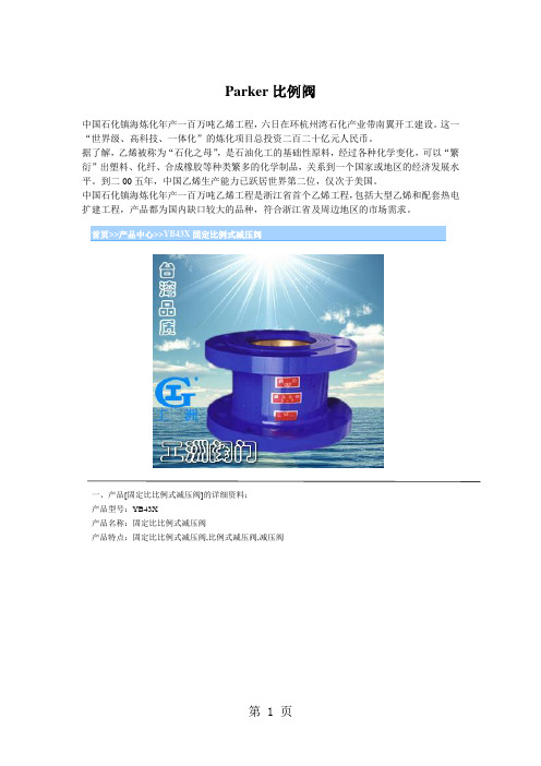
Parker比例阀中国石化镇海炼化年产一百万吨乙烯工程,六日在环杭州湾石化产业带南翼开工建设。
这一“世界级、高科技、一体化”的炼化项目总投资二百二十亿元人民币。
据了解,乙烯被称为“石化之母”,是石油化工的基础性原料,经过各种化学变化,可以“繁衍”出塑料、化纤、合成橡胶等种类繁多的化学制品,关系到一个国家或地区的经济发展水平。
到二00五年,中国乙烯生产能力已跃居世界第二位,仅次于美国。
中国石化镇海炼化年产一百万吨乙烯工程是浙江省首个乙烯工程,包括大型乙烯和配套热电扩建工程,产品都为国内缺口较大的品种,符合浙江省及周边地区的市场需求。
首页>>产品中心>>YB43X固定比例式减压阀一、产品[固定比比例式减压阀]的详细资料:产品型号:YB43X产品名称:固定比比例式减压阀产品特点:固定比比例式减压阀,比例式减压阀,减压阀二、YB43X固定比例式减压阀外形尺寸:公称通径DN lmmlA D325 232 115/12532 246 140/15040 256 150/15550 270 165/17565 306 185/20080 320 210/230100 340 240/265 125 400 275/300 150 429 310/350 200 358 355/400 三、YB43X固定比例式减压阀外形尺寸:型号公称压力PN(MPa)公称通径DN(mm)LYB43X-10T (B型) 1.050 8565 10280 122100 140125 160150 178200 230YB43x-16T (B型) 1.650 8565 10280 122100 140125 160150 178200 230四、YB43X固定比例式减压阀外形尺寸:公称通径尺寸(mm)DN Imm) C L D15 1/2″80 5020 3/4″80 5025 1″90 5432 11/4″100 6040 11/2″110 6850 2″120 80订货须知:一、①YB43X固定比例式减压阀产品名称与型号②YB43X固定比例式减压阀口径③YB43X固定比例式减压阀是否带附件二、若已经由设计单位选定公司的YB43X固定比例式减压阀型号,请按YB43X固定比例式减压阀型号三、当使用的场合非常重要或环境比较复杂时,请您尽量提供设计图纸和详细参数,相关产品:WM341系列隔膜可调式减压阀波纹管式减压阀T44H/Y型波纹管减压阀YZ11X直接作用薄膜式水用减压阀直接作用薄膜式减压阀内螺纹活塞式蒸汽减压阀Y45H/Y型手动双座蒸汽减压阀Y945H/Y型电动双座蒸汽减压阀高灵敏度蒸汽减压阀铜阀门>>铜减压阀>>全铜比例式减压阀产品名称:全铜比例式减压阀产品型号:Y43X产品口径:DN50-200产品压力:0.6~10.0MPa产品材质:铸铁、铸钢、不锈钢等产品概括:生产标准:国家标准GB、机械标准JB、化工标准HG、美标API、ANSI、德标DIN、日本JIS、JPI、英标BS生产。
派克换向阀的工作原理以及优点 换向阀工作原理
派克换向阀的工作原理以及优点换向阀工作原理在有些派克PARKER液压系统中,有时需要流量不大的高压油,这时可考虑用增压回路得到高压,而不用单设高压泵。
液压执行元件在工作循环中,某段时间不需要供油,而又不便停泵的情况下,需考虑选择卸荷回路。
在系统的某个局部,派克PARKER液压工作压力需低于主油源压力时,要考虑接受减压回路来获得所需的工作压力。
1.派克PARKER液压泵订立次序动作过程主机各执行机构的次序动作,派克PARKER液压依据设备类型不同,有的按固定程序运行,有的则是随机的或人为的。
工程机械的操纵机构多为手动,一般用手动的多路换向阀掌控。
加工机械的各执行机构的次序动作多接受行程掌控,当工作部件移动到确定位置时,通过电气行程开关发出电信号给电磁铁推动电磁阀或直接压下行程阀来掌控接续的动作。
行程开关安装比较便利,而用派克PARKER液压行程阀需连接相应的油路,因此只适用于管路联接比较便利的场合。
另外还有时间掌控、压力掌控等。
例如派克PARKER液压液压泵无载启动,经过一段时间,当泵正常运转后,延时继电器发出电信号使卸荷阀关闭,建立起正常的工作压力。
压力掌控多用在带有液压夹具的机床、挤压机压力机等场合。
当某一执行元件完成预定动作时,回路中的压力达到确定的数值,通过压力继电器发出电信号或打开次序阀使压力油通过,来启动下一个动作。
2.派克PARKER液压泵选择液压动力源液压系统的工作介质完全由液压源来供应,派克PARKER液压源的核心是液压泵。
节流调速系统一般用定量泵供油,在无其他辅佑襄助油源的情况下,液压泵的供油量要大于系统的需油量,多余的油经溢流阀流回油箱,溢流阀同时起到掌控并稳定油源压力的作用。
容积调速系统多数是用变量泵供油,用安全阀限定系统的高压力。
为节省能源提率,派克PARKER液压泵的供油量要尽量与系统所需流量相匹配。
对在工作循环各阶段中系统所需油量相差较大的情况,一般接受多泵供油或变量泵供油。
派克_D3W系列电磁方向阀
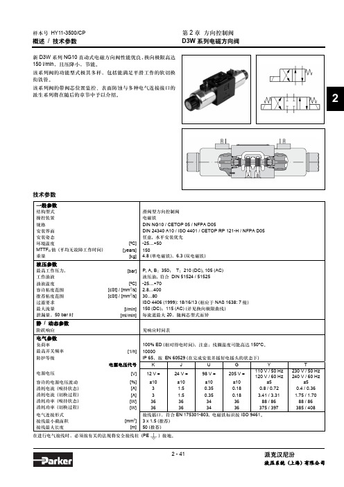
T 230 V / 50 Hz 240 V / 60 Hz
±5 0.4 / 0.36 1.75 / 1.70
88 / 86 385 / 408
2 - 41
派克汉尼汾
液压系统 (上海) 有限公司
样本号 HY11-3500/CP
订货代号
第 2 章 方向控制阀 D3W 系列电磁方向阀
D 3W
W
方向
规格
湿式 阀芯型式 阀芯位置 密封件 电磁铁 电气连接 电磁铁 换向响应 设计系列
派克汉尼汾
液压系统 (上海) 有限公司
样本号 HY11-3500/CP
性能曲线 换向极限
第 2 章 方向控制阀 D3W 系列电磁方向阀
下列曲线所示为各类 DC 和 AC 电磁铁阀的换向极限。对于阀芯 若油口 A 和 B 的流量不等,则换向极限将比图示的数值明显减 位置代号为 “F” 或 “M” 的阀,只能工作在 70% 换向极限以下 小。为了避免流量超过阀的换向极限,可以在油口 P 内插入安 的工况。图示的数值适用于流经油口 A 和 B 的流量相等的工况。 装一个节流塞。
液压参数
最高工作压力, 工作油液 油液温度 容许粘度范围 推荐粘度范围 过滤要求 最大流量 泄漏量,50 bar 时
静 / 动态参数
[bar]
[ºC] [cSt] / [mm2/s] [cSt] / [mm2/s]
[l/min] [ml/min]
P, A, B:350; T:210 (DC), 105 (AC) 液压油, 符合 DIN 51524 / 51525 -25…+70 2.8…400 30…80 ISO 4406 (1999): 18/16/13 (相应于 NAS 1638: 7 级) 150 (DC);115 (AC) (详见换向极限曲线) 每流道最大 20,随阀芯型式而异
Parker Hannifin 方向控制阀门目录说明书

Technical Information Series D1VA, D1VPGeneral DescriptionSeries D1VA and D1VP directional control valves are high performance, 4 and 5-chamber, direct operated, air and oil pilot controlled, 3 or 4-way valves. They are available in 2 or 3-position and conform to NFPA’s D03, CETOP 3 mounting patterns.Features• Low pilot pressure required.D1VA – 4.1 Bar (60 PSI) minimum D1VP – 15.2 Bar (220 PSI) minimumAir OperatedShift Volume. The air pilot chamber requires a volume of 1.8 cc (.106 in.3) for complete shift from center to end.Pilot Piston. The pilot piston area is 506 mm 2 (.785 in.2). Pilot piston stroke is 3.4 mm (.135 in.). Response Time. Response time will vary with pilot line size, pilot line length, pilot pressure, air control valve shift time and air valve flow capacity (Cv).Oil OperatedShift Volume. The hydraulic pilot chamber requires a volume of 0.7 cc (.042 in.3) for complete shift from center to end.Pilot Piston. The hydraulic piston area is 198 mm 2 (.307 in.2). Pilot piston stroke is 3.4 mm (.135 in.). Response Time. Response time will vary with pilot line size, pilot line length, pilot pressure, pilot valveshift time and oil valve flow capacity (GPM).Dimensions – Inch equivalents for millimeter dimensions are shown in (**)SpecificationsMounting Pattern NFP A D03, CETOP 3, NG 6 Operating: 345 Bar (5000 PSI) MaximumT ank Line: D1VA 34 Bar (500 PSI) PressureD1VP 207 Bar (3000 PSI)Maximum Flow See Reference Data D1V A :Air Minimum 4.1 Bar (60 PSI) Pilot Pressure Air Maximum 10.2 Bar (150 PSI) D1VP:Oil Minimum 15.2 Bar (220 PSI)Oil Maximum207 Bar (3000 PSI)AA B B P TAA BBP TOil Operated D1VP , Single and Double Pilot43.0(1.70)min.22.0(0.87)9.0(0.35)40.5(1.60)0.56(0.022)3.3 (0.13) max.X &Y Ports51.0(2.00)min.127.0(5.13)42.0(1.65)16.9(0.67)23.0(0.91)15.5(0.61)50.0(1.97)46.0(1.81)23.8(0.94)See NoteYSAE #41/4 BSPP (90)orNFPA D03CETOP 3Code Symbol001 002004008*009**020*026*030**081082* 008, 020 and 026 spools have closed crossover.** 009 and 030 spools have open crossover.Oil OperatorABP T ABP T ABP T ABP T ABP T ABP T ABP T# D available with 020 and 030 spools only.B & H available with 020, 026 and 030 spools only. E & K not available with 020, 026 and 030 spools.This condition varies with spool code.ABP T ABP T ABP TValve schematic symbols are perNFP A/ANSI standards, providingflow P to A when energizingoperator X. Note operators reversesides for #008 and #009 spools. See installation information for details.Directional Control ValveActuatorSpoolStyleDesign SealBasic ValveVariationsValve Weight: 1.90 kg (4.2 lbs.)Standard Bolt Kit: BK209 10–24x1.25Metric Bolt Kit: BKM209 M5–0.8x30mm Seal Kit:Nitrile SKD1VP FluorocarbonSKD1VPVBold: Designates Tier I products and options.NFPA D03CETOP 3Code D escription N NitrileV FluorocarbonCode Symbol001 002004008*009**081082* 008 spool has closed crossover.** 009 spool has open crossover.ABP T ABP T ABP T ABP T ABP T ABP T ABP TCode D escription Symbol Single operator, two position B spring offset.P to A and B to T in offset position. Double operator, C three position, spring centered. D Double operator, two position, detent. Two position, spring centered. E P to B and A to T in shifted position.Single operator, two position, H spring offset. P to B and A to T in offset position.T wo position, spring centered. K P to A and B to Tin shifted position.This condition varies with spool code.ABP T baABP TbaABPTbABP T aABP TaABPTbValve schematic symbols are per NFPA/ANSI standards, providing flow P to A when energizing operator A. Note operators reverse sides for #008 and #009 spools. See installation information for details.Directional Control ValveActuatorSpoolStyleDesign Series NOTE: Not required when ordering.SealBasic ValveVariationsValve Weight: 1.60 kg (3.5 lbs.)Standard Bolt Kit: BK209 10–24x1.25Metric Bolt Kit: BKM209 M5–0.8x30mm Grade 8 bolts required Seal Kit:Nitrile SKD1VA FluorocarbonSKD1VAVCode D escription Omit StandardP10* Monitor Switch 90 1/4 BSPP Threads * Not available on C & D styles.Not CE or CSA approved.A ir OperatorBold: Designates Tier I products and options.Dimensions Series D1VAInch equivalents for millimeter dimensions are shown in (**)Air Operated D1VA, Double PilotAir Operated D1VA, Single PilotNPT Typ.Note: 22.0 mm (0.87") from bottom of bolthole counterbore to bottom of valve.or。
Parker Hannifin 方向控制阀Series DS086C6M和DS096C6M技术说明说
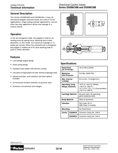
SpecificationsGeneral DescriptionThe Series DS086C6M and DS096C6m, 2-way, Bi-Directional poppet solenoid valves are used in on/off applications, single-acting cylinder applications, and all other two-way applictions where low leakage is a critical criteria.OperationIn the de-energized mode, the poppet is held on its seating area by spring force; blocking flow in both directions. In this mode, the maximum leakage is 10drops per minute. When the solenoid coil is energized,the poppet is shifted off of its seat allowing flow to pass in either direction.Features•Low leakage poppet design •Direct acting design•Standard valve bodies and common cavities•One-piece encapsulated coil with minimal amperage draw •Manual overrides, seal variations and other options available•Oil immersed armature solenoid, no dynamic seals •Numerous coil terminals and voltagesRated Flow 18.8 LPM (5 GPM)(At 70 PSI ∆P)Maximum210 Bar (3000 PSI)Inlet Pressure Max. Internal 2/3 cc/min. (10 drops/min.)Leakage Operating Temp.-40°C to +93.3°C (Nitrile)Range (Ambient)(-40°F to +200°F)-31.7°C to +121.1°C (Fluorocarbon)(-25°F to +250°F)Cartridge Material All parts steel. All operating parts hardened steel.Body Material Steel or Aluminum Filtration ISO Code 16/13,SAE Class 4 or better Mounting No RestrictionsCavityDS086C6Common Cavity No. C08-2DS096C6Common Cavity No. C09-2(2)Series DS086C6M and DS096C6M*Inch equivalents for millimeter dimensions are shown in (**)DimensionsCartridge OnlySeries DS086C6M and DS096C6MOrdering Information。
Parker Hannifin 模型 V11 方向控制阀门说明书
Bulletin HY14-2702-M1/US
Offer of Sale
The items described in this document and other documents or descriptions provided by Parker Hannifin Corporation, its subsidiaries and its authorized distributors are hereby offered for sale at prices to be established by Parker Hannifin Corporation, its subsidiaries and its authorized distributors. This offer and its acceptance by any customer ("Buyer") shall be governed by all of the following Terms and Conditions. Buyer’s order for any such items, when communicated to Parker Hannifin Corporation, its subsidiary or an authorized distributor ("Seller") verbally or in writing, shall constitute acceptance of this offer.
Bulletin HY14-2702-M1/US Service and Parts Bulletin
Model V11
Байду номын сангаас
- 1、下载文档前请自行甄别文档内容的完整性,平台不提供额外的编辑、内容补充、找答案等附加服务。
- 2、"仅部分预览"的文档,不可在线预览部分如存在完整性等问题,可反馈申请退款(可完整预览的文档不适用该条件!)。
- 3、如文档侵犯您的权益,请联系客服反馈,我们会尽快为您处理(人工客服工作时间:9:00-18:30)。
派克换向阀样本范文
派克换向阀(Parker Directional Control Valve)是一种用于控制
液压系统中流体流向的设备。
它通常由阀体、阀芯、阀孔和控制杆等组成。
派克换向阀一般用于工业设备、机械工程、农业机械、建筑机械等领域。
派克换向阀具有多种不同的工作方式,包括手动控制和自动控制两种。
手动控制方式可以通过人工操作来改变阀芯的位置,从而改变流体的流向。
自动控制方式可以通过外部信号来改变阀芯的位置,实现对流体流向的自
动控制。
派克换向阀还具有多种不同的功能,包括单向阀、溢流阀、节流阀等。
单向阀主要用于防止流体逆流,溢流阀主要用于调节流体的压力,节流阀
主要用于调节流体的流量。
这些功能可以根据不同的工作需求进行选择和
组合,从而实现对液压系统的精确控制。
除了基本的功能外,派克换向阀还可以根据用户的需求进行个性化定制。
例如,可以根据不同的工作场合选择不同的阀孔和阀芯结构,以满足
不同的流量和压力要求。
此外,还可以根据用户的需要进行材料和密封件
的选择,以适应不同的介质和工作温度。
派克换向阀还具有良好的节能和环保性能。
它采用先进的流体动力学
设计和优化的液压系统结构,能够减少能源的消耗和环境污染。
同时,它
还具有低噪音、高效率和长寿命等优点,在实际应用中可以大大提高设备
的工作效率和可靠性。
总的来说,派克换向阀是一种功能强大、性能稳定、可靠耐用的液压
控制设备。
它能够满足不同工作场合的需求,提高设备的效率和可靠性,
减少能源的消耗和环境污染。
因此,派克换向阀在工业生产和机械工程中具有重要的应用价值。
