正品Parker派克液位计FL69121特征
20种液位计工作原理及常见故障分析

20种液位计工作原理及常见故障分析3、钢带液位计它是利用力学平衡原理设计制作的。
当液位改变时,原有的力学平衡在浮子受浮力的扰动下,将通过钢带的移动达到新的平衡。
液位检测装置(浮子)根据液位的情况带动钢带移动,位移传动系统通过钢带的移动策动传动销转动,进而作用于计数器来显示液位的情况。
4、雷达液位计雷达液位计是基于时间行程原理的测量仪表,雷达波以光速运行,运行时间可以通过电子部件被转换成物位信号。
探头发出高频脉冲并沿缆式探头传播,当脉冲遇到物料表面时反射回来被仪表内的接收器接收,并将距离信号转化为物位信号。
5、磁致伸缩液位计磁致伸缩液位计的传感器工作时,传感器的电路部分将在波导丝上激励出脉冲电流,该电流沿波导丝传播时会在波导丝的周围产生脉冲电流磁场。
在磁致伸缩液位计的传感器测杆外配有一浮子,此浮子可以沿测杆随液位的变化而上下移动。
在浮子内部有一组永久磁环。
当脉冲电流磁场与浮子产生的磁环磁场相遇时,浮子周围的磁场发生改变从而使得由磁致伸缩材料做成的波导丝在浮子所在的位置产生一个扭转波脉冲,这个脉冲以固定的速度沿波导丝传回并由检出机构检出。
通过测量脉冲电流与扭转波的时间差可以精确地确定浮子所在的位置,即液面的位置。
6、射频导纳液位计射频导纳料位仪由传感器和控制仪表组成,传感器可采用棒式、同轴或缆式探极安装于仓顶。
传感器中的脉冲卡可以把物位变化转换为脉冲信号送给控制仪表,控制仪表经运算处理后转换为工程量显示出来,从而实现了物位的连续测量。
7、音叉物位计音叉式物位控制器的工作原理是通过安装在音叉基座上的一对压电晶体使音叉在一定共振频率下振动。
当音叉与被测介质相接触时,音叉的频率和振幅将改变,这些变化由智能电路来进行检测,处理并将之转换为一个开关信号。
8、玻璃板液位计(玻璃管液位计)玻璃板式液位计是通过法兰与容器连接构成连通器,透过玻璃板可直接读得容器内液位的高度。
9、压力液位变送器压力式液位计采用静压测量原理,当液位变送器投入到被测液体中某一深度时,传感器迎液面受到的压力的同时,通过导气不锈钢将液体的压力引入到传感器的正压腔,再将液面上的大气压Po 与传感器的负压腔相连,以抵消传感器背面的Po ,使传感器测得压力为:ρ .g.H ,通过测取压力P ,可以得到液位深度。
承德克罗尼-液位计LT100_c

!"#$%&' ()*+,-.
4
LT100
LT100
==== ====Cc ==== Uo Lc Io Po Co Lo !"#$%&"'()*+,-./)* ! !"#$%&'()* 130
!"#$%& '$()$*+ ~+60
!"#$%&'()*+,-./ -20 !"#$%&'()*+,-./ ! ! !"#
KROHNE 08/2006
LT100
!" LT100
!"#$% !" ! !" !"# ! !"# !
NO.QH05T00007
LT100
====LT100 !" !"#$
!"
!"#$%&' ()!&'
!"#$%&'()*+,-./
! M21 1.5
1W
====
!"#$%&'()*+,-)*
!"#!$%&' 12 100020 010-58797958 010-58797983 1 !"#$% 1911-1915
!==
! !"#$%&'()*+
!"#$%&'()*
LT100 M L-150
LT100
7
CRK
!
Foxboro 电浮筒液位计

Product Specifications12.2012PSS EML0710G-(en) 244LD Levelstar Intelligent Buoyancy Transmitter forLiquid Level,Interface and Densitywith Torque tube–HART-Version–The intelligent transmitter244LD LevelStar is designed to perform continuous measurements for liquid level,interfa-ce or density of liquids in the process of all industrial applications.The measurement is based on the proven Archime-des buoyancy principle and thus extremely robust and durable.Measuring values can be transferred analog and digi-tal.Digital communication facilitates complete operation and configuration via PC or control system.Despite extre-me temperatures,high process pressure and corrosive liquids,the244LD measures with consistent reliability and high precision.It is approved for installations in contact with explosive atmospheres.The244LD LevelStar combines the abundant experience of FOXBORO ECKARDT with most advanced digital technology.FEATURES•HART Communication,4to20mA •Configuration via FDT-DTM•Multilingual full text graphic LCD•IR communication as a standard•Easy adaptation to the measuring pointwithout calibration at the workshop•Linear or customized characteristic•32point linearisation for volumetric measurement •Backdocumentation of measuring point•Continuous self-diagnostics,Status and diagnostic messages•Configurable safety value•Local display in%,mA or physical units•Process temperature from–196°C to+500°C•Materials for use with aggressive media•Micro sintermetal sensortechnology2244LDPSS EML0710G-(en)PACTware:OperationFDT-DTM:ConfigurationSupply via power supply unit with communication;ExDirect supply with communication;not ExFurter supply circuits see Master Instruction document.PSS EML0710G-(en)244LD3TECHNICAL DATAData refer to the sensor material Type316L(1.4404) Explosion protection certificates must be observed! Input/OutputMeasuring ranges........50mm to50mupper and lower range valuecontinuously adjustable Standard lenghts ofDisplacer(204DE)........350..3000mm,14..120in;further lenghts on request Weight of displacer1)......max.25NMeasuring span..........2...20N contin.adjustable(to1N on request)Span ratioTurn-down..............1:1..1:10(1:20on request) Accuracy2).............±0.2%;increased accuracywith customized adjustment Transfer function.........linear or customized with upto32setpoints Configuration-with FDT-DTM per HART protocol-via2-wire connection4..20mA-via IR communication-with multi-lingual,full graphic LCD display with%,mA, physical units and2from the outside-to-use buttons Load.................R Bmax=(U S–12V)/23mACommunication HART Connection.............Two-wire systemSupply voltage U S3).......>12V+Rb*0.025ARb is the total burden resistor for lines,HART measure-ment resistor and communication.Current sink.............max.24mASignal range............4to20mAOperating range..........3.8to20.5mA(acc.NE43)Critical error alarms in the2-wire Communication..........<3.6mA and>21mA HART Protocol-2-wire................1200Baud,HART compliant -IR communication.......19200Baud Communication Hardware-Handterminal..........HT375/475-PC Software...........WINxx and FDT/DTM1)For measurement of interface or density:weight25N+buoyant force at lowest density2)Accuracy acc.ANSI/ISA-S51.1-19793)Us(max)with explosionproof device<30V,otherwise<42V Operating conditions4)Process temperature......–196°C...+500°C Pressure ratingacc.to DIN............PN16,40,63,100,160,250 acc.to ANSI...........Class150,300,600,900,1500 Ambient temperature5)6)...–40°C...+70°C7) Relative humidity.........up to100% Condensation...........permittedTransportation-storage temperature.......–40°C...+85°C Protection..............IP66(acc.DIN40050) The device can be operated at a class D2location in accordance with DIN IEC654,part1.Operation condition effectsAmbient temperature......–10°C...+70°CZero................<0.1%/10K8)Span...............<0.07%/10KTotal(0.1max.sp.0.07measured value±)%/10K (sp.=measuring span)<-10°C/>+70°C......twice the valueProcess temperature......<0.1%/10K8) Operating pressure.......no influence(vakuum resis-tant)Transitional behaviorDynamic behaviorDamping(90%-time).....0...32sSwitch-on time.........7sStep response(63%-time)with damping0s........250msUpdate rate.............10/sLong term stability........<0.2%/6months at20°C8) Noise suppressionCommon mode voltage...<AC250V effCommon mode rejection..120dBSeries mode rejection....50dB Filter.................Smart Smoothing4)Not with all materials–see Table of Comparison of Materials page65)Ambient temperature must not exceed50°C at measuring modulehousing,when process medium or heating of medium exceed300°C6)–50°C on request7)Display not readable at T<–20°C or T>+70°C8)For max.measuring span4244LD PSS EML0710G-(en)Material,Pressure Rating&Contact Face,Mounting Directionsee Model CodesMaterial Amplifier housing..Aluminum(Alloy No.GD-Al Si12),Polyurethan coatedor Stainless SteelFor Sour Gas applications acc.to NACE Standard MR-0175-95: Wafer body............316L(1.4404)Torque tube...........Hastelloy C or Inconel600 The material of the seal at the Torque tube bearing corre-sponds to the material of the head piece.MountingMounting method.........sandwich mountedacc.to DIN............DN80,DN100acc.to ANSI...........3inch,4inchNote:Always follow the RH or LH version!See the picture below.The device can not be used“upside down”.All inter-nal parts are mounted and calibrated in inverse manner. The conversion can be performed only by the manufacturer or a contractual partner.Otherwise calibration and pressure test are invalid.Weight Transmitter.............see table page7 Displacer...............see table page10Electrical connectionCable entry thread........M20x1.5or1/2-14NPT Cable gland and screwed sealing plug have to be ordered separately under model code BUSG...For equipment in Ex d version,1screwed sealing plug made of stainless steel is included in delivery.Screw terminals..........wire cross-section up to2.5mm²Test sockets............Ø2mm Electromagnetic compatibility EMCOperating conditions......industrial environment Immunity according toEN61326(3/2002)......fulfilledEmission according toEN61326(3/2002)......fulfilledEN55011,May2000,Group1,Class A........fulfilledEN50081-2............fulfilledNAMUR recommendation Ne21Status Aug.1998fulfilled SAFETY REQUIREMENTSCE LabelElectromagnetic compatibility............2004/108/EC fulfilled Explosion protection acc.to ATEX...94/9/ECSafetyAccording to EN61010-1(resp.IEC1010-1)........safety class IIIInternal fuses............none(or not replaceable bycustomer)External fuses...........Limitation of power supplies for fire protection have to be observed due to EN61010-1, appendix F(rsp.IEC1010-1)PSS EML0710G-(en)244LD5Electrical classification ATEX 2)3)intrinsic safe:AID 421II 1/2G EEx d ib/ia IIC/IIB T4/T6PTB 04ATEX 2011X Zone 0AID 421II 2G EEx d ib/ia IIC/IIB T4/T6PTB 04ATEX 2011X Zone 1explosion-proof:AD 432II 1/2G Ex da/db IIB/IIC T4/T6PTB 02ATEX 1025X Zone 0AD 432II 2G Ex da/db IIB/IIC T4/T6PTB 02ATEX 1025XZone 1Zone 2:Manufacturer’s DeclarationFurther certificates see also our website:http://www.foxboro-eckardt.eu/Ex_de_en/allEX_244LD_en_de.html -FM -CSA -NEPSI -Russia-Kasachstan-Approvals for use on sea ships2)With appropriate 3)National6244LD PSS EML0710G-(en) Comparison of MaterialService Limits of wafer body PN250made of(material)Max.operating pressure in bar at temperature in°CTable of Weights1)Values on requestPSS EML0710G-(en)244LD78244LD PSS EML0710G-(en)(continued)PSS EML0710G-(en)244LD9(continued)10244LD PSS EML0710G-(en) Displacer204DETypical Dimensions and Weights for Density RangesΔρ1)1)Δρ=ρ1-ρ2ρ1=density of lower mediumρ2=density of upper medium2)Using displacer material1.4571can cause small devia-tions in diameter,volume and weight.3)For measurement of interface or density,the max.den-sity of the lower medium is1350kg/m³.4)Min.density of the lower mediumIf a Displacer Chamber is used,the difference bet-ween the diameter of the Displacer and the inside diameter of the Displacer Chamber must be at least 10mm.Lengths<350mm and>3000mm,and density ran-ges<100kg/m³and>2000kg/m³on request.AccessoriesFor Displacer Chamber204DC,Flange combination 204FK and Cover Flange Kit204BCF see PSS EML0901,204..Accessories for Buoyancy Transmitter.(continued)Table of versions for dimensions c,d,g see drawing on next pageVersion Form of Sealings DN80/3inch DN100/4inch PN c d g c d gDIN EN 16B1DIN EN1092B2/C/D/F/EDIN EN109214082140160102162 4063100Form L DIN2696160250ANSI 150RF/SG/STANSI B16.514082140160102162 3006009001500150RJFANSI B16.514082140160102174 3001476009001500102162206 300LF/LM/LG/LTANSI B16.514082140160102174 6009001500RF Raised Face RJF Ring Joint Face LF Large Female LM Large Male LG Large Groove LT Large Tongue SG Small Groove ST Small TongueDIMENSIONS244LD up to PN250/Class1500Subject to alterations -reprinting,copying and translation prohibited.Products and publications are normally quo-ted here without reference to existing patents,registered utility models or trademarks.The lack of any such refe-rence does not justify the assumption that a product or symbol is free.FOXBORO ECKARDT GmbH Pragstr.82D-70376Stuttgart Tel.+49(0)711502-0Fax +49(0)711502-597Mail to:salessupport@foxboro-eckardt.de http://www.foxboro-eckardt.euDOKT 556588038~1Product Specifications for Intelligent Transmitters Product Specification:Device:PSS EML0610144LD Intelligent Buoyancy Transmitter for Liquid Level,Interface and Density with Displacer and Torque TubePSS EML0710A 244LD Intelligent Buoyancy Transmitter for Liquid Level,Interface and Density PSS EML0710G with Displacer and Torque Tube (A:TransStar G:LevelStar )PSS EML1610144LVD Intelligent Buoyancy Transmitter for Liquid Level,Interface and Density with DisplacerPSS EML1710244LVP Intelligent Buoyancy Transmitter for Liquid Level,Interface and Density with DisplacerPSS EML0901204xxAccessories for Buoyancy Transmitters PSS EMO0100Accessories for Devices with HART-Protocol。
FLOWLINE LU8X超声波液位计说明书

B.进入编辑模式
按住 SELECT/FAST 键大约 5 秒种,直到 LCD 显示屏从数 字变成字母 PROG,即表示以进入了编辑模式。 注意:当进入编辑模式,电流输出会保持在最后一个以 知数值,直到回到测
量模式。
地址:北京朝阳区北苑路甲13号院北辰新纪元大厦2-1702 邮编:100107 电话:(010)84917838 传真:(010)84917838
1. 按住 SELECT/FAST 键 5 秒进入一级菜单。 2. 当 LCD 显示屏出现 UNITS 时,按 SELECT/FAST 键。
显示会改为 INCHES,CM,PERCENT 和 DISPLAY 循环 显示。 3. 当屏幕上显示 DISPLAY 时,按 SELECT/FAST 键。显 示会改为 AIR 和 LIQUID 循环显示。 4. 当屏幕上显示您所需要的模式时,按 SELECT/FAST 键。比如您需要显示为液位(LIQUID),则在 LCD 显示屏出现 LIQUID 时,按 SELECT/FAST 键。
4. 按 UP/DOWN 键增加或降低此数值,直到与以知的满液 位点到罐低的距离相等。注意:同时按 SELECT/FAST 和 UP/DOWN 键会增加数值改变的速度。
5. 最后按 SELECT/FAST 键保存。 现在您已经成功设置了满罐高或 20mA。
I.编辑颠倒 mA(REV mA)参数。
仪表出厂时默认 4mA 在最大量程(MaxR),20 mA 在最大
会改为 HEIGHT,FILL H 和 REV mA 循环显示
D.Display Mode(显示模式) 仪表出厂时统一设定为显示探头下表面到液面(或其他反 射面)的距离,这一般称为空高。当液位增加时,显示会 相应减少。同时,仪表也可以被设定为显示罐底到液面的 距离(液位)。下面的示例中,一个 100 英寸高的罐,在 空高模式显示为 40 英寸,而在液位模式则显示为 60 英寸。
液位开关说明书

外贴式液位开关隔爆型安装使用说明书(201405A)陕西声科电子中国西安高新技术产业开发区©本说明书的版权和最终解释权归声科电子有限公司所用。
目录1.使用说明 (1)2.仪表保修及服务范围 (1)3.仪表技术性能 (2)4.开箱检验及注意事项 (2)4.1 开箱检验 (2)4.2 注意事项 (3)5.仪表各部件 (3)6.仪表安装 (4)6.1 超声波探头的安装 (4)6.2 仪表主机安装 (8)6.3仪表的安装方式 (11)7.仪表电气连接 (12)7.1 仪表电气连接图 (12)7.2 仪表供电 (12)8. 仪表设置及使用 (13)8.1 仪表参数设置人机接口说明 (13)8.2 仪表操作目录树 (14)8.3 仪表运行界面示意 (15)8.4 仪表校准操作 (16)8.5仪表校准操作图示 (16)9.外贴式液位开关选型表 (19)10.仪表适用范围 (20)11.性能指标 (20)12.仪表故障处理 (21)1、使用说明本说明书全面阐述了外贴式液位开关的安装、操作及使用方法。
通过本说明书,用户可以顺利的完成对外贴式液位开关的安装、使用及维护工作。
本说明书的编制是以外贴式液位开关的安装、操作步骤为顺序,详细介绍了您在安装、使用仪表的每个环节需要完成的工作及注意事项。
在您安装、使用该仪表之前,请详细阅读本说明书。
2、仪表保修及服务范围自发货之日算起,仪表主机保修期为一年,仪表修理及维护的保修期为半年,此保修仅限于原始购买者及或声科电子指定经销商的仪表使用用户,而不适用于任何声科电子认为因错误使用,改造、疏忽或因事故及非正常情况下使用而导致损坏的仪表。
对于在保修范围内的送回声科电子的有故障的仪表,声科电子提供免费维修。
要获得保修服务,请联系声科售后服务部并附上故障说明,经本公司许可后,将仪表寄往声科售后服务部。
如果仪表已过质保期或声科电子确认仪表故障是由于错误使用、改造、疏忽、事故及非正常条件下使用导致的,声科电子将依据外贴式液位开关维修收费标准提供维修费用预算,并在得到认可后进行维修。
Parker Hannifin Veriflo 945Y Series高压气体阀门说明说明书

VerifloContact Information:Parker Hannifin Corporation Veriflo Division 250 Canal BlvdRichmond, California 94804phone 510 235 9590fax 510 232 7396************************/verifloMobile App: /verifloValue Proposition:The 945Y valve offers thesame benefits as the standard two way valve. The “Y” valve configuration allows for a mix of operator combinations, reduces space requirements, and has fewer welds over standard valve alignments.Pressure and flow requirements are unique to each valve in this offering, please reference the two way data sheet to ensure proper selection.UHP Stainless Steel Diaphragm Valve High Pressure Manifold945Y SeriesProduct Features:• 100% Helium leak tested •Standard full internal electropolish•Minimal particle generation and particle entrapment areas• Vericlean ™, Veriflo’s low sulfur high purity 316L Stainless Steel enhances electropolishing, welding, and corrosion resistance• Standard surface finish of 10 micro inch Ra• Internally threadless and springless• Unique compressionmember which loads the seal uniformly without the needfor threaded components or crimping operations • Fully functional from vacuum to 3500 psig945Y1NO/NCFSFFFA945Y1NO/NCFSFFFB945Y SeriesDimensional Drawings945Y1NO/NCFSFFFA945Y1NO/NCFSFFFB945Y1M/NCFSMFFAConnection 1V1-First ValveConnection 3V2-Second ValveConnection 2945Y1M/NCFSMFFA Basic Series45Y = 945YFlow Path1 = Down Stream Purge2 = Up Stream Purge3 = CommonActivating Device Type (V1/V2)HP = Air Operated, High Pressure, Normally Closed HP can only be used in combinationwith HP or M actuatorsNC = Air Operated, Low Pressure, Normally Closed NO = Air Operated, Low Pressure, Normally Open M = Mini-LeverPort StyleFS = 1/4” Face Seal FS8 = 1/2” Face Seal TS = 1/4” Tube Stub TS6 = 3/8” Tube Stub TS8 = 1/2” Tube StubPort ConfigurationM = Male Face Seal F = Female Face SealOptional FeaturesPEEK = PEEK™ SeatsVESP = Vespel® Seats Recommendedfor Nitrous Oxide (N2O) ServiceDimensionsDimensions applicable to all actuating device types except HP . For HP actuating device typedimensions, see table below.A = 4.69 x 2.15B = 4.06 x 2.66 FSF or TS Only.1467512345679 45Y 1 NC/NO FS MMF VESP A945Y1NC/NOFSMMFVESPA Sample:Finished Order:23Ordering ExampleBuild a 945Y Series valve by replacing the numbered symbols with an option from the corresponding tables below.Contact factory for most up to date lead time information.Blue = Configurations that have selections in blue may have an extended lead time and a minimumorder quantity.LitPN: 25000015 Rev: H Date of Issue 09/2016© 2009 Parker Hannifin CorporationVerifloOFFER OF SALE:The items described in this document are hereby offered for sale by Parker-Hannifin Corporation, its subsidiaries or its authorized distributors. This offer and its acceptance are governed by the provisions stated in the detailed “Offer of Sale” elsewhere in this document or available at /verifloWARNING USER RESPONSIBILITYFAILURE OR IMPROPER SELECTION OR IMPROPER USE OF THE PRODUCTS DESCRIBED HEREIN OR RELATED ITEMS CAN CAUSE DEATH, PERSONAL INJURY AND PROPERTY DAMAGE. THIS DOCUMENT IS FOR REFERENCE ONLY. PLEASE CONSULT FACTORY FOR LATEST PRODUCT DRAWINGS AND SPECIFICATIONSThis document and other information from Parker-Hannifin Corporation, its subsidiaries and authorized distributors provide product or system options for further investigation by users having technical expertise.The user, through its own analysis and testing, is solely responsible for making the final selection of the system and components and assuring that all performance, endurance, maintenance, safety and warning requirements of the application are met. The user must analyze all aspects of the application, follow applicable industry standards, and follow the information concerning the product in the current product catalog and in any other materials provided from Parker or its subsidiaries or authorized distributors.To the extent that Parker or its subsidiaries or authorized distributors provide component or system options based upon data or specifications provided by the user, the user is responsible for determining that such data and specifications are suitable and sufficient for all applications and reasonably foreseeable uses of the components or systems. The products described herein, including without limitation, product features, specifications, designs, availability and pricing are subject to change by Parker Hannifin Corp and it’s subsidiaries at any time without notice.Proposition 65 Warning: This product contains chemicals known to the state of California to cause cancer or birth defects or other reproductive harm.Vespel® is a registered trademark of DuPont Performance Elastomers L.L.C.Elgiloy® is a registered trademark of Elgiloy Company VeriClean™ is a trademark of Parker Hannifin CorporationPEEK™ is a trademark of Victrex plc.Use mobile device to scan this QR Code.For additional information on materials of construction, functional performance and operating conditions, please contact factory.。
常见的液位计及优缺点

常见的液位计及优缺点陕西声科电子科技有限公司编辑整理目录1、磁翻板液位计2、玻璃板液位计3、玻璃管液位计4、浮筒液位(界面)计5、大浮球液位变送器6、差压液位计7、静压液位计8、脉冲雷达液位计9、导波雷达液位计10、磁致伸缩液位计11、射频导纳电容液位计12、超声波液位计(顶装)13、伺服液位计14、Ý射线液位计15、激光液位计16、重锤液位计1、磁翻板液位计(磁浮子液位计)工作原理:浮力原理和磁性耦合作用研制而成应用范围:高温磁翻板液位计适合在高温高压的液体里面进行测量的,液位介质最高温度可达450度。
被广泛应用到石油化工、食品、环保冶金等行业中。
由于介质完全密封在液位计中,所以对于易燃、易爆、有毒、腐蚀的液体非常适用。
使用限制:测量介质无杂质或者很少的杂质;不粘稠,不结晶。
精度等级:精度在±-±10mm之间。
市场价格:1500左右优点:1、测量通道是段光滑直管,不会阻塞,适用于测量含固体颗粒的液固二相液体,如纸浆、泥浆、污水等;2、不产生流量检测所造成的压力损失,节能效果好;3、所测得体积流量实际不不受液体密度、粘度、温度、压力和电导率变化的明显影响;4、流量范围大、口径范围宽;能够快速、直观地读数;价格较低;可实现远传和调节;体积较小,容易实现远传和调节;适用于具有腐蚀性和高压介质。
缺点:精度较低,测量精度一般在±-±10mm之间;安装复杂;有一定量程限制;不能测量气体、蒸汽和含有较大气泡的液体;不能用于较高温度;大量磁翻板液体计运输不方便,且安装体积较大。
2、玻璃板液位计工作原理:连通器原理,液位计两头接待测容器液面上下,保持压力一致,液位计里的液面高度就近似容器内液面高度。
应用范围:它主要用于直接显示各种罐、塔、槽、箱等容器内介质液位的高度。
使用限制:容器中的介质必须是与钢、钢纸及石墨压环不起腐蚀作用的。
精度等级:±1cm市场价格:<1000优点:读数清晰、直观、可靠;结构简单、维修方便;经久耐用缺点:1.厘米显示,精度差2.对介质有要求,不能测量与钢、钢纸及石墨材质不起腐蚀作用的介质3.大量程运输不方便,常温常压下汽化的介质测量误差大或无法测量3、玻璃管液位计工作原理:玻璃管液位计是利用连通器原理测量容器内的液位。
E+H射频导纳液位计
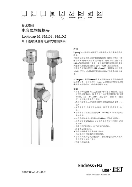
Level Pressure Flow Temperature Liq u idA n a ly sis Registration SystemCompo n entsSe r vi ces S olu t io ns技术资料电容式物位探头Liquicap M FMI51, F MI52用于连续测量的电容式物位探头T I 401F/28/z h/04.0 7/(09. 07) 应用Liquicap M一体化型变送器可对液体物料进行连续的物位测量。
其经测试验证的坚固耐用的机械结构(锥形自密封)确保了探头既可在真空环境中使用,也可在压力值高达100bar的过压环境中使用。
采用的密封及绝缘材料使探头适用于操作温度范围为-80℃…+200℃的应用场合。
当被测介质的电导率>100μS/cm时,测量与介电常数(DK)无关,此时测量不同液体物料时无需重新标定探头。
与Fi e l dg a t e(采用I n t er n et技术的智能仪表远程监控和数据采集设备)配合使用时,L i q u i c ap M能为原料库存及优化物流(存量控制)提供理想解决方案。
优势·对电导率为100μS/cm的液体物料进行测量时,无需对探头进行标定。
探头的出厂标定是根据用户所订购的探头长度(0%...100%)来进行的,因而用户能简便、快速地对探头进行调试。
·通过纯文本显示方式实现菜单引导式的现场设置(可选)。
·仪表获取了多项证书和认证,因而应用范围十分广泛。
·可应用于功能安全需满足IEC 61508的S I L2标准的安全系统之中。
·与介质接触部分由防腐材料和F DA认可的材料制成。
·具有两级防罐体放电(气体放电和保护二极管)的过压保护。
·介质中有粘附物时,电子部分仍可动作。
·测量值反应时间短。
·更换电子插件无需重新标定仪表。
·自动开启电子插件的自监控功能。
捷克精密压力仪表参数
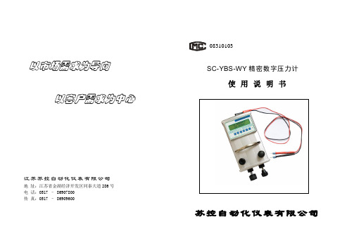
以市场需求为导向以客户需求为中心江苏苏控自动化仪表有限公司地 址:江苏省金湖经济开发区同泰大道286号 电 话:0517 – 86907800 传 真:0517 – 8690960008310103SC-YBS-WY 精密数字压力计使用说明书苏控自动化仪表有限公司注:1公斤力/厘米=1工程大气压=10公斤力/米=9.80665*104牛顿/米2(帕斯卡)=0.980665巴=0.967841标准大气压=10米水柱(4℃,g=9.80665米/秒2)=735.559毫米汞柱(0℃,g=9.860665米/)=14.223磅/英寸21巴=105牛顿/米2(帕斯卡)=10197.2公斤力/米2=1.01972公斤力/厘米2=14.5038磅/英寸2=750.062 毫米汞柱(0℃,g=9.80665米/秒2)=1.01972*104 毫米水柱(4℃,g=9.80665米/秒2)1公斤力/米2=1.000028毫米水柱(4℃,g=9.80665米/秒2)=1.001797(20℃,g=9.80665/米秒2)毫米水柱。
1标准大气压=101325牛顿/米2(帕斯卡)=10332.27公斤力/米2=760毫米汞柱(0℃,g=9.80665米/秒2)目录附录一: 压力单位换算表一、概述 (1)二、技术指标 (2)三、用途 (3)四、仪器组成 (4)五、使用操作 (5)六、注意事项 (7)七、附件 (8)八、附录 (10)前言衷心感谢贵单位使用我公司生的精密数字压力计,使用前请仔细阅读使用说明书,以期您在使用时得心应手。
该精密数字压力计是我公司根据多年生产经验及市场需求,经科研技术人员精心设计,软硬件齐全,性能稳定可靠,使用广泛的又一系列产品。
为使您快速正确掌握该系列产品的使用方法,本使用说明书详细地介绍了该系列产品的技术指标、用途、仪器组成、使用操作、注意事项等。
使用前务请仔细阅读使用说明书,以期永处地保证该系列仪表的可靠性和稳定性。
PS690U系列保护测控装置技术使用说明书V1.3
2009-12-24
2009-12-11 2009-7-27 2008-4-2 修改日期
* 技术支持
电话:(025)83537262
传真:(025)83537201
* 本说明书可能会被修改,请注意核对实际产品与说明书的版本是否相符
* 2010 年 8 月 第 1 版 第 1 次印刷
各种液位计说明书

公司简介北京铁强科技发展有限公司,位于我们伟大的首都——北京,是一家以工程仪表生产、研发为主的科技型企业,是一个极具活力与前景的多元化的新型民营企业。
公司技术力量雄厚,依靠北京的人才、技术、信息等优势,自2000年成立以来,通过短短七年多时间,就在仪器仪表生产制造领域内谱写一个又一个神话。
公司先后与北仪集团、德国西门子公司、美国麦克公司等仪表生产制造商进行广泛而深入的合作,在合作中公司产品的品质和质量得到很大提升。
同时,公司也在积极借鉴和引进国外先进技术和生产工艺,产品的科技含量不断提高、种类也在不断丰富。
另外,公司不断以新技术、新工艺、新材料、新设计理念设计生产品质高、性能优、用途广、使用寿命长的产品。
公司自主生产磁翻柱液位计、浮球液位计(液位开关)、钢带液位计、磁致伸缩液位计、微波物位计、电容式液位计、超声波液位计、音叉物位开关、电容式物位计、差压变送器等物位测量仪表。
同时,公司还经营流量仪表、压力仪表、温度仪表以及成分分析仪表等自动化测量、控制仪表。
经过几年的努力,公司发展了一支专业化、国际化、规模化的研发、生产、和管理团队。
公司现有员工100余名,其中有高级职称的技术人员5人、大专及以上各类专业人才80余名。
是“中国石化物资资源市场成员”单位;是“中国石油天然气集团公司一级供应网络”单位。
是众多国内外用户的高品质、可信赖的工业计量器具服务商。
公司一直秉承“技术为本,质量为先,笃信予人,益精致远”的经营理念,以“更强、更大、更实”为经营宗旨,开拓进取,务实创新,在做好产品生产和经营的基础上,还以打造中国仪表名牌为己任,投资开发有自主知识产权的产品。
在发展过程中,公司始终以快速的反应、精湛的技艺、热忱的服务及时为用户排忧解难,也因此得到了广大用户与社会各界的一致认可。
如今,公司全体员工正走专业化、特色化、精细化经营之道,并朝着两年时间内年销售额翻两番的目标奋力前进!北京铁强仪表科技发展有限公司产品选型样本目录01、磁翻柱液位计 (3)02、浮球液位计(液位开关) (5)03、防爆浮球液位开关 (7)04、玻璃板式液位计 (8)05、玻璃管式液位计 (10)06、钢带液位计 (12)07、重锤探测液位计 (14)08、超声波物位计 (15)09、智能雷达液位计 (17)10、导波雷达液位计 (19)11、电容式液位计 (21)12、射频导纳物位控制器 (23)13、音叉物位控制器 (25)14、磁致伸缩物位计 (27)15、压力液位变送器 (29)16、小型浮球液位计(液位开关) (31)17、常用客户名单 (32)注:我们是一家专业生产物位仪器仪表的科技型公司,随着市场的需求变化、我们的技术人员也会在保证质量的前提下,对产品进行改进,改造后的产品外观会有所变化、性能也会有所提高。
Parker Hannifin 水管产品分公司产品说明书

A s s e m b l y E q u i p m e n tDAH o s eBCEFGF i t t i n g sP a r k r i m p C r i m p i n g E q u i p m e n tA d a p t e r sA c c e s s o r i e sA p p e n d i c e sHose Assembly EquipmentCatalog 4400 US Hose Assembly EquipmentVisual IndexHose Assembly EquipmentCatalog 4400 US Model No. 2726 - Mandrel Tool Kit - 23 Series (SAE45°&PTT30°)Visual IndexTH8-400 - Production CrimperModel No. 339 & 239 - Hose Cut-Off MachineModel No. 332T-115V - Hose Cut-Off Machine Model No. 631075 - Karrykut -Hose Cut-Off MachineModel No. 871522 -Handycut -Hose Cut-Off MachineModel No. 881540 -Push-Lok Cut-Off & Assembly ToolModel No. 316 - Hose Cut-Off ToolModel No. TH11-1 - Hose Cut-Off ToolModel No. TH9-1 - HoseInsertion Depth Blocks (Gauges)Model No. TH2-7 - Fittings Push-On Stand Model No. 432-115V -Hozembler & StandModel No. 80C-SDR - Swivel Die RackModel No. 80C-0DR - Die Storage RackHoze-OilAccrolube - High Efficiency Lubricant601069- Hose PerforatorModel No. 652200 - Mandrel Tool Kit - 22 SeriesModel No. 2727 - Mandrel Tool Kit - 23 Series (JIC 37° Flared)Model No. 652201 - Assembly Tools - 22 SeriesHydraulic Hose and Flow Capacity GuideD-3D-9D-4D-4D-5D-5D-5D-5D-6D-6D-6D-7D-7D-7D-8D-8D-8D-8D-9D-9Hose Assembly Equipment Catalog 4400 USProduction CrimperTH8-400♦Specifications· Power:230 Volts 3 Phase 60 Hz· Weight:1000 lbs· Width:27 inches· Depth:44 inches· Height:58 inches· Height to center of dies:48·1/2 inches· Capacity:1-1/4" SAE 100R1AT Max.1" DIN 20 022-1SN Max.1-1/4" SAE 100R2AT Max.1-1/4" DIN 20 022-2SN Max.1" SAE 100R3 Max.1-1/4" SAE 100R4 Max.7/8" SAE 100R5 Max.7/8" SAE J1402 AI Max.7/8" SAE J1402 AII Max.1-1/4" SAE 100R9 Max.1-1/4" SAE 100R12 Max.1" SAE 100R16 Max.1-1/4" SAE 100R17 Max.· Cycle Time: 301-8 (1/2" SAE 100R2A T) — 4 seconds perstraight end fitting· Die Changeover Time: One piece cartridge — less than 60seconds♦Features· Enclosed power unit.· One piece quick set-up cartridge die.· Foot pedal operated.· Ten sets of dies will cover the entire range of hoseand fittings through 1¼” (-20) SAE100R12, requiring 43and 71 Series coupling through -20 size.· Die storage area within cabinet.· Horizontal feed to improve cycle time.· Some die sets will handle more than one type andsize: e.g., one set will handle 43 Series (-8) and 71Series (-6), while another will handle 43 Series (-10)and 71 Series (-8).Standard die sets available are:Fitting Series Size26 Series-4 through -2043 Series-4 through -2071 Series-6 through -20Other dies sets are available upon request.♦Optional ToolingDie Set43 Series71 SeriesPart Number Size SizeTH8-400DC16-4TH8-400DC18-5TH8-400DC21-6TH8-400DC24-8-6TH8-400DC27-10-8TH8-400DC31-12-10TH8-400DC34-12TH8-400DC40-16TH8-400DC43-16TH8-400DC50-20-20Die Set26 SeriesPart Number SizeTH8-400DC26-4-4TH8-400DC26-5-5TH8-400DC26-6-6TH8-400DC26-8-8TH8-400DC26-10-10TH8-400DC26-12-12TH8-400DC26-16-16TH8-400DC26-20-20Production CrimperHose Cut-Off MachineModel No. 339 and 239Model 339Designed for heavy duty use. Will cut multi-braided wire reinforced hoses including 6 heavy spiral constructions up to 2" inside diameters. Model 339 comes equipped with 2 cut-off blades of a special scalloped construction. Equipped with 3 HP motor 230V, 3 phase, 60 cycle.Dimensions:22" wide x 42" long x 24" high Shipping Weight:115 lbs. Replacement Scallop Cutting Blade (10" with 3/4" arbor size) Part No. 24248 Replacement Smooth Cutting Blade Part No. 15960 Model 239This is Model 339 with 230V single-phase motor Part No. 239 For additional information see Bulletin #4497-B11.Hose Cut-Off MachineModel No. 332T-115VPower unit for quick, easy cutting of cotton or rubber covered fabric braid or wire reinforced hose. Equipped with 1-1/2 HP, 3450 RPM, 115/230V single phase electric motor wired for 115V. Belt driven cutting wheel of high speed steel, hardened and ground for smooth, dust-free, long-lasting service. Moving parts shielded by guards. Includes a Smooth Cutting Blade (8" with 5/8" arbor size)Model 332T-115V will cut:two wire braid, 1-1/4" maximumone wire braid, 2" maximumfour spiral, 1-1/4" maximumReplacement Smooth Cutting Blade (8" with 5/8" arbor size)Part No. 580661 Replacement Scallop Cutting Blade Part No. 24398Hose Cut-Off Machine - Karrykut Model No. 631075A portable power saw for cutting on the job. Hardened steel blade powered by 115V (13 amp) universal AC motor. Hand grip, trigger control. Unique clamp spreads hose as it is cut to prevent binding of blade.Cuts rubber and cotton covered, wire or fabric reinforced hose from: 1/4" through 2" inside diameter.Cuts 4 spiral light wire hose: 1-1/4" maximumUniversal Clamp Attachment:Part No. 631076 Universal clamp attachment may be used with any portable power saw unit having a 5/8" arbor, 8" blade capacity.Replacement Cutting Blade (8" with 5/8" arbor size):Part No. 580661 Replacement Power Saw (less clamp and blade):Part No. 631140 Hose Cut-Off Tool - HandykutModel No. 871522Handykut is a portable tool designed for efficient cutting of hose. Once Handykut is positioned onto a flat surface by clamps or by locking it in a vise, properly align the hose in a radius and cut it with a hacksaw.Push-Lok Cut-Off & Assembly Tool Model No. 881540This unique tool combines a hose cutter with a toggle-action that presses the fitting into the hose.Designed to handlePush-Lok hose from 1/4" through 3/4", this tool makes the job easier whether you are making one assembly or a hundred. Overall length:16" Weight:Approximately 4 pounds Hose Cut-Off ToolModel No. 316Model 316 hose cut-off tool is a small size, easy to use, manually operated unit for quick cutting of Parker 235, 293, 601, and 604 hoses. It can also be used for Push-Lok hose 801, 804, 821, 821FR, 831 and 836. Ruggedly built for yearsof trouble-free service.Hose Cut-Off ToolModel No. TH11-1Parker Push-Lok cutters are designed for quick, easy cutting of Push-Lok hose in all sizes and non-wire reinforced hose. TH11-1squarely cuts Push-Lok hose 1/4" I.D. through3/4" I.D.Hose Insertion Depth BlocksFor quick and easy marking of hose insertion depth. A faster way to leak-free assemblies.Ensures accuracy. Increase productivity.The first step toward a leak-free hose assembly is accuratelymarking the proper hose insertion depth. This is a fail-safe way to quickly and easily mark proper insertion depth, each and every time. With aluminum blocks and steel mandrels, Hose Insertion Depth Blocks feature a range of sizes clearly designated for a specific fitting series.Note: For additional information, please see Bulletin #4480-B53-USA.Hose Cut-Off Tool, Hose Insertion Gauges,and Fitting Push-On StandFitting Push-On Stand Part No. TH2-7Fitting Push-On Stand is the fastest way to make Parker hose assemblies in production volumes.Quickly and easily pushes fittings onto hose.Boosts productivity and quality. Reduces worker fatigue. The Push-On Stand eliminates the need of rubber mallets, oils and a lot of elbow grease to get fittings all the way onto the end of hose for crimping. Comes complete with straight tooling required for sizes -4 to -32, all permanent series, 82 Push-Lok, and 88 series field attachable fittings. Elbow Pusher Set (TH2-7-ELS) available.Note: For additional information, please see Bulletin #4480-B36-USA.Die Racks and HozemblerHozemblerModel 432-115VThe 432 Hozembler is a power machine to facilitate the attachment of reusable hose fittings. It readily handles all types of hose and fittings in sizes -3 through -32 I.D., including standard bent tube elbow. The 432 will also handle assembly of 4 heavy wire spiralthrough -24, I.D.115V, 30 amp, universal AC motor. Model 432 is supplied complete with foot switch and safety guard.Model 432 Hozembler (complete with vise and all adapters)Part No. 432-115VMounting stand:Part No. 662451Replacement PartsHose vise (complete with 662453 and 662454)Part No. 662452Hose vise jaw plate Part No. 662453Hose vise jaw adapter Part No. 662454Chuck jaws Part No. 662455Chuck jaws adapter set for use with most bent tube ends and hose fitting hex sizes up to 1/2".Part No. 662456Request Bulletin # 4497-B2 for operating instructions.Swivel Die Rack Part No. 80C-SDRHolds up to 30 dies. Accommodates any size Parkrimp die. Powder-coated, heavy-duty steel construction.The convenient new Swivel Die Rack, organizes and stores your collection of dies so they're always ready to work when you are. The Swivel Die Rack consists of a base unit and up to five circularholders, each with the capacity to hold five or six dies. It is floor or bench mountable.Note:For additional information, please see Bulletin #4480-B54-USA.Die Storage Racks 80C-0DR and 83C-0DRThe 80C-0DR and 83C-0DR Die Storage Racks are modular die rack designed to hold small and large Parkrimp dies.The 80C-0DR will store three sets of small dies while the 83C-0DR is capable of storing two sets of large dies. The modules can be bolted together horizontally or vertically. They can also be bolted to the work bench. Clips are provided to bolt the modules to a wall or the side panel of a truck for additional stability.Request Bulletin #4480-B26 for additional information.Hose Assembly EquipmentCatalog 4400 USHoze-OilParker’s improved hose assembly lubricant reduces hose assembly make-up time.Hoze-Oil reduces torque and eliminates waste lubrication. It’s cleaner, too! Simply dip the cut hose ends into Parker Hoze-Oil and proceed with the Parkrimp or Reusable fitting hose assembly make-up.Hoze-OilPart No. Hoze OilHose PerforatorSmall hand tool to prick minute holes in the rubber cover of hose to be used in gaseous service where the pressure exceeds 250 psi.The Hose Perforator is intended to be held in the hand and driven into the cover every few inches of length either striking the hose or by a rolling action over the hose cover. It is not generally necessary to perforate the hose on all sides.Hose PerforatorPart No. 601069Mandrel Tool Kit - 22 Series Model No. 652200The Mandrel Tool Kit is for assembling Parker 22 Series hosefittings. One of each of the parts listed below are included in the kit.Hose and Fitting Lubricants, Hose Perforator,and Mandrel KitsAccrolubeAccrolube is a high efficiency lubricant that will make the assembly of stainless steel field attachable fittings easier. Accrolube contains Teflon which creates a boundary lubrication film that reduces wear between metal surfaces, protects against corrosion, and ulitmately eliminates galling.AccrolubePart No. AccrolubeHose Assembly Equipment Catalog 4400 USMandrel Tool Kit - 23 SeriesModel No. 2727(for JIC 37° flared fittings)Model No. 2726(for SAE 45° and PTT 30°flared fittings)The Mandrel Tool Kit is for assembling 23 Series hose fittings.One of each of the parts listed below are included in the kit.Mandrel KitsAssembly Tools - 22 SeriesModel No. 652201The Model No. 652201 tool kit is for assembling 22 Series hosefittings. One of each of the parts listed below are included in the kit.Hydraulic Hose and Flow Capacity GuideProductivity tool that is pocket sized, quick and easy to referenceand offers correct specifications the first time. The hydraulic hosechart provides working pressure and burst pressure levels forvarious Parker hose sizes in both metric and U.S. units. The flowcapacity chart is a quick reference for flow capacities at recom-mended flow velocities for pressure, return and suction lines.Hydraulic Hose and Flow Capacity Guide Part #: Bul. 4480-T14-USAHose Assembly Equipment Catalog 4400 USNotes。
测量、检验液体流量或液位的仪器(HS 902610)2017 乌克兰(993个)进
全球最大的贸易统计数据库 – GTA2017 年终统计结果显示:2017 年 1-12 月 测量、检验液体流量或液位的 仪器(商品编码 902610)乌克兰进口商共计 993 个 GTA (Global Trade Analysis System), the world's largest trade intelligence database shows that there are 993 UKRAINE Importers of INSTRUMENTS AND APPARATUS FOR MEASURING OR CHECKING THE FLOW OR LEVEL D LIQUID (HS CODE 902610) in 2017
瀚闻资讯 Dalian Infobank Co., Ltd.
乌克兰 2017 年度真实 买家/进口商/收货人/采购商 排名 UKRAINE Active and Exact Importers 更多买家信息、采购信息、进出口交易记录、进出口贸易数据、真实交易记录、请与ite to get more import and export trade information
测量、检验液体流量或液位的仪器(HS 902610)乌克兰(993 个)进口 商排名(按进口额排名) INSTRUMENTS AND APPARATUS FOR MEASURING OR CHECKING THE FLOW OR LEVEL D LIQUID (HS 902610)2017 UKRAINE Importer Rankings
Дочірнє підприємство з 100% іноземною інвестицією "Сіменс Ук раїна" ПРАТ "БОГУСЛАВСЬКА СІЛЬГОСПТЕХНІКА " АТ "М отор Січ " ТОВ 'Ск іф Контрол' Ук раїнськ о -америк анськ е ТОВ фірма "Кода" ТОВ "ТЕХ-КОНТРОЛЬ"
Parker Hannifin Corporation 仪表管筒选择指南说明书

Instrument TubingSelection GuideBulletin 4200-TSOctober 2000Parker Hannifin Corporation Instrum entation Connectors Division P.O. B ox 400004, H untsville, A L 35815-1504Parker’s instrument tube fittings have been designed to work in a wide variety of applications that demand the utmost in product performance. Although Parker’s Instrument tube fittings have been engineered and manufactured to consistently provide this level of reliability, no systems in-tegrity is complete without considering the critical link, tubing.This booklet is intended to assist the designer to properly select and order quality tubing.Proper tube selection and installa-tion, we believe, are key ingredients in building leak-free reliable tubingsystems.General Selection CriteriaThe most important consideration inthe selection of suitable tubing for anyapplication is the compatibility of thetubing material with the media to becontained. Table 1 lists commonmaterials and their associated generalapplication. Table 1 also lists themaximum and minimum operatingtemperature for the various tubingmaterials.In addition, Parker instrumentfittings are designed to work onlike materials. Stainless steelfittings should be used only withstainless steel tubing, aluminumfittings with aluminum tubing, etc.The practice of mixing materials isstrongly discouraged. The onlyexception is brass fittings withcopper tubing.Dissimilar materials in contactmay be susceptible to galvaniccorrosion. Further, differentmaterials have different levels ofhardness, and can adversely affectthe fittings ability to seal on thetubing.TUBINGMATERIAL GENERAL APPLICATION RECOMMENDED TEMPERATURE RANGEStainless Steel High Pressure, High Temperature,Generally Corrosive Media -425°F to 1200°F1 (-255°C to 605°C)Carbon Steel High Pressure, High Temperature Oil,Air, Some Specialty Chemicals -65°F to 800°F2 (-55°C to 425°C)Copper Low Temperature, Low Pressure Water,Oil, Air-40°F to 400°F (-40°C to 205°C)Aluminum Low Temperature, Low Pressure Water,Oil, Air, Some Specialty Chemicals-40°F to 400°F (-40°C to 205°C)Monel 400 Recommended for Sour Gas Applications.Well Suited for Marine and General ChemicalProcessing Applications-400°F to 800°F (-240°C to 425°C)Alloy C276Excellent Corrosion Resistance to Both OxidizingAnd Reducing Media and Excellent Resistance toLocalized Corrosion Attack -320°F to 1000°F (-195°C to 535°C)Carpenter 20 Applications Requiring Resistance to StressCorrosion Cracking in Extreme Conditions-400°F to 800°F (-240°C to 425°C)Alloy 600Recommended for High Temperature ApplicationsWith Generally Corrosive Media -205°F to 1200°F (-130°C to 650°C)Titanium Resistant To Many Natural Environments Such asSea Water, Body Fluids and Salt Solutions-320°F to 600°F (-195°C to 315°C)Carpenter 20 is a trademark of Carpenter Technology Corporation.Monel 400 is a trademark of International Nickel.1. F or operating temperatures above 800°F(425°C), consideration should be given to media. 300 Series Stainless Steels are susceptible to carbide precipitation which may lead to intergranular corrosion at elevated temperatures.2. C onsideration should be given to maximum temperature ratings if fittings and/or tubing are coated or plated.All temperature ratings based on maximum temperatures per ASME/ANSI B31.3 Chemical Plant And Refinery Piping Code, 1999 Edition.The information listed in Table 1 is general in scope. For specific applications, please contact Parker’s Instrumentation Connectors Division, Product Engineering Department (256) 881-2040.TABLE 1Gas ServiceSpecial care must be taken when selecting tubing for gas service. In order to achieve a gas-tight seal, ferrules in instrument fittings must seal any surface imperfections. This is accomplished by the ferrules penetrating the surface of the tubing. Penetration can only be achieved if the tubing provides radial resistance and if the tubing material is softer than the ferrules.Thick walled tubing helps to provide resistance. Tables 2-7 indicate the minimum acceptable wall thickness for various materials in gas service. The ratings in white indicate combination of diameter and wall thickness which are suitable for gas service.Acceptable tubing hardness for general application is listed in Table 9. These values are the maximum allowed by ASTM. For gas service, better results can be obtained by using tubing well below this maximum hardness. For example, a desirable hardness of 80 Rb is suitable for stainless steel. The maximum allowed by ASTM is 90 Rb. System PressureThe system operating pressure is another important factor in determining the type, and more importantly, the size of tubing to be used. In general, high pressure installations require strong materials such as steel or stainless steel. Heavy walled softer tubing such as copper may be used if chemical compatibility exists with the media. However, the higher strength of steel or stainless steel permits the use of thinner tubes without reducing the ultimate rating of the system. In any event, tube fitting assemblies should never be pressurized beyond the recommended working pressure.The following tables (2-7) list by material the maximum suggested working pressure of various tubing sizes and are the working pressure ratings for use with Parker CPI™ and A-LOK® compression fittings. Acceptable tubing diameters and wall thicknesses are those for which a rating is listed. Combinations, which do not have a pressure rating, are not recommended for use with instrument fittings.MAXIMUM ALLOWABLE WORKING PRESSURE TABLESTable 2316 or 304 STAINLESS STEEL (Seamless)TubeO.D.WALL THICKNESSSize.010.012.014.016.020.028.035.049.065.083.095.109.120.134.156.1881/16560069008200950012100168001/88600109003/1655007000103001/4400051007500103005/164100590081003/83300480066001/225003500480063005/830004000520061003/4240033004300500058007/821002800360042004900 1240032003700420047001 1/42500290033003700410049001 1/2240027003000340040004500 220002200250029003200 Table 3316 or 304 STAINLESS STEEL (Welded)TubeO.D.WALL THICKNESSSize.010.012.014.016.020.028.035.049.065.083.095.109.120.134.156.1881/16480059007000810010300143001/8730093003/164700600087001/434004400640087005/163400500069003/82800410056001/221003000410053005/825003400450052003/4210028003700420049007/818002400310036004200 1210027003100360040001 1/42100240028003100350042001 1/2200023002600290034004200 217001900210025003000Table 4CARBON STEEL (Seamless)TubeO.D.WALL THICKNESSSize.028.035.049.065.083.095.109.120.134.148.165.180 1/88100103003/165200670097001/438004900710097005/163800550077003/83100450062001/223003300450060005/8180026003500460054003/4220029003800440051007/81800250032003700430011600210028003200370041001 1/417002200250029003200370038001 1/218002100240027003000340038004000 21600180020002200250028003000 Table 6 ALUMINUM (Seamless) TubeO.D.WALL THICKNESSSize.035.049.065.083.095 1/887003/16560081001/4410059005/16320046003/8260038001/21900280038005/81500220029003/41800240032007/8150021002700 11300180023002700Table 5COPPER (Seamless)TubeO.D.WALL THICKNESSSize.010.020.028.035.049.065.083.095.109.120 1/1617003800540060001/8280036003/161800230035001/41700260035005/161300200028003/81100160023001/28001200160022005/89001300170020003/480010001400160019007/860090011001300160016008001000120014001500 1 1/8700900100012001300 Table 7MONEL 400 (Seamless)TubeO.D.WALL THICKNESSSize .010.020.028.035.049.065.083.095.109.120 1/16590012600170001/88600110003/1655007100103001/4400051007500103005/164000590081003/83300480066001/223003300450059005/828003700490057003/423003100400046005400123002900340039004400Note: • All working pressures have been calculated •All calculations are based on maximum outside using the maximum allowable stress levels in diameter and minimum wall thickness.accordance with ANSI B31.3, Chemical Plant •All working pressures are ambient (72°F or 22°C) and Petroleum Refinery Piping Code, 1999 temperature.EditionSystem TemperatureOperating temperature is another factor in determining the proper tubing material. Copper and aluminumtubing are suitable for low temperature media. Stainless steel and carbon steel tubing are suitable for higher temperature media. Special alloys such as Alloy 600 are recommended for extremely high temperatures (see Table 1). Table 8 lists derating factors which should be applied to the working pressures listed in Tables 2-7 for elevated temperature conditions. Simply locate the correct factor in Table 8 and multiply this by the appropriate value inTables 2-7 for elevated temperature working pressure.Table 8Temperature Derating FactorsTemperature°F(°C)Copper Aluminum316 SS304 SS Steel Monel 400100(38) 1.00 1.00 1.00 1.00 1.00 1.00200(93).80 1.00 1.00 1.00.96.88300(149).78.81 1.00 1.00.90.82400(204).50.40.97.94.86.79500(260).90.88.82.79600(316).85.82.77.79700(371).82.80.73.79800(427).80.76.59.76900(486).78.731000(538).77.691100(593).62.491200(649).37.30EXAMPLE:1/***********************************************************************************************system were to operate @ 800°F, a factor of 80% or (.80) would apply (see Table 8 above) and the “at temperature” system pressure would be 3500psi x .80 = 2800psi.Tubing Ordering SuggestionsTubing for use with Parker instrument fittings must be carefully ordered to insure adequate quality for good performance. Each purchase order must specify the material nominal outside diameter, and wall thickness. Ordering to ASTM specifications insures that the tubing will be dimensionally, physically, and chemically within strict limits. Also, more stringent requirements may be added by the user. All tubing should be ordered free of scratches and suitable for bending.A purchase order for the above criteria would read as follows:“1/2 x .049 stainless steel, seamless or welded and redrawn per ASTM A-249. Fully annealed, 80 Rb or less.Must be suitable for bending; surface scratches, and imperfections (incomplete weld seams) are not permissible.”Table 9 lists specific ordering information for each material.Table 9Material Type ASTM Tubing Spec.Condition Max. Recommended HardnessStainless Steel304, 316, 316L ASTM-A-269, A-249,A-213, A632Fully Annealed90 RbCopper K or L ASTM-B75,B68, B88 (K or L)*Soft AnnealedTemper 060 Max.Rockwell 15TCarbon Steel1010SAE J524b, J525bASTM-A-179Fully Annealed72 Rb Aluminum Alloy 6061ASTM-B-210T6 Temper56 Rb Monel 400ASTM-B-165Fully Annealed75 Rb Alloy C-276C-276ASTM-B-622, B-626Fully Annealed90 Rb Alloy 600600ASTM-B 167Fully Annealed90 Rb Carpenter 20 20CB-3ASTM-B-468Fully Annealed90 RbTitanium CommerciallyPure Grade 2ASTM-B-338Fully Annealed99 Rb200 Brinell Typical* NOTE: B88 Copper tubing to be ordered non-engravedWARNINGFAILURE OR IMPROPER SELECTION OR IMPROPER USE OF THE PRODUCTS AND/OR SYSTEMS DESCRIBED HEREIN OR RELATED ITEMS CAN CAUSE DEATH, PERSONAL INJURY AND PROPERTY DAMAGE.This document and other information from Parker Hannifin Corporation, its subsidiaries and authorized distributors provide product and/or system options for further investigation by users having technical expertise. It is important that you analyze all aspects of your application and review the information concerning the product or system in the current product catalog. Due to the variety of operating conditions and applications for these products or systems, the user, through its own analysis and testing, is solely responsible for making the final selection of the products and systems and assuring that all performance, safety, and warning requirements of the application are met.The products described herein, including without limitation, product features, specifications, designs, availability and pricing, are subject to change by Parker Hannifin Corporation and its subsidiaries at any time without notice.Parker Hannifin CorporationInstrumentation Connectors DivisionP.O. Box 400004-15049400 S. Memorial ParkwayHuntsville, AL 35815-1504Phone (256) 881-2040Copyright 2000 Parker Hannifin Corporation Printed in the U.S.A.。
液位计工作原理与结构
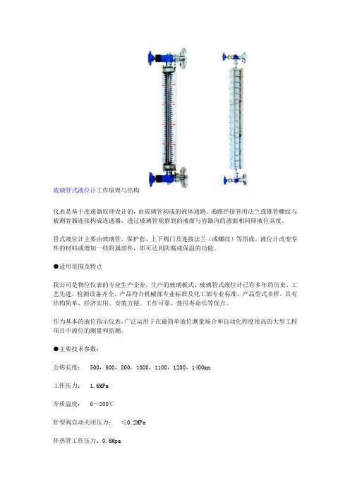
玻璃管式液位计工作原理与结构仪表是基于连通器原理设计的,由玻璃管构成的液体通路。
通路经接管用法兰或锥管螺纹与被测容器连接构成连通器,透过玻璃管观察到的液面与容器内的液面相同即液位高度。
管式液位计主要由玻璃管、保护套、上下阀门及连接法兰(或螺纹)等组成。
液位计改变零件的材料或增加一些附属部件,即可达到防腐或保温的功能。
●适用范围及特点我公司是物位仪表的专业生产企业,生产的玻璃板式、玻璃管式液位计已有多年的历史、工艺先进,检测设备齐全,产品符合机械部专业标准及化工部专业标准,产品型式多样。
具有结构简单、经济实用、安装方便、工作可靠、使用寿命长等优点。
作为基本的液位指示仪表,广泛运用于在最简单液位测量场合和自动化程度很高的大型工程项目中液位的测量和监测。
●主要技术参数:公称长度:500,600,800,1000,1100,1200,1400mm工作压力: 1.6MPa介质温度:0~200℃针型阀自动关闭压力:≤0.2MPa伴热管工作压力:0.6MpaUHZ-10系列磁翻板液位计工作原理UHZ-10系列磁翻板液位计是北京金德创业测控技术有限公司在引进、改进国外同类液位计,结合本公司此类液位计长期销售中取得的经验的基础上,依照化工工业部标准HG/T21584-95开发、研制出的最新产品。
为保证产品的可靠性和技术上的优势,该仪表的所有关键部位均采用优质原材料或进口元器件。
该产品完全可代替国外同一类型产品,性能可靠、安全、实用,可适应对高温、高压、腐蚀性液位的测量。
工作原理金德公司UHZ-10系列磁翻板液位计可以视为压力容器的一部分。
以UHZ-10系列侧装式磁翻板液位计为例,液位计与容器通过侧法兰相连接,这样液位计中的变化实际与容器内液位变化是相一致的。
液位计腔内的柱状浮子与液位计外部的磁翻板和一关实际为一组磁性系统。
柱状浮子通过磁场影响翻板内的翻珠和开关内的磁性元件,从而将液位传递出去。
磁翻板是显示液位的部分。
外测液位计与外测液位开关技术规格详解

西安定华外贴液位计技术规格详解一、ELL-FI外贴液位计(一)、规格1、ELL-FI-A标准型(经典型)用于30m量程内各种罐型的常规工况。
可内调或外调阀值,不能调频。
2、ELL-FI-B增强型(极品型)不仅可用于30m量程内各种罐型的常规工况,而且可用于30m量程内各种罐型的严苛工况。
阀值、频率可根据现场工况外调。
3、ELL-FI-P紧凑型(经济型)用于16m量程内卧罐和立罐。
可内调阀值,不能调频。
4、ELL-FI-V车载型(抗震性)适用于6m量程内油罐车、化学液体运输车辆。
可内调阀值,不能调频。
(二)、测量精度1、仪表的测量精度通常以最大允许的绝对误差或相对误差表示。
以绝对误差表示精度等级,例如液位计精度等级1mm、5mm、10mm;以相对误差表示精度等级,例如液位计精度等级0.5%F.S.、0.2% F.S.、0.1% F.S.F.S.=Full Scale 表示额定检测距离的范围。
F.S. 表示满量程。
%F.S是指传感器的指标相对于传感器的满量程误差的百分数2、绝对误差和相对误差的换算相对误差=绝对误差/满量程×%3、几个定义绝对误差:一个量的观测值或计算值与其真实值(真值)之差。
误差是不可避免的,只能减小。
真值:是一个变量本身所具有的真实值,它是一个理想的概念,一般是无法得到的。
所以在计算误差时,一般用约定真值或相对真值来代替。
约定真值也称规定真值,是一个接近真值的值,它与真值之差可忽略不计。
绝对误差并不能完全表示近似值的好坏程度,例如:x=10±1,y=1000±5,哪一个精度高呢?看上去x的绝对误差限比y的绝对误差限小,似乎x的精度高,其实不然。
绝对误差计算公式:测量值-真实。
绝对误差有正负之分的。
相对误差:指的是测量所造成的绝对误差与被测量〔约定〕真值之比。
乘以100%所得的数值,以百分数表示。
一般来说,相对误差更能反映测量的可信程度。
相对误差等于测量值与真值差的绝对值除以真值,再乘以100%。
液位计的特点及应用介绍

液位计的特点及应用介绍液位计是一种用于测量液体表面高度或液位深度的工具。
根据测量原理的不同,液位计被分为机械液位计和电子液位计两种型号。
在不同的应用场景中,液位计还有不同的特点和优势。
机械液位计的特点机械液位计是利用浮子、指针、刻度盘或螺旋形刻度来显示液位高度的工具。
它具有以下特点:1.简单可靠:机械液位计的结构相对简单,不需要电池或电源,也不容易受到外部干扰,因此其可靠性很高。
2.易于安装:机械液位计的安装相对较为简单,只需安装在液位箱顶部即可。
3.可视化显示:机械液位计通过指针、刻度盘等可视化的方式,直接显示液位高度,便于操作人员观察和控制工艺流程。
4.耐腐蚀:机械液位计的浮子、管道等部件可采用不锈钢或耐腐蚀材料制作,可以避免因液体腐蚀而造成的故障。
电子液位计的特点电子液位计是利用电子信号传感技术来测量液位高度的工具。
它具有以下特点:1.高精度:电子液位计采用数字化测量技术,能够实现较高的测量精度,更利于进行自动化控制。
2.多功能:电子液位计可以通过外部系统与PLC或DCS控制器联动,实现自动化控制、远程监测等多种功能。
3.显示直观:电子液位计通过LED数码管、液晶显示屏等方式直观显示液位高度,便于观察。
4.精密校准:电子液位计可以进行更加精确的校准,提高了测量数据的准确性,有助于产品质量管理。
液位计的应用液位计是工业生产中不可或缺的仪器。
它在各种工业领域中都有广泛的应用,包括:1.石化、化工工业:可以用于监测、控制化工反应釜的液位,确保生产过程的顺利进行。
2.食品、饮料业:可以用于测量牛奶、果汁等液体罐头的液位,确保产品质量。
3.能源、环保工业:可以用于液压油箱、油池等液体容器的液位监测,确保设备正常运行。
4.火电、核电工业:可以用于锅炉、反应堆等液体系统的液位监控。
综上所述,液位计具有测量精度高、自动化程度高、可视化直观等优点,能够广泛应用于各种工业领域中,对其进行科学使用和管理十分必要。
RK23191和RK23191-01水分检测探头(海洋类型认证,适用于所有船舶)-Parker Ha

Contact Information:Parker Hannifin Corporation Racor Division P .O. Box 32083400 Finch Road Modesto, CA 95353phone 800 344 3286209 521 7860fax 209 529 3278****************/racorclassed vessels and may be acceptable under other International Association of Classification Societies (IACS) members.In use, when the collected water level within the Racor filter bowl/sump rises to the height of the probe tip, a Racor Water Detection Amplifier (ordered separately) willdetect the change in electrical resistance (ohms) of the fluid.When this happens, the Amplifier will alert the operator that draining of the Racor is required.This WIF may be used with all Racor Water Detection Amplifiers and the following Racor filter models: Turbine Series, Spin-on Series, DFBO, FBO and 800 Series.Product Features:• A BS Marine Type Approved, Cert. #11-HS800012-PDA.• UL Marine Listed, 168Y.• M eets requirements of ISO19921 fire resistance test.• 303 Stainless Steel and Ceramic construction.• S AEJ1926 Straight thread with O-ring sealing design.• F luorocarbon (FKM) O-ring for durable service life.• D etachable Packard GT-Series 2-terminal connector.• 36” long 18AWG yellow/black wires (no polarity) (RK23191).• 8" long 18AWG yellow/black wires (no polarity) harness with Deutsch DT04-3P connector (RH23191-01).Mounting InformationCeramic InsulatorProbeTip0.95 HEX1/2"-20 UNF ThreadsStainless SteelConnector(8.1 cm)Installation Guidelines1. T he WIF is installed in TurbineSeries or Spin-on Seriescontaminant collection bowls byremoving the existing probe portplug. This plug will have 1/2"-20straight threads and an o-ring willbe present.2. C lean the sealing gland of theport with a clean cloth to removeany debris.3. A pply silicone grease or cleandiesel fuel to the WIF O-ring.4. I nstall the WIF into the port andtighten to 90 inch pounds (10newton/m) max.5. R efer to the instructions providedwith the Racor Water DetectionAmplifier to complete the wiringprocedure.6. E nsure the final connection of theharness to the WIF connectorhousing is made prior to testingthe system.All products manufactured or distributed by Racor are subject to the following, and only the following, LIMITED EXPRESS WARRANTIES, and no others: For a period of one (1) year from and after the date of purchase of a new Racor product, Racor warrants and guarantees only to the original purchaser-user that such a product shall be free from defects of materials and workmanship in the manufacturing process. The warranty period for pumps and motors is specifically limited to ninety (90) days from date of purchase. A product claimed to be defective must be returned to the place of purchase. Racor, at its sole option, shall replace the defective product with a comparable new product or repair the defective product. This express warranty shall be inapplicable to any product not properly installed and properly used by the purchaser-useror to any product damaged or impaired by external forces. THIS IS THE EXTENT OF WARRANTIES AVAILABLEON THIS PRODUCT. RACOR SHALL HAVE NO LIABILITY WHATSOEVER FOR CONSEQUENTIAL DAMAGES FLOWING FROM THE USE OF ANY DEFECTIVE PRODUCT OR BY REASON OF THEFAILURE OF ANY PRODUCT.RACOR SPECIFICALLYDISAVOWS ALL OTHERWARRANTIES, EXPRESSOR IMPLIED INCLUDING,WITHOUT LIMITATION, ALLWARRANTIES OF FITNESSFOR A PARTICULAR PURPOSE(EXCEPT FOR THOSE WHICHAPPLY TO PRODUCT ORPART THEREOF THAT ISUSED OR BOUGHT FOR USEPRIMARILY FOR PERSONAL,FAMILY, OR HOUSEHOLDPURPOSES), WARRANTIES OFDESCRIPTION, WARRANTIESOF MERCHANTABILITY, TRADEUSAGE OR WARRANTIES ORTRADE USAGE.WarningFailure or improper selection orimproper use of the productsand/or systems describedherein or related itemscan cause death, personalinjury and property damage.This document and otherinformation from Parker HannifinCorporation, its subsidiariesand authorized distributorsprovide product and/or systemoptions for further investigationby users having technicalexpertise. It is important thatyou analyze all aspects of yourapplication and review theinformation concerning theproduct or system in the currentproduct catalog. Due to thevariety of operating conditionsand applications for theseproducts or systems, the user,through its own analysis andtesting, is solely responsiblefor making the final selection ofthe products and systems andassuring that all performance,safety and warning requirementsof the applications are met.The products described herein,including with limitation,product features, specifications,designs, availability and pricing,are subject to change by ParkerHannifin Corporation and itssubsidiaries at any time withoutnotice.The following statement isrequired pursuant to proposition65, applicable in the State ofCalifornia: ‘This product maycontain a chemical known tothe State of California to causecancer or reproductive toxicity’.Limited Warranties StatementNovember 2011© Parker Hannifin Corporation。
图科电子TK-LW外贴式超声波液位计使用说明书

外贴式超声波液位计 使用说明书
济南图科电子有限公司
电话:0531-88687081
1
传真:0531-88687083
网址:
济南图科电子有限公司
1.产品概述
外贴式超声波液位计
TK-LW 型外贴式超声波液位计,是我公司研发的一项新技术、新产品,液 位测量采用了传感器外贴、与被测液体非接触式测量方式,实现真正意义上 的完全隔离测量。外贴式超声波液位计,可在罐外连续测量液位,对罐体不 开孔、不动火、实现不停产安装。特别适合密闭容器内的各种有毒物质﹑强 酸﹑强碱及各种纯净液体的液位进行精确测量。仪表采用防爆设计,在防爆 场合得到广泛应用。
功能名和功能值之间由“确定”键隔开。
功能名一般由3为数字组成。
格式:“功能名”+“确定”+“功能值”+“确定”
9.2 进入或退出功能码设置
在正常液位计的工作状态下,手握调试器对着显示屏上的接收器连续
两次按下“确定”键后,液位计会在显示屏上显示提示信息“请输入
功能码!”,此时,用户方可输入功能码。如果功能码输入正确,按
12
传真:0531-88687083
网址:
济南图科电子有限公司
易损件(橡胶密封圈)应定期更换。
单位:mm
矩形密封圈
型圈A
型圈B
型圈C
14 防爆型液位计使外用置注式超意声事波项液位计(隔爆型)易损件图
液位计引出线需分线或再接线时,必须使用防爆分(接)线盒(取得 防爆合格证、接线盒上有Ex标志)。当接线盒存在多余出口时,必须 使用与接线盒防爆型式一致的封堵件予以密封,以保证其防爆性能;
94功能码表功能区功能码名称举例备注出厂参数区开头测量探头参数暂不开放开头校准探头参数暂不开放用户参数区201声速2011485代表确定键202量程2023000203迁移量2030204盲区204300208校准距离208200209校准周期209600210探头高度2101特殊参数区802硬件诊断802任何数字用户慎用804图形界面8041查看波形图特殊参数区901智能修复901任何数字出现故障时使用902复位902任何数字重启液位计济南图科电子有限公司电话
- 1、下载文档前请自行甄别文档内容的完整性,平台不提供额外的编辑、内容补充、找答案等附加服务。
- 2、"仅部分预览"的文档,不可在线预览部分如存在完整性等问题,可反馈申请退款(可完整预览的文档不适用该条件!)。
- 3、如文档侵犯您的权益,请联系客服反馈,我们会尽快为您处理(人工客服工作时间:9:00-18:30)。
正品Parker派克液位计FL69121特征
Parker派克液位计项目信息
Parker派克液位计两用液位/温度计
Parker派克液位/温度计采纳通用固定装置,专为前部或后部油箱安装而设计。
这些量规有三种尺寸,每种尺寸都有双孔安装,中心位置分别为76mm、127mm和254mm。
定位仪表后,只需拧紧螺栓即可供给安全密封。
方形截面密封件将泄漏的可能性降,而两点安装系统除去了储罐变形的问题。
正品Parker派克液位计优势供货:Parker派克液位/温度计采纳一体式高可见度透镜,以加添安全性。
镜片采纳防碎透亮聚酰胺模制而成,可确保精准、清楚的油位和温度指示。
原装正品Parker 派克液位计到货周期快;Parker派克供给各种储液罐设备和油箱配件,旨在确保液压系统的性能和牢靠性,包括两用流体/温度计、电容式液位开关和浮球液位开关。
Parker派克液位计货期短正品销售:储罐附件–Parker派克液位计液位/温度计、浮子和电容式液位开关|#FL69121
派克供给各种储液罐设备和油箱配件,旨在确保液压系统的性能和牢靠性,包括两用流体/温度计、电容式液位开关和浮球液位开关。
Parker派克液位计和开关是一系列易于安装并具成本效益的油箱液位指示器。
Parker派克液位/温度表
通用固定设计用于前后油箱安装。
液位/温度计供给三种尺寸,每个尺寸均具有2个安装孔,中心安装距离分别是76mm,127mm和254mm
高可见度观测镜是一体式设计,加添了安全性,采纳防碎透亮聚酰胺成型。
一体式设计,高可见度视角镜片,加添安全性,防碎,透亮尼龙成型。
Parker派克浮子和液位开关;原装正品Parker派克液位计到货周期快;正品Parker派克液位计优势供货
具有成本效益的油箱解决方案具有很多应用。
一系列高品质,可调整的浮子开关,采纳簧片开关牢靠设计。
有3个长度:500mm,1000mm和1500mm。
一个电容式液位开关,用于检测油箱内低于工作液位的流体损失。
安装简单,无移动部件。
Parker派克液位计
长度:76毫米(3”)
端口连接类型:M10
密封材料:丁腈
选件:包括.温度计
品牌:派克
分部:液压与工业过程过滤事业部欧洲、中东和非洲
行业:农业、建筑、石油和天然气、海洋、采矿、林业
应用:甲板和移动式起重机、消防设备、货运代理、液压机、船用转向装置、动力单元、废物管理、自卸和叉车、挖掘机、收割机、垃圾打包机、正面吊、轮式装载机、钻井设备、工业动力装置。
技术:液压、过滤
产品类型:液压过滤器配件
产品序列:液位/温度计
与流体类型共同使用:液压油
工作压力:1bar
工作温度:30°C至+90°C
壳体材料:聚酰胺/尼龙/聚苯乙烯
Parker派克液位计特征:
供给M10或M12螺栓螺纹
Parker派克温度计刻度范围:30至+90°C(86至+194°F)
工作温度:30至+90°C(22至+194°F)
可调浮子液位开关–FL系列
并安装设备。
