latch up测试标准
ESD与latchup测试介绍
1、ESD模型分类 2、HBM和MM测试方法标准 3、 CDM模型和测试方法标准 4、拴锁测试 5、 I-V测试 6、标准介绍
1、ESD模型分类
因ESD产生的原因及其对集成电路放电的方式不同, 经过统计,ESD放电模型分下列四类:
(1) 人体放电模式 (Human-Body Model, HBM) (2) 机器放电模式 (Machine Model, MM) (3) 组件充电模式 (Charged-Device Model, CDM) (4) 电场感应模式 (Field-Induced Model, FIM) 另外还有两个测试模型: (5)对于系统级产品测试的IEC电子枪空气放电模式 (6)对于研究设计用的TLP模型
人体放电模式 (Human-Body Model, HBM)
人体放电模式(HBM)的ESD是指因人体在地上走动磨擦或其它因素在人体上 已累积了静电,当此人去碰触到IC时,人体上的静电便会经由IC的脚(pin)而 进入IC内,再经由IC放电到地去,如图2.1-1(a)所示。此放电的过程会在短 到几百毫微秒(ns)的时 间内产生数安培的瞬间放电电流,此电流会把IC内的 组件 给烧毁。 不同HBM静电电压相对产生的瞬间放电电流与时间的关系 显 示于图2.1-1(b)。对一般商用IC的2-KV ESD放电电压而言,其瞬间放电电流 的尖峰值大约是1.33 安培。
有关FIM的放电模式早在双载子(bipolar)晶体管时代 就已被发现,现今已有工业测试标准。
国际电子工业标准(EIA/JEDEC STANDARD) 中亦 有此电场感应模式订定测试规范 (JESD22-C101) 。
HBM, MM与CDM模型参数比较
2KV HBM, 200V MM, 与1KV CDM的放电电流比较,其中1KV CDM的放电电流 在不到1ns的时间内,便已冲到约15安培的尖峰值,但其放电的总时段约在10ns的 时间内便结束。此种放电现象更易造成集成电路的损伤。
LATCH UP 测试分析
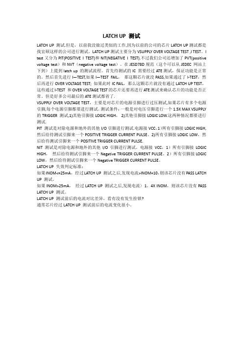
LATCH UP 测试LATCH UP 测试.但是,以前我没做过类似的工作,因为以前的公司的芯片LATCH UP测试都是找宜硕这样的公司进行测试。
LATCH UP测试主要分为VSUPPLY OVER VOLTAGE TEST ,I TEST。
I test又分为PIT(POSITIVE I TEST)和NIT(NEGATIVE I TEST).不过我们公司还增加了PVT(positive voltage test)和NVT(negative voltage test)。
在JESD78D规范(这个可以从JEDEC 网站上下到)上提到latch up 的测试流程。
首先待测试的IC 需要经过ATE测试,保证功能是正常的。
然后首先进行I—TEST,如果I—TEST FAIL,那这颗芯片就没PASS,如果通过了I-TEST,然后再进行OVER VOLTAGE TEST; 如果此时IC FAIL,那么这颗芯片就没有通过LATCH UP TEST,这些通过I-TEST 和OVER VOLTAGE TEST的芯片还要再进行ATE测试来确认芯片的功能是否正常。
但是好多公司最后的ATE测试都省了.VSUPPLY OVER VOLTAGE TEST,主要是对芯片的电源引脚进行过压测试,如果芯片有多个电源引脚,每个电源引脚都要进行测试。
测试条件:一般是对电压引脚进行一个1.5X MAX VSUPPLY 的TRIGGER 测试,1)其他引脚接LOGIC HIGH,2)其他引脚接LOGIC LOW.这两种情况都要进行测试.PIT 测试是对除电源和地外的其他I/O引脚进行测试.电源接VCC,1)所有引脚接LOGIC HIGH, 然后给待测试引脚来一个POSITIVE TRIGGER CURRENT PULSE。
2)所有引脚接LOGIC LOW,然后给待测试引脚来一个POSITIVE TRIGGER CURRENT PULSE.NIT 测试是对除电源和地外的其他I/O引脚进行测试。
ESD与latchup测试介绍解读

HBM测试方法及标准 1.ANSI-STM5.1-2001 JESD22-A114D -2005 AEC-Q100-002D -2003 2.该标准用于明确HBM模式下的ESD电压敏感度的 测试、评价以及分级过程 3.整个测试过程繁琐,尤其对仪器及脉冲波形的校 验工作,但非常必要 4. ESD测试中,器件不在工作状态
FIM模式的静电放电发生是因电场感应而起的。当 IC因输送带或其它因素而经过一电场时,其相对 极性的电荷可能会自一些IC脚而排放掉,等IC通 过电场之后,IC本身便累积了静电荷,此静电荷 会以类似CDM的模式放电出来。
有关FIM的放电模式早在双载子(bipolar)晶体管时代 就已被发现,现今已有工业测试标准。 国际电子工业标准(EIA/JEDEC STANDARD) 中亦 有此电场感应模式订定测试规范 (JESD22-C101) 。
ESD模型及有关测试
1、ESD模型分类 2、HBM和MM测试方法标准 3、 CDM模型和测试方法标准 4、拴锁测试 5、 I-V测试 6、标准介绍
1、ESD模型分类
因ESD产生的原因及其对集成电路放电的方式不同, 经过统计,ESD放电模型分下列四类: (1) 人体放电模式 (Human-Body Model, HBM) (2) 机器放电模式 (Machine Model, MM) (3) 组件充电模式 (Charged-Device Model, CDM) (4) 电场感应模式 (Field-Induced Model, FIM) 另外还有两个测试模型: (5)对于系统级产品测试的IEC电子枪空气放电模式 (6)对于研究设计用的TLP模型
HBM/MM测量方法
如果每次调升的ESD测试电压调幅太小,则测试到IC脚损坏要 经过多次的ESD放电,增长测试时间; 若每次调升的ESD测试电 压太大,则难以较精确测出该IC脚的ESD耐压能力。 规定: 正负极性均要测试 从低压测到高压,起始电压为70%的平均ESD failure threshold (VESD) 步进当小于1000V时步进50V(100V),大于1000V时步进 100V(250V, 500V) 可以是一个管脚步进测量或者所有管脚扫描测量
Thermo Scientific MK.4 ESD和Latch-Up测试系统中文名说明书
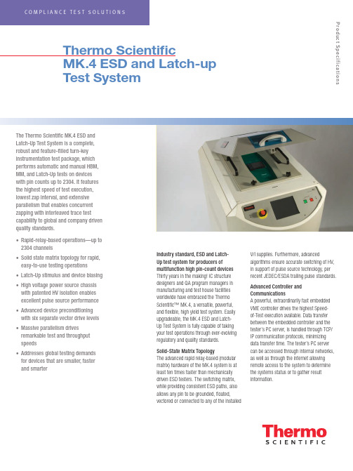
The Thermo Scientific MK.4 ESD and Latch-Up Test System is a complete,robust and feature-filled turn-key instrumentation test package, which performs automatic and manual HBM, MM, and Latch-Up tests on devices with pin counts up to 2304. It features the highest speed of test execution, lowest zap interval, and extensive parallelism that enables concurrent zapping with interleaved trace test capability to global and company driven quality standards.• Rapid-relay-based operations—up to 2304 channels• Solid state matrix topology for rapid, easy-to-use testing operations • Latch-Up stimulus and device biasing • High voltage power source chassis with patented HV isolation enables excellent pulse source performance • Advanced device preconditioning with six separate vector drive levels • Massive parallelism drives remarkable test and throughput speeds• Addresses global testing demands for devices that are smaller, faster and smarterThermo ScientificMK.4 ESD and Latch-up Test SystemIndustry standard, ESD and Latch-Up test system for producers ofmultifunction high pin-count devices Thirty years in the making! IC structure designers and QA program managers in manufacturing and test house facilities worldwide have embraced the Thermo Scientific™ MK.4, a versatile, powerful, and flexible, high yield test system. Easily upgradeable, the MK.4 ESD and Latch-Up Test System is fully capable of taking your test operations through ever-evolving regulatory and quality standards.Solid-State Matrix TopologyThe advanced rapid relay-based (modular matrix) hardware of the MK.4 system is at least ten times faster than mechanically driven ESD testers. The switching matrix, while providing consistent ESD paths, also allows any pin to be grounded, floated,vectored or connected to any of the installedV/I supplies. Furthermore, advancedalgorithms ensure accurate switching of HV, in support of pulse source technology, per recent JEDEC/ESDA trailing pulse standards.Advanced Controller and CommunicationsA powerful, extraordinarily fast embedded VME controller drives the highest Speed- of-Test execution available. Data transfer between the embedded controller and the tester’s PC server, is handled through TCP/IP communication protocols, minimizing data transfer time. The tester’s PC server can be accessed through internal networks, as well as through the internet allowing remote access to the system to determine the systems status or to gather result information.Product SpecificationsLatch-Up Stimulus and Device Biasing The MK.4 can be equipped with up to eight 100 V four-quadrant Voltage and Current (V/I) power supplies. Each V/I supply has a wide dynamic range enabling it to force and measure very low voltage at high current levels from 100 mV/10 A to 100 V/1 A. The system’s power supply matrix can deliver up to a total of 18A of current, which is distributed between the installed supplies. These supplies are able to provide a fast and versatile means of making DC parametric and leakage measurements as well as providing latch-up pulses, while offering total control and protection of the DUT.Advanced Device PreconditioningThe MK.4 system provides the most advanced device preconditioning capability available. The DUT can be vectored with complex vector patterns, providing excellent control over the device. Each pin can be driven using one of the 6 different vector supplies. The patterns can be up to 256k deep, running at clock speeds of up to 10 MHz. Device conditioning is easily verified, using the read back compare capability available on every pin.Thermo Scientific MK.4 Scimitar™Software Makes Programming Easy, while Providing Unsurpassed Programming FlexibilityThe MK.4 Windows®-based Scimitar operating software empowers users with the flexibility to easily set-up tests based on industry standards or company driven requirements.Device test plans can be created by importing existing text based device files, on the testers PC server or off-line from a satellite PC containing the application. The software also provides the capabilities to import test plans and device files from previous Thermo Scientific test systems.Test vectors from your functional testers can also be imported into the application. And of course, the vector application allows manual creation and debug of vector files.Device test plans and results are stored in an XML data base, providing unsurpassed results handling, sorting and data mining capabilities.Parallelism Drives Remarkable Test Throughput SpeedsThe MK.4 software enables ESD testing of up to twelve devices at one time using the multisite pulse source design.Embedded VME power supplies eliminate any communication delays that would be seen by using stand alone supplies. The embedded parametric (curve tracing) supply also provides fast, accurate curve tracing data to help you analyze your devices performance.The systems curve tracer can also be used as a failure analysis tool by allowing the comparison of stored, known good results, versus results from a new test sample or samples.Ready for Today’s Component Reliability Demands and Anticipating Those to Come ESD and Latch-Up testing of electronic and electrical goods can be very expensive aspects of the design and manufacturing process. This is especially true as market demands for products that are smaller, faster and smarter become the standard rather than the exception. The Thermo Scientific MK.4 leverages the technology and know- how gained over three decades of test system experience, as well as our in-depth participation and contributions to global regulatory bodies governing these changes, enabling today’s products to meet both global and industry-driven quality standards.The real key to our customers’ success is in anticipating what’s next. And to ensure that our customers possess the ability to evolve quickly to meet all change factors with efficiency and cost effectiveness.As such, the strategically-designed, field upgradeable architecture of the MK.4 system ensures a substantial return on investment over a very considerable test system lifecycle, as well as better short- and long-term qualityand ESD and Latch-Up test economies.Custom fixtures include universal package adaptors to enable the industry’s lowest cost-in-service high pin count device fixturing yetdevised. (2304-pin, Universal 1-mm pitch BGA package adaptor shown.)100W V/I Performance Thermo Scientific MK.4: eight-V/I configuration. Powerful V/Is can deliver a total of 800 W to the DUT, enabling complex testing of all advanced high power processors on your product roadmap.Solid state matrix topology for rapid, easy-to-use testing operations. Design ensures waveform integrity and reproducibility.General SpecificationsHuman Body Model (HBM) per ESDA/JEDEC JS-001-2014, MIL-STD 883E, and AEC Q100-002 25 V to 8 kV in steps of 1 V Test to multiple industry standards in one integrated system; no changing or alignment of pulse sources.Wizard-like prompts on multi-step user actions MachineModel (MM) per ESDA STM5.2, JEDEC/JESD22-A115, andAEC Q100-003, 25 V to 1.5 kV in steps of 1 VIntegrated pulse sources allow fast multi-site test execution.Latch-up testing per JEDEC/JESD 78 test pin and AECQ100-004Includes preconditioning, state read-back and full control of each.Rapid Relay-based operations at least 10 times faster thanrobotic-driven testersSuper fast test speeds.Test devices up to 2304 pins Systems available configured as 1152, 1728 or 2304 pins.Waveform network: Two, 12 site HBM (100 pF/1500Ω)and MM (200 pF/0Ω) pulse sources address up to 12devices simultaneouslyPatented design ensures waveform compliance for generations to come.Multiple device selection When multiple devices are present; graphical display indicates the devices selectedfor test; progress indicator displays the current device under test (DUT), along withtest status information.Unsurpassed software architecture Flexible programming, easy to use automated test setups, TCP/IP communication. Enables use of device set-up information Increased efficiency and accuracy from other test equipment, as well as deviceinformation import.Event trigger output Manages setup analysis with customized scope trigger capabilities.High voltage power supply chassis Modular chassis with patented HV isolation enables excellent pulse sourceperformance.Power supply sequencing Provides additional flexibility to meet more demanding test needs of integratedsystem-on-chip (SOC) flexibility.Manages ancillary test equipment through Plug-n feature allows the user to control external devices, such as scopes or heatstreams or other devices the Scimitar Plug-ins feature as required for automatedtesting.Pin drivers for use during Latch-Up testing Vector input/export capability from standard tester platforms and parametricmeasurements.256k vectors per pin with read-back Full real-time bandwidth behind each of the matrix pins.Six independent vector voltage levels Test complex I/O and Multi-Core products with ease.Up to 10MHz vector rate (programmable) Quickly and accurately set the device into the desired state for testing from an internalclock.Comprehensive engineering vector debug. Debug difficult part vectoring setups with flexibility.Up to eight separate V/I supplies (1 stimulus and 7 bias supplies) capability through the V/I matrix High accuracy DUT power, curve tracing, and Latch-up stimulus available; design also provides high current.Low resolution/high accuracy parametric measurements, using an embedded Keithley PSU With the optional Keithley PSU feature (replaces one V/I, nA measurements are achievable, allowing supply bus resistance measurement analysis to be performed.Multiple self-test diagnostic routines Ensures system integrity throughout the entire relay matrix, right up to the test socket Test reports: pre-stress, pre-fail (ESD) and post-fail data,as well as full curve trace and specific data pointmeasurementsData can be exported for statistical evaluation & presentation.Individual pin parametrics Allows the user to define V/I levels, compliance ranges, and curve trace parametersfor each pin individually.Enhanced data set features Report all data gathered for off-line reduction and analysis; core test data is readilyavailable; all data is stored in an easy-to-manipulate standard XML file structure. Interlocked safety cover Ensures no user access during test. All potentially lethal voltages are automaticallyterminated when cover is opened. Safety cover window can be easily modified toaccept 3rd party thermal heads.Dimensions60 cm (23.5 in) W x 99 cm (39 in) D x 127 cm (50 in) H© 2016 Thermo Fisher Scientific Inc. All rights reserved. Windows is a registered trademark of Microsoft Corporation in the United States and/or other countries. All other trademarks are the property of Thermo Fisher Scientific and its subsidiaries. Results may vary under different operating conditions. Specifications, terms and pricing are subject to change. Not all products are available in all countries. Please consult your local sales representative for details.Africa-Other +27 11 570 1840 Australia +61 2 8844 9500 Austria +43 1 333 50 34 0 Belgium +32 53 73 42 41 Canada +1 800 530 8447 China +86 10 8419 3588 Denmark +45 70 23 62 60 Europe-Other +43 1 333 50 34 0Finland /Norway/Sweden+46 8 556 468 00France +33 1 60 92 48 00Germany +49 6103 408 1014India +91 22 6742 9434Italy +39 02 950 591Japan +81 45 453 9100Latin America +1 608 276 5659Middle East +43 1 333 50 34 0Netherlands +31 76 579 55 55South Africa +27 11 570 1840Spain +34 914 845 965Switzerland +41 61 716 77 00UK +44 1442 233555USA +1 800 532 4752Thermo Fisher Scientific,San Jose, CA USA is ISO Certified. CTS.05102016Product SpecificationsScimitar Software FeaturesSummary Panel with easy navigation among device componentsWizard-like prompts on multi-step user actionsControl of external devices through the use of Scimitar’s user programmable Plug-in capabilities, in addition to the Event Trigger Outputs, which provide TTL control signals for external devices, such as power supplies or for triggering oscilloscopesFlexible parametric tests that are defined and placed at an arbitrary position within the executable test plan.Comprehensive results viewer that provides:• ESD and Static Latch-up data viewing capabilities• Curves viewer with zooming capabilities and the ability to add user comments• Data filtering on the following criteria – failed pins, failed results, final stress levels• A complete set or subset of results using user defined parameters• Sorting in ascending or descending order by various column criteriaTree-like logical view of the tests and test plans.Flexible data storage that provides the ability for the end-user to query the dataSeamless support of existing ZapMaster, MK.2, MK.4, and Paragon test plansCurve tracing with curve-to-curve and relative spot-to-spot comparisonOff-line curve analyzing, including third-party generated waveformsCanned JESD78A test (static latch-up only) that can be defined automaticallyPause/Resume test capabilitiesIntermediate results viewingAutomated waveform capture capability and analysis using the embedded EvaluWave software feature。
latch up考核标准
latchup考核标准一、考核目的LATCHUP考核旨在评估员工在工作中对LatchUp知识的掌握程度和应用能力,以确保员工能够胜任相关岗位的工作,提高工作效率和质量。
二、考核范围tchUp基础知识:包括LatchUp定义、基本原理、特点等。
tchUp应用技能:包括LatchUp在电路设计、调试、测试等方面的应用技能。
3.实际案例分析:根据实际工作场景,对LatchUp应用案例进行分析和解决。
三、考核标准1.知识掌握程度:a.正确回答LatchUp基础知识试题的比例;b.能够运用LatchUp基础知识进行电路设计,说明其原理和应用;c.能够运用LatchUp基础知识解决实际工作中的问题,提供合理有效的解决方案。
2.技能应用能力:a.完成LatchUp电路调试的时间和成功率;b.能够在团队中有效协作,与其他成员共同完成LatchUp电路的设计和调试;c.能够根据实际需求,选择合适的LatchUp技术进行电路设计。
3.案例分析能力:a.对实际工作场景中的LatchUp应用案例分析的准确性和全面性;b.能够提出有效的解决方案,并得到实际验证;c.能够总结经验教训,为今后的工作提供参考。
四、考核方式1.笔试:通过试卷形式,测试员工对LatchUp基础知识和技能的掌握程度。
2.实践操作:员工在实际工作中应用LatchUp技术进行电路设计、调试和测试,展示技能应用能力。
3.案例分析:员工对实际工作场景中的LatchUp应用案例进行分析和解决,展示案例分析能力。
五、考核周期和评分标准1.考核周期:每季度进行一次LATCHUP考核,以确保员工能够及时了解自己的不足之处并加以改进。
2.评分标准:根据考核结果,员工将获得相应的分数和评级。
分数越高,评级越高,说明员工在LATCHUP方面的表现越好。
具体的评分标准如下:a.优秀(90分以上):表现出色,能够熟练运用LatchUp技术进行电路设计、调试和测试,同时具备较强的案例分析能力;b.良好(80-89分):表现良好,具备一定的LatchUp技能应用能力和案例分析能力,但仍需继续提高;c.一般(70-79分):需要加强学习,具备一定的LatchUp基础知识,能够完成基本的电路设计和调试任务;d.待提高(70分以下):需要加强学习和实践,尽快掌握LatchUp技术。
latch_up分析
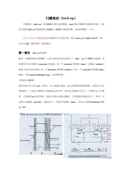
闩锁效应(latch up)闩锁效应(latch up)是CMOS必须注意的现象,latch我认为解释为回路更合适,大家以后看到latch up就联想到在NMOS与PMOS里面的回路,其实你就懂了一半了.为什么它这么重要因为它会导致整个芯片的失效,所以latch up是QUAL测试的一种,并且与ESD(静电防护)紧密相关。
第一部分latch up的原理我用一句最简单的话来概括,大家只要记住这句话就行了:latch-up是PNPN的连接,本质是两个寄生双载子transisitor的连接,每一个transistor的基极(base)与集极(collector)相连,也可以反过来说,每一个transistor的集极(collector)与另一个transistor的基极(base)相连,形成positive feedback loop(正回馈回路),下面我分别解释。
我们先复习什么是npn,如图1,在n端加正偏压,np之间的势垒就会降低,n端电子为主要载流子,于是电子就很开心地跑到p,其中有一部分电子跑得太开心了,中间的p又不够厚,于是就到pn的交界处,这时右边的n端是逆偏压,于是就很容易就过去了。
所以,左边的n为射极(emmiter,发射电子),中间P为基极(base),右边n为集极(collector,收集电子嘛)理解了npn,那么pnp就好办,如图2。
图2清楚的表示了latch up的回路。
左边是npn,右边是pnp图3是电路示意图。
大家可以看出,P-sub既是npn的基极,又是pnp的集极;n-well既是既是pnp的基极,又是npn的集极,所以说,每一个transistor的集极(collector)与另一个transistor的基极(base)相连。
那么电流怎么走呢比如在P+加5V-->电洞被从P+推到N well-->越过n well再到p sub-->这个时候,大家注意,电洞有两条路可走,一是跑到NMOS的N+,二是跑到旁边的Nwell,nwell比n+深,当然更好去,所以电洞又回去了。
latch up标准
latch up标准Latch-up是一个电路问题,可能会导致芯片失效,因此在芯片的可靠性测试中是一个很重要的问题。
带有负反馈的集成电路在不适当的使用下可能引起电路中的正反馈回路,使其失去控制,这种情况称为Latch-up。
Latch-up出现在芯片设计不合理或者工艺制备工艺不合理的情况下,Latch-up会导致芯片销毁。
因此,研究Latch-up现象并提高集成电路的可靠性,是集成电路工业和学术界都十分关注的问题。
Latch-up的现象和成因Latch-up的发生表现为电路的电压和电流异常增大,导致芯片工作不正常,性能下降,甚至烧毁芯片。
Latch-up的形成主要是由于CMOS工艺兼容性等方面的原因,导致PNP及NPN晶体管集成电路中的短路问题。
CMOS技术在很大程度上取代了传统的NMOS技术,CMOS电路中经常使用P-型场效应晶体管,使得Latch-up问题变得更加复杂。
CMOS集成电路中,源漏极之间有一个隔离电阻,若该电阻失效或范围不够大,定向之间的反馈回路就会让某一个晶体管变成双极晶体管,当该点电流过大时就会导致芯片失效。
还有一些因素也能触发Latch-up现象,如操作温度、操作电源电压的大小、进入和退出Latch-up的时间等等,这些因素都有可能导致Latch-up的发生。
测试方法与标准Latch-up研究需要精细的实验手段和测试方法。
为了保证实验可重复性,需要遵循ISO 7637、IEC 61000-4-2等标准在电路板中注入不同强度的电源干扰,然后测试芯片的响应情况。
使用器件特征活检,必须采用复杂的特性打印和曲线分析技术进行测试,以识别和量化特定器件的Latch-up行为。
国家实验室的研究人员利用美国无分类信息法最高机密产生的独特电信号,对各种电路进行了Latch-up分析测试。
在这个过程中,研究人员考虑了多种因素,例如工艺、设计、芯片面积和材料。
在实验结果中,他们观察到Latch-up电流可以达到几个安培特级,芯片温度可能会上升到数百摄氏度。
ESD,Latch-up测试 介绍
ESD 测试设备
ESD
HBM / MM/ CDM
Latch-up
There are three models in IST used to perform the ESD testing, ESD(HBM/MM/CDM)
ESD / Latch-up capability :
Model-1(256 pin): Zap Master 7/4, 256 pins
*Trigger Current/Voltage(激發電流/電壓)
1. I/O: (一般管腳) 正電流: +100mA 負電流: -100mA 2. Power Pin (電源管腳): 1.5xVmax.
以上為JEDEC 78A之規定 AEC對於I/O管腳需加測電壓激發至1.5xVmax
ESD/Latch-Up
2.1人體模型(HBM-Human Body ) Model
*MIL-STD-883G Method 3015.7 notice 8
美國軍標883
*ESDA STM5.1-1998 美國靜電協會 *JEDEC EIA/JESD22-A114-E
Special
IEC 61000-4-2 放 电 示 意 图
IEC 61000-4-2 放 电 Waveform
IEC 61000-4-2 测试结果评估判定
ESD测试结果评估须按被测试产品功能受影响的程度做判定, 依法规系将受影响的程度分为四级,说明如下:
+ +
+
Zapmaster 選項可以執行SCDM 測試
ESD/Latch-Up 器件充電模型波形
高電流 8.0
芯片IC测试专栏—LatchUp测试

芯片IC测试专栏—LatchUp测试大家都知道IC芯片的可靠性是芯片能不能正常量产的重要指标,那么IC的可靠性都包括哪些呢?ESD(HBM,CDM),HTOL(老化测试),HAST(封装可靠性测试),BHAST(偏压可靠性测试),当然还有芯片的LatchUp测试,本文中,我不会介绍为什么要进行LatchUp 测试,只是要介绍一下LatchUp到底要测什么,测试条件是怎么样的?首先,消费级IC芯片的LatchUp测试主要依据标准JESD78进行测试,当然,会有专门的仪器设备进行测试,通常IC芯片出来之后,会委托第三方实验室进行LatchUp测试,(第三方实验室可以出一个测试报告,这样客户的认可度会比较高,而且设备仪器不用购买以及维护)。
那么详细的测试条件和测试步骤分别是什么呢?首先,是环境温度,有两种,第一种就是在常温进行测试;另外一种就是规定温度下的测试,如最大运行温度,最大运行结温,或者是客户指明的温度等等。
这一条件,只需要告诉第三方实验室即可设置。
然后呢就要进行Latchup的测试,主要分为3个部分,其实可以总结为两部分,一是电流测试,另一个是电压测试:1.电流测试电流测试分为两部分,正电流测试(灌入电流)和负电流测试(拉电流),主要是对普通IO进行电流测试。
正电流测试负电流测试上面两张图描述了正负电流测试过程中芯片电源和测试IO的电压波形。
大概如下:测试开始时,给芯片VDD上电,然后测量一个正常情况下的VDD的耗电值,Inormal,之后,给IO加电压(正电流测试时,加最大电压,负电流测试时,加最小电压),然后,对IO进行正负电流的测试,那么IO上的电压会升高或者降低(注意:IO引脚上的电压会限压,防止芯片是因为过压而损坏,具体计算公式在测试标准有),过一段时间之后(至少10us,最大1s), IO 上的正负电流去掉,稳定一段时间之后,再次测量VDD的耗电,Inormal2,比较前后两个电流值,进行判断,如果Inormal <=25mA,那么Inormal2必须小于Inormal+10mA,如果Inormal >25mA,那么Inormal2必须小于1.4*Inormal。
hbm latchup指标

hbm latchup指标HBM (Human Body Model) Latch-Up Characteristics and Prevention MeasuresIntroduction:In the field of electronics, latch-up refers to a condition in which a low impedance path is created between the power supply rails of a device, causing it to become unresponsive or damaged. Latch-up can be induced by various external factors, such as high voltage transients or electrostatic discharge. One common type of latch-up is HBM latch-up, which stands for Human Body Model latch-up. HBM latch-up occurs when a device experiences a human body model stress event, typically caused by a human touching the device. In this article, we will explore HBM latch-up characteristics and effective prevention measures.Understanding HBM Latch-Up:1. HBM Stress Model:The HBM stress model is a standardized method of testing electronic devices for susceptibility to latch-up phenomena. Itsimulates the discharge of electrostatic potential through a human body by using a high voltage pulse generator. The HBM stress model consists of a 100 pF capacitor charged to a specified voltage (typically 1.5 kV or 2 kV) and discharged through a 1.5 kΩresistor. The resulting discharge simulates the energy transferred to a device when a human touches it.2. Latch-Up Characteristics:HBM latch-up can cause serious performance and reliability issues in electronic devices. Some of the common latch-up characteristics include:a) High Current Flow: Latch-up can result in a significant increase in the current flowing through the affected device, which can lead to overheating and permanent damage.b) Voltage Drop: Latch-up can cause a voltage drop across the device, reducing the supply voltage available for other components. This can disrupt the normal operation of the device and affect its overall performance.c) Device Reset or Damage: In severe cases, latch-up can cause thedevice to reset or even become permanently damaged, rendering it inoperable.Prevention Measures:1. Design Considerations:Latch-up prevention starts with careful design considerations during the product development phase. Some design practices to minimize the risk of HBM latch-up include:a) Ground Rules: Ensuring proper grounding and power supply routing can minimize the chances of latch-up by reducing parasitic coupling and stray capacitance.b) Layout Techniques: Utilizing guard rings, separation between high and low voltage traces, and minimizing loop areas can reduce the susceptibility to latch-up.c) Well-Defined Current Paths: Designing current paths in a way that minimizes the likelihood of high-current loops can prevent latch-up.2. Component Selection:The selection of components can play a crucial role in preventing HBM latch-up. Some key considerations include:a) Electrostatic Discharge (ESD) Protection: Choosing devices with built-in ESD protection can provide an extra layer of immunity against HBM stress events.b) Low Trigger Voltage Devices: Opting for components with a high latch-up immunity level or low trigger voltage can reduce the risk of latch-up occurrence.c) Device Characterization: Testing and characterizing components for their susceptibility to latch-up can help in selecting components with better latch-up performance.3. Testing and Quality Control:Regular testing and quality control measures can help identify and mitigate latch-up issues. Employing the following measures can be beneficial:a) HBM Testing: Conducting HBM stress tests during the designphase can reveal the susceptibilities of devices to latch-up. This data can aid in improving the design and selecting appropriate components.b) Supplier Evaluation: Collaborating with suppliers who maintain rigorous quality control standards and provide latch-up data for their components can enhance the reliability of the final product.c) Failure Analysis: In case latch-up occurs, performing thorough failure analysis can help identify the root cause and address any design or manufacturing issues contributing to the problem.Conclusion:HBM latch-up can be a significant concern for electronic devices, as it can lead to performance degradation or permanent damage. Understanding the characteristics of HBM latch-up and implementing effective prevention measures can greatly enhance the reliability and longevity of electronic products. By considering design factors, selecting appropriate components, and conducting thorough testing and quality control practices, designers canminimize the risk of HBM latch-up and ensure the robustness of their electronic devices.。
latch-up描述
Latch up:即闩锁效应,又称自锁效应、闸流效应,它是由寄生晶体管引起的,属于CMOS电路的缺点。
通常在电路设计和工艺制作中加以防止和限制。
该效应会在低电压下导致大电流,这不仅能造成电路功能的混乱,而且还会使电源和地线间短路,引起芯片的永久性损坏。
防止:在集成电路工艺中采用足够多的衬底接触。
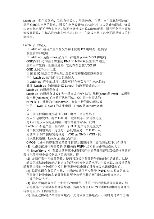
Latch up 的定义Latch up 最易产生在易受外部干扰的I/O电路处, 也偶尔发生在内部电路Latch up 是指cmos晶片中, 在电源power VDD和地线GND(VSS)之间由于寄生的PNP和NPN双极性BJT相互影响而产生的一低阻抗通路, 它的存在会使VDD和GND之间产生大电流随着IC制造工艺的发展, 封装密度和集成度越来越高,产生Latch up的可能性会越来越大Latch up 产生的过度电流量可能会使芯片产生永久性的破坏, Latch up 的防范是IC Layout 的最重要措施之一Latch up 的原理图分析Latch up 的原理分析Q1为一垂直式PNP BJT, 基极(base)是nwell, 基极到集电极(collector)的增益可达数百倍;Q2是一侧面式的NPN BJT,基极为P substrate,到集电极的增益可达数十倍;Rwell是nwell的寄生电阻;Rsub是substrate电阻。
以上四元件构成可控硅(SCR)电路,当无外界干扰未引起触发时,两个BJT处于截止状态,集电极电流是C-B的反向漏电流构成,电流增益非常小,此时Latch up不会产生。
当其中一个BJT的集电极电流受外部干扰突然增加到一定值时,会反馈至另一个BJT,从而使两个BJT因触发而导通,VDD至GND(VSS)间形成低抗通路,Latch up由此而产生。
CMOS电路中的寄生双极型晶体管部分出现闩锁,必须满足以下几个条件:(1) 电路要能进行开关转换,其相关的PNPN结构的回路增益必须大于1即βnpn*βpnp >1,在最近的研究中,把闩锁产生的条件用寄生双极晶体管的有效注入效率和小信号电流增益来表达。
EIAJESD78A-2006闩锁测试方法-20090513
冷却时间 Cool-down time
连续施加的触发脉冲之间的间歇时间或撤出 Vsupply 电压和下一个触发脉冲之间的时间。 (见图 2、3 和 4,及表 2)
待测器件 DUT
待测试器件。
地 GND(Ground)
DUT 的公共端或零电势端。 注 1 接地端不进行闩锁测试。 注 2 接地端有时称为 VSS 端。
给器件施加最小额定时钟频率,在已知稳定状态下对器件进行闩锁触发测试。
测试条件 Test condition
在闩锁测试时施加于 DUT 的测试温度、电源电压、电流限值、电压限值、时钟频率、 输入偏置电压和预置向量等。
EIA/JEDEC 78A 第4页
时间相关的输入引脚 Timing-related input pin
2 定义.............................................................................................................................................2 (二级目录删除)
将 DUT 置于正常工作模式而需要的诸如时钟晶振、电荷甭电路等相关引脚。 注 -适用时,要求的时间信号可以由闩锁测试设备、外部仪器,和/或外部元件提供。
触发脉冲 Trigger pulse
为触发闩锁而施加于器件引脚上的正向或负向电流脉冲(I-Test)或电压脉冲(Vsupply 过压测试)。(见图 2、3 和 4)
触发持续时间 Trigger duration
触发源提供的脉冲施加的持续时间。(见图 2、3 和 4,表 2)
电源引脚(或引脚组) Vsupply pin(or pin group)
hbm latchup mm cdm指标

HBM (Human Body Model)、Latchup、MM (Machine Model)和CDM (Charged Device Model)是集成电路领域中常见的指标,它们分别代表着集成电路在不同环境下对静电放电和瞬态电压的抗干扰能力。
本文将从这四个指标的定义、测试方法和应用领域等方面进行详细介绍。
一、HBM指标的定义和测试方法HBM是指人体模型,是用来模拟人体接触集成电路时产生的静电放电现象。
HBM测试是集成电路静电放电抗干扰能力的一项重要测试指标,它通过对集成电路引脚施加不同的静电电压脉冲,来测试集成电路对静电放电的承受能力。
HBM指标是以电压等级和脉冲波形来定义的,常见的HBM等级包括:1.5kV、2kV、4kV等,而脉冲波形包括:100ns、200ns等。
二、Latchup指标的定义和测试方法Latchup是指集成电路在工作过程中由于外部干扰或内部原因产生的永久性失控,导致集成电路无法正常工作的现象。
Latchup测试是用来评估集成电路在不同工作条件下对于外部干扰的抗干扰能力。
Latchup测试主要通过施加不同的电压或电流脉冲来模拟集成电路在工作过程中的外部干扰,从而评估其对Latchup现象的抵抗能力。
三、MM指标的定义和测试方法MM是指机器模型,是用来模拟集成电路在工作环境中对于瞬态电压的抗干扰能力的一项重要指标。
MM测试主要是通过对集成电路引脚施加不同的瞬态电压脉冲,来评估集成电路对瞬态电压的抵抗能力。
MM指标通常包括了电压等级和脉冲波形,如:100V、200V等电压等级,10ns、100ns等脉冲波形。
四、CDM指标的定义和测试方法CDM是指带电器件模型,是用来模拟集成电路在处理、运输、安装等过程中对于静电放电的抵抗能力的指标。
CDM测试是通过对集成电路设备进行特定的静电放电测试,来评估其对静电放电的抵抗能力。
CDM测试通常包括了不同的放电等级和测试条件,如:100V、200V 等放电等级,不同的测试方法和测试设备。
JESD78B_200812_LATCHUP标准

The information included in JEDEC standards and publications represents a sound approach to product specification and application, principally from the solid state device manufacturer
No claims to be in conformance with this standard may be made unless all requirements stated in the standard are met.
Inquiries, comments, and suggestions relative to the content of this JEDEC standard or publication should be addressed to JEDEC at the address below, or call (703) 907-7559 or
viewpoint. Within the JEDEC organization there are procedures whereby a JEDEC standard or publication may be further processed and ultimately become an ANSI standard.
by the JEDEC legal counsel.
JEDEC standards and publications are designed to serve the public interest through eliminating misunderstandings between manufacturers and purchasers, facilitating interchangeability and improvement of products, and assisting the purchaser in selecting and obtaining with minimum delay the proper product for use by those other than JEDEC members, whether the standard is to be
latchup的CMOS电路中闩锁,必须满足以下几个条件
latchup的CMOS电路中闩锁,必须满足以下几个条件(1) 电路要能进行开关转换,其相关的PNPN结构的回路增益必须大于1即βnpn*βpnp >1,在最近的研究中,把闩锁产生的条件用寄生双极晶体管的有效注入效率和小信号电流增益来表达。
即(2) 必须存在一种偏置条件,使两只双极型晶体管导通的时间足够长,以使通过阻塞结的电流能达到定义的开关转换电流的水平。
一般来说,双极管的导通都是由流过一个或两个发射极/基极旁路电阻的外部激发电流所引起的。
(3) 偏置电源和有关的电路,必须能够提供至少等于PNPN结构脱离阻塞态所需开关转换电流和必须能提供至少等于使其达到闩锁态的保持电流。
闩锁的触发方式(1) 输入或输出节点的上冲或下冲的触发,使第一个双极型晶体管导通,然后再使第二个双极型晶体管导通。
当流入寄生PNPN结构的总电流达到开关转换电流时,闩锁就发生。
(2) 当流过阱-衬底结的雪崩电流,光电流及位移电流,,同时通过两个旁路电阻RW,RS时,旁路电阻较大的晶体管先导通。
然而要使闩锁发生,第二个双极型晶体管必须导通。
同时通过PNPN结构的总电流必须达到开关转换电流。
(3) 当出现穿通,场穿通时,低阻通路一般发生在电源和地线之间,或者发生在电源和衬底发生器之间。
在源-漏发生雪崩击穿的情况下,低阻通路发生在电源和信号线之间,或者发生在信号线和衬底发生器之间。
这些来源于穿通,场穿通或漏结雪崩的电流,一旦PNPN结构的电流达到用取消被激发晶体管旁路电阻形成的三极管结构计算的开关转换电流时,至少会发生瞬时闩锁,若总电流也能达到四极管结构开关转换电流,即闩锁将维持下去。
闩锁的防止技术体硅CMOS中的闩锁效应起因于寄生NPN和PNP双极晶体管形成的PNPN结构,若能使两只晶体管的小信号电流增益之和小于1,闩锁就可防止。
一是将双极型晶体管的特性破坏掉,即通过改进CMOS制造工艺,用减少载流子运输或注入的方法来达到破坏双极型晶体管作用的目的,例如,掺金,中子辐射形成基区阻碍电场以及形成肖特基源/漏势垒等。
ESD与latchup测试介绍
6、拴锁测试
8、ESD测试标准和分类
根据ESD模式分类 HBM测试标准 MM测试标准 CDM测试标准 根据提出标准的组织分类 JESD22系列,JEDEC Solid State Technology Association (Joint Electron Device Engineering Council)提出 ANSI-ESDSTM5.X系列,ESDA协会提出 AEC-Q100系列,汽车电子委员会Automotive Electronics Council提出 MIL-STD-883E系列,美国军方国防部提出HBM 测试特点 HBM测试标准基本上是依据美国军方测试标准MIL-STD-883E改进而成 HBM和MM测试方法差不多������ ������ ������ ������ ������ ������ ������ ������ CDM测试方法和测试仪器与前两者差别大
我公司ESD与Latch up的测试规范
15-1002 集成电路ESD评估规范 15-1003 CMOS集成电路Latch-Up的评估 规范
IC制程特性有时会有小 幅的(10%) 漂移,所以 在相同批次IC中随机取 样至少大于5颗。
HMB ESD failure photo
3、CDM模型和测试方法标准
3、CDM模型和测试方法标准
6、拴锁测试
6、拴锁测试
6、拴锁测试
6、拴锁测试
使用curve tracter测试拴锁
人体放电模式 (Human-Body Model, HBM)
人体放电模式(HBM)的ESD是指因人体在地上走动磨擦或其它因素在人体上 已累积了静电,当此人去碰触到IC时,人体上的静电便会经由IC的脚(pin)而 进入IC内,再经由IC放电到地去,如图2.1-1(a)所示。此放电的过程会在短 到几百毫微秒(ns)的时 间内产生数安培的瞬间放电电流,此电流会把IC内的 组件 给烧毁。 不同HBM静电电压相对产生的瞬间放电电流与时间的关系 显 示于图2.1-1(b)。对一般商用IC的2-KV ESD放电电压而言,其瞬间放电电流 的尖峰值大约是1.33 安培。
latch up测试标准

latch up测试标准Latchup测试是电路设计中非常重要的一部分,用于确保电路在各种情况下都能正常工作。
本测试标准旨在为电路设计人员提供一套清晰、准确、可操作的测试方法,以确保Latchup现象不会对电路性能产生不良影响。
一、测试目的1.确保Latchup不会在电路中发生;2.验证Latchup防护措施的有效性;3.确保电路在不同工作条件下都能正常工作。
二、测试范围1.电源电路;2.信号传输线路;3.数字和模拟电路;4.芯片接口电路;5.其他可能发生Latchup的区域。
三、测试方法1.静态测试:a.使用示波器、电压表和电流表测量电路各部分的工作电压、电流及信号波形;b.检查电路中的电感和电容元件,确保其性能正常;c.对比设计图纸和实际电路,确保元件布局、布线符合设计要求。
2.动态测试:a.模拟不同的工作环境,如电压波动、温度变化等;b.引入干扰信号,模拟Latchup条件;c.使用测试仪器观察电路各部分的工作状态,如电压、电流、信号质量等;d.观察Latchup发生时的现象,如电压下降、电流增大、信号畸变等。
3.防护措施测试:a.对电路中的Latchup防护措施(如箝位二极管、磁珠等)进行测试;b.验证这些防护措施在Latchup发生时的反应时间、抑制效果等性能指标;c.检查防护措施对电路其他部分的影响。
四、测试标准tchup现象未在电路中发生;2.电路在各种工作条件下都能正常工作,无异常现象;3.保护措施在Latchup发生时能迅速起作用,抑制效果良好;4.干扰信号对其他电路部分的影响在可接受范围内。
五、测试周期与记录1.每次设计变更后都应进行Latchup测试;2.测试结果应记录在案,便于日后查阅;3.对于多次出现问题的区域,应进行深入分析,找出根本原因。
通过遵循本测试标准,电路设计人员可以更准确地评估电路的安全性和可靠性,为产品的质量和性能提供有力保障。
拉头测试标准

拉头测试标准
拉头测试标准通常涉及多个方面,包括拉头的材料、结构、性能等。
以下是一些常见的拉头测试标准:
拉头强度测试:测试拉头在受到拉伸力时的强度,以确保其能够承受一定的拉力而不损坏。
这通常涉及使用专业的测试设备对拉头进行拉伸测试,并记录其承受的最大拉力。
拉头耐磨性测试:测试拉头在受到摩擦时的耐磨性能,以确保其能够长时间使用而不磨损。
这通常涉及使用摩擦试验机对拉头进行摩擦测试,并记录其磨损程度。
拉头耐腐蚀性测试:测试拉头在受到腐蚀环境时的耐腐蚀性能,以确保其能够在恶劣环境下长时间使用而不受损。
这通常涉及将拉头暴露在腐蚀环境中,观察其是否出现腐蚀现象。
需要注意的是,具体的拉头测试标准可能因不同的行业、产品和应用场景而有所不同。
因此,在实际应用中,需要根据具体情况选择适当的测试标准,并遵循相应的测试方法和要求进行测试。
- 1、下载文档前请自行甄别文档内容的完整性,平台不提供额外的编辑、内容补充、找答案等附加服务。
- 2、"仅部分预览"的文档,不可在线预览部分如存在完整性等问题,可反馈申请退款(可完整预览的文档不适用该条件!)。
- 3、如文档侵犯您的权益,请联系客服反馈,我们会尽快为您处理(人工客服工作时间:9:00-18:30)。
latch up测试标准
Latch up是指集成电路中的一种失效现象,当一个晶体管或器件被误用时,或由于外界干扰等原因导致,会出现电流过大的现象,从
而导致电路失效或损坏。
Latch up测试是为了验证电路的稳定性和可靠性,以确保电路能够正常工作并长期稳定运行。
Latch up是一种瞬态故障,通常发生在集成电路中存在PNPN结构的电路,例如CMOS电路或双极性晶体管。
这种结构使得电路在特定条件下会形成一个自反馈回路,导致电流大幅度增加,进而导致电路失效。
Latch up测试通常包括以下步骤:
1.设计电路:首先,在设计电路时需要充分考虑到避免触发Latch up现象的条件。
例如,采用合适的工艺参数和结构设计,选择适当的尺寸和电流容限,并避免形成PNPN结构的电路。
2.模拟仿真:使用电路仿真软件进行模拟分析,验证设计电路的
稳定性和可靠性。
通过模拟仿真,可以观察电路在边界条件下是否可
能出现Latch up现象。
3.制造过程控制:在芯片制造过程中,需要严格控制工艺参数和
制造流程,以确保电路的稳定性。
例如,控制晶体管制造的掺杂浓度、尺寸和位置,避免PNPN结构的形成。
4.电流注入测试:进行电流注入测试是验证电路是否存在Latch
up现象的重要步骤。
通常,将高电压施加到电路的输入、输出端口,
然后测量电路中的电流变化。
如果电流显著增加,就说明电路存在
Latch up现象。
5.温度测试:温度是影响电路稳定性的重要因素,因此进行温度
测试可以验证电路在不同温度条件下的工作情况。
在温度测试中,可
以观察电路在不同温度下的电流变化和稳定性。
6.电压应力测试:电压应力测试是在电路上施加不同的电压,并
监测电流的变化。
通过电压应力测试,可以验证电路在不同电压条件
下的稳定性和可靠性。
7.压耐测试:压耐测试是对电路进行高电压的耐受能力测试。
在
压耐测试中,会施加高于设计电压的电压,并观察电路的稳定性和可
靠性。
如果电路能够正常工作且没有失效,说明电路具有良好的压耐
性能。
通过以上的测试步骤,可以有效地评估电路的稳定性和可靠性,
并检测和解决可能存在的Latch up问题。
同时,也可以通过测试结果
来指导电路设计和制造流程的改进,以进一步优化电路的稳定性和可
靠性。
总结起来,Latch up测试是为了保证集成电路的稳定性和可靠性,通过模拟仿真、制造过程控制以及电流注入、温度、电压应力和压耐
等测试手段,确保电路能够正常工作并长期稳定运行。
这些测试步骤
可以帮助发现问题,并指导电路设计和制造流程的改进,以提高电路
的性能和可靠性。
