LATCH UP 测试分析
ESD与latchup测试介绍
1、ESD模型分类 2、HBM和MM测试方法标准 3、 CDM模型和测试方法标准 4、拴锁测试 5、 I-V测试 6、标准介绍
1、ESD模型分类
因ESD产生的原因及其对集成电路放电的方式不同, 经过统计,ESD放电模型分下列四类:
(1) 人体放电模式 (Human-Body Model, HBM) (2) 机器放电模式 (Machine Model, MM) (3) 组件充电模式 (Charged-Device Model, CDM) (4) 电场感应模式 (Field-Induced Model, FIM) 另外还有两个测试模型: (5)对于系统级产品测试的IEC电子枪空气放电模式 (6)对于研究设计用的TLP模型
人体放电模式 (Human-Body Model, HBM)
人体放电模式(HBM)的ESD是指因人体在地上走动磨擦或其它因素在人体上 已累积了静电,当此人去碰触到IC时,人体上的静电便会经由IC的脚(pin)而 进入IC内,再经由IC放电到地去,如图2.1-1(a)所示。此放电的过程会在短 到几百毫微秒(ns)的时 间内产生数安培的瞬间放电电流,此电流会把IC内的 组件 给烧毁。 不同HBM静电电压相对产生的瞬间放电电流与时间的关系 显 示于图2.1-1(b)。对一般商用IC的2-KV ESD放电电压而言,其瞬间放电电流 的尖峰值大约是1.33 安培。
有关FIM的放电模式早在双载子(bipolar)晶体管时代 就已被发现,现今已有工业测试标准。
国际电子工业标准(EIA/JEDEC STANDARD) 中亦 有此电场感应模式订定测试规范 (JESD22-C101) 。
HBM, MM与CDM模型参数比较
2KV HBM, 200V MM, 与1KV CDM的放电电流比较,其中1KV CDM的放电电流 在不到1ns的时间内,便已冲到约15安培的尖峰值,但其放电的总时段约在10ns的 时间内便结束。此种放电现象更易造成集成电路的损伤。
闩锁效应latch up

闩锁效应(latch up)闩锁效应(latch up)是CMOS必须注意的现象,latch我认为解释为回路更合适,大家以后看到latch up就联想到在NMOS与PMOS里面的回路,其实你就懂了一半了.为什么它这么重要?因为它会导致整个芯片的失效,所以latch up是QUAL测试的一种,并且与ESD(静电防护)紧密相关。
第一部分 latch up的原理我用一句最简单的话来概括,大家只要记住这句话就行了:latch-up是PNPN的连接,本质是两个寄生双载子transisitor的连接,每一个transistor的基极(base)与集极(collector)相连,也可以反过来说,每一个transistor的集极(collector)与另一个transistor的基极(base)相连,形成positive feedback loop(正回馈回路),下面我分别解释。
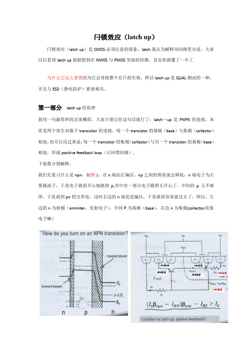
我们先复习什么是npn,如图1,在n端加正偏压,np之间的势垒就会降低,n端电子为主要载流子,于是电子就很开心地跑到p,其中有一部分电子跑得太开心了,中间的p又不够厚,于是就到pn的交界处,这时右边的n端是逆偏压,于是就很容易就过去了。
所以,左边的n为射极(emmiter,发射电子),中间P为基极(base),右边n为集极(collector,收集电子嘛)理解了npn,那么pnp就好办,如图2。
图2清楚的表示了latch up的回路。
左边是npn,右边是pnp,图3是电路示意图。
大家可以看出,P-sub既是npn的基极,又是pnp的集极;n-well既是既是pnp的基极,又是npn的集极,所以说,每一个transistor的集极(collector)与另一个transistor的基极(base)相连。
那么电流怎么走呢?比如在P+加5V-->电洞被从P+推到N well-->越过n well再到p sub-->这个时候,大家注意,电洞有两条路可走,一是跑到NMOS的N+,二是跑到旁边的Nwell,nwell比n+深,当然更好去,所以电洞又回去了。
latch up测试标准

latch up测试标准Latch up是指集成电路中的一种失效现象,当一个晶体管或器件被误用时,或由于外界干扰等原因导致,会出现电流过大的现象,从而导致电路失效或损坏。
Latch up测试是为了验证电路的稳定性和可靠性,以确保电路能够正常工作并长期稳定运行。
Latch up是一种瞬态故障,通常发生在集成电路中存在PNPN结构的电路,例如CMOS电路或双极性晶体管。
这种结构使得电路在特定条件下会形成一个自反馈回路,导致电流大幅度增加,进而导致电路失效。
Latch up测试通常包括以下步骤:1.设计电路:首先,在设计电路时需要充分考虑到避免触发Latch up现象的条件。
例如,采用合适的工艺参数和结构设计,选择适当的尺寸和电流容限,并避免形成PNPN结构的电路。
2.模拟仿真:使用电路仿真软件进行模拟分析,验证设计电路的稳定性和可靠性。
通过模拟仿真,可以观察电路在边界条件下是否可能出现Latch up现象。
3.制造过程控制:在芯片制造过程中,需要严格控制工艺参数和制造流程,以确保电路的稳定性。
例如,控制晶体管制造的掺杂浓度、尺寸和位置,避免PNPN结构的形成。
4.电流注入测试:进行电流注入测试是验证电路是否存在Latchup现象的重要步骤。
通常,将高电压施加到电路的输入、输出端口,然后测量电路中的电流变化。
如果电流显著增加,就说明电路存在Latch up现象。
5.温度测试:温度是影响电路稳定性的重要因素,因此进行温度测试可以验证电路在不同温度条件下的工作情况。
在温度测试中,可以观察电路在不同温度下的电流变化和稳定性。
6.电压应力测试:电压应力测试是在电路上施加不同的电压,并监测电流的变化。
通过电压应力测试,可以验证电路在不同电压条件下的稳定性和可靠性。
7.压耐测试:压耐测试是对电路进行高电压的耐受能力测试。
在压耐测试中,会施加高于设计电压的电压,并观察电路的稳定性和可靠性。
如果电路能够正常工作且没有失效,说明电路具有良好的压耐性能。
ESD与latchup测试介绍解读

HBM测试方法及标准 1.ANSI-STM5.1-2001 JESD22-A114D -2005 AEC-Q100-002D -2003 2.该标准用于明确HBM模式下的ESD电压敏感度的 测试、评价以及分级过程 3.整个测试过程繁琐,尤其对仪器及脉冲波形的校 验工作,但非常必要 4. ESD测试中,器件不在工作状态
FIM模式的静电放电发生是因电场感应而起的。当 IC因输送带或其它因素而经过一电场时,其相对 极性的电荷可能会自一些IC脚而排放掉,等IC通 过电场之后,IC本身便累积了静电荷,此静电荷 会以类似CDM的模式放电出来。
有关FIM的放电模式早在双载子(bipolar)晶体管时代 就已被发现,现今已有工业测试标准。 国际电子工业标准(EIA/JEDEC STANDARD) 中亦 有此电场感应模式订定测试规范 (JESD22-C101) 。
ESD模型及有关测试
1、ESD模型分类 2、HBM和MM测试方法标准 3、 CDM模型和测试方法标准 4、拴锁测试 5、 I-V测试 6、标准介绍
1、ESD模型分类
因ESD产生的原因及其对集成电路放电的方式不同, 经过统计,ESD放电模型分下列四类: (1) 人体放电模式 (Human-Body Model, HBM) (2) 机器放电模式 (Machine Model, MM) (3) 组件充电模式 (Charged-Device Model, CDM) (4) 电场感应模式 (Field-Induced Model, FIM) 另外还有两个测试模型: (5)对于系统级产品测试的IEC电子枪空气放电模式 (6)对于研究设计用的TLP模型
HBM/MM测量方法
如果每次调升的ESD测试电压调幅太小,则测试到IC脚损坏要 经过多次的ESD放电,增长测试时间; 若每次调升的ESD测试电 压太大,则难以较精确测出该IC脚的ESD耐压能力。 规定: 正负极性均要测试 从低压测到高压,起始电压为70%的平均ESD failure threshold (VESD) 步进当小于1000V时步进50V(100V),大于1000V时步进 100V(250V, 500V) 可以是一个管脚步进测量或者所有管脚扫描测量
ESD,Latch-up测试 介绍
*ESDA DS5.3.2 (草案) 美國靜電協會
2. 非插座式器件充電模型 CDM (Non-Socketed CDM)
*ESDA STM5.3.1美國靜電協會 *JEDEC EIA/JESD22-C101-B
電子工業協會
*AEC-Q100-011-REV-A 汽車電子協會
ESD的一般要求 *HBM: >=2kV (軍標亦要求>2kV) *MM: >=200V *CDM: >=700V~1000V
ESD Design Window
Pin Combination in HBM/MM ESD Testing
判定等级
受ESD影响现像
A
测试过程功能完全正常,不受影响
B
功能暂时性受影响,但可自动回复
C
功能受ESD影响出现异常, 须人为重置或重开机排除.
D
重开机功能也不能回复, 已损坏.
IEC 61000-4-2 ESD测试判定等级
结果 合格 合格 不合格 不合格
ESD/Latch-Up 2. IC ESD Test
ESD/Latch-Up
1. 电子产品ESD测试介绍
* 整机产品ESD Test (System ESD Test)
a). Contact Discharge b). Air Discharge
* IC ESD Test
a). HBM-Human Body Model b). MM-Machine Model c). CDM-Charged Device Model
電子工業協會
*AEC-Q100-002-REV-C 汽車電子協會
latch up原理

latch up原理
Latch up原理也被称为“瞬间自锁”,是电路设计和测试中需要特别
注意的一种现象。
简单地说,Latch up是指由于某些原因,一个双极
晶体管(BJT)或MOSFET绝缘体(MOSFET),在其电路中形成一
个临时短路,从而导致器件失效或被损坏。
Latch up现象通常在集成电路中出现,尤其在高密度集成电路中更为
常见。
在模拟电路中,Latch up现象可能会导致噪音增加,失真增加,甚至一些器件被完全烧毁。
因此,Latch up问题对于电路设计师和测
试人员来说是一种常见的故障。
Latch up的原因是多方面的。
通常情况下,它是由于IC中存在两个或多个PN结,以及多种原因所引起的。
例如,设备的工作情况和晶体
管中的电源电压和电流都会影响此现象的出现概率。
超过器件设计的
最大电流和电压也会导致Latch up,此时晶体管就会像一个快速的电
子开关而不是一个灵敏的控制器。
为了避免Latch up的问题发生,电路设计师需要在设计中考虑PN结的位置和数量,并使用合适的工艺方法来降低PN结的电压容限。
此外,还建议通过在PCB上放置解决这一问题的集成电路,使用具有专业化的工具来测试电路,并遵循厂商发布的规定修订。
</p
总之,Latch up是电路设计中需要特别注意和避免的问题。
在设计和测试过程中,通过精确计算和适当的方法来避免Latch up可能发生的影响,可以降低电路故障和失效的概率,从而提高设备的稳定性和可靠性。
latch-up版图
latch-up原理分析
I n Out N+ P+ P+ Q1 Q2 N+ N+ P+
R w ell N w ell P- e p i
R su b P+s u b
华侨大学厦门专用集成电路系统重点实验室
Copyright by Huang Weiwei
latch-up原理分析
I n Out N+ P+ P+ Q1 Q1 Q2 OUT R su b P+s u b R su b Q2 OUT N+ N+ P+ R w ell
R su b
Q2
华侨大学厦门专用集成电路系统重点实验室
Copyright by Huang Weiwei
latch-up原理分析
I n Out N+ P+ P+ Q1 Q2 N+ N+ P+ R w ell N w ell P- e p i R su b P+s u b
Latch up的具体原因5 5 产生Latch up
OUT Q1
R w ell
R su b
Q2
华侨大学厦门专用集成电路系统重点实验室
Copyright by Huang Weiwei
latch-up原理分析
I n Out N+ P+ P+ Q1 Q2 N+ N+ P+ R w ell N w ell P- e p i R su b P+ s u b
华侨大学厦门专用集成电路系统重点实验室
Copyright by Huang Weiwei
latch-up保护方法
latch_up分析
闩锁效应(latch up)闩锁效应(latch up)是CMOS必须注意的现象,latch我认为解释为回路更合适,大家以后看到latch up就联想到在NMOS与PMOS里面的回路,其实你就懂了一半了.为什么它这么重要因为它会导致整个芯片的失效,所以latch up是QUAL测试的一种,并且与ESD(静电防护)紧密相关。
第一部分latch up的原理我用一句最简单的话来概括,大家只要记住这句话就行了:latch-up是PNPN的连接,本质是两个寄生双载子transisitor的连接,每一个transistor的基极(base)与集极(collector)相连,也可以反过来说,每一个transistor的集极(collector)与另一个transistor的基极(base)相连,形成positive feedback loop(正回馈回路),下面我分别解释。
我们先复习什么是npn,如图1,在n端加正偏压,np之间的势垒就会降低,n端电子为主要载流子,于是电子就很开心地跑到p,其中有一部分电子跑得太开心了,中间的p又不够厚,于是就到pn的交界处,这时右边的n端是逆偏压,于是就很容易就过去了。
所以,左边的n为射极(emmiter,发射电子),中间P为基极(base),右边n为集极(collector,收集电子嘛)理解了npn,那么pnp就好办,如图2。
图2清楚的表示了latch up的回路。
左边是npn,右边是pnp图3是电路示意图。
大家可以看出,P-sub既是npn的基极,又是pnp的集极;n-well既是既是pnp的基极,又是npn的集极,所以说,每一个transistor的集极(collector)与另一个transistor的基极(base)相连。
那么电流怎么走呢比如在P+加5V-->电洞被从P+推到N well-->越过n well再到p sub-->这个时候,大家注意,电洞有两条路可走,一是跑到NMOS的N+,二是跑到旁边的Nwell,nwell比n+深,当然更好去,所以电洞又回去了。
ESD,Latch-up测试 介绍

ESD 测试设备
ESD
HBM / MM/ CDM
Latch-up
There are three models in IST used to perform the ESD testing, ESD(HBM/MM/CDM)
ESD / Latch-up capability :
Model-1(256 pin): Zap Master 7/4, 256 pins
*Trigger Current/Voltage(激發電流/電壓)
1. I/O: (一般管腳) 正電流: +100mA 負電流: -100mA 2. Power Pin (電源管腳): 1.5xVmax.
以上為JEDEC 78A之規定 AEC對於I/O管腳需加測電壓激發至1.5xVmax
ESD/Latch-Up
2.1人體模型(HBM-Human Body ) Model
*MIL-STD-883G Method 3015.7 notice 8
美國軍標883
*ESDA STM5.1-1998 美國靜電協會 *JEDEC EIA/JESD22-A114-E
Special
IEC 61000-4-2 放 电 示 意 图
IEC 61000-4-2 放 电 Waveform
IEC 61000-4-2 测试结果评估判定
ESD测试结果评估须按被测试产品功能受影响的程度做判定, 依法规系将受影响的程度分为四级,说明如下:
+ +
+
Zapmaster 選項可以執行SCDM 測試
ESD/Latch-Up 器件充電模型波形
高電流 8.0
芯片IC测试专栏—LatchUp测试

芯片IC测试专栏—LatchUp测试大家都知道IC芯片的可靠性是芯片能不能正常量产的重要指标,那么IC的可靠性都包括哪些呢?ESD(HBM,CDM),HTOL(老化测试),HAST(封装可靠性测试),BHAST(偏压可靠性测试),当然还有芯片的LatchUp测试,本文中,我不会介绍为什么要进行LatchUp 测试,只是要介绍一下LatchUp到底要测什么,测试条件是怎么样的?首先,消费级IC芯片的LatchUp测试主要依据标准JESD78进行测试,当然,会有专门的仪器设备进行测试,通常IC芯片出来之后,会委托第三方实验室进行LatchUp测试,(第三方实验室可以出一个测试报告,这样客户的认可度会比较高,而且设备仪器不用购买以及维护)。
那么详细的测试条件和测试步骤分别是什么呢?首先,是环境温度,有两种,第一种就是在常温进行测试;另外一种就是规定温度下的测试,如最大运行温度,最大运行结温,或者是客户指明的温度等等。
这一条件,只需要告诉第三方实验室即可设置。
然后呢就要进行Latchup的测试,主要分为3个部分,其实可以总结为两部分,一是电流测试,另一个是电压测试:1.电流测试电流测试分为两部分,正电流测试(灌入电流)和负电流测试(拉电流),主要是对普通IO进行电流测试。
正电流测试负电流测试上面两张图描述了正负电流测试过程中芯片电源和测试IO的电压波形。
大概如下:测试开始时,给芯片VDD上电,然后测量一个正常情况下的VDD的耗电值,Inormal,之后,给IO加电压(正电流测试时,加最大电压,负电流测试时,加最小电压),然后,对IO进行正负电流的测试,那么IO上的电压会升高或者降低(注意:IO引脚上的电压会限压,防止芯片是因为过压而损坏,具体计算公式在测试标准有),过一段时间之后(至少10us,最大1s), IO 上的正负电流去掉,稳定一段时间之后,再次测量VDD的耗电,Inormal2,比较前后两个电流值,进行判断,如果Inormal <=25mA,那么Inormal2必须小于Inormal+10mA,如果Inormal >25mA,那么Inormal2必须小于1.4*Inormal。
LATCH UP 测试分析

LATCH UP 测试LATCH UP 测试。
但是,以前我没做过类似的工作,因为以前的公司的芯片LATCH UP测试都是找宜硕这样的公司进行测试。
LATCH UP测试主要分为VSUPPLY OVER VOLTAGE TEST ,I TEST。
I test又分为PIT(POSITIVE I TEST)和NIT(NEGATIVE I TEST)。
不过我们公司还增加了PVT(positive voltage test)和NVT(negative voltage test)。
在JESD78D 规范(这个可以从JEDEC 网站上下到)上提到latch up 的测试流程。
首先待测试的IC 需要经过ATE测试,保证功能是正常的。
然后首先进行I-TEST,如果I-TEST FAIL,那这颗芯片就没PASS,如果通过了I-TEST,然后再进行OVER VOLTAGE TEST; 如果此时IC FAIL,那么这颗芯片就没有通过LATCH UP TEST, 这些通过I-TEST 和OVER VOLTAGE TEST的芯片还要再进行ATE测试来确认芯片的功能是否正常。
但是好多公司最后的ATE测试都省了。
VSUPPLY OVER VOLTAGE TEST,主要是对芯片的电源引脚进行过压测试,如果芯片有多个电源引脚,每个电源引脚都要进行测试。
测试条件:一般是对电压引脚进行一个 1.5X MAX VSUPPLY的TRIGGER 测试,1)其他引脚接LOGIC HIGH, 2)其他引脚接LOGIC LOW。
这两种情况都要进行测试。
PIT 测试是对除电源和地外的其他I/O引脚进行测试。
电源接VCC,1)所有引脚接LOGIC HIGH, 然后给待测试引脚来一个POSITIVE TRIGGER CURRENT PULSE。
2)所有引脚接LOGIC LOW,然后给待测试引脚来一个POSITIVE TRIGGER CURRENT PULSE。
latch_up分析

闩锁效应(latch up)闩锁效应(latch up)是CMOS必须注意的现象,latch我认为解释为回路更合适,大家以后看到latch up就联想到在NMOS与PMOS里面的回路,其实你就懂了一半了.为什么它这么重要?因为它会导致整个芯片的失效,所以latch up是QUAL测试的一种,并且与ESD(静电防护)紧密相关。
第一部分latch up的原理我用一句最简单的话来概括,大家只要记住这句话就行了:latch-up是PNPN的连接,本质是两个寄生双载子transisitor的连接,每一个transistor的基极(base)与集极(collector)相连,也可以反过来说,每一个transistor的集极(collector)与另一个transistor的基极(base)相连,形成positive feedback loop(正回馈回路),下面我分别解释。
我们先复习什么是npn,如图1,在n端加正偏压,np之间的势垒就会降低,n端电子为主要载流子,于是电子就很开心地跑到p,其中有一部分电子跑得太开心了,中间的p又不够厚,于是就到pn的交界处,这时右边的n端是逆偏压,于是就很容易就过去了。
所以,左边的n为射极(emmiter,发射电子),中间P为基极(base),右边n为集极(collector,收集电子嘛)理解了npn,那么pnp就好办,如图2。
图2清楚的表示了latch up的回路。
左边是npn,右边是pnp图3是电路示意图。
大家可以看出,P-sub既是npn的基极,又是pnp的集极;n-well既是既是pnp的基极,又是npn的集极,所以说,每一个transistor的集极(collector)与另一个transistor的基极(base)相连。
那么电流怎么走呢?比如在P+加5V-->电洞被从P+推到N well-->越过n well再到p sub-->这个时候,大家注意,电洞有两条路可走,一是跑到NMOS的N+,二是跑到旁边的Nwell,nwell比n+深,当然更好去,所以电洞又回去了。
latch-up描述
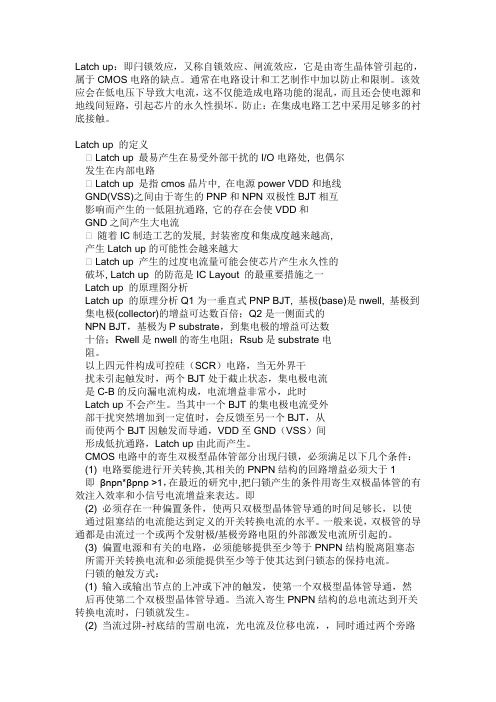
Latch up:即闩锁效应,又称自锁效应、闸流效应,它是由寄生晶体管引起的,属于CMOS电路的缺点。
通常在电路设计和工艺制作中加以防止和限制。
该效应会在低电压下导致大电流,这不仅能造成电路功能的混乱,而且还会使电源和地线间短路,引起芯片的永久性损坏。
防止:在集成电路工艺中采用足够多的衬底接触。
Latch up 的定义Latch up 最易产生在易受外部干扰的I/O电路处, 也偶尔发生在内部电路Latch up 是指cmos晶片中, 在电源power VDD和地线GND(VSS)之间由于寄生的PNP和NPN双极性BJT相互影响而产生的一低阻抗通路, 它的存在会使VDD和GND之间产生大电流随着IC制造工艺的发展, 封装密度和集成度越来越高,产生Latch up的可能性会越来越大Latch up 产生的过度电流量可能会使芯片产生永久性的破坏, Latch up 的防范是IC Layout 的最重要措施之一Latch up 的原理图分析Latch up 的原理分析Q1为一垂直式PNP BJT, 基极(base)是nwell, 基极到集电极(collector)的增益可达数百倍;Q2是一侧面式的NPN BJT,基极为P substrate,到集电极的增益可达数十倍;Rwell是nwell的寄生电阻;Rsub是substrate电阻。
以上四元件构成可控硅(SCR)电路,当无外界干扰未引起触发时,两个BJT处于截止状态,集电极电流是C-B的反向漏电流构成,电流增益非常小,此时Latch up不会产生。
当其中一个BJT的集电极电流受外部干扰突然增加到一定值时,会反馈至另一个BJT,从而使两个BJT因触发而导通,VDD至GND(VSS)间形成低抗通路,Latch up由此而产生。
CMOS电路中的寄生双极型晶体管部分出现闩锁,必须满足以下几个条件:(1) 电路要能进行开关转换,其相关的PNPN结构的回路增益必须大于1即βnpn*βpnp >1,在最近的研究中,把闩锁产生的条件用寄生双极晶体管的有效注入效率和小信号电流增益来表达。
EIAJESD78A-2006闩锁测试方法-20090513
冷却时间 Cool-down time
连续施加的触发脉冲之间的间歇时间或撤出 Vsupply 电压和下一个触发脉冲之间的时间。 (见图 2、3 和 4,及表 2)
待测器件 DUT
待测试器件。
地 GND(Ground)
DUT 的公共端或零电势端。 注 1 接地端不进行闩锁测试。 注 2 接地端有时称为 VSS 端。
给器件施加最小额定时钟频率,在已知稳定状态下对器件进行闩锁触发测试。
测试条件 Test condition
在闩锁测试时施加于 DUT 的测试温度、电源电压、电流限值、电压限值、时钟频率、 输入偏置电压和预置向量等。
EIA/JEDEC 78A 第4页
时间相关的输入引脚 Timing-related input pin
2 定义.............................................................................................................................................2 (二级目录删除)
将 DUT 置于正常工作模式而需要的诸如时钟晶振、电荷甭电路等相关引脚。 注 -适用时,要求的时间信号可以由闩锁测试设备、外部仪器,和/或外部元件提供。
触发脉冲 Trigger pulse
为触发闩锁而施加于器件引脚上的正向或负向电流脉冲(I-Test)或电压脉冲(Vsupply 过压测试)。(见图 2、3 和 4)
触发持续时间 Trigger duration
触发源提供的脉冲施加的持续时间。(见图 2、3 和 4,表 2)
电源引脚(或引脚组) Vsupply pin(or pin group)
latch up及天线效应
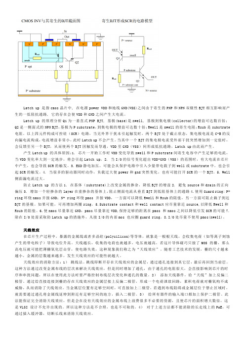
Latch up 是指cmos晶片中, 在电源power VDD和地线GND(VSS)之间由于寄生的PNP和NPN双极性BJT相互影响而产生的一低阻抗通路, 它的存在会使VDD和GND之间产生大电流。
Latch up 的原理分析Q1为一垂直式PNP BJT, 基极(base)是nwell, 基极到集电极(collector)的增益可达数百倍;Q2是一侧面式的NPN BJT,基极为P substrate,到集电极的增益可达数十倍;Rwell是nwell的寄生电阻;Rsub是substrate 电阻。
以上四元件构成可控硅(SCR)电路,当无外界干扰未引起触发时,两个BJT处于截止状态,集电极电流是C-B的反向漏电流构成,电流增益非常小,此时Latch up不会产生。
当其中一个BJT的集电极电流受外部干扰突然增加到一定值时,会反馈至另一个BJT,从而使两个BJT因触发而导通,VDD至GND(VSS)间形成低抗通路,Latch up由此而产生。
产生Latch up 的具体原因:1. 芯片一开始工作时VDD变化导致nwell和P substrate间寄生电容中产生足够的电流,当VDD变化率大到一定地步,将会引起Latch up。
2. 当I/O的信号变化超出VDD-GND(VSS)的范围时,有大电流在芯片中产生,也会导致SCR的触发。
3. ESD静电加压,可能会从保护电路中引入少量带电载子到well或substrate中,也会引起SCR的触发。
4. 当很多的驱动器同时动作,负载过大使power和gnd突然变化,也有可能打开SCR的一个BJT。
5. Well 侧面漏电流过大。
防止Latch up 的方法1. 在基体(substrate)上改变金属的掺杂,降低BJT的增益2. 避免source和drain的正向偏压3. 增加一个轻掺杂的layer在重掺杂的基体上,阻止侧面电流从垂直BJT到低阻基体上的通路4.使用Guard ring: P+ ring环绕nmos并接GND;N+ ring环绕pmos 并接VDD,一方面可以降低Rwell和Rsub的阻值,另一方面可阻止栽子到达BJT的基极。
hbm latchup mm cdm指标

HBM (Human Body Model)、Latchup、MM (Machine Model)和CDM (Charged Device Model)是集成电路领域中常见的指标,它们分别代表着集成电路在不同环境下对静电放电和瞬态电压的抗干扰能力。
本文将从这四个指标的定义、测试方法和应用领域等方面进行详细介绍。
一、HBM指标的定义和测试方法HBM是指人体模型,是用来模拟人体接触集成电路时产生的静电放电现象。
HBM测试是集成电路静电放电抗干扰能力的一项重要测试指标,它通过对集成电路引脚施加不同的静电电压脉冲,来测试集成电路对静电放电的承受能力。
HBM指标是以电压等级和脉冲波形来定义的,常见的HBM等级包括:1.5kV、2kV、4kV等,而脉冲波形包括:100ns、200ns等。
二、Latchup指标的定义和测试方法Latchup是指集成电路在工作过程中由于外部干扰或内部原因产生的永久性失控,导致集成电路无法正常工作的现象。
Latchup测试是用来评估集成电路在不同工作条件下对于外部干扰的抗干扰能力。
Latchup测试主要通过施加不同的电压或电流脉冲来模拟集成电路在工作过程中的外部干扰,从而评估其对Latchup现象的抵抗能力。
三、MM指标的定义和测试方法MM是指机器模型,是用来模拟集成电路在工作环境中对于瞬态电压的抗干扰能力的一项重要指标。
MM测试主要是通过对集成电路引脚施加不同的瞬态电压脉冲,来评估集成电路对瞬态电压的抵抗能力。
MM指标通常包括了电压等级和脉冲波形,如:100V、200V等电压等级,10ns、100ns等脉冲波形。
四、CDM指标的定义和测试方法CDM是指带电器件模型,是用来模拟集成电路在处理、运输、安装等过程中对于静电放电的抵抗能力的指标。
CDM测试是通过对集成电路设备进行特定的静电放电测试,来评估其对静电放电的抵抗能力。
CDM测试通常包括了不同的放电等级和测试条件,如:100V、200V 等放电等级,不同的测试方法和测试设备。
Latchup 失效分析(by Ming-Dou Ker 2006)
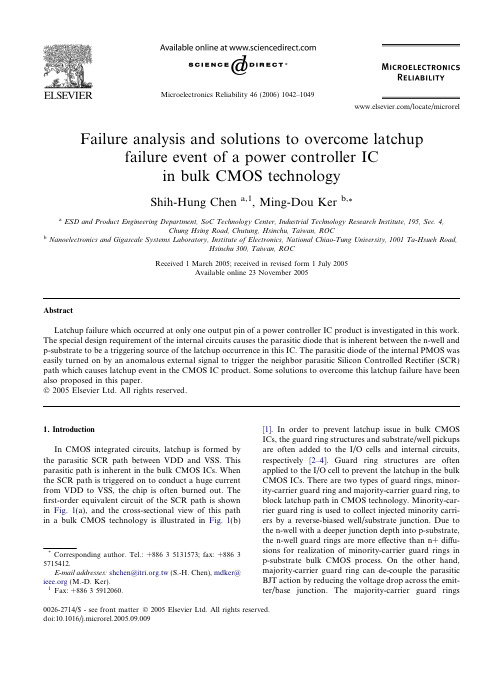
Failure analysis and solutions to overcome latchupfailure event of a power controller ICin bulk CMOS technologyShih-Hung Chena,1,Ming-Dou Kerb,*aESD and Product Engineering Department,SoC Technology Center,Industrial Technology Research Institute,195,Sec.4,Chung Hsing Road,Chutung,Hsinchu,Taiwan,ROCbNanoelectronics and Gigascale Systems Laboratory,Institute of Electronics,National Chiao-Tung University,1001Ta-Hsueh Road,Hsinchu 300,Taiwan,ROCReceived 1March 2005;received in revised form 1July 2005Available online 23November 2005AbstractLatchup failure which occurred at only one output pin of a power controller IC product is investigated in this work.The special design requirement of the internal circuits causes the parasitic diode that is inherent between the n-well and p-substrate to be a triggering source of the latchup occurrence in this IC.The parasitic diode of the internal PMOS was easily turned on by an anomalous external signal to trigger the neighbor parasitic Silicon Controlled Rectifier (SCR)path which causes latchup event in the CMOS IC product.Some solutions to overcome this latchup failure have been also proposed in this paper.Ó2005Elsevier Ltd.All rights reserved.1.IntroductionIn CMOS integrated circuits,latchup is formed by the parasitic SCR path between VDD and VSS.This parasitic path is inherent in the bulk CMOS ICs.When the SCR path is triggered on to conduct a huge current from VDD to VSS,the chip is often burned out.The first-order equivalent circuit of the SCR path is shown in Fig.1(a),and the cross-sectional view of this path in a bulk CMOS technology is illustrated in Fig.1(b)[1].In order to prevent latchup issue in bulk CMOS ICs,the guard ring structures and substrate/well pickups are often added to the I/O cells and internal circuits,respectively [2–4].Guard ring structures are often applied to the I/O cell to prevent the latchup in the bulk CMOS ICs.There are two types of guard rings,minor-ity-carrier guard ring and majority-carrier guard ring,to block latchup path in CMOS technology.Minority-car-rier guard ring is used to collect injected minority carri-ers by a reverse-biased well/substrate junction.Due to the n-well with a deeper junction depth into p-substrate,the n-well guard rings are more effective than n+diffu-sions for realization of minority-carrier guard rings in p-substrate bulk CMOS process.On the other hand,majority-carrier guard ring can de-couple the parasitic BJT action by reducing the voltage drop across the emit-ter/base junction.The majority-carrier guard rings0026-2714/$-see front matter Ó2005Elsevier Ltd.All rights reserved.doi:10.1016/j.microrel.2005.09.009*Corresponding author.Tel.:+88635131573;fax:+88635715412.E-mail addresses:shchen@.tw (S.-H.Chen),mdker@ (M.-D.Ker).1Fax:+88635912060.locally reduce the well/substrate resistance by forming the ohmic contact to reduce the voltage drop for a given trigger current.The guard ring structures are rarely applied to internal circuits due to the silicon area con-cerns.But,the substrate/well pickups are used in the internal circuits to reduce latchup susceptibility instead. The substrate/well pickups in internal circuits can decrease the voltage across the emitter/base junctions of the parasitic BJTs to efficiently improve latchup immunity.However,the wider double guard rings in I/ O cells and more pickups in the internal circuits often occupy more layout area in the bulk CMOS ICs[5,6].Although the guard rings and substrate/well pickups could efficiently overcome the latchup failure in CMOS ICs,the latchup failure phenomenon are still existed in many special application circuits.The‘‘signal latchup’’occurrence in voltage tolerant I/O circuits had been reported[7],where the parasitic SCR path existed between I/O pad and VSS.In addition,the power-on latchup phenomenon on DRAM modules was also investigated when the power supply is initially turned on[8].The‘‘anomalous latchup’’failure in ESD protec-tion circuits had also been studied[9,10],where the lat-chup failure was induced by the large N-well resistor associated with the RC-triggered active clamp circuit for on-chip ESD protection between VDD and VSS.In this paper,the latchup failure phenomenon of a power controller IC is presented.Only one output pin showed latchup failure under negative current-mode lat-chup test.In order tofind out the latchup failure spots, some failure analysis(FA)procedures,including de-cap of the IC package,EMission MIcroscope(EMMI),and Focused Ion Beam(FIB)were applied to this power controller IC.The reasons of latchup failure are ana-lyzed and discussed by comparing with the results of failure analyses,layout patterns,and equivalent circuits.tchup test2.1.Trigger current on the I/O pinTo verify the latchup immunity of a CMOS IC,the overshooting(positive)and undershooting(negative) currents are applied to each I/O pin of a CMOS IC to investigate whether the latchup occurs or not.The detailed latchup test procedure and specifications have been clearly specified in the EIA/JEDEC Standard No. 78[11].The schematic diagram to show a latchup trigger current applied to an output pin is illustrated in Fig.2(a).The overshooting/undershooting trigger cur-rent on the pad is applied into the drain regions of out-put devices,as shown in Fig.2(a).While the overshooting(undershooting)current is applied to I/O pin,the P+drain/n-well(N+drain/p-substrate)junc-tion of output PMOS(NMOS)is forward biased to fur-ther generate the trigger current into the substrate.The injecting substrate current can trigger parasitic SCR paths in the I/O cell or in the internal circuits.If the device under test(DUT)is triggered into latchup state by the trigger current applied on an I/O pin,the current flowing from VDD to VSS has an obvious increase.To avoid latchup induced by the trigger current on the I/O pins,the double guard rings are often used to block the latchup path between PMOS and NMOS in I/O cells.To avoid the latchup occurrence in the internal circuits induced by the trigger current on the I/O pins,the addi-tional guard rings have been suggested to be added between the I/O cells and the internal circuits[5,6]. 2.2.Over-voltage on the power pinThe latchup in CMOS ICs is also sensitive to voltage transition on VDD supply[8,12].In order to verify lat-chup immunity of CMOS ICs under a power-transient trigger,the test circuits is configured in Fig.2(b).The trigger voltage is applied on the VDD pin,and the VDD-to-VSS current is monitored to judge if lat-chup occur.The power-transition trigger voltage oftenS.-H.Chen,M.-D.Ker/Microelectronics Reliability46(2006)1042–10491043generates transient current through the parasitic junc-tion capacitance into the n-well or p-substrate to initiate latchup path in CMOS ICs.In general,the consumer CMOS ICs should not be triggered into latchup by a trigger current of±100mA on the I/O pins or a trigger voltage of1.5·VDD on the VDD pin[11].tchup failure in a power controller ICtchup phenomenon and failure analysisTable1gives the latchup testing results for input/out-put pins and power pins under current trigger test and over-voltage trigger test,respectively.This power con-troller IC shows a lower latchup immunity level under negative current trigger test.In Fig.3,the I–V character-istic of the inherent parasitic SCR in this chip shows a higher immunity level against the over-voltage trigger test.The trigger-on voltage(V t1)is about10V which is higher than the over-voltage test requirement of 1.5·VDD(7.5V).However,this chip still has the latchup risk because the inherent parasitic SCR shows a holding voltage(V h,$1.5V)lower than normal oper-Table1The latchup immunity levels of this IC productI-Test applied to I/O pins:>200mA/À50mAV supply Over-voltage test applied to power pin:>7.5VThe latchup immunity level is onlyÀ50mA under negative current trigger test.1044S.-H.Chen,M.-D.Ker/Microelectronics Reliability46(2006)1042–1049ation supply voltage of 5V.The parasitic SCR path could be induced into latchup state by the external trig-ger source during current-mode latchup test.According to the test results in Table 1,an output pin (Pin A)presents a lowest latchup immunity level throughout the entire test pins.The chip failed under the negative current trigger test when Pin A was trig-gered by a negative current pulse of 100mA.The mea-sured voltage waveforms between VDD and VSS are shown in Fig.4,when the Pin A was triggered by differ-ent negative trigger current pulses.The power pin VDD was applied with a normal operation voltage of 5V with respect to VSS.In addition,the negative trigger current was applied on Pin A as a trigger source of latchup event.The voltage waveforms between VDD and VSS were measured and used to judge if latchup occur or not during the current mode latchup test.When a nega-tive trigger current of 60mA was applied on Pin A,the VDD voltage is dropped down to 4V but it returns to 5V again after the current trigger.But,it was held on 2.3V and the chip entered latchup state after a negative trigger current of 80mA is applied to the Pin A.Never-theless,the other input and output pins in the same chip can sustain the positive and negative current trigger test up to a level over 200mA.However,all the input and output cells have the same ESD protection structure,including a gate-grounded NMOS (GGNMOS)and a gate-VDD PMOS (GDPMOS)as shown in Fig.5(a).The corresponding layout view of such ESD protection structure for I/O cell is shown in Fig.5(b).The GGN-MOS and GDPMOS devices were enclosed with double guard rings to prevent latchup in the I/O cells.To investigate the latchup phenomena between Pin A and the other output pins,different parameters (such as the rise time and the pulse width)of the negative trigger current sources were applied to the Pin A,Pin B,and Pin C which have the same I/O cell in the chip.The latchupimmunity levels in Pin A,Pin B,and Pin C under differ-ent test conditions are listed in Table 2.In Pin A,the lat-chup immunity level was found to be related the rise time and pulse width of the triggering current.The lat-chup immunity level is degraded by decreasing the rise time or increasing the pulse width of the triggering cur-rent source.On the contrary,the phenomena were not observed in the Pin B and the Pin C.The results of the latchup immunity levels among these pins with the same I/O cell have identified that the latchup occurrence was not related to the I/O cell with ESD protection devices (GGNMOS and GDPMOS).In order to find out the root cause of latchup,EMis-sion MIcroscope (EMMI)is used to locate the hotspotsFig.4.The measured voltage waveforms on VDD node under different trigger currents applied on the PinA.Fig.5.(a)The schematic circuit diagram,and (b)the layout top view,of the I/O cell with ESD protection devices.The double guard rings are used to block the latchup path in the I/O cell.S.-H.Chen,M.-D.Ker /Microelectronics Reliability 46(2006)1042–10491045and the latchup occurrence path.The measurement setup is illustrated in Fig.6(a).The latchup condition is pre-sented by a negative triggered current pulse of À100mA applied to Pin A,and the chip is powered with 5-V VDD.The parasitic SCR path at internal core cir-cuits was obviously observed by the Emission Micro-scopic photograph as shown in Fig.6(b).The metal line that connects to internal circuits of Pin A was cut offby Focused Ion Beam(FIB)to prove the latchup occurrence at the internal circuits.After FIB treatment,the results of current trigger latchup test on Pin A can pass the level of overÀ200mA.This has verified that the latchup occur-rence is located at the internal circuits,not the I/O cell.tchup failure mechanismAs comparing with the layout patterns and the hot-spot image of the EMMI photograph,Pin A was found to be directly connected to a PMOS transistor close to the internal latchup location.The equivalent circuit and the device cross-sectional view of the PMOS device in the internal circuits are shown in Fig.7(a)and(b), respectively.According to the schematics and layout patterns,the root cause of this anomalous latchup is identified to the n-well pickups of the PMOS.The n-well of this PMOS is directly connected to the output pad (Pin A),therefore the potential of n-well was related to the signal presenting on the pad.During the current-mode latchup test,a negative triggering current pulse drops down the potential of n-well.Consequently,the parasitic diode between the p-substrate and n-well turns on by a forward bias.The parasitic diode injects the sub-strate current to trigger the neighbor parasitic SCR path in the internal circuits,as illustrated in Fig.8.The loca-tions of the latchup path and the triggering source in the layout patterns are shown in Fig.9(a).The zoomed-in layout to show the relationship between the PMOS and latchup location is illustrated in Fig.9(b).The par-asitic diode between the n-well and p-substrate will be turned on by the negative I/V injection source on the pad(Pin A).Then,this forward biased diode will inject a huge substrate current to trigger on the parasitic SCR path in its neighborhood.Even if there are some guard rings to surround the PMOS(triggering source),the injecting substrate current is still large enough to induce latchup occurrence in the neighbor circuits to cause this latchup failure event.3.3.Solutions and discussions to overcome latchup failureAccording to the measurement results in Figs.3and 4,the latchup failure would not occur in the lack of enough substrate trigger current.Therefore,the latchup failure can be solved by eliminating or reducing the substrate trigger current which initiates the latchup occurrence during current trigger latchup test.Several solutions were proposed to improve the latchup immu-Table2The latchup immunity levels at Pin A,Pin B,and Pin C of a power controller IC under different pulse widths and rise times of the triggered sourcesPulse width Rise time5l s50l s500l s5msPin A10l s>±200mA>±200mA>±200mA>±200mA 1msÀ50mAÀ50mAÀ50mA>±200mA 1sÀ50mAÀ50mAÀ50mAÀ50mA Pin B10l s>±200mA>±200mA>±200mA>±200mA 1ms>±200mA>±200mA>±200mA>±200mA 1s>±200mA>±200mA>±200mA>±200mA Pin C10l s>±200mA>±200mA>±200mA>±200mA 1ms>±200mA>±200mA>±200mA>±200mA 1s>±200mA>±200mA>±200mA>±200mAFig.6.(a)The measurement setup of latchup test.(b)Thelatchup path in the internal circuits was identified by the EMMIphotograph.1046S.-H.Chen,M.-D.Ker/Microelectronics Reliability46(2006)1042–1049nity level in this chip.Firstly,the parasitic diode can be held on reverse status to thoroughly eliminate the sub-strate current injection during the negative current trig-ger latchup test.The potential of n-well (N+guard ring)of the PMOS should be connected to VDD or held on a high potential level,where only a few mask layers need to be modified for achieving high latchup immunity level in this IC product.When the n-well pickup is connectedto a high potential level to keep the parasitic diode in reverse biased,there is no substrate current injecting to trigger the latchup path in this CMOS IC product.How-ever,the original design for the n-well pickup of the PMOS tied to pad is used to reduce the threshold volt-age (V th )of the PMOS in this application.If the n-wellFig.9.(a)The relationship between the PMOS and latchup path in the layout pattern.(b)The zoomed-in layout pattern to show the latchup location at the neighbor circuits.S.-H.Chen,M.-D.Ker /Microelectronics Reliability 46(2006)1042–10491047pickup was tied to VDD,the threshold voltage of the PMOS will be increased due to the body effect.Then, the performance of this IC could be slightly degraded by the n-well pickup being tied to VDD.Secondly,the distributions of the trigger currents between the parasitic N+/p-well junction diode of the GGNMOS in I/O ESD cell and the n-well/p-substrate junction diode of the PMOS in the internal circuits under the negative trigger current stress are shown in Fig.10(a).These two forward-biased diodes conduct the latchup trigger current,I1and I2,during the negative current trigger latchup test.The I1current is supported by the guard ring of GGNMOS in the I/O ESD cell, and the I/O ESD cell is far away from the internal cir-cuits.So,the I1current did not cause latchup event in this Pin A.But,the transient current I2induces a large enough substrate current to initiate the latchup failure in the neighboring SCR path.If a resistor R with a resis-tance of several ohms is added between the pad and the output PMOS of Pin A,the transient current I2under the negative current trigger latchup test can be signifi-cantly reduced.While the turned-on resistance of the N+/p-well diode is about4X,the transient current I2 could be decreased about33–60%to reduce the sub-strate current injecting to the internal circuits by adding a resistor of4–12X,as shown in Fig.10(b).The latchup immunity level of this IC can be significantly improved by reducing the trigger current injecting into internal cir-cuits.However,the inserted resistor would induce the voltage drop to degrade the circuit performance.There-fore,the inserted resistance should be suitably chosen to achieve the optimal value for effectively improving the latchup immunity level without seriously degrading cir-cuit performance.1048S.-H.Chen,M.-D.Ker/Microelectronics Reliability46(2006)1042–1049Thirdly,a wider guard ring to surround the special PMOS is recommended to increase the latchup immu-nity of this IC product.The wider grounded P+guard ring can efficiently capture the major carriers(holes)to reduce the trigger substrate current injecting towards the internal circuits.In addition,the minority carrier (electrons)would also be caught by the N+/n-well guard ring to further eliminate the substrate current to prevent the latchup occurrence.The latchup would not occur under the lack of trigger current,therefore the wider double rings which surround thefloating n-well of PMOS can efficiently eliminate the trigger current to improve latchup immunity of the IC products.4.ConclusionFrom the detailed analyses,the latchup failure was attributed to the potential of n-well pickup in the PMOS of the internal circuits in CMOS IC.Due to the special design concern in the PMOS,the parasitic diode between the n-well and p-substrate was turned on to induce a substrate current to trigger the neighbor SCR path,when a negative latchup voltage/current trigger source is applied to the pad.To solve this latchup occur-rence,the potential of n-well in the PMOS should be connected to a higher potential.However,the perfor-mance will be slightly degraded when the n-well pickup is tied to VDD.On the other hand,the trigger current can be significantly restrained by adding a resistor between the I/O cell and the output PMOS in internal circuits.To re-draw the chip layout with a wider spacing from the PMOS and its neighborhood,as well as a wider P+guard ring to surround the PMOS,is sug-gested to overcome such latchup failure in this IC product.AcknowledgementsThis work was supported by ESD and Product Engi-neering Department,SoC Technology Center,Industrial Technology Research Institute,Hsinchu,Taiwan.The authors gratefully acknowledge Ms.C.-P.Weng,Mr.C.-C.Chiang,Mr.C.-H.Chuang,and Dr.K.-H.Lin for kind support and encouragement.The authors also thank to Editor,Prof.J.-J.Liou,for his encouragement to revise this manuscript for publication.References[1]Hargrove MJ,Voldman S,Gauthier R,Brown J,DuncanK,Craig tchup in CMOS technology.In:Proceed-ings of IEEE international reliability physics symposium, 1998.p.269–78.[2]Chen JY.CMOS devices and technology for VLSI.Pren-tice-Hall International;1990.[3]Troutman tchup in CMOS technology.KluwerAcademic Publishers;1986.[4]Aoki T.A practical high-latchup immunity design meth-odology for internal circuits in the standard cell-based CMOS/BiCMOS LSIs.IEEE Trans Electron Dev1993;40: 1432–6.[5]Ker M-D,Lo W-Y,Chen pact layout ruleextraction for latchup prevention in a0.25-l m shallow-trench-isolation silicided bulk CMOS process.In:Proceed-ings of international quality electronic design,2001.p.267–72.[6]Ker M-D,Lo W-Y.Methodology on extracting compactlayout rules for latchup prevention in deep-submicron bulk CMOS technology.IEEE Trans Semicond Manufact2003;16:319–34.[7]Suner JS,Cline R,Duvvury C,Hernandez AC,Ting L,Schichl J.A new I/O signal latchup phenomenon in voltage tolerant ESD protection circuits.In:Proceed-ings of international reliability physics symposium,2003.p.85–91.[8]Kim Y-H et al.Analysis and prevention of DRAMlatchup during power-on.IEEE Solid-State Circ1997;32: 79–85.[9]Lin I-C,Huang C-Y,Ker M-D,Chuan S-Y,Leu L-Y,Chiu F-C,et al.Anomalous latchup failure induced by on-chip ESD protection circuit in a high-voltage CMOS IC product.Microelectron Reliab2003;43:1295–301.[10]Tong C-F,Chen W-S,Jiang H-C,Hui J,Xu P-P,Liu Z-Q.Active ESD shunt with transistor feedback to reduce latchup susceptibility or false triggering.In:Proceedings of international physics and failure analysis symposium, 2004.p.89–92.[11]IC latch-up test,EIA/JEDEC,EIA/JESD78,1997.[12]Weiss GH,Young DE.Transient-induced latchup testingof CMOS integrated circuits.In:Proceedings of EOS/ESD Symposium,1995.p.194–8.S.-H.Chen,M.-D.Ker/Microelectronics Reliability46(2006)1042–10491049。
ESD与latchup测试介绍
6、拴锁测试
8、ESD测试标准和分类
根据ESD模式分类 HBM测试标准 MM测试标准 CDM测试标准 根据提出标准的组织分类 JESD22系列,JEDEC Solid State Technology Association (Joint Electron Device Engineering Council)提出 ANSI-ESDSTM5.X系列,ESDA协会提出 AEC-Q100系列,汽车电子委员会Automotive Electronics Council提出 MIL-STD-883E系列,美国军方国防部提出HBM 测试特点 HBM测试标准基本上是依据美国军方测试标准MIL-STD-883E改进而成 HBM和MM测试方法差不多������ ������ ������ ������ ������ ������ ������ ������ CDM测试方法和测试仪器与前两者差别大
我公司ESD与Latch up的测试规范
15-1002 集成电路ESD评估规范 15-1003 CMOS集成电路Latch-Up的评估 规范
IC制程特性有时会有小 幅的(10%) 漂移,所以 在相同批次IC中随机取 样至少大于5颗。
HMB ESD failure photo
3、CDM模型和测试方法标准
3、CDM模型和测试方法标准
6、拴锁测试
6、拴锁测试
6、拴锁测试
6、拴锁测试
使用curve tracter测试拴锁
人体放电模式 (Human-Body Model, HBM)
人体放电模式(HBM)的ESD是指因人体在地上走动磨擦或其它因素在人体上 已累积了静电,当此人去碰触到IC时,人体上的静电便会经由IC的脚(pin)而 进入IC内,再经由IC放电到地去,如图2.1-1(a)所示。此放电的过程会在短 到几百毫微秒(ns)的时 间内产生数安培的瞬间放电电流,此电流会把IC内的 组件 给烧毁。 不同HBM静电电压相对产生的瞬间放电电流与时间的关系 显 示于图2.1-1(b)。对一般商用IC的2-KV ESD放电电压而言,其瞬间放电电流 的尖峰值大约是1.33 安培。
latch up测试标准

latch up测试标准Latchup测试是电路设计中非常重要的一部分,用于确保电路在各种情况下都能正常工作。
本测试标准旨在为电路设计人员提供一套清晰、准确、可操作的测试方法,以确保Latchup现象不会对电路性能产生不良影响。
一、测试目的1.确保Latchup不会在电路中发生;2.验证Latchup防护措施的有效性;3.确保电路在不同工作条件下都能正常工作。
二、测试范围1.电源电路;2.信号传输线路;3.数字和模拟电路;4.芯片接口电路;5.其他可能发生Latchup的区域。
三、测试方法1.静态测试:a.使用示波器、电压表和电流表测量电路各部分的工作电压、电流及信号波形;b.检查电路中的电感和电容元件,确保其性能正常;c.对比设计图纸和实际电路,确保元件布局、布线符合设计要求。
2.动态测试:a.模拟不同的工作环境,如电压波动、温度变化等;b.引入干扰信号,模拟Latchup条件;c.使用测试仪器观察电路各部分的工作状态,如电压、电流、信号质量等;d.观察Latchup发生时的现象,如电压下降、电流增大、信号畸变等。
3.防护措施测试:a.对电路中的Latchup防护措施(如箝位二极管、磁珠等)进行测试;b.验证这些防护措施在Latchup发生时的反应时间、抑制效果等性能指标;c.检查防护措施对电路其他部分的影响。
四、测试标准tchup现象未在电路中发生;2.电路在各种工作条件下都能正常工作,无异常现象;3.保护措施在Latchup发生时能迅速起作用,抑制效果良好;4.干扰信号对其他电路部分的影响在可接受范围内。
五、测试周期与记录1.每次设计变更后都应进行Latchup测试;2.测试结果应记录在案,便于日后查阅;3.对于多次出现问题的区域,应进行深入分析,找出根本原因。
通过遵循本测试标准,电路设计人员可以更准确地评估电路的安全性和可靠性,为产品的质量和性能提供有力保障。
- 1、下载文档前请自行甄别文档内容的完整性,平台不提供额外的编辑、内容补充、找答案等附加服务。
- 2、"仅部分预览"的文档,不可在线预览部分如存在完整性等问题,可反馈申请退款(可完整预览的文档不适用该条件!)。
- 3、如文档侵犯您的权益,请联系客服反馈,我们会尽快为您处理(人工客服工作时间:9:00-18:30)。
LATCH UP 测试
LATCH UP 测试.但是,以前我没做过类似的工作,因为以前的公司的芯片LATCH UP测试都是找宜硕这样的公司进行测试。
LATCH UP测试主要分为VSUPPLY OVER VOLTAGE TEST ,I TEST。
I test又分为PIT(POSITIVE I TEST)和NIT(NEGATIVE I TEST).不过我们公司还增加了PVT(positive voltage test)和NVT(negative voltage test)。
在JESD78D规范(这个可以从JEDEC 网站上下到)上提到latch up 的测试流程。
首先待测试的IC 需要经过ATE测试,保证功能是正常的。
然后首先进行I—TEST,如果I—TEST FAIL,那这颗芯片就没PASS,如果通过了I-TEST,然后再进行OVER VOLTAGE TEST; 如果此时IC FAIL,那么这颗芯片就没有通过LATCH UP TEST,这些通过I-TEST 和OVER VOLTAGE TEST的芯片还要再进行ATE测试来确认芯片的功能是否正常。
但是好多公司最后的ATE测试都省了.
VSUPPLY OVER VOLTAGE TEST,主要是对芯片的电源引脚进行过压测试,如果芯片有多个电源引脚,每个电源引脚都要进行测试。
测试条件:一般是对电压引脚进行一个1.5X MAX VSUPPLY 的TRIGGER 测试,1)其他引脚接LOGIC HIGH,2)其他引脚接LOGIC LOW.这两种情况都要进行测试.
PIT 测试是对除电源和地外的其他I/O引脚进行测试.电源接VCC,1)所有引脚接LOGIC HIGH, 然后给待测试引脚来一个POSITIVE TRIGGER CURRENT PULSE。
2)所有引脚接LOGIC LOW,然后给待测试引脚来一个POSITIVE TRIGGER CURRENT PULSE.
NIT 测试是对除电源和地外的其他I/O引脚进行测试。
电源接VCC,1)所有引脚接LOGIC HIGH,然后给待测试引脚来一个Negative TRIGGER CURRENT PULSE。
2)所有引脚接LOGIC LOW,然后给待测试引脚来一个Negative TRIGGER CURRENT PULSE。
LATCH UP 失效判定标准:
如果INOM<=25mA,经过LATCH UP 测试之后,发现电流>INOM+10,则该芯片没有PASS LATCH UP 测试。
如果INOM>25mA,经过LATCH UP 测试之后,发现电流〉1。
4X INOM,则该芯片没有PASS LATCH UP 测试。
LATCH UP 测试前后的电流对比差异,看有没有发生拴锁?
通常芯片经过LATCH UP 测试前后的电流变化很小。
