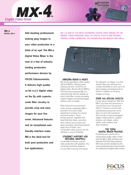
MX-4 DV切换台说明书
FUJITSU PRIMERGY CX400 M4 多節點伺服器说明书

Data SheetFUJITSU PRIMERGY CX400 M4 多節點伺服器專為工作負載設計的模組機架式電源FUJITSU PRIMERGY伺服器能執行任何工作負載與因應瞬息萬變的業務需求。
隨著業務拓展,對於應用的需求也隨之升高。
每項需求均需佔用資源,因此必須尋找能夠優化運算的方式,為使用者提供更佳服務。
PRIMERGY系統具備完整的產品組合,包含適用於遠端分公司的PRIMERGY直立式伺服器、萬用機架式伺服器,以及密度最佳化的多節點伺服器,有助於提升運算能力,配合業務需求。
經得起商業考驗的創新系列產品,以其高效率降低營運的成本與複雜程度,使日常運作更加靈活,並可無縫整合,助您專注在核心業務上。
FUJITSU PRIMERGY CX多節點系統是雲端、超融合式與高效能運算解決方案的理想平台,提供資料中心與分公司大量的運算效能,以執行虛擬化環境、複雜運算、伺服器整併及高可用性情境。
PRIMERGY CX400 M4FUJITSU PRIMERGY CX400 M4提供可擴充的IT架構,以其高度靈活性幫助企業及研究機構快速因應劇烈的挑戰。
CX400 M4為適用於FUJITSU多節點系統的模組機箱,結合類刀鋒伺服器的密度、效率,以及機架式伺服器的簡潔與成本優勢。
2U機箱使企業得以依照業務需求,逐步增加或移除至多4個節點。
此款機箱容許節點與組件共享電源、冷卻與管理資源,具備熱插拔與備援電源供應器、熱插拔與備援風扇模組,並可容納多達24顆儲存磁碟。
PRIMERGY CX伺服器節點提供虛擬桌面(VDI)、架構虛擬化、高效能與技術運算、網路服務、雲端運算,亦可作為超融合架構。
Fujitsu ServerView Suite簡化並自動化伺服器產品的週期管理,使IT運作更有效率。
全新ServerView ISM管理軟體可協助管理資料中心與融合架構內的各式硬體資源,並可整合進其他雲端管理系統,涵蓋伺服器、儲存、網路與設備元件管理。
4 CHANNELS DIGITAL VIDEO RECORDER 4 门数字录像机 说明书
USER MANUAL4 CHANNELS DIGITAL VIDEO RECORDER4门数字录像机使用手册为了正确的操作使用,请仔细阅读这本使用说明书。
为了达到本机器正常的使用以及最佳效能,请仔细阅读这本使用说明书。
使用者安装警语:美国联邦通讯委员会规章(FCC Compliance):您已被受权使用此通过美国联邦通讯委员所认证的设备,但您若未经过被授权的厂商并自行改变或修正本设备,将可能导致美国联邦通讯委员会规章无效(美国联邦通讯委员会规章第十五篇)。
免责声明:1. 本使用手册之内容,著作人不负任何明示或暗示之担保或保证责任。
2. 本使用手册虽然经过详细的校对,但仍有可能会发生错误,故恳请消费者及业界先进不吝赐教,以利本使用手册内容之正确及完整性。
警告,注意及版权说明警告z为避免火灾或电击危险,请勿将本机器使用或放置于潮湿或水气多的地方。
z请勿将任何物品放入或插入本机器的通气或散热孔。
注意1. 请勿将本机器置于高温,潮湿或多灰尘以及阳光直接照射的地方。
2. 避免危险请勿自行修理或更换零件。
此一位于四边行内的闪电标记系用来指示或警告使用者本机器内具有”危险电压”,若有任何磁性物质接近将可能导致电击的危险.此一位于四边行内的惊叹号标记则是用来指示或警告使用者需注意本手册所指示的操作或维护说明.使用者需自行确认当地政府所规范的影像或音源讯号,以避免触犯当地法规.版权说明本操作手册所使用或提及的商标系属于该公司所拥有的。
目录1介绍 (6)1.1特色 (6)1.2规格 (6)2硬件 (9)2.1前端按键面板 (9)2.2后端连接说明 (10)2.3前面板自动跳台、窗口缩放、PTZ、备份及随身碟信息按键进阶说明 (10)2.4摄影机及屏幕连接 (11)2.5外部警报连接 (11)2.6红外线遥控器 (13)2.7PTZ (PAN, TILT AND ZOOM) 摄影机 (14)3系统设定 (15)3.1使用者图形接口(GUI)架构图 (15)3.2实时画面显示暨弹出式选单说明 (17)3.3摄影机设定 (19)3.4位移侦测设定(MOTION SETUP) (21)3.5录像设定(RECORD SETUP) (22)3.6警报设定(ALARM SETUP) (25)3.7硬盘管理设定HARD DISK SETUP (25)3.8网络设定(NETWORK SETUP) (27)3.9备份设定(BACKUP SETUP) (29)3.10系统设定(SYSTEM SETUP) (33)4DVR 回放 (37)4.1时间回放 (38)4.2事件回放 (39)5备份回放 (40)5.1主画面设定 (40)5.2光盘备份回放 (44)5.3USB 与本地端备份及回放 (45)5.4备份影像至AVI (46)6网络远程浏览及回放 (47)6.1于PC端设定 IP 地址 (47)6.2选择性MICROSOFT INTERNET EXPLORER 浏览器设定 (49)6.3登录远程DVR (50)6.4远程操作功能 (51)6.5组态设定 (56)7.3GPP的应用与设定 (64)附录A:录像时间容量对照表(小时) (66)CIF (66)FIELD (67)附录B:HDD 相容列表 (68)附录C:错误讯息列表 (69)1 介绍1.1 特色z H.264 影像压缩格式。
MX系列调音台说明书
SVS MX系列调音台使用说明书适用于MX8/4Fx、MX10/4FX、MX14/4Fx导读目录:一、注意事项 (1)二、产品说明 (2)2.1声道控制部分 (2)2.2主控制部分 (4)2.3 连接器部分 (7)2.4设备连接 (8)2.5设备基本调试 (9)三、故障排除 (9)一、注意事项感谢您购买和使用本公司产品,为确保设备可靠使用及人身的安全,在安装、使用和维护时,请遵守以下事项:1、在设备安装时,应确保电源线中的地线接地良好,请勿使用两芯插头,确保设备的输入电源为220V/50Hz的交流电;2、如果对系统不熟悉,请咨询专业人士后再进行调试,以免误操作损坏机器;3、为防止火灾或漏电,不要将系统设备置于过冷或过热的地方,请勿将本机受雨或受潮,在阴雨或潮湿天气下如长时间不使用设备时,应拔掉设备电源插头;4、控制系统设备的电源在工作时会发热,因此要保持工作环境的良好通风,以免温度过高而损坏机器;5、非专业人士未经许可,请不要试图拆开设备机箱,不要私自维修,以免发生意外事故或加重设备的损坏程度。
二、产品说明以MX8/4Fx为例2.1声道控制部分○1-26dB衰减开关按下-26dB衰减开关时,表示该输入通道电平将衰减26dB。
○2○4GAIN增益控制旋钮GAIN增益控制将输入到调音台信号的输入电平调整到最佳水平。
为获得信噪比和动态范围之间的最佳平衡,请按照正规操作流程使用该旋钮。
○3PHONE/LINE通道选择开关输入通道选择转换,可选择莲花插孔输入或6.35mm TRS型插孔输入。
○5○6高中低音调节均衡器在下面所列的中心频率处对整个高频、中频和低频范围提供+/-15dB的控制。
当旋钮处于“0”位置时,频率响应将是平滑的。
○7AUX辅助输出旋钮控制从各路输入通道至AUX总线的信号电平。
若不使用AUX输出该旋钮置于最左边。
○8EFFECT效果控制旋钮控制从每个声道发送到EFFECT总线信号的电平。
JK Audio RemoteMix x4 4通道场地混音机用户指南说明书

JK AudioUser GuideRemoteMix x4™4 Channel Field Mixerii RemoteMix x4™ Field Mixer WelcomeCaution: To prevent possible hearing damage, avoid listening at high volume levels for long periods.RemoteMix x4 contains a headphone amplifier that is more powerfulthan the typical consumer product.JK Audio products are designed for the broadcast industry. Thebroadcast professional must be able to hear headphone signalsover the ambient noise level. From the cheering crowd at a footballgame to trackside at a car race, the program material or cues mustbe heard at high volumes without distortion.Road SafetyNever use headphones while driving or cycling, etc. It can bedangerous to turn up the volume even while walking. Doing so mayhinder your hearing and can be hazardous on the roadways or atpedestrian crossings.Handle with CareWhile RemoteMix x4 was designed to be very rugged and durable,it is not waterproof and care should be taken to keep the unit dry.Thank YouThank you for purchasing a JK Audio RemoteMix x4 Field Mixer. Please read this guide for instructions on setting up and using your new product.Getting AssistanceIf you have technical or application questions: Call us at:815-786-2929 Email us at:*******************Or check out our FAQ section for answers to common questions.Warnings & Safety Precautions• Read and keep these instructions.• Follow all instructions.• Clean only with a soft dry cloth.• Refer all servicing to qualified service personnel.•Heed all warningsContentsLimited WarrantyThe RemoteMix x4 is covered by a 1 year warranty to be free from defective workmanship and materials. To obtain service, contact JK Audio by phone oremail for return authorization. Once authorized, you will carefully pack and shipthe faulty product and all accessories to us. You will pay for shipping to us andwe will pay for return back to you.This warranty does not cover damages due to accident, weather, fire, flood, earthquake, misuse, unauthorized repairs or modifications, or damages occurredin shipping, only defective workmanship or materials.There are no expressed or implied warranties which extend beyond the warranty here made.Contents iiiFour Low Noise, High Headroom XLR Mic JacksMic/Line Switches on Channels 3 & 4 Individually switchable48v Phantom Power120 Hz Low Cut FilterMaster XLR Output 20 Hz – 20 kHz Four ¼” Headphone Jacks with Individual Source Selector and Level Controls ¼” Headphone Cue InputPhone Headset Interface with 3.5 mm TRRS Plug3.5 mm Send and Receive Jacks LED VU MeterHot-Swappable Dual 9-Volt Batteries 100-240 VAC External ACPower SupplyFeaturesUniversal Power supply with detachable cord 3.5 mm 4-conductor Wireless Interface CableIn the Boxiv RemoteMix x4™Field MixerOverviewIntroducing the RemoteMix x4™RMx4™ combines a four-channel field mixer with a four-channel headphone amplifier. After all, what good is a field mixer if you do not have a flexiblemonitoring capability for the whole crew?Great Sound – Four low-noise, high-headroom, active-balanced mic inputsfeature extremely high common mode rejection for outstanding cable noise immunity. High-Pass filter removes room rumble and mic handling noise. Directdrive DC coupled XLR output for improved output cable noise immunity. A softlimiter prevents over driving the full-duplex headset interface, while the masterXLR and 3.5 mm outputs are pre-limiter (full range).Convenience – 3.5 mm send and receive jacks for recording or playing back of recorded material. Separate headphone level and source selection controls foreach headphone output. Monitor just the clean mixer output, or the Cue inputplus the mix.Power Smart Design – Phantom power is not always needed, yet it can be areal drain on batteries. The phantom power generator only runs if any of therear panel 48V switches are set to “ON” position. Low noise, low power ICs areused throughout to preserve battery life. The 100-240 VAC desktop-style power supply (included) overrides the battery power only when the supply is actually providing power. If the power goes out, the batteries automatically cut in. Useone battery or two. The RMx4 is equipped with separate battery compartmentsfor hot swapping batteries.Radio/Podcast – RMx4 is designed for news, sports, and live remotes. Use it asa front-end mixer for your POTS, ISDN, IP or smart phone codec. XLR out, ¼”return to headphones.TV – RMx4 is designed for ENG, Sports, and interviews, with four ¼” headphone outputs. 3.5 mm TRRS provides 2-way IFB audio from your cell phone or notebook.AV/Conference – RMx4 is perfect for small press or hotel conferences.Rugged design for field use, runs > 10 hours on two hot-swappable 9-volt batteries. RMx4 will also route audio through cell phones or notebooks with the included 3.5 mm TRRS headset interface cable.1Overview2RemoteMix x4™ Field MixerGetting to Know Your RemoteMix x447652131. Mic Level ControlsEach of the four XLR inputs has a level control knob with a separate red <Peak> LED to indicate clipping on each channel. If you see more than an occasional flash of the <Peak> LED you should decrease the level for that channel.2. Master Level ControlThe <Master> control knob will set the overall level of the sum of all the mic and line inputs. The LED meter for the master audio level ranges from -30 dB to +3 dB.3. Headphone ControlsEach of the four headphone outputs has a separate level control and source selector so each listener can adjust their audio level independently. Monitor a mix of local mic and line inputs including the cue input or only the return audio from the Cue Input / Wireless Phone Interface without the local mix. 4. Cue ControlThe <Cue> input control adjusts the signal going to the headphones from the 1/4” <Cue Input>. When using the 1/4” Cue Input Wireless Interface, the individual headphone level control adjusts the overall level of your headphones while the <Cue> input control adjusts the level of the person on the other side of the call in all headphones. You should keep in mind that your wireless telephone also has level control. If you are having level problems that cannot be corrected with the controls on the RemoteMix x4, try adjusting the level on the wireless telephone itself.Controls & IndicatorsControls & Indicators 35. 120 Hz Low Cut FilterTurn on the Low Cut / High Pass filter to remove room rumble and mic handling noise.6. LED VU MeterRepresents the signal level of all four channels being sent to the<Master Output> and <Line Output>.7. PowerThis is the main power switch that turns the unit on. Whenever the power is turned on, the red LED above this switch will be lit. The green <AC> LED will be lit whenever a live AC power source is connected, even if the main power switch is off.RemoteMix x4 is powered by two 9 volt alkaline batteries located on the side of the unit. The red <Power> LED on the front of the device will gradually dim as the battery runs down, then extinguish about a half hour before the unit shuts down.These two batteries are in separate drawers and wired in parallel, you can hot swap one battery at a time so you never lose power.It is important to replace both at the same time with identical batteries. If two fresh batteries are not available, it is better to run using only one good battery. Since the battery fixtures are wired in parallel, it does not matter which one gets the single battery.Getting to Know Your RemoteMix x4Controls & Indicators Cont’d4RemoteMix x4™ Field Mixer Getting to Know Your RemoteMix x4786124351. Mic Inputs 1 and 2Balanced XLR jacks with low-noise pre-amplifiers.2. Mic Inputs 3 and 4Balanced XLR jacks with low-noise pre-amplifiers. A <Mic/Line> selector switch adds a 40 dB pad for a line level balanced input.3. Stereo 3.5 mm Line Level InputThe stereo 3.5 mm line level input can be used instead of or in addition to the channel 4 XLR input. You can connect either a mono or stereo signal to this mini jack. If you use a stereo input, both channels will immediately be summed together. Then the audio from the mini jack and the XLR would be added together and treated as one mono signal on channel 44. Stereo 3.5mm Line Level OutputCan be connected to your mini disk or other recording device. The<Master Output> will be on the Left channel and the Return mix from the <Cue input> on the Right channel.5. The Master OutputA balanced XLR jack that contains the sum of all four input XLRs and the3.5 mm input. This audio signal has a full 20 Hz to 20 kHz bandwidth.Inputs & OutputsInputs & Outputs Inputs & Outputs6. Cue Input / Wireless Phone InterfaceRemoteMix x4 comes equipped with a <Wireless Phone Interface> built in to the 1/4” <Cue Input>. This 1/4” wireless interface accepts a specially designed 1/4” to 3.5mm cable provided with the unit. This interface works with any wireless phone or notebook that accepts standard third partyheadsets and earpieces. Your product has been supplied with a 1/4” TRS to3.5mm TRRS interface cable. While the majority of current wireless phones use a 4 conductor, 3.5mm TRRS headset jack, some older phones use a2.5mm TRS headset jack. If your phone uses this smaller 2.5mm headset jack, you may contact our support department to request a compatible interface cable.When using the wireless interface, it is important to keep your wireless telephone 12” - 24” away from the RemoteMix x4 and any microphone or headphone cables. This will help prevent unwanted RF noise from entering the unit.7. Headphone JacksHeadphone output is determined by the source selector switch next to the Headphone Controls on the front.8. Power JackRemoteMix x4 is battery powered but we also provide a high quality, regulated AC to DC adapter to power RemoteMix x4 when AC power is available. Simply plug it into the back of RemoteMix x4 and plug the transformer into a wall outlet. This is a switching power supply so you can connect to a 110 or 220 VAC power source. When the power connector is inserted into the jack, the batteries are bypassed. The AC adapter does not charge the batteries. If you lose power during your broadcast, theRemoteMix 4 automatically reverts to battery power so your broadcast will not be interrupted.Make sure you use only the supplied AC power adapter with the RemoteMix x4. Using any other adapter could damage the unit.WARNING! It is strongly recommended that this product be connected to an adequate surge protection device.5Getting to Know Your RemoteMix x4FAQs1) How long will the batteries last in my RemoteMix x4?There are many variables that affect battery life, such as the number ofheadphones. All of our battery life tests included 4 headphones playing musicat average listening levels. These tests use standard alkaline batteries.Lithium batteries can add 3 to 4 times the battery life, at 3 to 4 times the cost.The following number is from lab tests and may not represent your usage:10hours using dynamic microphones.2) Will any cellular telephone work with RemoteMix x4?The wireless interface on the RemoteMix x4 works very well with mostcellular telephones. However, some wireless telephones generate excessiveRF noise which can be heard as a “chattering” or “motor boat” sound.The noise from these particular telephones will be unacceptable for mostbroadcast applications.RemoteMix x4 is supplied with a 1/4” TRS to 3.5mm TRRS interface cable.While the majority of current wireless phones use a 4 conductor, 3.5mmTRRS headset jack, some older phones use a 2.5mm TRS headset jack.If your phone uses this smaller 2.5mm headset jack, you may contact oursupport department to request a compatible interface cable.3) What kind of device can I connect to the Cue Input?Setting the switch for the dual-purpose 1/4” input to Cue Input will provide astandard line level input for connection to another audio device, such as aportable radio. The audio signal will be sent to all of the headphone outputs.This way, your announcers can listen for a cue from their radio station at theend of a station break.4) The cellular interface cable was left behind at our last event.Can I get a replacement at our local audio supply store?This is a custom made cable and is not wired the same as those that maybe available at your local electronics store. Please contact your JK Audiodealer or our Customer Service department and ask for a CN113 replacementcable. The CN113 has a 3.5 mm TRRS headset plug. Most newer phones,especially those that include a mp3 player, have a 3.5mm TRRS headset jackand therefore require the CN113 cable.5) The output from Mics 3 & 4 are very low but the other micsare fine.Check the position of the <Mic/Line> switch near Mics 3 & 4. This input canbe switched to accept a line level signal from a mixer or other equipment.6RemoteMix x4™Field MixerFAQs 6) How can I tell how much battery life is remaining?The red <Power> LED functions as a battery life gauge that will gradually dimas the battery runs down. This red LED will go completely dark about a halfhour before the unit shuts down. Keep in mind that the VU meter, Bluetooth,and clipping LEDs will remain bright until the unit stops functioning.7) Does the AC power supply charge the batteries?No. You may use rechargeable batteries, but you must remove and rechargethe batteries outside of the RemoteMix x4.8) I have lost my power supply for my RemoteMix x4 unit.Ihave a power supply that fits from a different product. Can Iuse this instead?No! Never use a power supply other than the one that was supplied by yourmanufacturer. Power supplies are available in either AC or DC output withmany combinations of voltage and available current. Most consumer powersupplies are not regulated. This could invariably damage your equipment,and also create a great deal of noise. Our products are designed for andtested with their respective power supplies for optimum operation. If youhave lost your power supply, please contact your JK Audio dealer or ourCustomer Service department and ask for a PS009 power supply for yourRemoteMix x4.FAQs78RemoteMix x4™ Field MixerTechnical InformationBlock DiagramX I n X I n X I n X I n 3.e r u tm o u th o n e o n e o n e o n e h o n e /u tTechnical Information Input Impedance / LevelFemale XLR (4) Mics:2k ohms / -25 dBu nomChannels 3 & 4 have a -40 dBu Mic/Line pad switch Line Level: 50k ohms / +20 dBu maxPhantom Power:48 VDC with 6.8k ohm supply resistance 1/8” (3.5mm) Stereo Line:20k ohms / -10 dBm nom Headphone Cue 1/4” Mono:20k ohms / -10 dBu nomOutputBalanced Male XLR:50 ohms / +16 dBu max, 20 Hz - 20 kHz, +/- 1dB, 0.04% THD @ +16 dBu1/8” (3.5mm) Stereo:100 ohms, -10 dBu nomHeadphone 1/4” Stereo:8 ohms / 1/3 watt per channelMisc.Power100-240 VAC, 50-60Hz or Two 9 VDC batteriesSize9.5” x 8” x 3” (24 x 20 x 8 cm)Weight 3.6 lbs (1.6 kg)SpecificationsTechnical Information9Declaration of Conformity FCC RegistrationManufacturer’s Name: Manufacturer’s Address:JK Audio, Inc.1311 E 6th Street Sandwich, Illinois 60548 USADeclares that the product:Product Name: Model Numbers:RemoteMix x4 Field Mixer RemoteMix x4Conforms to the following Product Specifications:Safety: ESD:AS/NZS 60950.1:2003CAN/CSA-C22.2 No. 60950-01-03UL Standard 60950-01 1st editionEN 55024:1998; EN 61000-3-2; EN 61000-3-3Emissions:EN 55022:1998AS/NZS CISPR 22 (2002)FCC Part 15, Subpart BICES-003EN 300 328FCC Part 15.247 FCC ID R47F2M03MLAIC Radio Standards RSS-210 Annex 8The product herewith complies with the requirements of the following Directives and carries the CE marking accordingly:LVD 2006/95/EC (Safety)R&TTE 1999/5/EC (Telecom)EMC 89/336/EEC (EMC)RoHS Directive 2015/863The Technical File containing supporting documentation is maintained at:JK Audio, Inc (Corporate Headquarters)Compliance Manager1311 E 6th StreetSandwich, Illinois 60548 USA815-786-2929 phone815-786-8502 fax10RemoteMix x4™Field MixerFCC Part 15 Compliance FCC RegistrationYour new JK Audio product has been registered with the Federal Communications Commission (FCC). This product complies with the standards in Part 68 of theFCC rules.FCC Part 15 Subpart A ComplianceThis equipment has been tested and found to comply with the limits for a Class Adigital device, pursuant to Part 15 of the FCC Rules. These limits are designed toprovide reasonable protection against harmful interference when the equipment is operated in a commercial environment. This equipment generates, uses, and canradiate radio frequency energy and, if not installed and used in accordance withthe instruction manual, may cause harmful interference to radio communications. Operation of this equipment in a residential area is likely to cause harmful interferencein which case the user will be required to correct the interference at his/her own expense.Changes or modifications not expressly approved by JK Audio can void the user’s authority to operate the equipment.FCC Complaince Notice11RemoteMix x4™Field MixerUser Guide Version 7/17/23JK Audio, Inc.220 Great Circle Road, Suite 114 Nashville, TN 37228United States815.786.2929© 2023 JK Audio, Inc. All rights reserved. JK Audio。
天地伟业48进8出矩阵切换控制器软件说明书

Warning Statements多媒体控制软件需要安装在硬盘录像机上,才能实现对矩阵主机的控制管理,本说明书以天地伟业硬盘录像机为例进行介绍。
本机的设计和制造充分考虑了安装人员、操作人员以及辅助设备的安全问题,但不正确的安装和使用也可能引起触电伤人或漏电失火,在安装本机时,须考虑下述情况:一、安装1、安装前请打开包装先根据配件清单,清点包装内的配件是否齐全,如有缺损请及时向厂家或供货商提出,以免由于缺损导致设备无法正常工作;2.产品的安装调试应由专业人员操作或在专业人员指导下进行;3、安装时请考虑安放位置的环境因素,注意防尘、防水,远离高温的热源和环境,避免阳光直接照射;4、为确保硬盘录像机正常散热,应避开通风不良的场所,切勿堵塞硬盘录像机的通风口,机箱后部设计有散热风扇,因此安装时其后部应距离其它设备或墙壁5cm以上;5、硬盘录像机应水平安装,避免安装在会剧烈震动的场所;6、第一次使用前请认真阅读说明书的快速入门部分,避免由于使用不当造成设备无法正常使用或损坏;7、切记不要尝试自己拆盖维修,以免造成设备损坏;8、请使用原厂配件或由制造商推荐的配件。
二、避免电击和失火1、切记勿用湿手触摸电源和硬盘录像机;2、勿将液体溅落在硬盘录像机上,以免造成机器内部短路或失火;3、勿将其它设备直接放置于硬盘录像机上部;4、当硬盘录像机的电源线与电源插座连接后,即使未启动,机器内部仍有电压,所以必须确保电源线与电源插座脱离后才可打开机箱盖。
三、运输与搬运1、本机的包装经过抗震设计和实验,搬运时,最好使用原来的包装材料和纸箱;2、运输装有硬盘的录像机时,务必将硬盘安装在硬盘架中,并用螺丝固定,否则可能会造成硬盘损伤而不能正常工作;3、避免在过冷、过热的场所间相互搬动录像机,以免机器内部产生结露,影响机器的使用寿命;4、严禁带电搬动本机,否则会损坏硬盘和主板。
四.特别注意:在使用时,我们特别提醒,硬盘录像机在带电状态下:1.不能直接插拔硬盘;2、不能直接插拔音视频线、串口线;3、不能直接带电插拔解码器、报警解码器及球型摄像机设备连线。
四通道数字录像机说明书

F E A T U R E S• Linear Zoom (2x~4x)• Multiplexer & Quad recording mode switching• Full size 30 frames/sec or Quad 120 frames/sec record• Support up to 250 GB HDD• Motion detection triggered record function• Wavelet compression format• 4 CH DVR replaces Time-Lapse VCR + Multiplexer / Quad• Picture-in-picture (PIP) & POP in live• Alarm input & output function• Video Loss Detection on each channel can record up to 256 events• Quick multiple search by date/time, alarm, full, motion list• Security password protection• RS-232, RS-485 communication protocolSEE W HAT Y OU’VE BEE N M I S S I N G S P E C I F I C A T I O N S©2005 Strategic Vista International Inc.As our product is subject to continuous improvement, SVII & subsidiaries reserve the right to modify product design, specifications & prices without notice and withoutincurring any obligation. E&OE3700 Koppers Street, Suite 100Baltimore, Maryland 21227,USA.Strategic Vista International Inc.300 Alden Road, Markham, Ontario L3R 4C1Canada.Video format:NTSC/EIA or PAL/CCIR Hard disk storage:IDE type, UDMA 66, supported over 250 GB HDDRecording mode:Manual / Alarm / Timer / Motion Camera Input Signal:Composite video signal 1 Vp-p 75Ω BNC, 4 channels Main Monitor Output:Composite video signal 1 Vp-p 75Ω BNCCall Monitor Output: Composite video signal 1 Vp-p 75Ω BNCMotion Detect Area: 16 * 12 targets per camera Motion Detect Sensitivity: 99 LevelsVideo Loss Detection:YesRefresh Rate:Up to 120 frames/sec. for NTSC / 100 frames/sec. for PAL Recording Rate:Up to 30 frames/sec. for NTSC / 25 frames/sec. for PAL Dwell Time:Programmable (1~15 Sec) Picture in Picture:Yes (Movable)Key Lock:YesPicture Zoom:2*2~4*4 (Movable) Camera Title:8 lettersVideo Adjustable:Hue/ Color/ Contrast/ Brightness AdjustableAlarm Input:TTL input, Hi (5V), Low (GND) Alarm Output:COM./N.O/N.C Remote Control:RS-232 or RS-485Time Display Format:YY/MM/DD, DD/MM/YY, MM/DD/YY, OFFPower Source:AC90-220V, 47Hz~63Hz Operation Temperature:10 ~ 40°CRS-232C / RS-485 (bps) :115200,57600,19200,9600,4800,3600,2400,1200Dimension (mm):343(W) x 223(H) x 59(D) Net Weight: 2.52 kgs。
三通道MPEG-4数字视频录像机系列说明书
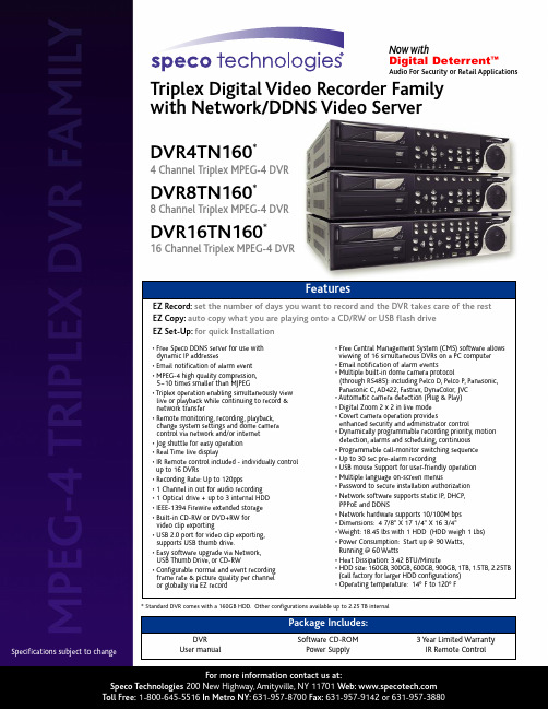
Triplex Digital Video Recorder Family with Network/DDNS Video ServerSpecifications subject tochangeFor more information contact us at:Speco Technologies 200New Highway,Amityville,NY 11701Web: Toll Free:1-800-645-5516In Metro NY :631-957-8700Fax:631-957-9142or 631-957-3880DVR4TN160*4Channel Triplex MPEG-4DVR DVR8TN160*8Channel Triplex MPEG-4DVRDVR16TN160*16Channel Triplex MPEG-4DVREZ Record:set the number of days you want to record and the DVR takes care of the rest EZ Copy:auto copy what you are playing onto a CD/RW or USB flash drive EZ Set-Up:for quick InstallationFeatures•Free Speco DDNS server for use with dynamic IP addresses•Email notification of alarm event •MPEG-4high quality compression,5~10times smaller than MJPEG•Triplex operation enabling simultaneously view live or playback while continuing to record &network transfer•Remote monitoring,recording,playback,change system settings and dome camera control via network and/or internet •Jog shuttle for easy operation •Real Time live display•IR Remote control included -individually control up to 16DVRs•Recording Rate:Up to 120pps•1Channel in out for audio recording •1Optical drive +up to 3internal HDD •IEEE-1394Firewire extended storage •Built-in CD-RW or DVD+RW for video clip exporting•USB 2.0port for video clip exporting,supports USB thumb drive.•Easy software upgrade via Network,USB Thumb Drive,or CD-RW•Configurable normal and event recording frame rate &picture quality per channel or globally via EZ record•Free Central Management System (CMS)software allows viewing of 16simultaneous DVRs on a PC computer •Email notification of alarm events•Multiple built-in dome camera protocol(through RS485):including Pelco D,Pelco P,Panasonic,Panasonic C,AD422,Fastrax,DynaColor,JVC •Automatic camera detection (Plug &Play)•Digital Zoom 2x 2in live mode •Covert camera operation providesenhanced security and administrator control•Dynamically programmable recording priority,motion detection,alarms and scheduling,continuous •Programmable call-monitor switching sequence •Up to 30sec pre-alarm recording•USB mouse Support for user-friendly operation •Multiple language on-screen menus•Password to secure installation authorization •Network software supports static IP,DHCP,PPPoE and DDNS•Network hardware supports 10/100M bps •Dimensions:47/8"X 171/4"X 163/4"•Weight:18.45lbs with 1HDD (HDD weigh 1Lbs)•Power Consumption:Start up @90Watts,Running @60Watts•Heat Dissipation:3.42BTU/Minute•HDD size:160GB,300GB,600GB,900GB,1TB,1.5TB,2.25TB (call factory for larger HDD configurations)•Operating temperature:14°F to 120°F*Standard DVR comes with a 160GB HDD.Other configurations available up to 2.25TB internalDVR User manualSoftware CD-ROM Power Supply3Year Limited Warranty IR Remote ControlPackage Includes:Now withDigital Deterrent ™Audio For Security or Retail ApplicationsFor more information contact us at:Speco Technologies200New Highway,Amityville,NY11701Web: Toll Free:1-800-645-5516In Metro NY:631-957-8700Fax:631-957-9142or631-957-3880。
Solecis 4K HDMI 数字切换器快速入门指南说明书
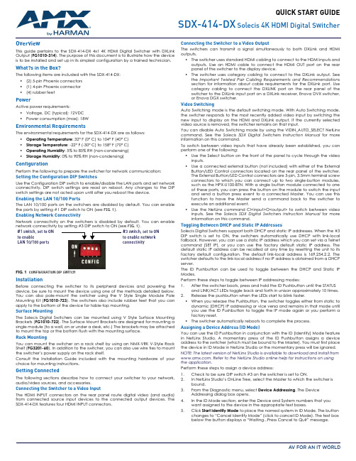
QUICK START GUIDESDX-414-DXSolecis 4K HDMI Digital SwitcherOverviewThis guide pertains to the SDX-414-DX 4x1 4K HDMI Digital Switcher with DXLinkOutput (FG1010-314). The purpose of this document is to illustrate how the deviceis to be installed and set up in its simplest configuration by a trained technician.What?s in the Box?The following items are included with the SDX-414-DX:•(2) 5-pin Phoenix connectors•(1) 4-pin Phoenix connector•(4) rubber feetPowerActive power requirements:•Voltage, DC (typical): 12VDC•Power consumption (max): 18WEnvironmental RequirementsThe environmental requirements for the SDX-414-DX are as follows:•Operating Temperature: 32° F (0° C) to 104° F (40° C)•Storage Temperature: -22° F (-30° C) to 158° F (70° C)•Operating Humidity: 5% to 85% RH (non-condensing)•Storage Humidity: 0% to 90% RH (non-condensing)ConfigurationPerform the following to prepare the switcher for network communication:Setting the Configuration DIP SwitchesUse the Configuration DIP switch to enable/disable the LAN ports and set networkconnectivity. DIP switch settings are read on reboot. Any changes to the DIPswitch settings are not acted upon until after you reboot the device.Enabling the LAN 10/100 PortsThe LAN 10/100 ports on the switchers are disabled by default. You can enablethe ports by setting #1 DIP switch to ON (see FIG.1).Enabling Network ConnectivityNetwork connectivity on the switchers is disabled by default. You can enablenetwork connectivity by setting #3 DIP switch to ON (see FIG.1).FIG. 1CONFIGURATION DIP SWITCHInstallationBefore connecting the switcher to its peripheral devices and powering thedevice, be sure to mount the device using one of the methods detailed below.You can also pole-mount the switcher using the V Style Single Module PoleMounting Kit (FG1010-723). The switchers also include rubber feet that you canapply to the bottom of the device for table-top mounting.Surface MountingThe Solecis Digital Switchers can be mounted using V Style Surface MountingBrackets (FG1010-722). The Surface Mount Brackets are designed for mounting asingle module (to a wall, on or under a desk, etc.) The brackets may be attachedto mount the top or the bottom flush with the mounting surface.Rack MountingYou can mount the switcher on a rack shelf by using an NMX-VRK V-Style RackShelf (FG3201-60). In addition to the switcher, you can also use wire ties to mountthe switcher’s power supply on the rack shelf.Consult the Installation Guide included with the mounting hardware of yourchoice for mounting instructions.Getting ConnectedThe following sections describe how to connect your switcher to your network,audio/video sources, and accessories.Connecting the Switcher to a Video InputThe HDMI INPUT connectors on the rear panel route digital video (and audio)from connected source input devices to the connected output devices. TheSDX-414-DX features four HDMI INPUT connectors.Connecting the Switcher to a Video OutputThe switchers can transmit a signal simultaneously to both DXLink and HDMIoutputs.•The switcher uses standard HDMI cabling to connect to the HDMI inputs andoutputs. Use an HDMI cable to connect the HDMI OUT port on the rearpanel of the switcher to the display device.•The switcher uses category cabling to connect to the DXLink output. Seethe Important Twisted Pair Cabling Requirements and Recommendationssection for information about cable requirements for the DXLink port. Usecategory cabling to connect the DXLINK port on the rear panel of theswitcher to the DXLink input port on a DXLink receiver, Enova DVX switcher,or Enova DGX switcher.Video SwitchingAuto Switching mode is the default switching mode. With Auto Switching mode,the switcher responds to the most recently added video input by switching thenew input to display on the HDMI and DXLink output. If the currently selectedvideo source is removed, the switcher remains on that input.You can disable Auto Switching mode by using the VIDIN_AUTO_SELECT NetLinxcommand. See the Solecis SDX Digital Switchers Instruction Manual for moreinformation on this command.To switch between video inputs that have already been established, you canperform one of the following:•Use the Select button on the front of the panel to cycle through the videoinputs.•Use a connected external button (not included) with either of the ExternalButton/LED Control connectors located on the rear panel of the switcher.The External Button/LED Control connectors are 5-pin, 3.5mm terminal screwconnectors to which you can connect up to two single-button modules,such as the HPX-U100-BTN. With a single button module connected to oneof these ports, you can press the button on the module to switch the inputand send a button press event to a connected Master. You can use thisfunction to have the Master send a command back to the switcher toexecute an additional event.•Use the NetLinx command CI<input>O<output> to switch between videoinputs. See the Solecis SDX Digital Switchers Instruction Manual for moreinformation on this command.Toggling Between DHCP and Static IP AddressesSolecis Digital Switchers support both DHCP and static IP addresses. When the #3DIP switch is set to ON, the switchers automatically use DHCP with link-localfallback. However, you can use a static IP address which you can set via a Telnetcommand (SET IP), or you can use the factory default static IP address. Thedefault static IP address can be recalled at any time by resetting the unit to itsfactory default configuration. The default link-local address is 169.254.2.2. Theswitcher defaults to the link-local address if no IP address is obtained from a DHCPserver.The ID Pushbutton can be used to toggle between the DHCP and Static IPModes.Perform these steps to toggle between IP addressing modes:1.After the switcher boots, press and hold the ID Pushbutton until the STATUSand LINK/ACT LEDs toggle back and forth in unison approximately 10 times.2.Release the pushbutton when the LEDs start to blink faster.•When you release the Pushbutton, the switcher toggles either from static todynamic (DHCP) IP addressing or vice versa and remains in that mode untilyou use the ID Pushbutton to toggle the IP mode again or you perform afactory reset.•The switcher automatically reboots to complete the process.Assigning a Device Address (ID Mode)You can use the ID Pushbutton in conjunction with the ID (Identify) Mode featurein NetLinx Studio. A momentary press of the ID Pushbutton assigns a deviceaddress to the switcher (which must be bound to the Master). You must first placethe device in ID Mode in NetLinx Studio or the momentary press will be ignored.NOTE: The latest version of NetLinx Studio is available to download and install from. Refer to the NetLinx Studio online help for instructions on usingthe application.Perform these steps to assign a device address:1.Check to be sure DIP switch #3 on the switcher is set to ON.2.In NetLinx Studio’s OnLine Tree, select the Master to which the switcher isbound.3.From the Diagnostic menu, select Device Addressing. The DeviceAddressing dialog box opens.4.In the ID Mode section, enter the Device and System numbers that youwant assigned to the device in the appropriate text boxes.5.Click Start Identify Mode to place the named system in ID Mode. The buttonchanges to “Cancel Identify Mode” (click to cancel ID Mode). The text boxbelow the button displays a “Waiting...Press Cancel to Quit” message.#1 switch, set to ONto enableLAN 10/100 ports#3 switch, set to ONto enable networkconnectivity© 2017 Harman. All rights reserved. Modero, AMX, AV FOR AN IT WORLD, HARMAN, and their respective logos are registered trademarks ofHARMAN. Oracle, Java and any other company or brand name referenced may be trademarks/registered trademarks of their respective companies.AMX does not assume responsibility for errors or omissions. AMX also reserves the right to alter specifications without prior notice at any time.The AMX Warranty and Return Policy and related documents can be viewed/downloaded at .3000 RESEARCH DRIVE, RICHARDSON, TX 75082 | 800.222.0193 | 469.624.8000 | +1.469.624.7400 | fax 469.624.7153AMX (UK) LTD, AMX by HARMAN - Unit C, Auster Road, Clifton Moor, York, YO30 4GD United Kingdom ? +44 1904-343-100 ? /eu/5081530 REV: CLast Revised: 12/01/2017NOTE: When in ID Mode, the entire system is put on hold while it waits for an event from any NetLinx device in the named system (e.g., pressing the ID Pushbutton on the switcher). The device that generates the first event is the device that will be “identified.”6.Briefly press and release the ID Pushbutton on the switcher. The switcher willexhibit the following behavior:•Respond with an ID Mode address response.•Report its old address offline.•Report its new address online.The Online Tree will refresh to display the new device address for the switcher.NOTE: NetLinx Studio (v3.3 or later) provides the ability to auto-increment IP Addresses and Hostnames as well as Device and System Numbers. Refer to the NetLinx Studio online help for details.Restore the Factory Firmware Image and Factory Default ParametersDuring power up – if you hold the ID Pushbutton until the STATUS andLINK/ACT LEDs toggle back and forth in unison approximately 30 times (10 slow,20 fast) and then release the pushbutton when the LEDs turn solid, the switcher’s factory firmware image will be restored. This procedure affects both the firmware version and the parameters.Perform these steps to restore the factory firmware image and factory default parameters:1.Press and hold the ID Pushbutton while plugging in the power connector.Start counting when the STATUS and LINK/ACT LEDs begin to flash in unison, not when the power connector is inserted.2.After the LEDs complete the following sequence, release the ID Pushbutton:•Once the switcher has started booting up, all LEDs flash in unison at the rateof once per second.•After 10 flashes at that rate, the LEDs will blink in unison at a faster rate.•After 10 seconds of flashing at the increased rate, all LEDs turn on solid.3.Upon release of the ID Pushbutton, the switcher executes the followingactions:•Restores itself to its factory firmware image.•Resets to factory default parameters 4.Once all actions in Step 3 are completed, the LEDs all turn off, indicating theswitcher is ready to reboot.The switcher automatically reboots to complete the process.Hardware InformationThis section lists important hardware information for the SDX-414-DX.Port NumbersDefault IP AddressesThe default IP addressing mode is DHCP.Important Twisted Pair Cabling Requirements and RecommendationsThe following requirements and recommendations apply to cabling DXLink (RJ-45) connectors:•DXLink cable runs require shielded category cable (STP) of Cat6 (or better).•DXLink twisted pair cable runs for DXLink equipment shall only be run withina common building.*•DXLink delivers 10.2 Gb/s throughput over shielded category cable. Basedon this bandwidth requirement, we recommend following industry standard practices designed for 10 Gigabit Ethernet when designing and installing the cable infrastructure.•The cables should be no longer than necessary to reach the endpoints. Werecommend terminating the cable to the actual distance required rather than leaving any excess cable in a service loop.For more details and helpful cabling information, reference the white paper titled "Cabling for Success with DXLink" available at or contact your AMX representative.* "Common building" is defined as: Where the walls of the structure(s) are physically connected and the structure(s) share a single ground reference.Additional DocumentationAdditional documentation for this device is available at . Refer to the Solecis SDX Digital Switchers Instruction Manual for additional details on installing, upgrading, and wiring the SDX-414-DX.You can also access this Quick Start Guide online by using your mobile device to scan the QR code located on the bottom of the SDX-414-DX.Port Port Number Address HDMI IN 11<DevID>:1:0HDMI IN 22<DevID>:2:0HDMI IN 33<DevID>:3:0HDMI IN 44<DevID>:4:0HDMI OUT 1<DevID>:1:0DXLINK OUT 1<DevID>:1:0External Buttons 14<DevID>:14:0AXLINK Keypad 115<DevID>:15:0AXLINK Keypad 217<DevID>:17:0Static IP Address 192.168.1.2Link-Local Address169.254.2.2。
4路视频分割矩阵切换器说明书

6、 Control I/O
3
控制接点说明: C1 至 C7 为常开,需要无源开关接点输入。 C1-按此开关为四画面显示,开机默认状态为四画面显示。 C2-按此开关为左二画面显示,显示视频输入 V1 和 V3 图像。 C3-按此开关为右二画面显示,显示视频输入 V2 和 V4 图像。 C4-按此开关为显示 V1 图像。 C5-按此开关为显示 V2 图像。 C6-按此开关为显示 V3 图像。 C7-按此开关为显示 V4 图像。 C8,C9,C10-为公共端。
NTSC:60 场/秒 NTSC:720 480
BNC 输入 输出
视频丢失报警,外部出发报警,移动侦测报警 全屏,电子放大,四分割,二分割,单画面 AC220V
0 0 -30 C -60 C
5
2
接口说明: 1、 Power In 2、 Power Out 220V/AC 输入接口。用于 4 路视频矩阵分割器供电。 220V/AC 输出接口。用于摄像机电源。
3、 V1-Out\ V2-Out\ V3-Out\ V4-Out 视频输出接口。用于接本地显示用 监视器。 4、 V1-In\ V2-In \ V3-In \ V4-In 视频输入接口。用于接摄像机 5、 MON Out 视频输出口。用于接监视器。 控制信号接口端子。
7、 电源输入法为:100-240V/AC 50-60HZ 交流电源。
三、外型结构与安装 1、外型尺寸:228*110*46mm 2、安装结构如下图:
4
四、技术规格
视频标准 解像度Байду номын сангаас视频输入 录像输入 录像输出 报警方式 视频输出方式 工作电压 环境温度
PAL:50 场/秒 PAL:720 576 1.0Vp-p75 1.0Vp-p75 1.0Vp-p75
DV说明书

• 摄录拍照同步:录像时,可按下模式切换键( 晶显示器屏幕上。
• 按回放键,观看所摄录像。 • 有4种影片分辨率:
影片质量
HD (720p30)
)抓拍图像。摄录拍照同步图标(
)将出现在液
WVGA60
VGA(4:3)
QVGA(4:3)
注意
• 录像时抓拍图像的清晰度与录像本身相同。
使用预录制功能
• 预录制功能能够保证使你不会错过任何录制机会。在按下“录制”键前,能多录制前3秒钟的电影。
右按钮: 补光照明灯开/数字补光开/关。 在录像菜单,按下转到子 菜单。 左按钮: 自拍定时器开/关。 在录像菜单,按下回到主菜单。 上按钮: LCD信息开/关。在选项之间移动。 下按钮: 删除当前或所有电影/图片。在选项之间移动。 设定钮:选项菜单开启。 确认设置。
远景按钮 : 放大。 广角按钮 : 缩小。 电源按钮: 按住一秒开启或关闭DV。
显示屏幕
2. 用手指拉动滚轮菜单,在选项分辨率、白平衡、场景、 效果和设置之间移动。
3. 在每个选项停止滚动时,会跳出子菜单。
4. 触摸屏幕以选择你要调整的特定选项,之后触摸[OK]以 确认设置。
5. 或触摸“返回”图标 ( )退出,但无任何改变。
6. 触摸屏幕上的 “ / ”以切换页面。
12
SC
录像分辨率
有4种影片分辨率。 • HD (720p 30): 录像分辨率为:1280x720p 30。 • WVGA 60: 录像分辨率为:848x480p 60。. • VGA(4:3): 录像分辨率为: 640x480p 30。 • QVGA (4:3): 录像分辨率为: 320x240p 30。
操作
1. 在录像模式,按 (屏幕上图标),显示滚轮 菜单。
全能机外置切换台使用说明

全能机外置控制面板使用手册北京中科大洋科技发展股份有限公司2017年7月版本说明版本创建时间版本号版本更新内容版本修改人20170620**苏大林目录一、产品简介 (4)二、主要流程 (4)三、切换台操作区域介绍 (4)四、安装、操作流程 (5)五、导播切换的使用方法: (9)六、外置控制面板尺寸图 (10)一、产品简介产品名称:大洋全能机外置切换台产品型号:ES-Switcher本产品通过USB或RS422与金时全能机主机进行控制通讯,支持双母线切换,快切、特技自动切、T杆切换方式。
支持DSK和字幕上下键,DDR、PPT、CG、图文播单播出控制。
支持真三维虚拟演播室的虚拟机位切换、轨迹、特技、摇臂等控制功能,以及对4路外来信号、网络、本地和PGM通道的调音功能。
可替代键鼠操作模式。
面板为水晶按键、RGB三色灯,金属面板、通讯接口USB、422,具有独立供电接口。
可嵌入桌面使用。
尺寸:长*宽*高(mm)415*173*高(最大53,最小35);桌面嵌入安装开口尺寸:长*宽*高(mm)383*146*40二、主要流程➢步骤1——先将切换台随机带的USB连接线与全能机连接。
➢步骤2——安装切换台驱动。
➢步骤3——在设备管理器下查看COM端口号。
➢步骤4——在全能机设置菜单下选择串口设置,选择相对应的COM端口。
➢步骤4——开始使用三、切换台操作区域介绍四、安装、操作流程1.将切换台USB线与全能机的USB2.0或3.0连接。
(如图)连线可使用USB2.0或3.0接口都可以。
远距离控制可以使用切换台上的422连接,注意采用此422连接要使用外接电源适配器供电。
2.打开“安装包下的\ftdi_ft232_drive文件夹”,点击打开“ft232r usb”文件夹,找到“CDM v2.08.30 WHQL Certified”安装程序。
(如图)3.点击“CDM v2.08.30 WHQL Certified”安装程序,安装切换台驱动。
专业矩阵切换器使用手册
User’s manual专业矩阵切换器使用手册Professional Matrix SeriesRev.1.2注意:●《专业矩阵切换器用户手册》以其中一个矩阵型号为例作为使用说明,并可作为其它型号的矩阵用户手册。
●本手册只作为用户操作指示,不作为维修服务用途。
●本手册是矩阵切换器的通用手册,实际使用可能会与本手册的内容有出入,这种情况将不属错漏,将根据实际情况另作书面说明。
安全操作指南为确保设备可靠使用及人员的安全,在安装,使用和维修时,请遵守以下事项:1.系统接地。
系统必须有完善的接地,否则,不仅造成讯号干扰,不稳定或机械损坏,而且还可能因漏电引起人身事故;请使用标准的三线电源插座,其地线接地电阻应小于1Ω。
2.禁止改变原设计。
禁止对本产品的机械和电器设计更改或增添任何部件。
否则。
本公司对由此所带来的后果不负责任。
3.请勿使用两芯插头,确保设备的输入电源为220V50Hz的交流电。
4.机器内有220V高压部件,请勿打开机壳,以免触电。
5.不要将机器置于过冷或过热的地方。
6.设备电源在工作时会发热,因此要确保工作环境的良好通风。
以免温度过高而损坏机器。
7.阴雨潮湿天气或长时间不用时,应关闭设备电源总闸。
8.在下列操作之前一定要将设备的交流电源线从交流供电电源插座拔下:a.取下或重装设备的任何部件。
b.断开或重接设备的任何电器插头或其它连接。
9.非专业人士未经许可,请不要拆开机箱,不要私自维修,以免发生意外事故或加重设备的损坏程度。
10.不要将任何化学品或液体洒在设备上或其附近。
目录一、产品简介 (5)1、关于DVI、RGB、VGA、AV、系列矩阵切换器 (5)2、矩阵的型号、规格 (8)3、信号输入,输出端口说明 (9)4、远端控制及通讯接口说明 (9)二、矩阵面板示意图及矩阵系统的安装 (9)1、矩阵前后面板示意图 (9)2、设备接线:a. RGBHV连接线 b. 音频连接线 (14)3、VGA/RGB长线驱动器的连接 (15)4、矩阵与控制电脑的连接 (15)三、前面板功能键 (16)1、切换指令 (16)2、UP、Down状态查询指令 (16)3、SAVE存储指令 (16)4、RECALL调用指令 (16)5、CANCEL键 (16)四、《MATRIX 2.01》矩阵控制软件 (17)五、R S232通讯协议 (21)六、产品技术参数 (23)一.产品简介1.1关于DVI系列矩阵切换器DVI矩阵切换器,是一款高性能的电脑信号专业切换设备,用于多个DVI电脑信号输入输出交叉切换,提供独立的DVI输入、输出端子,每路DVI分量信号单独传输、单独切换,使信号传输衰减降至最低,图像和声音信号能高保真输出。
AMX PR-0404 精确 4x4 4K60 HDMI 切换器快速起始指南说明书
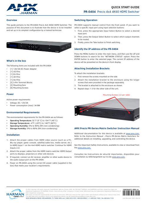
© 2021 Harman. All rights reserved. SmartScale, NetLinx, Enova, AMX, AV FOR AN IT WORLD, and HARMAN, and their respective logos areregistered trademarks of HARMAN. Oracle, Java and any other company or brand name referenced may be trademarks/registered trademarks of their respective companies.AMX does not assume responsibility for errors or omissions. AMX also reserves the right to alter specifications without prior notice at any time. The AMX Warranty and Return Policy and related documents can be viewed/downloaded at .3000 RESEARCH DRIVE, RICHARDSON, TX 75082 | 800.222.0193 | 469.624.8000 | +1.469.624.7400 | fax 469.624.71531000364571 REV: ALast Revised: 2021-06-24QUICK START GUIDEPR-0404 Precis 4x4 4K60 HDMI SwitcherOverviewThis guide pertains to the PR-0404 Precis 4x4 4K60 HDMI Switcher . The purpose of this document is to illustrate how the device is to be installedand set up in its simplest configuration by a trained technician.What’s in the boxThe following items are included with the PR-0404• [1] 12V/3A DC Power Adapter • [1] US Pins • [1] EU Pins • [1] UK Pins • [1] AU Pins• [5] 3-Pin Terminal Blocks • [2] Mounting Ears •[6] Mounting ScrewsPowerActive power requirements:• Voltage, DC: 12V/3A•Power consumption (max): 34.8WEnvironmental RequirementsThe environmental requirements for the PR-0404 are as follows: • Operating Temperature: 32˚F (0˚C) to 104˚F (40˚C)• Storage Temperature: -4°F (-20°C) to 140°F (60°C)• Operating Humidity: 5% to 90% (RH (non-condensing)•Storage Humidity: 5% to 90% (RH (non-condensing)Installation1. Attach the proper cables from HDMI video source (such as a PC,Blu-ray player , game console, satellite/cable box, media server , etc.) to HDMI Input 1 on the 4x4 HDMI matrix switcher . Continue for HDMI Inputs 2-4.2. Attach the proper cables from the HDMI matrix switcher HDMI Outputports to displays, projectors or other sink devices.3. If required, connect an AV receiver , amplifier or other audio device tothe audio output port on the PR-0404.4. Power on PR-0404 using the correct DC power cable (supplied in thebox) that meets your location’s requirements.Switching OperationPR-0404 supports manual control from the front panel. If you want to select a specific input port using input selection buttons:1. First, press the appropriate Input Select Button to select a desiredinput port.2. Then, press the Output Select Button to select which output channelsto be routed.3. Finally, press the Take button to finish switching.Identify the IP address of the PR-0404Press the MENU button to enter the main menu, and then use the UP and DOWN buttons to search for the “NETWORK STATUS” option. Press the ENTER button to enter the selected page. The current IP address of the device will be presented on the device’s front display.Attaching Installation BracketsTo attach the installation brackets:1. First remove the screws mounted on the side.2. Attach the installation bracket to the enclosure using the longerscrews that were provided in the package separately.3. The bracket is attached to the enclosure as shown.4.Repeat steps 1-3 for the other side of the unit.Mounting Screws (x3 per side)AMX Precis PR-Series Matrix Switcher Instruction ManualAdditional documentation for this device is available at . Refer to the Instruction Manual - Precis PR-Series Matrix Switchers for additional details on installing, upgrading, and controlling the device. See the Important Safety Instructions, available to view or download from the .Consultez les Instructions de sécurité importantes, disponibles pour consultation ou téléchargement sur le site .。
MIG-630系列切换台使用说明书-V1.0

非菜单状态介绍 ···························································································10 主菜单介绍 ···································································································11
商标信用·········································································································3 关亍软件·········································································································3 特性 ················································································································3
完备癿视频接口,包括 6 路 VGA 口,6 路 AV 口,4 路 DVI 口,1 路 SDI 扩展 口和 1 路数字信号扩展口,3 组信号输出接口,每组包括一路 DVI 和一路 VGA 输出,实现了多路模拟数字信号混合输入,多路模拟绍
FLIR MPX DVR 4HD 数字视频监控录像机说明书
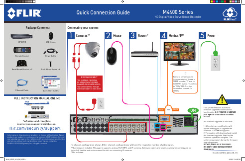
VGA* OR HDMI*
ON
Software and complete instruction manual available on:
f l i r. c o m / s e c u r i t y / s u p p o r t
Information in this document is subject to change without notice. As our products are subject to continuous improvement, FLIR Systems, Inc. and our subsidiaries reserve the right to modify product design, specifications and prices, without notice and without incurring any obligation. E&OE © 2015 FLIR Systems, Inc. All rights reserved.
If the system is beeping after startup, the Ethernet cable may not be connected or the system may not be connected to the Internet. To stop the beeping: 1. Connect an Ethernet cable from the system to your router and restart the system. OR 2. Right click and click Disable Beep.
NOTE: A constant Internet connection is required to use NTP
Arris MXv4 远程控制指南说明书
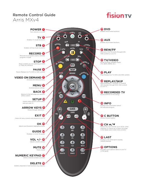
Scrolls through available inputs (TV, HDMI, HDMI2, etc.)
23 PLAY
Plays Replay/Live TV, DVR, and VOD content.
24 REPLAY/SKIP
Skips backward (7 seconds) or forward (30 seconds) through DVR, VOD content or Live TV
Moves through selections
EXIT 12
Clears all menu screens and returns to Live TV
OK 13
Selects and Deselects Highlighted items
GUIDE 14
Displays or closes the guide
VOL +/- 15
Adjusts volume control
MUTE 16
Mutes sound
NUMERIC KEYPAD 17
Enters channel numbers and text
DELETE 18
Deletes characters in text functions (e.g. Search)
MENU 8
Accesses device settings
BACK 9
Returns to the last page you were on within screens
SETUP 10
Used to enter remote control setup and sync with TV
SmartAVI FDX-M4P 多模光纤4端口DVI-D扩展器说明书

FDX‐M4P(FDX‐M4U)User ManualMULTIMODE FIBER OPTIC4 PORT DVI‐D EXTENDERQuad DVI-D, USB Keyboard, USB Mouse, RS-232 and Audio ExtenderTABLE OF CONTENTSWHAT'S IN THE BOX? 2INTRODUCTION 3FEATURES 3APPLICATIONS 3Why Fiber Optic?4 TECHNICAL SPECIFICATIONS5 HARDWARE INSTALLATION6 LIMITED WARRANTY STATEMENT7 WHAT'S IN THE BOX?FDX-TXM4P 1 Point to Point Quad DVI-D, USB Keyboard & Mouse, Audio and RS-232 Multimode Fiber Extender TransmitterFDX-RXM4P 1 Point to Point Quad DVI-D, USB Keyboard & Mouse, Audio and RS-232 Multimode Fiber Extender ReceiverCCPWR06 2 Power supply cord1 Quick Start GuideEN-SFX4P-EAR-P 4 Mounting BracketsFigure 2-1Figure 2-2INTRODUCTIONThe FDX-M4P consists of a transmitter and receiver that extend four DVI-D outputs, audio, USB keyboard, USB mouse and RS-232. For exceptional quality and security, fiber optic extension is the best solution. The FDX-M4P can go the distance with multi-mode fiber optic cabling that can reach up to 1,400 feet.FEATURES∙ Quad channel DVI-D, audio and USB keyboard and mouse with RS-232 control∙ Top Signal Quality over Multimode Fiber (up to 1,400 feet)∙ Video Resolutions up to 1920 x 1200 WUXGA at 60Hz∙ Customizable/Programmable DDC Table for Mac/PC∙ Supports all USB 2.0 and 1.1 Keyboards and Mice∙ Fiber Plug Type LC∙ Compatible With all Major KVM Switches∙ Supports Mac, PC, and Linux DVI∙ Uses universal DVI Single Link connectors∙ Zero pixel loss with TMDS signal correction∙ Rack Mountable Solution∙ Plug-and-playAPPLICATIONSMEDICAL FIELDIn the medical field where sensitive electronic devices are used, isolating workstation computers can be a matter of safety. The FDX-M4P allows the workstation computers to be housed in a central location, away from sensitive devices.INDUSTRIAL WORK AREASIn industrial work areas that may be too harsh for a workstation computer, the FDX-M4P can consolidate the computers into a safe location.SECURE COMPUTINGWhen it comes to security, the FDX-M4P is an excellent deployment option. With the FDX-M4P, devices can be centralized and secured from public access. This, combined with the intrinsic security of fiber op-tic cable, make the FDX-M4P one of the most secure KVM solutions available.INFORMATION KIOSKS/DISPLAYSAs with most information booths and kiosks, there is a risk of damage or theft. The FDX-M4P is the best way to secure computer hardware, by consolidating it to a secure location away from public access. FILM/MUSIC RECORDING STUDIOSWhen recording with sensitive cameras and microphones, computers are often too noisy to be used in the immediate vicinity. The FDX-M4P isolates the computers into another room, maintaining the silence that recording artists require.Why Fiber Optic?SmartAVI has created a full line of fiber optic extender products, understanding that this technology is su-perior to traditional cabling.Fiber optic cables are:∙ Capable of transmitting over very long distances with no signal loss.∙ Immune to electromagnetic interference. In situations where there is considerable interference, fiber optic cabling is the only solution.∙ Much more secure because they cannot be easily tapped. For this reason, military and law enforce-ment agencies use fiber optic cables for the transmission of sensitive data.∙ Relatively inexpensive and small enough to be routed through small spaces.What is the difference between Multi-mode and Single-mode Fiber?Multi-mode:Uses larger diameters allowing for high bandwidth over medium distances. Because of the multiple light paths or signals there is a higher chance of distortion or overlap of light signals over longer distances. Device-to-Matrix routing distance of 1,400 feet in multi-mode.Single-mode:Uses a narrower diameter that virtually eliminates distortion or signal overlap because there is only 1 sig-nal. This provides the least signal attenuation and provides transmission over much longer distances than Multi-mode. Device-to-Matrix routing distance of 15 miles in single-mode, 30 miles from device to device.This manual documents the FDX-M4P, a Multi-mode device. The FDX-S4P is Smart-AVI’s Single-Mode ver-sion.TECHNICAL SPECIFICATIONSResolution Up to 1920 x 1200 @60HzFormat DVI-D Single LinkInput Interface (4) DVI-D 29-pin femaleOutput Interface (4) DVI-D 29-pin femaleMaximum Pixel 165 MHzDDC InternalInput Equalization AutomaticInput Cable Length Up to 20 ft.Output Cable Up to 20 ft.Signal Type Stereo AudioInput Interface (1) 3.5 mm Stereo Audio FemaleOutput Interface (1) 3.5 mm Stereo Audio FemaleSignaling USB 2.0 or 1.1 (Keyboard and Mouse ONLY) Input Interface (1) USB Type B FemaleOutput Interface (2) USB Type A FemaleFiber Extender • 225m @ Multimode 62,5μ• 450m @ Multimode 50μFiber-Plug type LCPower Internal 110-240 VACDimensions 17" W x 5.75" D x 1.875" HWeight FDX-TXM4P 2.6 lbsWeight FDX-RXM4P 2.75 lbs.Operating Temp. 32-131°F (0-55 °C)Storage Temp. -4-185 °F (-20-85 °C)Humidity Up to 95% No CondensationRS-232 Data up to 115,200 bps, N,8,1, No Flow ControlHARDWARE INSTALLATION1. Turn off the computer, displays, speakers and any peripheral devices.2. Connect the USB cable, RS-232 cable and audio cable from the computer and to the FDX-TXM4P.3. Do not connect the DVI inputs from the computer to the FDX-TXM4P.4. Connect the DVI displays to the DVI connectors on the FDX-RXM4P. (DVI monitors recommended.)5. Connect USB mouse and keyboard to the USB connectors on the FDX-RXM4P.6. Connect speakers to the audio connector on the FDX-RXM4P.7. Connect an RS-232 device to the FDX-RXM4P.8. Connect the FDX-TXM4P to the FDX-RXM4P with multimode fiber-optic cables.9. Power on the computer, displays, speakers and any peripheral devices.10. C onnect the power cords and power on the FDX-TXM4P and the FDX-RXM4P. The status LEDs willflash. It will take up to 30 seconds for the FDX-M4P to learn the EDID settings from the connected DVI displays. Once the EDID settings are learned the LEDs will stop flashing.11. Connect the computer’s DVI inputs to the FDX-TXM4P.WARNING: Be careful not to cross the Video Link Fiber Optic cables. Video Link 1 on the FDX-TXM4P must be connected to Video Link 1 on the FDX-RXM4P. TX Video Link 2 must connect to RX Video Link 2 , 3 to 3, etc.Note: HDMI monitors with DVI to HDMI adapters may work with DVI EDID settings loaded.Figure 6‐1LIMITED WARRANTY STATEMENTA. Extent of limited warrantySmart‐AVI Technologies, Inc. warrants to the end‐user customers that the Smart‐AVI product specified above will be free from defects in materials and workmanship for the duration of 1 year, which duration begins on the date of purchase by the customer. Customer is responsible for maintaining proof of date of purchase.Smart‐AVI limited warranty covers only those defects which arise as a result of normal use of the product, and do not apply to any:a. Improper or inadequate maintenance or modificationsb. Operations outside product specificationsc. Mechanical abuse and exposure to severe conditionsIf Smart‐AVI receives, during applicable warranty period, a notice of defect, Smart‐AVI will at its discretion replace or repair defective product. If Smart‐AVI is unable to replace or repair defective product covered by the Smart‐AVI warranty within reasonable period of time, Smart‐AVI shall refund the cost of the product.Smart‐AVI shall have no obligation to repair, replace or refund unit until customer returns defective product to Smart‐AVI.Any replacement product could be new or like new, provided that it has functionality at least equal to that of the product being replaced.Smart‐AVI limited warranty is valid in any country where the covered product is distributed by Smart‐AVI.B. Limitations of warrantyTo the extant allowed by local law, neither Smart‐AVI nor its third party suppliers make any other warranty or condition of any kind whether expressed or implied with respect to the Smart‐AVI product, and specifically disclaim implied warranties or conditions of merchantability, satisfactory quality, and fitness for a particular purpose.C. Limitations of liabilityTo the extent allowed by local law the remedies provided in this warranty statement are the cus‐tomers sole and exclusive remedies.To the extant allowed by local law, except for the obligations specifically set forth in this warranty statement, in no event will Smart‐AVI or its third party suppliers be liable for direct, indirect, special, incidental, or con‐sequential damages whether based on contract, tort or any other legal theory and whether advised of the possibility of such damages.D. Local lawTo the extent that this warranty statement is inconsistent with local law, this warrantystatement shall be considered modified to be consistent with such law.NOTICEThe information contained in this document is subject to change without notice. SmartAVI makes no war‐ranty of any kind with regard to this material, including but not limited to, implied warranties of merchant‐ability and fitness for particular purpose. SmartAVI will not be liable for errors contained herein or for inci‐dental or consequential damages in connection with the furnishing, performance or use of this material. No part of this document may be photocopied, reproduced, or translated into another language without prior written consent from SmartAVI Technologies, Inc.20160901。
FOCUS Enhancements MX-4数字视频混音器说明书
APPLICATIONSM Live ProductionsM Sporting EventsM Business and classroom presentations M General video switchingM Weather chroma keyM Internet ProductionsM Linear EditingFEATURESM Integral graphics storeM Real-time 4-Layer Video Effects M S-video (Y/C), composite (RCA) inputs/outputsM 10-bit 4:2:2 video processing with superior input comb filter circuitry M Over 700 manual or automatic video transitionsM Store two frame or field freezes in memoryM RGB Color CorrectionM Eight GradientsM Built-in audio mixer with on-screen level metersM Dual Monitor Mode to allow the Preview screen to stay constant M Store 30 favorite transitions in a user-defined menuM Soft edges, colored borders and shadows for transitionsM Single and multiple picture-in-picture and movable mosaic maskM Learn feature memorizes a series of effects and multiple configurations M Preview four sources at once M Color generatorM Compose function creates a collage of still and/or moving picturesM Dual-field time base correction (TBC)M Input effects such as Chroma Key, Picture Flip, Strobe, Mosaic and more M GPI trigger inputM Houseblack inputM Ethernet I/O for computer & network connectivityM Color bar and black burst generators M Two year warrantyPRODUCT DESCRIPTIONThe MX-4 is a 10-bit, four-input video production switcher, mixer, frame synchronizer/TBC (Time Base Corrector), manual color corrector and special effects generator.MX-4™Digital Video Mixer MODEL MX-4Specifications subject to change without notice.All brand and product names are trademarks of their respective companies.©FOCUS Enhancements, Inc. MANL-0959-01SPECIFICATIONS General • Power Supply: External in-line; 110VAC@60Hz/240VAC@50 Hz universal • CE/FCC/UL/cUL approved (non-US/Canada versions meet local regulatory standards)• Dimensions: 16.6" x 9.5" x 3" (422m x 241mm x 76mm)• Weight:4 lbs. (1.8Kg)• Ambient temperature: 32-104°F (0-40°C)• Ambient humidity: Less than 95%Inputs •VIDEO:4 x S-video (Y/C): Y=1 Vp-p, C=0.30 Vp-p, 75-ohm,(4-pin mini-DIN connectors)4 x composite: 1.0 Vp-p 75-ohm, (RCA connectors)• Audio: 4 x 2 (L and R) RCA connectors, 50 k ohms • GPI: Mini-Jack Outputs •(PREVIEW and MAIN):1.0 Vp-p, 75 ohm; PREVIEW=1x RCA; MAIN=2x RCA Connectors and 2x S-Video (MAIN): Y=1.0 Vp-p, C=0.3 Vp-p; 75 ohm, 4-pin mini-DIN connector •Audio (L and R): 1 k ohms, RCA connectors •Headphone: Stereo jack, 8-100 ohms, stereo signal Effects •Video: 700+ Transitions: Input Effects including Strobe, Mosaic, Flips, Brightness, Color Saturation, Hue, Contrast, Black & White, Black & White Negative, Color Negative and Posterize, Special Effects including Chroma Key and Compose (see partial list under features)•Audio: Mix, fade, background Color Generators •Millions of colors Video Performance •Meets long-haul video broadcast specs including CCIR-601 sampling and RS-170A •Digital conversion: 13.5 MHz, 4:2:2, 10-bit quantization (Y/C); 10-bit quantization (composite)•Time base meets RS-170A standard •Compatible with all NTSC video sources and tape formats (PAL version available) •Unity gain •S/N Ratio: Greater than 60 dB (Y/C); Greater than 60 dB (composite)•Horizontal Resolution: 480 TV lines Audio Performance •Frequency response: Frequency response: 20 Hz-20 kHz, ±3 dB •S/N ratio: 80 dB Rear Panel DiagramConnection Y/C Video Audio Y/C Video GPI Outputs Info: 800 338-3348 Main: 408 866-8300 Fax: 408 866-4859email:******************Video Outputs。
- 1、下载文档前请自行甄别文档内容的完整性,平台不提供额外的编辑、内容补充、找答案等附加服务。
- 2、"仅部分预览"的文档,不可在线预览部分如存在完整性等问题,可反馈申请退款(可完整预览的文档不适用该条件!)。
- 3、如文档侵犯您的权益,请联系客服反馈,我们会尽快为您处理(人工客服工作时间:9:00-18:30)。
MX-4DV 多功能数字特技切换台
MX-4 DV快捷的10位4:2:2的数字质量视频、易于访问的图像库及特技效果,使之成为前期视频制作的最佳选择!
作为世界知名的高质量视频产品生产厂商,FOCUS Enhancements推出了业界领先的新一代产品--MX-4 DV™专业级多功能数字特技切换台。
这款产品带有四路IEEE-1394输入接口,实时预览,完整图像存储功能,可通过以太网接口与电脑或网络相连接,还拥有超过700种的特技效果,使之成为拥有终极性能的设备!
DV IS NOW
为了实现对视频源的灵活操控,通过12路视频源(4路S端子视频、4路复合视频与4路DV)之间的无缝切换,可使您的制作效率得到大幅提升。
额外增加的两个DV 接口,能够在制作设备上接收多路DV摄像机的视频信号,使您进行实时DV视频制作更加方便,使得您的数字视频图像自始至终完好无损。
完美的视、音频品质
FOCUS Enhancements 的实时10位(4:2:2)视频处理技术与出众的输入梳状滤波电路,保证MX-4 DV 输出的数字与模拟图像信号在质量上是丝毫无损的。
MX-4 DV 引以为傲的是它增强了音频同步混合能力,并且提供可在屏幕上显示的音量电平控制器。
这些优势与双重时基校正功能一起把MX-4 DV的视音频水准推升到了一个新的台阶。
附带预览功能
MX-4 DV 带有内罝预览功能,只需配一个监视器,便能同时预览四个输入视频信号,方便易用,更可节省大部分外罝预览设备成本。
完整的图像功能,使您如虎添翼
为了达到创造性表达的最终目的,您可以通过网络上传及时更新JPEG图片来增强
您的视频制作表现力。
MX-4 DV提供四层视频特技使您能够用JPEG图片作为一个输入信号、背景或前景图片。
前景图片可为预先设计好的字幕,在现场转播时可实时插入,实现简单标题字幕功能。
特技与特性
MX-4 DV内置700 种特技。
其中引入的一些新的转场特技、附加的四种输入特技、梯度与完整图像存储功能,可为您提供当今功能最为强大且兼具成本与效益的服务。
尤其强大的画中画功能,位罝、大少及形状均可调校,更可实现同时多画面功能。
输出前可先预览,确保输出无误。
超强抠像功能
支持多色层抠像(Chroma Key),在抠像时,能同时对不同颜色及不同的色彩深浅进行抠像,并且具有对抠像效果作预览显示的缓冲操作功能,确保抠像输出的安全性。
出众的性价比始终贯穿于出众的技术水平之上
FOCUS Enhancements利用最新的数字视频技术研发出一个完善的可带来空前收益的视频制作工具。
当您比较它的特点、性能与价格后,您就会发现MX-4 DV多功能数字视频特技切换台是目前市场上最物超所值的一款产品。
产品描述
MX-4 DV是一款带有十二路视频输入(四路DV,四路S端子、四路复合),10位?,四路视频输入切换台,混合器,帧同步器/TBC(时基校正器),色彩校正,完整图片存储与特技发生器。
应用:
现场制作
宗教与体育活动
商业与课堂演示
常规视频切换
Weather抠像
互联网视频制作
线性编辑
非线编DV信号处理
产品特点:
完整的图形库
实时四层视频特技
S端子、复合(RCA)信号输入/输出
IEEE 1394(火线,i-LINK)输入/输出
出众的输入梳状滤波电路的10位4:2:2视频处理技术
超过700种手动或自动视频转场特技
可将两帧或两个定格帧保存于内存中
RGB色彩校正
内建屏幕电平显示的音频混合器
支持四路或两路DV数字音频信号
双监视模式使得预览画面保持不变.
用户自定义菜单中可存储30种常用特技
支持边缘柔化、彩色边框与边框阴影等转场特技
支持单、多窗口画中画与可活动的掩饰马赛克
学习功能可记忆一连串的特技操作与组合设置
同时可预览四路视频源
色彩发生器
组图功能可利用静态和动态图片来生成拼图画面
内建双重时基校正器
支持抠色、图像翻转、画笔、马赛克等等特技
GPI触发输入
HouseBlack输入
支持以太网接口通过网络与电脑连接
内建彩条及黑场信号发生器
规格说明
概述:
•电源: 外部输入; 110V @60Hz /220V@50Hz 交流
经CE/FCC/UL/CSA 认证(除美国和加拿大以外的地区将会遵循当地标准) • 尺寸: 16.6" x 9.5" x 3"(422 mm x 241 mm x 76 mm)
• 重量: 4 lbs (1.8 kg)
• 环境温度: 摄氏0-40°C (华氏32-104°F)
• 环境湿度: 小于95%
模拟输入
• VIDEO: 4路S端子(Y/C): Y=1.0 Vp-p, C=0.30 Vp-p, 75Ω, (四针接口);
4 路复合:1.0 Vp-p 75Ω, (RCA 接口)
• Audio: 4 x 2 (L/R) 50KΩ, (RCA 接口)
• GPI: 迷你立体音插孔
• Houseblack
• 网络接口
模拟输出
• 视频, 主输出:
2 x S端子(Y/C):Y=1.0 V p-p, C=0.30 V p-p, 75Ω,(4针接口);
2x复合:1.0 Vp-p 75Ω,(RCA connectors)
• 预览: 1.0 Vp-p 75Ω,(RCA 接口)
• 音频: 1KΩ,2x (L/R)RCA 接口
• 头戴式耳机: 立体声, 8-100Ω,立体声信号
数字信号输入:
• 4路4针IEEE 1394 (火线, i.LINK)接口,包括音频/视频
数字信号输出:
• 主输出:1路4针IEEE 1394(火线, i.LINK) 接口,包括音频/视频
色彩生成器
• 百万种色彩
特技效果:
• 视频: 700多种转场. 输入特技包括:慢镜、马赛克、翻转、亮度调节、饱和度调节、对比度调节、色度调节与相片效果. 特殊的特技包括抠像功能与组图功能(详见产品特征下的部分列表)
• 音频: 混音、淡出淡入、背景音
视频性能:
数字信号
• D V标准采样: 13.5 MHz, 8位量化
• 水平分辨率: 500线
模拟信号
• 数字转换: 13.5 MHz, 4:2:2,
10位量化(Y/C);
• 增益: Unity
• 信噪比: 大于60 dB (Y/C);大于60 dB (复合信号)
• 水平分辨率: 480线
音频性能
数字双声道模式
• 采样: 16位, 48 kHz
• 频率响应: 20 Hz- 20 kHz
• 信噪比: 85 dB
数字4声道模式
• 采样: 12位, 32 kHz
• 频率响应: 20 Hz- 14.5 kHz
• 信噪比: 80 dB
模拟信号
• 频率响应: 20 Hz-20 kHz, ± 3 dB • 信噪比: 80 dB。
