SR-2201A单防区报警模块使用说明
JB-QBL-2100A型火灾报警控制器基本操作
JB-QBL-2100A型火灾报警控制器基本操作JB-QBL-2100A型火灾报警控制器基本操作1、开机状态:系统有电源输入(交流或备用电池)后,电源指示灯被点亮,系统自检运行,屏幕显示“系统运行正常”。
1)登录:值班员按下“面板键盘”键,弹出密码输入窗口,按“▲”或按“▼”键选择0-9数字,密码为0-9任一数字的四次重复,填好后,按“确认”键即可进入系统。
2)退出登录:在登录状态下,按下“面板键盘”键3)复位:当登录状态时,按下“恢复”键,系统将消除所有报警,并初始化全部输出。
4)隔离:A、按下“隔离”键,可以将当前处于报警状态(火警、反馈或故障状态)的所有总线设备隔离。
也可以进入操作系统选择“操作”菜单在下拉的菜单中选择“隔离当前报警”此时隔离当前报警设备。
注:面板上的“隔离”键仅隔离当前报警设备。
5)查询及取消隔离:a、进入操作系统选择“操作”菜单在下拉菜单中选择“查询当前隔离”菜单,此时屏幕上显示被隔离的设备。
b、进入操作系统选择“操作”菜单在下拉菜单中选择“取消全部隔离”,系统将取消隔离操作。
6)历史的查询:历史的查询包括火警、故障、请求/反馈、操作查询:a、历史火警:进入操作系统,选择“历史查询”菜单在下拉菜单中选择“历史火警”菜单,屏幕显示历史火警的内容。
b、历史故障:进入操作系统,选择“历史查询”菜单在下拉菜单中选择“历史故障”菜单,屏幕显示历史故障内容。
c、历史请求/反馈:进入操作系统,选择“历史查询”菜单在下拉菜单中选择“历史请求/反馈”菜单,屏幕显示历史请求/反馈的内容。
d、历史操作:进入操作系统,选择“历史查询”菜单在下拉菜单中选择“历史操作”菜单,屏幕显示历史操作的内容。
2、发生火警报警时的操作处理当有火警声和火警指示灯亮时,应立刻检查发生火警的部位,确认是否有火灾发生:若确认有火灾发生,应根据火情采取相应措施。
若为误报警,应采取如下措施:1)检查误报警部位是否灰尘过大、温度过高,确认是否是由于人为或其它因素造成误报警;2)按“恢复”键使控制器恢复正常状态,观察是否还会误报,如果仍然发生误报可将其隔离,并尽快通知安装单位或厂家进行维修。
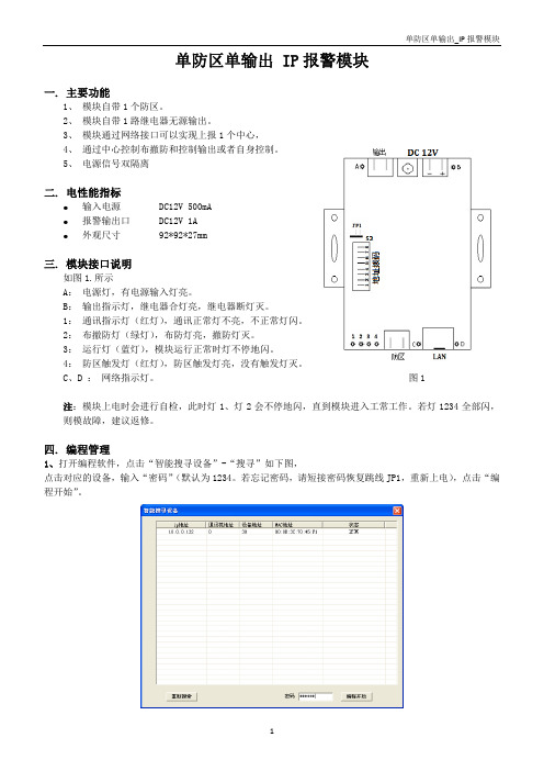
单防区单输出IP报警模块
1
单防区单输出_IP 报警模块
2、进入编程界面,可进行对应的编程的修改、保存、读取、查询、编程等操作。通过软件可查询到模块的布 撤防状态、防区是否触发,防区是否报警、输出的状态、模块与中心的通讯状态、设备状态等等,如完成编程 或查询后,点击“编程生效”退出。
3、编程应该举例,把“中心 IP 地址”修改为“192.168.1.123”。 (1)、 在功能码下拉中选中“1-1.IP 设置”,再在主码中选
4
码 0 动态 IP 支持 0 模块 IP 支持
编程 位数
1 15
出厂缺省值
1 10.0.0.123
0 网关
15 10.0.0.1
0 网络掩码
15 255.255.255.0
0 中心 IP 地址
15 10.0.0.31
0 目的 UDP 端口
6 3080
0 源 UDP 端口
6 3080
0 在线上报时间
4 10
地址编码开关说明 ● 地址编码通过地址拨码开关S2进行设置,地址编码采用2进制编码方式。 ● 编码开关按“12345678”顺序排列设置二进制地址。
例如:某设备的编码为13;对应的位二进制数为:00001101,在地址拨码开关对应的顺序为1-8(即高位 为1,低位为8),1,2,3,4,7位不动, 5,6,8位拨到”ON”一边。 ● 在拨码开关上, "ON"一边表示"1", 对应表格中的 "●"; 在"OFF"一边表示"0"。
(5)、 上述操作已完成对“中心 IP 地址”的编程,
2
此时用户可点击“读取编程值”来检验是否配置正确。 查询如下图所示。
(6)、 编程完成后,用户点击“编程生效”让模块重启,此 时模块将会更新配置数据,采用新的配置运行。
SH22A报警控制器简单操作说明
SH22A报警控制器简单操作说明SH2112A报警控制器是一款用于安全防护和报警控制的设备,适用于住宅、商业和工业场所。
它可以与各种安全传感器和控制设备连接,例如门磁、烟雾探测器、红外线探测器等。
本文将简单介绍SH2112A报警控制器的基本操作。
一、基本信息设置1.连接电源:将控制器连接到适配器,并将适配器连接到电源插座。
2.网络连接:通过网线将控制器连接到局域网中。
3.设置IP地址:可以通过工具软件设置控制器的IP地址,确保在同一局域网中的其他设备可以与控制器通信。
二、添加传感器设备1.添加传感器:将传感器设备的信号线连接到控制器的对应输入端子上。
2.确认输入模式:根据传感器的类型,可以在控制器的设置中选择不同的输入模式,并设置传感器的工作参数。
三、设置报警规则1.报警阈值设置:根据实际需要,设置传感器触发报警的阈值。
例如,设置烟雾传感器的阈值为50,当检测到的烟雾浓度超过50时触发报警。
2.报警联动设置:可以根据需要设置传感器报警时的联动动作,例如触发报警时,控制器可以自动触发警报器、录像设备等。
四、报警处理1.报警提示:当传感器触发报警时,控制器会发出声音和闪灯提示,并在控制器的显示屏上显示报警信息。
可以通过控制器的按钮或遥控器进行报警确认或静音处理。
2.远程报警通知:控制器可以通过网络发送报警通知,例如发送邮件或短信给指定的用户,实现远程报警处理。
五、管理维护1.网络管理:可以通过网络远程访问控制器进行参数设置和监控状态。
2.数据备份:可以定期备份控制器中的报警记录和设置参数,以便在需要时恢复。
3.定期检测设备:定期检查和维护连到控制器上的传感器设备,保证其正常工作。
总结:通过以上的操作,就可以完成对SH2112A报警控制器的简单操作。
首先需要设置基本信息,例如连接电源和网络设置。
然后添加传感器设备,并设置传感器的工作参数。
接下来设置报警规则,包括报警阈值和报警联动设置。
当传感器触发报警时,控制器会进行相应的报警处理,包括声音和闪灯提示,以及远程报警通知。
单防区单输出总线通信模块 AW-BIX01 安装说明
AW-BIX01是连接在AW-BM1600大型总线报警主机扩充总线上使用的总线通信扩充模块,提供1个标准接线防区输入和一路集电极开路输出,输出端口可通过编程设定自身联动输出(即对应本身的输入防区实现报警联动)和外部控制输出两种工作模式,外部控制支持手动命令控制输出和可编程的报警联动输出控制模式。
其很小的体积足以直接放置在某些体积较大的探测器中,因此AW-BIX01更加适合在防区比较分散又需要一一对应进行现场联动的报警系统中使用。
另外,AW-BIX01使用和维护简单方便,只需通过拨码开关设置一个485地址接入总线系统中即可使用。
主要性能工作电源:直流10-28V,具备反极性保护工作电流:约20mA防区输入:1个带2K线末电阻标准接线防区防区类型:包括出入口、防拆、内部、周边、煤气、火警锁匙布撤防、24小时无声紧急、24小时有声紧急防区监控保护:2KΩ±30%线末监控电阻联动输出:单路集电极开路输出(驱动能力不大于200mA),实现一一对应现场联动通信接口:两线485总线通信接口通讯协议格式:MODBUS工业控制器网络通信协议485地址方式:六位拨码开关485地址范围:01~62LED通信状态指示体积小,可放置在某些探测器内无需编程,在主机中登记后即可使用工业级芯片,可适合户外使用支持防区旁路功能硬件看门狗功能防雷保护措施工作温度:-20ºC~50°C工作湿度:不大于90%,非凝露外形尺寸:60mm X 20mm警告:通电前一定要确保输出端不可裸露,否则容易导致输出短路而使内部电路永久损坏。
模块与管理主机接线规范请参照管理主机安装说明的相关章节。
附:485地址拨码表地址拨码 1 2 3 4 5 678910111213 14 15 1617181920211 On Off On off On Off On Off On Off On0ff0n 0ff 0n 0ff On Off On off On2 Off On On Off Off On On Off Off On On0ff0ff On 0n 0ff Off On On Off Off3 Off Off Off On On On On Off Off Off Off0n0n 0n 0n 0ff Off Off Off On On4 Off Off Off Off Off Off Off On On On On On0n 0n 0n 0ff Off Off Off Off Off5 Off 0ff Off Off Off Off Off Off Off Off Off0ff0ff 0ff 0ff 0n0n0n0n0n0n6 Off 0ff 0ff 0ff 0ff 0ff0ff0ff0ff0ff0ff0ff0ff 0ff 0ff 0ff Off0ff0ff0ff0ff 拨码22 23 24 26 26 2728293031323334 35 36 3738394041421 Off On Off On Off On0ff0n0ff0n0ff On Off On off On Off On Off On Off2 On On Off Off On On0ff0ff On0n0ff Off On On Off Off On On Off Off On3 On On Off Off Off Off0n0n0n0n0ff Off Off Off On On On On Off Off Off4 Off Off On On On On On0n0n0n0ff Off Off Off Off Off Off Off On On On5 0n 0n 0n 0n 0n 0n0n0n0n0n0ff Off0ff Off Off Off Off Off Off Off Off6 0ff 0ff 0ff 0ff 0ff 0ff0ff0ff0ff0ff0n On0n 0n 0n 0n0n0n0n0n0n 拨码43 44 45 46 47 4849505152535455 56 57 5859606162631 On 0ff 0n 0ff 0n 0ff On Off On off On Off On Off On Off On0ff0n0ff0n2 On 0ff 0ff On 0n 0ff Off On On Off Off On On Off Off On On0ff0ff On0n3 Off 0n 0n 0n 0n 0ff Off Off Off On On On On Off Off Off Off0n0n0n0n4 On On 0n 0n 0n 0ff Off Off Off Off Off Off Off On On On On On0n0n0n5 Off 0ff 0ff 0ff 0ff 0n On On On On On On On On On On On On On On On6 0n 0n 0n 0n 0n 0n On0n0n0n0n0n0n 0n 0n 0n0n0n0n0n0n。
狮岛2011年8月第2版

四 、JB-QG-SD2200数字式智能火灾报警及联动控制系统(柜式机箱) 60cm× 185cm× 40cm(宽× 高× 厚)柜式机箱,10.4吋彩色液晶显示。热敏式打印机、总线产品为电子编码,总线地址混编 1 2 3 4 5 6 火灾报警控制器(联动型) 火灾报警控制器(联动型) 火灾报警控制器(联动型) 火灾报警控制器(联动型) 火灾报警控制器(联动型) 火灾报警控制器(联动型) SD2200-250 SD2200-500 SD2200-750 SD2200-1000 SD2200-1250 SD2200-1500 102000.00 1个I/O子站,1×250点 106000.00 2个I/O子站,2×250点 110000.00 3个I/O子站,3×250点 114000.00 4个I/O子站,4×250点 118000.00 5个I/O子站,5×250点 122000.00 6个I/O子站,6×250点 -2本报价包含:标准机柜、SD7014A (DW)系统电源。 本报价不包含联动子站、键盘子站 、系统备电、联动电源和备电等 本报价包含:标准机柜、SD7014A (DW)系统电源。 本报价不包含联动子站、键盘子站 、联动电源和备电等
-3-
SHIDAO FIRE
产
2007年8月启用
序号 32 33 34 35 36 37 38 39 40 41 42 43 44 45 46 47 48 49 50 51 52 53 54 55 56 产 品 名 称 火灾报警控制器(联动型) 火灾报警控制器(联动型) 火灾报警控制器(联动型) 火灾报警控制器(联动型) 火灾报警控制器(联动型) 火灾报警控制器(联动型) 火灾报警控制器(联动型) 火灾报警控制器(联动型) 火灾报警控制器(联动型) 火灾报警控制器(联动型) 火灾报警控制器(联动型) 火灾报警控制器(联动型) 火灾报警控制器(联动型) 火灾报警控制器(联动型) 火灾报警控制器(联动型) 火灾报警控制器(联动型) 火灾报警控制器(联动型) 火灾报警控制器(联动型) 火灾报警控制器(联动型) 火灾报警控制器(联动型) 火灾报警控制器(联动型) 火灾报警控制器(联动型) 火灾报警控制器(联动型) 火灾报警控制器(联动型) 火灾报警控制器(联动型) 型 号 规 格 SD2200-8000 SD2200-8250 SD2200-8500 SD2200-8750 SD2200-9000 SD2200-9250 SD2200-9500 SD2200-9750 SD2200-10000 SD2200-10250 SD2200-10500 SD2200-10750 SD2200-11000 SD2200-11250 SD2200-11500 SD2200-11750 SD2200-12000 SD2200-12250 SD2200-12500 SD2200-12750 SD2200-13000 SD2200-13250 SD2200-13500 SD2200-13750 SD2200-14000
A1201单防区模块使用说明书
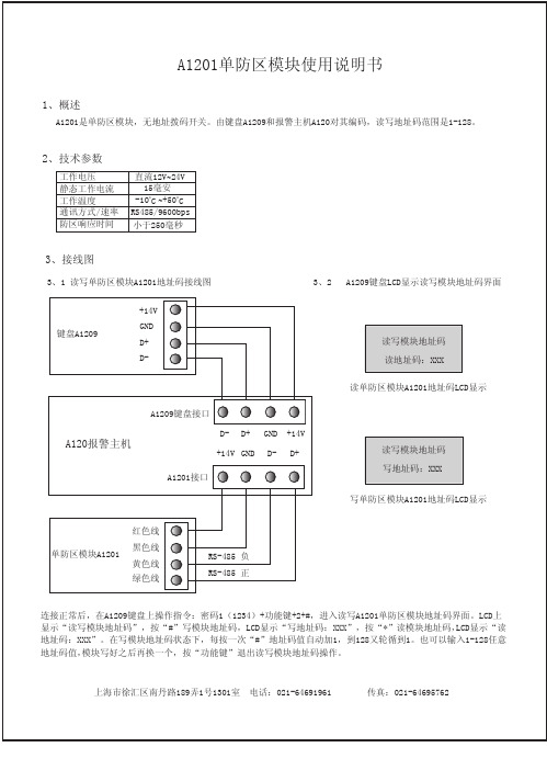
5、故障分析
5、1 单防区模块A1201接到系统主机A120巡检总线的任何一路,键盘A1209的LCD显示“模块离线:XXX”。 1:首先判断此模块的“地址码”是否超出系统模块总数范围。 2:检查线路是否正常,若线路正常,再判断此模块地址码和实际地址码是否一致。 3:检查系统中是否有和此模块“地址码”重复模块。
防区公共线
3、4 单防区模块A1201防区和探测器接线图
常闭接法 电源+
地 常闭(NC) 公共(COM)
2.2k
ZONE1(防区) A1201
C(防区公共)
探测器
常开接法 电源+
地 常开(NO) 公共(COM)
探测器
2.2k
ZONE1(防区) A1201
C(防区公共)
4、操作方法
4、1 当单防区模块的地址码都编写好之后,对系统编程,在键盘A1209上操作指令进入编程:用户1(密码)+*+#, 菜单的第一项显示“设置模块总数”,LCD屏幕显示模块总数:XXX。光标在哪个数字闪烁即可输入修改,输入 系统中最大的单防区模块地址码值即可。
3、接线图
3、1 读写单防区模块A1201地址码接线图
3、2 A1209键盘LCD显示读写模块地址码界面
键盘A1209
+14V GND D+ D-
读写模块地址码 读地址码:XXX
读单防区模块A1201地址码L+ GND +14V +14V GND D- D+
5、接32路继电器输出模块A1232B 用随机配件IDC-40芯扁平电缆线将A1232A和32路继电器输出模块A1232B连接即可。
地址编码开关 1、2、3、4(OFF、OFF、OFF、OFF) 1、2、3、4(OFF、OFF、OFF、OFF) 1、2、3、4(OFF、OFF、OFF、OFF) 1、2、3、4(OFF、OFF、OFF、OFF)
电源防雷模块安装说明
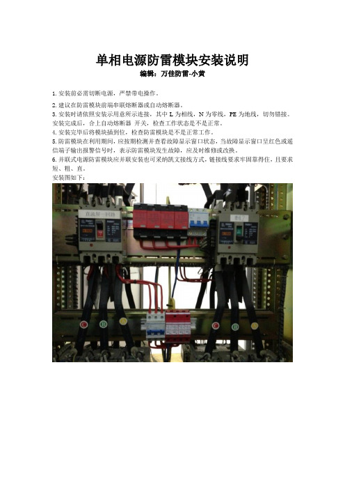
单相电源防雷模块安装说明
编辑:万佳防雷-小黄
1.安装前必需切断电源,严禁带电操作。
2.建议在防雷模块前端串联熔断器或自动熔断器。
3.安装时请依照安装示用意所示连接,其中L为相线,N为零线,PE为地线,切勿错接。
安装完成后,合上自动熔断器开关,检查工作状态是不是正常。
4.安装完毕后将模块插到位,检查防雷模块是不是正常工作。
5.防雷模块在利用期间,应按期检测并查看故障显示窗口状态,当故障显示窗口呈红色或遥信端子输出报警信号时,表示防雷模块发生故障,应及时维修或改换。
6.并联式电源防雷模块应并联安装也可采纳凯文接线方式,链接线要求牢固靠得住,且要求短、粗、直。
安装图如下:。
Sensata 1 SC20-ALM 循环电流保护隔离电流放大器安装和操作指南说明书

SC20-ALMLOOP POWERED ISOLATING TRIP AMPLIFIERSafe Installation and Operation GuideCAUTION:This equipment is designed for possible connection to mains voltages (110V ac relay version) and must be used in accordance with this guide. If it is not, the safety protection provided by the equipment may be impaired.This equipment relies on double/reinforced insulation for safety and does not require a protective earth.Whilst every effort has been taken to ensure the accuracy of this document, we accept no responsibility for damage, injury, loss or expense resulting from errors or omissions, and reserve the right of amendment without notice. This document may not be reproduced in any way without the prior writtenpermission of the company.AUG 2022CONTENTS3 INTRODUCTION Page 15ANDINSPECTION Page UNPACKING23 WIRING CONNECTIONS ANDINSTALLATION Page 56 CONNECTIONS Page3.13.2 NOTES ON PROCESS INPUTS ANDOUTPUTS Page 63.37 INSTALLATION Page7 4OPERATION Page 5ELECTRICAL AND ENVIRONMENTAL8 SPECIFICATION Page5.1 POWER SUPPLY AND INSTALLATION8 CATEGORY Page5.2 ENVIRONMENTAL CONDITIONS Page 85.3 COMPLIANCE WITH EUROPEANCOMMISSION DIRECTIVES Page 81 INTRODUCTIONThis unit is intended to accept a 4-20mA current signal and provide a single pole normally open solid state relay contact output.An internal switch is used to select contact closure either above or below a set point which can be adjusted by a 20 turn front panel potentiometer and measured with a voltmeter.The power for the device is derived from the 4-20mA input loop.IMPORTANT Two different relay output options exist on the SC20-ALM:a) NB24V ac/dc @ 300mAVoltages above 100V peak will destroy the relay. The use of freewheel/clamp diodes across the coils of external relays and other inductive loads is recommended.b)110/115V ac @ 130mANB The 110V rated output is internally protected against over voltages up to 500V and no external clamp devices will generally be necessary. This relay type will not work with dc loads.4-20mA LOOP INPUTBLOCK DIAGRAM: 24V ac/dc RELAY VERSION4-20mA LOOP INPUTMAINS SAFETY ISOLATION (115V ac only, not 230V ac)2 UNPACKING AND INSPECTIONPlease inspect the instrument carefully for signs of shipping damage. The unit is packaged to givemaximum protection but we cannot guarantee that mishandling will not have damaged the instrument. In the case of this unlikely event: i)Do not use the instrument - physical damage may have compromised the safety insulation.ii)Please contact your supplier immediately and retain the packaging for subsequent inspection.Assuming the unit is undamaged please check the side label as follows:On one side of the enclosure you will find the serial number label, example of which is shown below:Please check that all the parameters are correct, especially, the Relay Rating.3 WIRING CONNECTIONS AND INSTALLATIONOn the front panel label you will find the connection details for the 4-20 mA loop input and relay contacts.Please study this carefully to ensure that the unit will be wired correctly. In particular please note the following; especially in the case of the 110V ac relay option:This symbol indicates that the unit is of Class IIconstruction - i.e. it provides double insulationbetween relay contacts and 4-20mA input wiringinside the enclosure. It is up to the installer topreserve this level of insulation outside the unit.This symbol means CAUTION! refer to this guide.It is recommended that bootlace ferrules are used on all wiring terminations. In any case the maximum terminal torque of 0.4Nm must not be exceeded. If it is the resulting damage to the terminal blocks and internal connections could compromise the integrity of the safety insulation. If in doubt get asmaller screwdriver.3.1 CONNECTIONSIN- 4-20mAInput -veIN+ 4-20mA Input +veOUT-Relay Output -ve OUT+Relay Output +ve The conductor of the 4-20mA loop which is normally at a more -ve potential.The conductor of the 4-20mA loop which is normally at a more +ve potential.Relay output contacts. Polarity is unimportant.Relay output contacts. Polarity is unimportant.3.2 NOTES ON PROCESS INPUTS AND OUTPUTSa)Operational CAUTION!The input is protected to a current of 30mA. The input will be damagedby application of any voltage source which is not limited to or fixed atless than 30 mA.See Section 1 of this guide for comments regarding the protection of therelay output.b)Safety The input circuit is classed as Separated Extra Low Voltage (SELV). Thismeans that it must not be externally connected to voltages exceeding 30V ac or60V dc, nor does it generate voltages above these limits internally.For the 110/115V ac relay version the output circuit is classed as hazardous liveand must be treated accordingly.3.3 INSTALLATION (and removal)4 The 20-ALM unit clips directly onto ‘Top Hat’ (TS35) symmetrical DIN rail or TS32 asymmetricalG-rail. Mounting orientation is not important. Ensure ambient temperature is below 55o C.NOTE: Good airflow around the unit will maximize reliability.The use of bootlace ferrules is recommended on wiring terminations.Do not exceed terminal torque rating of 0.4 Nm - Use an appropriate screwdriver.This unit can be removed from the DIN rail by gently levering the protrusion on the DIN rail clip up from the top of the rail (assuming unit is mounted vertically and upright) with a small screwdriver and lifting the top away from the DIN rail.OPERATIONThe 20-ALM unit has the following front panel components:(i)ALM LED(ii)Set PotentiometerThis will be lit when the relay output contacts are closed(i.e. in the ‘ALARM’ condition)This is a 20 turn device and adjusts the set point frombelow 4mA (full counter-clockwise) to above 20mA (fullclockwise). The set point can be monitored on the ‘SET’terminals.iii)SET Terminals+and -A voltage of 0.4 - 2.0V corresponds to 4-20mA span. The relay set-up is indicated on the serial number label as follows:R > SP means the relay will close above set pointR < SP means the relay will close below set pointTo change the relay action, gently lever off the side of the unit with the serial number label on it: Switch button closest to DIN rail clip: R > SPSwitch button furthest from DIN rail clip: R < SPWARNINGAlways isolate output voltage before opening unit.5 ELECTRICAL AND ENVIRONMENTAL SPECIFICATION 5.1 POWER SUPPLY AND INSTALLATION CATEGORY:Installation Category (according to IEC 664): II*(applies to 110/115V ac relay version only)Pollution Degree(according to EN61010-1 1993):2Relay voltage(stated on serial n o label):24V ac/dc nominal or 115V ac nominal Power consumption: Loopsupply=**************** Equipment Class(according to IEC 536):IIExternal fusing requirement (minimum): Not required*If it is required to employ units in installation category III, please contact the factory.5.2 ENVIRONMENTAL CONDITIONS(units are for indoor use):Operating altitude: Sea level to 2000mOperating temperature: 0 to 55o CStorage temperature: -40 to +70 o COperating/storage humidity 0 to 90% RHIf it is required to exceed any of these parameters, please contact the factory.5.3 COMPLIANCE WITH EUROPEAN COMMISSION DIRECTIVES:The SC20-ALM units comply with the following directives:EMC BSEN61326LVDStandardEN61010-1。
HD FIRE PROTECT PVT. LTD.单重防火预警系统说明书
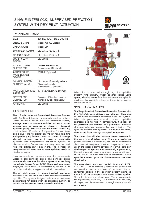
SINGLE INTERLOCK, SUPERVISED PREACTION SYSTEM WITH DRY PILOT ACTUATIONSIZE50, 80, 100, 150 & 200 NB DELUGE VAL VE Model H3, UL Listed CHECK VAL VE Model-CHSPRINKLER ALARM UL Listed (Optional)RELEASE PANEL UL Listed (Optional)WATER FLOW UL ListedSWITCHAUTOMATIC AIR Oil-less RisermountSUPERVISOR Compressor (Optional)AIR PRESSURE PMD-1 (Optional) MAINTENANCEDEVICEMANUAL SYSTEM UL Listed, Butterfly Valve - SHUTOFF VAL VE Standard supply.(Gate Valve - Optional)MAXIMUM WORKING 17.5 Kg./sq.cm. (250 PSI)PRESSURE SYSTEM END Grooved (Standard supply) CONNECTION Flanged (Optional supply)APPROVALUL ListedTECHNICAL DATADESCRIPTIONThe Single Interlock Supervised Preaction System with Dry Pilot Actuation is generally used to protect water sensitive areas such as computer rooms, storage areas of valuable articles, to avoid water damage due to damaged sprinklers or damaged sprinkler piping. Preaction System is also effectively used to have Pre-alarm of a possible fire condition and allows time to extinguish fire by hand held fire extinguishing equipment, prior to water discharge through sprinkler heads. It uses an automatic sprinkler with supplemental detection system. In the event when fire cannot be extinguished by hand held fire extinguishing equipment, the increase in temperature will open one or more sprinkler heads to discharge water .In normal condition, preaction system does not contain water in the sprinkler piping. The sprinkler piping contains air pressure for the purpose of supervising its leak tightness. As per NFPA, the preaction system employing more than 20 automatic sprinklers is to have the sprinkler piping automatically supervised.The dry pilot system in single interlock preaction system will respond to a fire faster than the automatic sprinkler . The system designer selects the detection components for single interlock preaction system to detect the fire faster than automatic sprinkler .When fire is detected through dry pilot sprinkler system, the primary water control deluge valve opens, allowing water flow into the sprinkler piping in readiness for possible subsequent opening of one or more sprinklers.SYSTEM OPERATIONThe Single Interlock Supervised Preaction System with Dry Pilot Actuation utilizes automatic sprinklers and an additional pneumatic detection sprinkler system. When the pneumatic detection system sprinkler operates due to rise in temperature, the loss of air pressure will operate the pneumatic actuator of deluge valve and activate fire alarm devices. The sprinkler system also operates due to fire condition, then water flows through the sprinkler system. The water flow will also produce water pressure in the alarm trim of deluge valve. This may actuate the pressure switch if additionally provided to control the shut down of equipment such as computers or start up of the second alarm devices. In normal condition the integrity of system is automatically supervised by the automatic air supervisory means. Air or nitrogen at 18 PSI (1.26 Bar) pressure is maintained in the sprinkler system up to the downstream of the riser check valve.The supervisory low alarm switch is set at 6 PSI (0.42 Bar). The decreasing pressure will give trouble annunciation due to the loss of pressure, due to abnormal leakage in the sprinkler system piping as a result of the damaged sprinkler or broken pipeline. This will not open the deluge valve. The air pressure is for supervisory alarm only. The automatic supervisory air supply can be maintained through factory set air compressor .Air or nitrogen at 42 PSI (2.94 Bar) is maintained in the dry pilot detection lines and a low pressure alarm switch provided in detection network is factory set at 20 PSI (1.40 Bar).The compressor is compact and can be riser mounted or floor mounted. The supervisory air can be maintained with the tank mounted compressor and air maintenance device.If continuous plant air supply or regulated Nitrogen source is available, then air maintenance device shall be used to maintain the supervisory air supply.The major benefits of this system as compared to the conventional wet/dry sprinkler system are,a) A fire alarm sounds prior to operation of asprinkler, which may enable to extinguishing of thefire by hand held means, before operation of anysprinkler head. This can eliminate water damage. b) Whenever integrity of the piping or sprinkler isdisturbed, n o w ater f lows, o nly t rouble a nnunciationalarm signals. This will avoid water damageto valuable property.c) Early fire alarm is provided by electric detectionsystem, without the delay of water delivery time. INSTALLATION & COMMISSIONINGThe preaction system valves, panel, indicators must be installed in a readily visible and accessible location. The system valves and accessory shall not be installed in an area having temperature less than 4o C (40o F). Heat tracing to system valve and accessory is not permissible. The system must be installed and operated carefully by a trained person, having good knowledge of equipment. All system piping must be flushed thoroughly before commissioning. After initial successful tests, an authorized person must be trained to perform inspection, testing and maintenance of the system. RECOMMENDED SEQUENCE OF INSTALLATIONSIn planning the installation, consideration must also be given to the disposal of relatively large quantities of water that may be associated with draining of the system or performing flow test.1. Install the Deluge Valve on Riser.2. Install the Riser Check Valve above Deluge Valveas shown in installation drawing.3. On completion of system piping, install all the trimsas per trim drawing. Care must be taken to ensurethat Check Valves, Strainers, Valves etc. areinstalled with the flow arrows in proper direction.4. Connect all drain piping as shown in the drawing.5. All unused opening on valve or trim parts mustbe plugged.6. Connect air supply lines.7. Connect all electrical to control panel as perwiring drawing.8. Make sure that all the nut bolts, fittings arescrewed properly.9. Follow the valve resetting and test procedure. RESETTING PROCEDUREa. Close the upstream side stop valve of the Deluge Valve.b. Open drain valves and allow water to drain(if water flow was establish) & close drain valve when water flow has ceased.c. Check all release devices are closed. Inspect therelease devices if system was subject to fire condition.d. Open the air supply line to dry pilot actuator andcheck the pressure is maintained at 42 psi.e. Open the priming line so that the diaphragmchamber reads the system water pressure. Open the manual release station partly to vent the air & then close it.f. Open the upstream side of stop valve to readthe Deluge Valve Inlet water supply pressure.The Deluge Valve is set.g. Open the supervisory air supply line and check thepressure is maintained up to 18 PSI (1.26 Bar) and Control Panel is kept on.i. Check all the trim parts for possible leak. INSPECTION AND MAINTENANCE Inspection and testing is to be carried out only by an authorized and trained personnel. DO NOT TURN OFF the water supply or close any valve to make repair(s) or test the valve, without placing a roving fire patrol in the area covered by the system. Also inform the local security personal and central alarm station, so that there is no false alarm signal. It is recommended to carry out physical inspection of the system at least twice a week. The inspection should verify that no damage has taken place to any components and check for following normal condition of the system.NORMAL CONDITIONa. All main valves are open and sealed with tamperproof seal.b. All drain valves are in closed condition.c. No leak or drip is detected from drip valve.d. All water gauge of deluge valve, should showthe required pressure.e. No leak in any trim or other piping.f. Release panel is on and no abnormal indicationare seen.g. All testing procedure to be verified at Jalgaon.Procedure outlined below will result in operation ofassociated alarm. Concerned authorities to be in-formed about the tests before conducting the tests.QUATERLY TESTWATER FLOW ALARM TESTOpen the sprinkler alarm gong test valve, the waterwill flow through sprinkler alarm and/or water flowswitch. On satisafctory observation close the alarmtest valve.AIR SUPPERVISORY LOW PRESSUREALARM TESTRelease air pressure gradually through valve providedon check valve. When air pressure drops to 6 PSI(0.42 Bar), the supervisory low pressure alarm mustbe observed. Close the valve & observe that airpressure has been established to 18 PSI (1.26 Bar),the supervisory air pressure alarm must come tonormal condition. If required reset the release panel.ANNUAL OPERATION TESTT esting valve operation without causing water upply tothe deluge valve.a. Close the main system valve controlling watersupply to the deluge valve.b. Open the main drain valve provided on deluge inletside and allow water to drain. When water flowfrom drain valve has stopped crack open the mainsystem valve and close the main drain valve partlyallowing the water pressure at inlet ofdeluge valve to raise up to 1.4 Kg. / Sq. Cm.(20PSI) and no more pressure is rising.c. Operate emergency release station; Deluge valvemust open and water flow must be noticedthrough drip valve and the fire alarm bell shouldsound. Close the main supply control valveimmediately and allow water to drain from drainvalve.d. When water flow has stopped, reset the delugevalve as per resetting procedure.The steps b & c must be performed very quickly toprevent water flow to riser.NOTE: For abnormal condition of deluge valve referthe data sheet No. HD235.CAUTIONThe system must be inspected, tested and maintainedas instructed above, in addition to the requirementof NFPA or as per requirement of authority havingjurisdiction. The owner is responsible for theinspection, testing and maintenance of the systemand devices.SINGLE INTERLOCK, SUPERVISED PREACTION SYSTEM WITH DRY PILOT ACTUATIONPART LISTPREACTION TRIM SIZE QUANTITY PER PREACTION TRIM ITEM NO CODE NO DESCRIPTION SIZE/ MAKE200 NB150 NB100 NB80 NB50 NB1BFV WAFER TYPE GEAR OPRT.WITH TAMPER SWITCH *2”, HD MAKE(MODEL NO.HDMW300)1111126458DELUGE VAL VE FLANGE END 2”, HD MAKE (MODEL NO.DV-H3)----1 26455DELUGE VAL VE FLANGE END3”, HD MAKE (MODEL NO.DV-H3)---1-26454DELUGE VAL VE FLANGE END4”, HD MAKE (MODEL NO.DV-H3)--1--26453DELUGE VAL VE FLANGE END6”, HD MAKE (MODEL NO.DV-H3)-1---26457DELUGE VAL VE FLANGE END8”, HD MAKE (MODEL NO.DV-H3)1----31563DRY PILOT ACTUATOR 1/2” HD MAKE (MODEL NO. H1)11111 41951EMERGENCY RELEASE STATION1/2”, HD MAKE (MODEL ERS-1)11111 59392ANGLE VAL VE1-1/4”---22 59394ANGLE VAL VE2”222--69423PRIMING VAL VE1/2”11111 7RESTRICTED CHECK VAL VE1/2”11111 81825ANTI RESET VAL VE (ARV-1)1/2”11111 93569CHECK VAL VE - FLANGE TO GROOVE2”, HD MAKE (MODEL NO. CH)----1 9114345CHECK VAL VE - FLANGE TO GROOVE3”, HD MAKE (MODEL NO. CH)---1-9114346CHECK VAL VE - FLANGE TO GROOVE4”, HD MAKE (MODEL NO. CH)--1--9114343CHECK VAL VE - FLANGE TO GROOVE6”, HD MAKE (MODEL NO. CH)-1---9114347CHECK VAL VE - FLANGE TO GROOVE8”, HD MAKE (MODEL NO. CH)1----101674PRESSURE MAINTENANCE DEVICE*1/2” (PMD-1)22222 11114071PRESSURE GAUGE0-300 PSI, UL LISTED33333 121416SPRINKLER ALARM (GONG BELL)*HD MAKE (TYPE-A)11111 13PRESSURE SWITCH POTTER MAKE, UL LISTED33333 14TRIM FITTINGS11111 15AUTOMATIC SPRINKLER **-----16DRY PILOT LINE SPRINKLER-----17SPLASH PROOF FUNNEL11111* OPTIONAL SUPPLL Y** NOT SUPPLLIED BY HD FIRENOTES:DELUGE VAL VE END CONNECTION (OPTIONAL - G X G/ F X F) F = FLANGE ENDCHECK VAL VE END CONNECTION (OPTIONAL - G X G/ F X G / F X F)G = GROOVE ENDBUTTERFL Y VAL VE END CONNECTION (OPTIONAL - G X G/ WAFER TYPE / LUG TYPE)PRESSURE GAUGE (OPTIONAL - HDP-1 / HDP-2)OPTIONAL TRIM SUPPL Y - LOOSE / SEMI ASSEMBLED)SHAPE OF FITTINGS / VAL VES MAY CHANGE.SYSTEM PIPING, SPRINKLER, DETECTOR NOT SUPPLIED BY HD FIREPRIMING LINE BY OTHERSLIMITED WARRANTYHD FIRE PROTECT PVT. L TD. hereby referred to as HD FIRE warrants to the original purchaser of the fire protection products manufactured by HD FIRE and to any other person to whom such equipment is transferred, that such products will be free from defect in material and workmanship under normal use and care, for two (2) years from the date of shipment by HD FIRE. Products or Components supplied or used by HD FIRE, but manufactured by others, are warranted only to the extent of the manufacturer’s warranty. No warranty is given for product or components which have been subject to misuse, improper installation, corrosion, unauthorized repair , alteration or un-maintained. HD FIRE shall not be responsible for system design errors or improper installation or inaccurate or incomplete information supplied by buyer or buyer’s representatives.HD FIRE will repair or replace defective material free of charge, which is returned to our factory, transportation charge prepaid, provided after our inspection the material is found to have been defective at the time of initial shipment from our works. HD FIRE shall not be liable for any incidental or consequential loss, damage or expense arising directly or indirectly from the use of the product including damages for injury to person, damages to property and penalties resulting from any products and components manufactured by HD FIRE. HD FIRE shall not be liable for any damages or labour charges or expense in making repair or adjustment to the product. HD FIRE shall not be liable for any damages or charges sustained in the adaptation or use of its engineering data & services. In no event shall HD Fire’s product liability exceed an amount equal to the sale price.The foregoing warranty is exclusive and in lieu of all other warranties and representation whether expressed, implied, oral or written, including but not limited to, any implied warranties or merchantability or fitness for a particular purpose. All such other warranties and representations are hereby cancelled.NOTICE :The equipment presented in this bulletin is to be installed in accordance with the latest publication standards of NFPA or other similar organisations and also with the provision of government codes or ordinances wherever applicable.The information provided by us is to the best of our knowledge and belief, and consist of general guidelines only. Site handling and installation control is not in our scope. Hence we give no guarantee for result and take no liability for damages, loss or penalties whatsoever , resulting from our suggestion, information, recommendation or damages due to our product.Product development is a continuous programme of HD FIRE PROTECT PVT. L TD. and hence the right to modify any specification without prior notice is reserved with the company.D-6/2, ROAD NO. 34, WAGLE INDUSTRIAL ESTATE, THANE 400 604, INDIA.• TEL: + (91) 22 2158 2600 • FAX: +(91) 22 2158 2602•EMAIL:***************• WEB: HD FIRE PROTECT PVT . LTD.Protecting What Matters Most to YouXXXXSize 150265380410051506200Actuation Device SDSingle Interlock Supervised Pre-action with Dry Pilot ActuationAir MaintenanceDevice N None 1PMD-12Nitrogen Air Maintenance DeviceControl Panel N None AIncludedCompressor *N None 11/6 HP 21/3 HP 31/2 HP 43/4 HP 5 1 HP 61-1/2 HPXXXCompressor Pressure H42 PSI*Compressor standard supply is 50 Hz., 60 Hz is optional supply.。
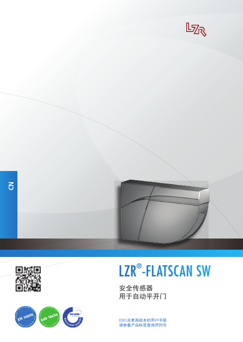
安全传感器 用于自动平开门 0201及更高版本的用户手册说明书
EN16005D I必要时,用质地柔软、禁止使用干布、脏布或其他破坏性的工具擦拭只有受过培训的合格如果被非授权人员进行安装并测试良好后方可门控单元和外壳必须禁止遮盖激光屏。
避免在检测区域内移动物体或光源。
避免在检测区域内排避免产生冷凝水。
禁止暴露在骤变或极端保证传感器在温度低于-10°C时能够持续供电。
禁止直接进行高压清洗。
在发起自学习及调试传感器前,需拆下激光屏如果安装现场在进行建筑施工,则禁止拆下激光屏215473983 610LED-信号结构描述1.外壳2.按钮3.DIP开关4.主-从连接器5.主连接器6.角度调节螺钉7.堵头8.软管固定夹9.软管固定帽10.软管11.锁紧螺钉12.激光头13.激光屏14.激光屏保护壳15.辅助定位装置16.安装底座17.主从式连接线缆18.电源电缆继电器2继电器1LED 闪烁LED 闪烁慢速LED 熄灭LED 闪烁x 次LED 闪烁红-绿LED 闪烁快速过程计算中退出检测区域并等待2 34 45用螺丝刀紧固3颗螺钉。
8Ø 10 mm91011121314«click»确保紧固螺钉的牢固,避免在门运动时产生振动。
234将电缆的导线盘成线环,并按指示放入凹槽内,然后5XR1R1R2R2R2R2R2R2< 1秒1. 2. 4.3.橙色绿色继电器2:门关闭侧的重开脉冲。
主模块> 3秒BA5«click»«click»!PZ19测试和调试在检测区域内放置物体,以检查和确认安全区域的准确位置。
在改变角度、传感器位置或环境后,通常需要发起一次自学习,并测试检测区域的准确位置。
再次打开传感器时,用螺丝刀插入卡槽内,必要时,通过角度调节螺钉调整激光光幕的倾斜角度(2°- 10°)。
在线观看FLATSCAN SW:bea-fl/tutorial服务模式可将安全检测功能解除15分钟,这对于安装过程、自学习过程以及维护过程都十分有用。
SR系列传感器显示表说明书

SR□-R20SR□-C20SR□-R28SR□-C28KKSRC01-A/2-第1页⊙热电偶/热电阻/模拟信号通用输入⊙多种显示单位选择⊙具有显示、报警、电流变送功能⊙带485通讯功能⊙开关电源100-240V AC/DC2222型 号报警点数型号说明KKSRC01-A/2-第3页KKSRC01-A/2-第4页无有无有4~20mA变送电流RS485通讯无无有有报警功能:2:表示两路报警输出外形尺寸(mm):4:48W×48H 6:48W×96H 7:72W×72H 8:96W×48H 9:96W×96H SR系列传感器显示表输出功能:R:无电流输出 C: DC 4~20mA电流输出输入及通讯:0:表示一路输入无通讯功能 8:表示一路输入带RS485通讯(需订货时注明)整机电流 <30mA(220VAC/50Hz)工作电压 100~240V AC/DC 1.整机参数主要技术参数变送输出 4~20mA变送电流,负载电阻600Ωmax 工作环境 0~50℃ 45~80RH%存贮环境 -10~60℃ 25~85RH%耐压强度 电源端、继电器触点、信号输入端 相互之间耐压大于2000VAC 50Hz 1分钟面板防护等级 IP65报警输出 继电器输出负载能力:1A/230VAC 辅助电压输出 DC 24V/30mA通讯功能 RS485通讯接口,MODBUSRTU协议3.单位符号对照表面板名称面板按键操作注:接线如有变动,请以出厂仪表接线图为准(1)、SET键:在测量状态下,短按SET键可进入初级设置菜单,长按SET键可以进入高级设置菜单(再次长按SET键可返回测量状态),每个参数 修改完成后要按SET键确认。
(2)、 (SHIFT)键:在测量状态下,短按 键后,PV窗显示Unit:此时可以按动 来选择显示单位:M、cm、mm、kg、g、mg、Mpa、 pa、ba、Mba、n、W、KW、RPM、Hz、KHz、mV、V、KV、mA、A、KA、Ω、KΩ、℃、F。
北京利达华信模块说明书

北京利达华信模块说明书-CAL-FENGHAI.-(YICAI)-Company One1北京利达华信模块说明书设备的技术支持:主要针对于模块、探头的编码。
EN系列主机采用混合编址。
但为了便于现场编写逻辑关系及后期维护保养建议采取以下顺序编址:感烟探测器→感温探测器→燃气探测器→手动报警按钮→消火栓按钮→输入模块→输入输出模块。
其次是探测器、模块等的接线方式。
一般情况下施工方要了解接线方式,就要考虑到现场有没有预埋走线,是否需要重新布线。
一.现场经常用到的几种探头的技术支持1.LD10EN底座:用于LD3000EN/A、LD3300EN等探测器,采用二总线并联接线方式,TC+,TC-端子不分正负极。
2.LD2000E-A手动火灾报警按钮内部接线图(如图所示):3、4脚是二总线端子,TC2、TC1无极性,1、2脚是一组无源常开接点,通过电压小于30V通过电流100MA,5脚6脚是备用消防电话接口,配合电话手柄使用。
如使用总线电话需要配合总线电话模块使用。
图3.LD2001EN消火栓按钮内部接线图(如图所示):3、4脚是二总线端子,TC2、TC1无极性,1、2脚是一组无源常开接点,接直接启泵线(图),通过电压小于30V通过电流100MA,7脚是24V+,8脚是消防泵的反馈线。
图图4. LD3101/B点型可燃气体探测器内部接线示意图(如图所示):TC+,TC-,24V+,24V-四个端子。
3101/B点型可燃气体探测器探头编码方式是将TC+与24V+短接,TC-与24V-短接,用编码器的红色夹子夹在TC+上,黑色夹子夹在TC-上进行编码。
图2输入模块端子图与接线图示例(如图、所示):6脚5脚是二总线TC+,TC-原则上不分正负极,11脚12脚是一组无源长开点,8脚7脚是一组无源长开点。
端子现场设备上需要加15K线路检测电阻。
图图6.LD6800EC-1输入/输出模块内部接线图(如图所示):1脚24V+,2脚24V-必须分极性,5、6脚TC+、TC-,11、12脚现场反馈信号接入点,需要接82K线路检测电阻。
JB-TB-AEC2201可燃气体报警控制器使用说明书
1. 探测器的安装位置不适当,不能及时,准确监测可燃气体浓度的变化;
2. 选用探测器检测气体类型或灵敏度不合理;探测器的数量不能满足用气场所的要
求;
3. 在没有电源的情况下,报警系统不能工作.当AC电源断开时,控制器自动切换
至备用电池,但电池的工作时间有限,如果没有及时恢复AC电源,控制器将自
探头应安装在一个无大的震动且温度也尽可能稳定的位置上.
气体检测探头安装方式可采用房顶吊装,墙壁安装或抱管安装,应确保安装牢固
可靠,同时应考虑便于维护,标定.
气体检测探头安装高度:
检测天然气,城市煤气等比重小于空气的可燃气体时,采用高出释放源0.5-2m,
且与释放源的水平距离小于5Байду номын сангаас安装;
技和管理人员占80%.
公司采用先进技术,生产工艺,质量管理体系和现代化生产加工设备,
开发生产的智能型可燃气体探测器,报警控制器,质量高,功能强,安装,
调试,使用方便.
公司产品已通过国家消防电子产品质量监督检验中心检验,产品质量
全面达到国家相关标准和要求.
公司按照GB/T19001-2000 idt ISO9001:2000《质量管理体系 要求》
适用于石油化工企业管理系统,油库,泵房,油罐群,气站,宾馆,锅炉房,制药厂,
调压站,高档公寓,智能化小区等工业,民用场所.报警控制器集中管理分布于各检测
点的探测器,处理探测器的故障,报警信号,控制器可以远程手动或根据报警状况自动
开启排风机或关闭管道电磁阀.能有效防止中毒,爆炸,火灾等恶性事故的发生,但并
检测液化石油气等比重大于空气的可燃和/或有毒气体时,采用距地面0.3~0.6
布谷森集成火警系统远程维护手册说明书

Integrated Fire Alarm Systems from BoschRemote Services Handbook21 ABOUT REMOTE SERVICESConnecting to the future 3 The Remote Portal 4The Remote Services Package52 B ENEFITS FOR YOUR DAILY WORKSupporting technicians in the field 6Troubleshooting and support with FSP-5000-RPS7Flexible user management 8 - 9 Operation and real-time awareness Up-to-date system status 10 Service and connection history 10 Maintenance and ServiceEffective service preparation 11 Efficient on-site visits 12Automatic documentation with Remote Maintenance133 MANAGING LICENSES 14 - 15ContentConnecting to the Future1 About Remote ServicesRemote ConnectUse your PC andFSP-5000-RPS toconnect andmaintain a systemRemoteMaintenanceOptimize supportduring and after yourwalk tests on your PC,tablet and phoneWhen you’re managing different security and safetysystems across many locations, technology can beyour greatest asset. Bosch helps to provide your cus-tomers with immaculate remote support and enhancedperformance while optimizing your day-to-day opera-tions. Bosch Remote Services for fire alarm systemscombines all these benefits in one cutting-edge andsecure solution which scales with your business.All Services are managed through the Bosch RemotePortal. It can be used with any browser interface onceyou are registered and a system is connected to it.The connection is encrypted and secured by the SecureNetwork Gateway and Bosch Security Servers.How to manage your fire alarm systems and how thisdirectly benefits the daily comissioning, operationsas well as maintenance work for fire alarm systems isexplained in the following chapters.31 | About Remote Services Remote PortalHow to registerThe Remote Portal can be accessed on the following Link: When first accessing the portal please register an account for your company, which will then function as an administrator account. Every new fire alarm system will connect to this account and its Remote ID. Each particular company account has a unique Remote ID assigned. This Remote ID is required when connecting a fire alarm system to the Remote Portal. System HierarchyAfter a successful login, the system overview on the starting menu, shows all connected fire alarm systems. The names of the systems result from the name as set-up in the configuration of the fire alarm system. All systems can be arranged in freely definable groups that contain multiple systems. This helps you to keep an overview on regions, customers or support groups. Additional groups can be added by clicking on the plus button in the right-bottom corner of the system over-view (see figure above).There is no limit to the depth of the nesting or combi-nation of elements at any level. The Remote Portal dis-plays the hierarchy as a tree structure (granting access to the whole hierarchy, shown on the left-hand side of the screen) and by displaying the system and group cards of the current level on the right hand side of the screen. Use the tree to navigate to any group or level of the hierarchy and cards to drill down in the hierarchy from current level.45Remote Services PackageRemote Services help to efficiently monitor, maintain and service the individual fire detection equipment, ensuring highest safety standards. In the following section you find a brief overview of the three innovative features provided in the package.1 | About Remote ServicesCity sitesOpera House, MunichRemote ConnectRemote AlertA remote internet connection that enhances your operations. Secure remote connection for:• Configuration • Service• TroubleshootingEasy setup within 30 minutes.Optimized for seamless integra-tion into RPS.Customized alerts, sent to you and your customers for additional peace of mind.Faults and alarms are automat-ically transmitted to mobile devices via SMS and E-Mail.Easy user management: define responsibilities for specific people as needed.RemoteMaintenanceMaintain your system efficiently with the integrated tool that monitors the condition of every installed device.Access live fire system data.Prepare detailed maintenance documentation while testing with a tablet-optimized interface. Stay connected with the panel while maintaining the system.Receive easy-to-understand fire system data.Service history is stored within the Remote Services Portal.Efficiency increase of at least 25%:Via simultaneous maintenance and detailed reporting.Intended end customer gets infor-mation, enabling more effective maintenance of your system.6Remote Connect from Bosch delivers unparalleled connectivity with little to no IT expertise required. Enjoy the advantages of an entirely remote configura-tion, not just a remote display. Avail yourself of the 24/7 access and availability, thus even global monitoring is no challenge anymore. Enabling a prompt reaction time significantly augments your customer satisfaction. Your assets will always be safe and protected, thanks to Remote Connect.Supporting Technicians in the Field2 Benefits for your daily workFurther benefits include the possibilities of preventive maintenance and the monitoring of detectors. As a result maintenance and travelling costs will be reduced due to shorter system downtime.7When you have successfully connected a system to the Remote Portal, you can use Remote Connect .Remote Connect allows you to connect to a fire alarm system using the Secure Network Gateway from Bosch with very few steps necessary. The configuration software FSP-5000-RPS connects to the systems as if you were on-site. If allowed by local regulations, you then may modify configuration, remotely control the system via the Remote Terminal as well as update or troubleshoot anytime and from anywhere you need to.Especially demanding applications require a lot of atten-tion during the initial set-up and commissioning phase – But oftentimes configuration experts are needed to fine-tune the system: With Remote Connect experts can now support technicians in the field remotely from their office, once an issue occurs.Troubleshooting and Support with FSP-5000-RPS2 | Benefits for your daily work - Supporting technicians in the fieldWell trained configuration experts can quickly modify necessary details and guide the local technicians as if they were themselves on-site. This way your company optimizes both costs due to a much more efficient allo-cation of staff, but also the top-line of business by pro-viding better commissioning and faster reaction times. Ultimately this creates more business opportunities for you, allowing your teams expertise to scale to its full potential.8The Remote Portal allows you to manage your systems according the way you run your business. With a highly adaptive user management you can differentiate three user levels: administrator, technician and customer. Each of them have their distinctive set of privileges on the Remote Portal and via FSP-5000-RPS.2 | Benefits for your daily work - Supporting technicians in the fieldFlexible User ManagementAdministratorTechnican AAs an Admin you can create andmanage different projects.Factory DresdenCompany CologneOpera MunichCustomer AUse RemoteMaintenance for Walktests and Sensor ReportsCan receive alerts about TroublesCan receive alerts via e-Mail or SMS when fire isdetectedTechnician A Technician A,Customer ATechnician C Customer CTechnician B Technician B, ACustomer BBy default any system within the Remote Portal is not accessible by technicians or mobile users until access is granted explicitly. Administrators always have access to all systems connected to their Remote ID. The details of these access rights are explained hereafter.92 | Benefits for your daily work - supporting technicians in the fieldAdding a technician to a group grants access to all systems of this group and the systems of any nested group. Access rights accumulate from top to bottom of the hierarchy, as explained in the following example which is illustrated in the box on the right side.Technician access can be granted either for a particular system or for a set of systems by adding a technician to a system or group respectively. Technicians access allows to view the particular systems in the Remote Portal via a browser and additionally enables access to the system via the client software such as FSP-500-RPS. For further details on granting access and permis-sion, please refer to the user section of this document.Removing AccessRemoving access is only feasible on the highest entrylevel. Based on the example, the access for Technician A can only be removed on the highest entry level of Group 1, 1-1. If access is removed at a lower level such as 2-1, removal is denied. Removal of access, when applicable, is shown via a red …-“ sign in the bottom right corner of the menu.Status AggregationCoordinating and establishing systems in a group hier-archy, results in the aggregation of status information of all the systems within a group. Each group always displays the aggregate status of all systems (in par-ticular systems functionality, connectivity and service status), with failure status appearing in the top group, displayed by the status icons. This provides a quick way to verify functionality of a large number of devices contained in a group. Further, this enables simplified navigation in case of occurring errors.Granting AccessGroup 1 - Technician A, B System 1-1 System 1-2Group 2 - Technician C System 2-1 System 2-2 - Technician DFor this example technicians A and B can access systems 1-1, 1-2, 2-1 and 2-2, whereas technician C can only access system 2-1 and 2-2 and technician D only system 2-2. Resulting access rights are shown at every level, as an example, in system 2-2 all technicians are granted access, matching the configuration shown in the example above.10Once a system is commissioned and running at the customer‘s site, you want to make sure that you are up-to-date on its performance. Remote Alert is the feature of Bosch Remote Services that guaran-tees to keep you in the loop should anything happen.In case of any event, service or alarm all subcribers will be notified, in other words, all defined recipi-ents, are immeadiately notified via E-mail or SM S. Should multiple triggering events of one specific type occur, only the initial ten events within a 24h period will be sent, reducing the number of messages in case of larger event bursts.Furthermore the Remote Portal limits total amount of SMS to 50 per day, per account. The portal alert his-tory however always shows all events, independent of whether a message was sent or not.You can decide who will be informed in case of an alarm or system troubles. Depending on your settings they will get an SMS or E-Mail notification.The following overview shows the different types of event and notification channels. SM S notifications include only a short information text of the type of event, the site and and its location, while the E-mail feature offers additional more detailed reports.Up-To-Date System StatusService and Connection HistoryWhen you select a system in the system overview on the Remote Portal, you can also get insights into the alarm and service history.Via the walktest feature within the service history you can get an overview when the last service visit was conducted. It also allows to monitor how many points were checked at a certain time as well as to check specific reports of the system and the detector.3 Operation and Real-Time Awareness113 | Operation and real-time awarenessShows if the detector is in revision mode.Effective Service PreparationIn the service industry every minute counts. Therefore, Remote Maintenance offers you live system data down to an LSN element of the complete fire alarm system. You can find this data here for each LSN loop:Using a periodical polling of the elements connected to the fire alarm system, you can get an overview on the sensor data of detectors on the LSN bus. This allows you to preemptively know the pollution state of each individual detector. There is no more uncertainty what to expect before you reach the customer site.You only need to take the specific new detectors to the customer in need for replacement. On site you can immediately start the work on critical elements, ensur-ing your customer’s business continuity. The data help-ing you to prepare the specific service visit, is illus-trated below according to the automatic fire detector range from Bosch.123 | Operation and real-time awarenessEfficient on-site VisitsWhen you are on-site to do maintenance not only every minute counts, but also you want to minimize the inter-ruption to your customer’s business. The integrated walk test feature of Remote Maintenance helps you to be faster when testing detectors. With the click of a button you start the walk test on any device with a web browser and all detectors in revision mode appear ready for the automated testing. When you introduce test gas for triggering, an optical detector will automat-ically show itself as “tested” – This way you do not need to monitor the panel display for successful triggering and the Remote Portal will handle the documentation for you.If there is a fire alarm on another loop of the system, the Remote Portal will show a pop-up warning message – depending on local regulations this feature helps you to reduce the necessary manpower for the walk testfrom two to just one technician on site.133 | Operation and real-time awarenessRepeat until alldetectors were tested…Start walktest“Use your mobile device to make use of the Remote Portal during the walktest. Select the System and Panel where you are going to test and click: …Start walktest“.Test the detectors as usualTest the detectors in the building with your usualequipment.3Get feedback from the Remote Portal everytime a detector wastested successfullyThe Remote Portal offers visual and acoustic feedback to prove immedeately if a detector was successfully tested.4Download the ReportAfter every walktest you can download a detailed Report from the Remote Portal.5Stop the walktest after testing all detectorsIf you want to continue the walktest the next day, just close the Remote Portal. To end the whole walktest, klick …Stop Walktest“.6Put the detectors you want to test in revision mode on the panel1Automatic Documentation with Remote Maintenance14Note: The Remote Portal intelligently parses licenses information from the information entered in the dialog, it is not necessary to apply special formatting or remove extra text. Multiple license codes can be added at once. Licenses added are saved in the Remote Portal for use, but only consumed when the corresponding is activated(manually or via auto-renewal). This allows having a stock of licenses in the Remote Portal for immediate use, without inactive licenses expiring inadvertently.Dear customer,please follow the steps below to add your recently purchased licenses to your account:1. Log into your account at https://2. Click the …Licenses“ tab in the top bar.3. Click the …Add Licenses“ button.4. Copy and paste the entire license information between the dashed lines to the browser dialog box and click …Add“.----- license information (begin) -----Fire panel remote services bundle:1234: 1111-2222-3333-44441235: 2222-3333-4444-55551236: 3333-4444-5555-6666----- license information (end) -----Thank you for using Remote Services.Regards,Bosch Security Systems154 | LicensingUsing Licenses and Activating ServicesSubscribing to a service for a system will start a check for available licenses. A suitable license in the Remote Portal account will be used up and subscribed to the fire alarm system for which the service is activated. Licenses are assigned from available stock - A particu-lar license‘s assignment can be checked from the infor-mation shown on the license in the Remote Portal. The remaining life-time of a license assigned to a ser-vice is shown in the service section of a device. Once the license expires the service is no longer available and requires an extension. License expiration is high-lighted in red in a device‘s service section and the sys-tems overview screen at the services icon.Auto-RenewalFor convenience and to avoid service interruptions, services can be configured for auto-renewal upon expiry. This can be done at time of service subscription or the service settings screen for a particular service: Auto-renewal requires a license to be available when renewal is due, otherwise renewal fails. Use the license management to plan and coordinate your particularlicenses in regular intervals.Managing Licenses - Future License UsageThe licenses tab provides the necessary information and actions to manage licenses. At the top of the screen current and predicted license usage is displayed, bro-ken down by service /license type:Based on the number of devices subscribed, the remaining life-time of the subscription and auto- renewal of service subscriptions, the Remote Portal predicts when additional service licenses are needed, marking the estimated demand of licenses in red. Note that this estimation will change when additional devices are subscribed to a service.Individual License Status and MaintenenceIndividual licenses are shown below the license usage section of the screen and provide information on each purchased license, the license status (avail-able, assigned and expired) as well as its validity and assigned system.Licenses that have not yet been assigned to a system (are in available state) can be removed from an account by clicking the trashcan symbol of the license. This allows you to transfer licenses to another account or to make licenses unavailable for use.License deletion is immediate and permanent. You must copy and save the license key presented in the warning dialogue in order to reuse at a later stage.Bosch Sicherheitssysteme GmbH Robert-Bosch-Ring 585630 GrasbrunnGermany。
各种消防报警模块的参数、特点及使用方法
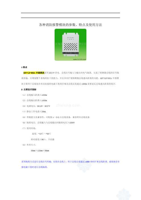
各种消防报警模块的参数、特点及使用方法1特点GST-LD-8321中继模块采用DC24V供电,总线信号输入与输出间电气隔离,完成了探测器总线的信号隔离传输,可增强整个系统的抗干扰能力,并且具有扩展探测器总线通讯距离的功能。
GST-LD-8321中继模块主要用于总线处在有比较强的电磁干扰的区域及总线长度超过1000m需要延长总线通讯距离的场合。
2主要技术指标(1)总线输入距离≤1000m(2)总线输出距离≤1000m(3)电源电压:DC18V~DC27V(4)静态工作电流≤20mA(5)带载能力及兼容性:可配接1~242点总线设备,兼容所有总线设备(6)隔离电压:总线输入与总线输出间隔离电压≥1500V(7)使用环境:温度:-10℃~+50℃相对湿度≤95%,不结露(8)外形尺寸:85mm×128mm×56mm采用隔离方式进行总线信号传输,安装在总线上,用于总线长度超过1000米时扩展总线距离,或现场存在强电磁干扰时进行总线隔离。
1特点GST-LD-8300型输入模块用于接收消防联动设备输入的常开或常闭开关量信号,并将联动信息传回火灾报警控制器(联动型)。
主要用于配接现场各种主动型设备如水流指示器、压力开关、位置开关、信号阀及能够送回开关信号的外部联动设备等。
这些设备动作后,输出的动作信号可由模块通过信号二总线送入火灾报警控制器,产生报警,并可通过火灾报警控制器来联动其它相关设备动作。
输入端具有检线功能,可现场设为常闭检线、常开检线输入,应与无源触点连接。
本模块可采用电子编码器完成编码设置。
当模块本身出现故障时,控制器将产生报警并可将故障模块的相关信息显示出来。
2主要技术指标(1)工作电压:总线24V(2)工作电流≤1mA(3)线制:与控制器的信号二总线连接(4)出厂设置:常开检线方式(5)使用环境:温度:-10℃~+55℃相对湿度≤95%,不结露(6)外壳防护等级:IP30(7)外形尺寸:86mm×86mm×43mm(带底壳)电子编码,可接收设备常开或常闭开关量信号。
防触电控制器介绍

防触电控制器介绍防触电控制器是一种专门用于保护人身安全的电气安全设备。
它的主要作用是监测电气设备中是否存在漏电和接触电流超过安全范围,一旦检测到异常情况,立即切断电源,以防止触电事故的发生。
防触电控制器一般由三个主要部分组成:漏电检测模块1.:漏电检测模块通过监测电路中的电流变化来判断是否存在漏电情况。
当电路中出现漏电时,漏电检测模块会立即发出信号,通知控制器进行相应的处理。
电源控制模块 2.:电源控制模块负责控制电源的供电和切断。
当漏电检测模块发出信号时,电源控制模块会立即切断电源,以保证人员的安全。
报警提示模块 3.:报警提示模块用于向使用者发出警示信号,提醒其存在安全风险。
一般来说,报警提示模块会通过声音或者灯光等方式进行警示,以便使用者及时采取措施。
除了以上三个主要部分,一些高级的防触电控制器还可能包含额外的功能模块,以提高其防护能力和使用便捷性。
例如,一些防触电控制器可能配备了远程监控功能,可以通过网络远程监测设备的运行状态;还有一些防触电控制器可能具备自动复位功能,可以在故障排除后自动恢复供电。
防触电控制器广泛应用于各种需要电源供应的场所,特别是对于一些电气设备密集、人员流动频繁的场所,如住宅楼、商业建筑、工厂、医院等。
它能够有效减少电气意外事故的发生,保障人们的生命安全。
此外,根据不同场所和需求,防触电控制器还有不同的型号和规格可供选择。
总之,防触电控制器是一种重要的电气安全设备,它通过监测漏电和接触电流,及时切断电源,并通过报警提示等方式提醒用户存在安全风险。
它的广泛应用可以有效预防触电事故的发生,保护人员的身体安全。
风险管理和安全设备 - 星金雷烟感detector说明书

The SharpEye Model 20/20SI is a new version of the Triple IR Spectrum Flame Detector designed to provide maxi-mum fire protection. The optical sensors and filters have been carefully selected to en-sure the greatest degree of spectral matching to the radiant en-ergy emissions of fire, and the lowest degree of match-ing to non-fire stimuli.The patented Triple IR (IR3) circuit design scans for oscillating IR radiation (1 to 10 Hz) in the spectral bands ranging from 4.0 to 5.0 microns. This highly advanced detector uses programmable algorithms which check the ratio and correlation of data received by the three sensors.This version of the IR3 has a sealed electronics &sensor section to ensure protection from the environ-ment during installation.The microprocessor design allows for unique field programmability not found in similar detectors, making the 20/20SI highly immune to false alarms.The detector has applications in a wide range of industrial and commercial facilities, where the threatof accidental fire involves hydrocarbon fuels, such as gasoline, kerosene, diesel fuel, aviation jet fuels like JP-4, JP-5, JP-8, hydraulic fluids, paints and solvents,hydrocarbon gases like ethylene and polyethylene,natural gas (LNG), town gas, liquefied petroleum gas (LPG), methane, ethane, propane, etc.The patented Triple IR design offers two to three times the detection distance of anyconventional IR or UV/IR detector.•Aircraft Hangars - landing gear pits, under-wing and over-wing protection•Automotive - manufacturing, paint spray booths •Chemical Industry - production, storage, trans-portation•Explosives & Munitions - handling and storage •Oil & Gas - exploration, production, storage and offloading•Offshore Platforms - fixed rigs and floating vessels FPSO•Onshore - refineries, loading terminals, pipelines •Paint - manufacturing facilities•Petrochemicals - production, storage, shipping facilities•Pharmaceutical Industry•Power Generation Facilities - pump areas,generator rooms, unmanned stations, gas-fired and coal-fired reactors•Printing Industry - solvent handling, presses,drying processes•Tank Farms - floating-roof and fixed-roof tank areas•Warehouses - storage facilities for flammable materials•Waste Disposal Facilities - incineration, pro-cessing and storage of flammable waste materials (solids, liquids, gases)Applications• Triple Spectrum Design • Sensitivity Selection• User Programmable Configuration • Highly Immune to False Alarms• Automatic and Manual Built-In Test (BIT)• Standard 4-wire Connection• 4-20mA sink or source (3-4 wires) configuration • RS-485 Modbus Compatible • MTBF Minimum 100,000 Hours • 3-Year Warranty• FM, ATEX and Gost K ApprovedTel 1800 999 902Fax 1800 999 903GasTech Australia Pty Ltd Wangara Western Australia 606524 Baretta Rd.auDS-F-SI, June 2007Power SupplyOperating Voltage: 18-32 VDC Power consumption Max. 70 mA in stand-by Max. 110 mA in alarm Electrical Connection2 x 3/4" - 14NPT conduits or 2 x M25 x 1.5 mm ISO Electrical Input Protection According to MIL-STD-1275B Electromagnetic CompatibilityEMI/RFI protected CE MarkedDimensions 4.7" x 5.2" x 5.2" (100 x 132 x 132 mm)Weight Aluminum: 8.1Lb (3.7 Kg)St.St 316L: 14.3Lb (6.5 Kg)EnclosureAluminum, heavy-duty copper free (less than 1%), white epoxy enamel finish.Optional - Stainless Steel 316L with electro polish finish.Environmental Standards Meets MIL-STD-810C for Humidity, Salt & Fog, Vibration, Mechanical Shock, High Temp, Low Temp Water and DustIP66 and IP67 per En60529NEMA 250 6PSpecifications subject to changesSpectral Response Three IR Bands Detection RangeGasoline 200 ft (60m)IPA (Isopropyl Alcohol) 90 ft (27m)(Highest Sensitivity Setting n-Heptane 200 ft (60m)Methanol 76 ft (23m)for 1 ft 2 (0.1m 2) pan fire)Diesel Fuel 140 ft (42m)Methane*50 ft (15m)JP5150 ft (45m)LPG (Propane)*60 ft (20m)Kerosene150 ft (45m)Polypropylene Pellets 16 ft (5m)Alcohol (Ethanol)90 ft (27m)Office Paper60 ft (20m)*20" (0.5m) long 8" (0.2m) width plume fireResponse TimeTypical 5 sec.Adjustable Time Delay Up to 30 sec. (up to 20 sec. in compliance with FM requirements)Sensitive Range4 Sensitive Ranges for 1 ft 2 (0.1m 2) gasoline pan fire:from 50 ft (15m) to 200 ft (60m)Field of View 90˚ horizontal, 90˚ vertical Built-in-Test Manual and Automatic BIT Temperature Range Operating: -40°F (-40°C) to 160°F (70°C)Operating Option: -40°F (-40°C) to 185°F (85°C)Storage:-65°F (-55°C) to 185°F (85°C)Humidity Up to 95%ATEX EX II 2G, EExd IIB + H2 T5 (70°C) ,T4 (85°C)EX II 2G, EExde IIB + H2 T5 (70°C)FMClass I Div. 1, Groups B, C & D Class II Div. 1, Groups E, F & GRelays Alarm - 2A at 30 VDC, 0.5A at 250 VAC Fault and Accessory - 5A at 30 VDC and 250 VAC Fault relay normally closed, others normally open 4-20mASink (source option) configuration Fault: 0 ±0.5mA BIT Fault: 2mA ±10%Normal: 5mA ±10%Warning:10mA ±5%Alarm:15mA ±5%Resistance Loop: 100-600 ΩRS-485The detector is equipped with an RS-485 communication link that can be used in installation with computerized controllers. The RS-485 is Modbus compatibleFire Simulator 20/20-310Swivel Mount 20/20-003 (St. St. 316L)PDA Kit799820, 799810。
- 1、下载文档前请自行甄别文档内容的完整性,平台不提供额外的编辑、内容补充、找答案等附加服务。
- 2、"仅部分预览"的文档,不可在线预览部分如存在完整性等问题,可反馈申请退款(可完整预览的文档不适用该条件!)。
- 3、如文档侵犯您的权益,请联系客服反馈,我们会尽快为您处理(人工客服工作时间:9:00-18:30)。
防区报警模块使用说明书
SR-2201A 单防区报警模块使用说明
总线通讯功能的防区扩展设备,其
对于与远距离的探测设备的连接、或
在周界防范等场合中非常实用。
1. 性能特点:
●可接入一个有线探测设备
●总线通讯方式
●探测设备为常闭输入
3.
●接线说明:如果和报警主机共用电源,将“红、绿、黄、黑”4芯线分别与主机的“红、
绿、黄、黑” 4端子相连;如果和报警主机不共用电源,将“绿、黄、黑” 3芯线
分别与主机的“绿、黄、黑” 3端子相连,将“红、黑” 2芯线与自己的电源正、
负极相连。
●在同一台报警主机上使用时,每一个报警模块有自己的唯一地址,不能与其它报警模
块的地址相同。
地址范围及设定,请参考报警主机的安装或使用手册。
2.指示灯说明
●电源状态指示灯说明:输入电源的电压大于最低工作电压时, 电源状态指示灯常亮;
一旦发现输入电源的电压低于正常工作电压时,电源状态指示灯最少快速闪烁5秒,
如果一直没有恢复,电源状态指示灯会一直闪烁。
●通信状态指示灯说明:
1.常亮:模块接收到正常通信;
2.快速闪烁(1秒钟闪烁4次):模块1秒钟内没有接收到任何通信数据;
3.慢速闪烁(1秒钟闪烁1次):模块接收到数据,但5秒钟内没有接收到任何正确
的数据。
注意:在连接SR-2201A之前先断开系统电源,请勿带电操作!。
