3M充消磁器用户手册
西安鸣士机电 KMX-03 1(T)H 型充退磁控制器 说明书
KMX-03/1(T)H型充退磁控制器使用说明书西安鸣士机电开发有限公司一、 概述KMX -03/1(T )H 充退磁控制器是在我公司原KMX 系列产品的基础上,进行了重新设计,其特点如下:1.充、退磁操作可通过三位开关进行;2.根据给定的退磁曲线自动完成退磁过程,能使每块吸盘达到最佳的退磁效果。
二、型号及技术参数型号额定输入电压(V)输出电压(V)最大输出电流(A)退磁时间(S)KMX-03/1(T )HAC127V DC0~110V3A8S注:选择KMX 系列的最大输出电流一定要大于控制吸盘的最大额定电流值。
KMX-03/1TH 无连锁功能三、 使用条件1.环境温度:-10℃~+40℃; 2.相对湿度:≤90%(20℃);3.环境:使用地点应无易燃、易爆、导电尘埃及腐蚀性气体; 4.输入电压波动范围:±10%以内;5.磨削工件时,注意不要使冷却水、铁末、粉尘进入电器箱内,以免引起电器短路。
四、 安装、调试1、 对电磁吸盘的要求:1.1 电气参数与控制器相匹配,吸盘的额定电流= ;吸盘内阻值1101.2 线圈内部无匝间短路及开路现象;1.3 用500V 兆欧表测量,磁盘对地绝缘电阻应不低于1MΩ。
2、 接线方法(参见外接线图,端子号码印于印制板上)2.1 外接线端子图: 注:LED1、LED2为发光二极管,用于外接指示(可选)。
LED1—充磁指示 LED2—退磁指示LED2DC0~110V AC220V 3.3K/2W2.2 3#、4#接交流输入。
2.3 1#、2#为直流输出。
2.4 5#、7#、8# 用于工作状态控制。
工作状态有三种:充磁(5#、8#接通)、停磁、退磁(5#、7#接通)。
停磁时,5#、7#、8#都不接通,因此,需用三位开关。
2.5 5#、9#、10#为外接输出电压调节用的电位器,9#为滑动端,(可根据需要决定是否选用)。
2.6 根据需要决定是否外接状态指示。
2.7 11#,12#为欠电流(欠磁)保护用继电器触点,以便与主机磨头和磁盘旋转联锁,防止因失磁造成伤害。
3M使用手册
3Scotch-Grip TMIndustrial Adhesive4799Features•Quick drying with fast strength buildup.•Provides low soak in on most porous substrates.•Dries to a flexible, water resistant bond.•Can be used to bond most EPDM rubber, sponge rubber, rubber sheeting, felt, canvas,linoleum and other lightweight materials to many metals, woods, concrete and many plastics.Handling/Application Information D irections for Use1.Surface Preparation: Surfaces to be bonded must be clean, dry and dust free. Wiping withsolvent such as Scotch-Grip TM Solvent No. 3 will aid in removing oil and dirt.*2.Application Temperature: For best results the temperature of the adhesive and thesurfaces being bonded must be at least 65°F (18°C).3.Application: Stir or agitate well before using.Porous Surface(s): Brush a uniform, generous coat of adhesive on the least poroussurface to be bonded. Assemble the materials immediately with sufficient pressure toensure contact.Non-Porous Surface(s): Apply a uniform coat of adhesive to each surface. Allowadhesive to dry until it is tacky, but does not transfer. Assemble materials withsufficient pressure to ensure contact.4.Cleanup: Excess adhesive may be removed with solvent such as Scotch-Grip TM SolventNo. 2.**Note:When using solvents, extinguish all sources of ignition in the area and follow the manufacturer’s precautions and directions for use when handling such materials.(Supersedes June, 1995)Typical Physical Properties Note:The following technical information and data should be considered representative or typical only and should not be used for specification purposes.Viscosity (approx.)7,500-18,000 cps.Brookfield Viscometer RVF #6 sp. @ 20 rpmSolids (by wt.)28-35%Base SBRColor BlackNet Weight (approx.) 6.6 - 7.0 lbs./gal.Flash Point (closed cup)-14°F (-26°C)Solvent Petroleum Distillate, n-hexane and toluene Note:Appropriate application equipment can enhance adhesive performance. The user is responsible for evaluating application equipment in light of the user’sparticular purpose and method of application.1.Pumping: Use a 5:1 ratio double acting, ball check pump with a 3 inch diameter air motor.All packings and glands in contact with the adhesive should be Teflon®coated.2.Hoses: Material hoses should be nylon lined with a working pressure of 500 psi or greater.3.Brushes: Brushes designed for use with oil based paint may be used.Application Equipment SuggestionsScotch-GripTMIndustrial Adhesive 4799180°PEEL STRENGTH – Canvas/SteelTimeTest Value@ 75°F (24°C)Temp.(lbs./in. width)1 day 75°F (24°C)15.53 days 75°F (24°C)225 days 75°F (24°C)257 days 75°F (24°C)25.52 wk.75°F (24°C)27.53 wk.75°F (24°C)28after 3 wk.-30°F (-34°C)14after 3 wk.150°F (66°C)8.5after 3 wk.180°F (82°C)5Typical Adhesive Performance CharacteristicsNote:The following technical information and data should be considered representativeor typical only and should not be used for specification purposes.Storage: Store product at 60-80°F (16-27°C) for maximum storage life. Higher temperatures reduce normal storage life. Lower temperatures cause increased viscosity of a temporary nature. Rotate stock on a “first in-first out” basis.Shelf Life: When stored at the recommended conditions and kept in the original, unopened container, this product has a shelf life of 1 year from date of shipment.Storage and Shelf Life3Adhesives Division3M Center, Building 220-7E-05St. Paul, MN 55144-10001-800-364-3577 or 612-737-6501T eflon is a registered trademark of E.I. DuPont de Nemours Co.Printed in U.S.A.©3M 199778-6900-2823-4For Additional Product Safety and Health Information, See Material Safety Data Sheet, or call:Recycled Paper 40% pre-consumer 10% post-consumerT o request additional product information or to arrange for sales assistance, call toll free 1-800-362-3550.Address correspondence to: 3M Adhesives Division, 3M Center, Building 220-7E-05, St. Paul, MN 55144-1000. Our fax number is 612-733-9175. In Canada, phone: 1-800-364-3577. In Puerto Rico,phone: 1-809-750-3000. In Mexico, phone: 5-728-2180.For Additional Information 3M MAKES NO WARRANTIES, EXPRESS OR IMPLIED, INCLUDING, BUT NOT LIMITED TO, ANY IMPLIED WARRANTY OF MERCHANT ABILITY OR FITNESS FOR A P ARTICULAR PURPOSE. User is responsible for determining whether the 3M product is fit for a particular purpose and suitable for user’s method of application. Please remember that many factors can affect the use and performance of a 3M Adhesives Division product in a particular application. The materials to be bonded with the product, the surface preparation of those materials, the product selected for use, the conditions in which the product is used, and the time and environmental conditions in which the product is expected to perform are among the many factors that can affect the use and performance of a 3M product. Given the variety of factors that can affect the use and performance of a 3M product, some of which are uniquely within the user’s knowledge and control, it is essential that the user evaluate the 3M product to determine whether it is fit for a particular purpose and suitable for the user’s method of application.Important NoticeIf the 3M product is proved to be defective, THE EXCLUSIVE REMEDY , A T 3M’S OPTION, SHALL BE TO REFUND THE PURCHASE PRICE OF OR TO REP AIR OR REPLACE THE DEFECTIVE 3M PRODUCT . 3M shall not otherwise be liable for loss or damages, whether direct, indirect, special,incidental, or consequential, regardless of the legal theory asserted, including negligence, warranty, or strict liability.Limitation of Remedies and LiabilityThis Adhesives Division product was manufactured under a 3M quality system registered to ISO 9002standards.Refer to Product Label and Material Safety Data Sheet for Health and Safety Information before using this product.Precautionary Information。
3M Versaflo M-Series 头盔用于压力和供应空气氩气器说明书

3M ™ Versaflo ™M-Series Headgear for Powered and Supplied Air Respirators/VersafloAdvanced protective headgear. Applied to making work more comfortable.Easy maintenanceEasily removable parts allow simple cleaning, maintenance and replacement.Easily adjustable suspensionFeaturing an articulating ratchet suspension, M-Series products can be easily adjusted for the comfort of each individual user. The smooth ratchet mechanism allows for precise tightening control.VersatilityTo suit a wide range of needs, industries andapplications, Versaflo ™M-Series headgear offer faceseals, covers and shrouds in a variety of fabrics. Accessories include earmuffs,peel-offs and a chin strap.23M ™ Versaflo ™M-Series headgear for powered and supplied air respirators are lightweight, compact and easy to maintain while helping to provide the wearer with protection from a range of hazards. Their versatility and comfort help make them popular for many applications.Dependable protection, exceptional comfort and ease of useDirected airflowA built-in air deflector allows users to direct the location of the airflow inside the headgear for increased control and comfort.Modern, well-balanced, comfortable designVersaflo ™M-Series headgear is lightweight, with excellentbalance. The suspension includes six-point textile straps (four-point straps for 3M ™ Versaflo ™ M-206 Faceshield) for excellent comfort and weight distribution.Coated visor with The visor design combines excellent peripheral and downward vision with good optical clarity. Coated visoroption provides added chemical and scratch resistance in certain environments.33M ™ Versaflo ™ M-Series Faceshields, Hard Hats and Helmets* W eight is complete assembly.** C onsult 3M Technical Data Bulletin #175 and the M-Series User Instructions for additional information on the Assigned Protection Factor (APF) of 1,000. In Canada, follow CSA Z94.4 or the requirements of the authority having jurisdiction in your region.M-206M-2073M ™ Versaflo ™ M-Series Complete System Kits1 | Choose your headtop42 | Choose the appropriate breathing tube37309 Sm/Med (Approx. 28")37310 Med/Lg Length Adjusting53M Automotive Aftermarket Division (AAD) product numbers are found in grey type on selected products.* C onsult 3M Technical Data Bulletin #175 and the M-Series User Instructions for additional information on the Assigned Protection Factor (APF) of 1,000. In Canada, follow CSA Z94.4 or the requirements of the authority having jurisdiction in your region. ** Future configuration with TR-600 models.† ANSI Z89.1-2009 Type II Class G. CAN/CSA Z94.1-05 Class G protective helmets.†† For TR-300 Models — operating altitude approx. sea level to 2,600 ft. (800m). For altitudes above 2,600 ft., contact 3M. For TR-600 Models — operating altitude approx. -328 to 16,404 ft, (-100 to 5,000m). For altitudes outside this range, contact 3M.‡ L-705SG, L-901SG and L-905SG assemblies meet the requirements of ANSI Z89.1-2009 Type II, Class G protective helmets. L-901SG and L-905SG assemblies also meet the requirements of CAN/CSA Z94.1-05 for Class G protective helmets. Note the L-140 chin strap must be used for ANSI Z89.1-2009 Type II (protection from side impacts). Consult User Instructions before use.‡‡V-199 adapter included in assembly and also sold separately.3 | Choose your air delivery unit25 ft. W-9435-25/25 ft. W-2929-2525 ft. W-3020-25/6Build your own Versaflo ™ system, or choose from one of our complete system kits.These kits offer the convenience of a complete system tailored to your application — all in one box.A complete Powered Air Purifying Respirator ready-to-use kit provides a simple way to purchase a complete PAPR system for use in rugged environments such as industrial, demolition, grinding, metal finishing and casting operations. Includes: M-307 Respiratory Hard Hat, a TR-600 series PAPR kit with Breathing Tube, High Durability Belt, and more.A complete particulate PAPR system for applications wherecombined respiratory, eye, face and hearing protection is required or desired. Includes an M-206 Respiratory Faceshield, TR-306N PAPR with High Durability Leather Belt, BT-30 Length Adjusting Breathing Tube, HE filter, spark arrestor/prefilter, headgear-mounted earmuffs and battery charger. A complete PAPR solution for painters. Includes a GVP-CB PAPR Assembly (including battery, comfort belt and charger),a GVP-441 OV/HE Filter with GVP-119 shower cover, a BT-20LBreathing Tube with BT-922 Breathing Tube Cover and an M-206 Faceshield.For painters who want to use a Supplied Air Respirator.Includes a V-100 Vortex Cooling Assembly, a BT-20L Breathing Tube with BT-922 Breathing Tube Cover and an M-206 Faceshield. A supplied air hose (sold separately) is required to complete the NIOSH-approved system. Contact 3M Technical Service for information on air source options and air quality requirements.Heavy Industry PAPR KitHeavy Industry PAPR KitBelt-Mounted PAPR KitPainter’s Supplied Air Respirator KitTR-600-HIKTR-300-LIKGVP-PSK2/37335SA-100-PSK/373363M ™ Versaflo ™ M-Series Complete System Kits7 Parts and AccesoriesPlease recycle. Printed in USA © 2015, 2017 3M. All rights reserved. 70-0715-7440-7 (rev5)3M, GVP, Speedglas, Versaflo and Vortemp are trademarks of 3M Company, used under license in Canada.For more informationIn U.S.Technical Service 1-800-243-4630Hours of Operation: 8:00 a.m.–4:30 p.m. CST Customer Care Center 1-800-328-1667Hours of Operation: 7:00 a.m.–5:00 p.m. CST Internet /WorkerSafety /VersafloIn CanadaTechnical Service 1-800-267-4414Hours of Operation: 8:00 a.m.–4:30 p.m. EST Customer Care 1-800-364-3577Hours of Operation: 7:30 a.m.–6:00 p.m. EST Internet 3M.ca/safety3M General Offices3M Center, Building 235-2W-70St. Paul, MN 3M PSD products are for occupational use only.Parts and Accesories, continued。
3M Friction Shims 产品说明说明书

3M Advanced Materials DivisionIntroductionThe demand for maximum powerdensity, i.e. the transmission of greater force and torque in increasingly compact designs, poses a major challenge to engineers across a variety of industries. 3M Technical Ceramics manufactures friction-enhancing solutions for joining components to withstand highershear forces or transmit higher torque in bolt connections. 3M ™ Friction Shims offer a simple and cost-effective way to reliably transmit up to 4x higher torques or forces thanconventional systems without requiring modifications to the joint design.3M friction shims are metal foils with a coating of electroless nickel embedded with diamond particles. The diamonds indent into the metal mating surface and create a micro-scale interlock. The shims themselves are easy to assemble and can bereused after disassembly. 3M friction shims are thin enough to fit within close engineering tolerances, creating possibilities for lightweight compact design while increasing maximum load and peak torque in bolt connections.3M friction shims have proveneffective in a wide variety of industries, including general mechanicalengineering, machine tools, marine engineering, wind and water power generators, turbines, automotive engineering and motor sports. Our technical specialists have many years of application experience, and conduct in-house laboratory and bench tests to ensure that 3M friction shims meet our customers’ specific requirements.Features• I ncreases the coefficient of static friction• F unction of 3M friction shims is not affected by an oil film • Can be easily retrofitted • Prevents fretting • Highly reproducible • C olor option for distinctive appearance• S him geometries can be tailored to customer specificationApplication• Frictional joints • Flange joints• Joints with central bolt • Bolt connections • Fastener systemsApplication NotesWhen 3M friction shims are used please note:• F or maximum performance, the mating surfaces must have roughness values Rz as given in the technical data sheet.• C ontact pressure of at least 50 MPa is recommended.• W hen designing the joint,ensure that the counterparts to be joined are in full contact.• O nly use in applications with static friction in the contact area.• T he coefficient of static friction depends on a large number ofdifferent parameters. It is therefore always advisable to carry out application tests with assistance from 3M Technical Ceramics.• 3M Technical Ceramics offers support in defining a suitable assembly concept.3M ™Friction Shims3M ™ Friction Shims and SEM microphotoof nickel-diamond coatingHandling Instructions• S tore 3M™ Friction Shims onlyin original packaging.• D on’t handle 3M friction shimsas bulk unless a clip variant isused that has been specifically designed for bulk storage.• D on’t expose 3M friction shimsto temperatures above 400°C.• D ry storage recommended.• D on’t bend 3M friction shims.• N o mechanical treatmentof 3M friction shims.• B efore assembling 3M friction shims, make sure no dirt residue is present.• C heck correct quantityduring assembly.• A void relative movementof shims on surface.Matrix3M™ Friction Shim Diagram Typical Coefficient of Friction (Not for specification purposes)Figure 2. Results of a series of tests onthe coefficient of static friction with and without 3M™ Friction Shims. The shadedareas of the bar show the variation.Figure 1. Tribosystem with 3M friction shim. (This figure is intended as a guide. On request, we can provide you with a drawing frame for your specification.)0.10.20.30.40.50.60.70.8 0.03M is a trademark of 3M Company. Used under license by 3M subsidiaries and affiliates.Please recycle. Printed in USA © 3M 2018. All rights reserved. Issued: 7/18 14365HB 98-0050-0042-1 Rev. F3M Technical CeramicsZweigniederlassung der 3M Deutschland GmbH Max-Schaidhauf-Str. 25, 87437 Kempten, Germany Phone +49 (0)831 5618-0Web www.3M.de/Technical-CeramicsWarranty, Limited Remedy, and Disclaimer: Many factors beyond 3M’s control and uniquely within user’s knowledge and control can affect the use and performance of a 3M product in a particular application. User is solely responsible for evaluating the 3M product and determining whether it is fit for a particular purpose and suitable for user’s method of application. User is solely responsible for evaluating third party intellectual property rights and for ensuring that user’s use of 3M product does not violate any third party intellectual property rights. Unless a different warranty is specifically stated in the applicable product literature or packaging insert, 3M warrants that each 3M product meets the applicable 3M product specification at the time 3M ships the product. 3M MAKES NO OTHER WARRANTIES OR CONDITIONS, EXPRESS OR IMPLIED, INCLUDING, BUT NOT LIMITED TO, ANY IMPLIED WARRANTY OR CONDITION OF MERCHANTABILITY OR FITNESS FOR A PARTICULAR PURPOSE OR ANY IMPLIED WARRANTY OF NON-INFRINGEMENT OR ANY IMPLIED WARRANTY OR CONDITION ARISING OUT OF A COURSE OF DEALING, CUSTOM OR USAGE OF TRADE. If the 3M product does not conform to this warranty, then the sole and exclusive remedy is, at 3M’s option, replacement of the 3M product or refund of the purchase price.Limitation of Liability: Except where prohibited by law, 3M will not be liable for any loss or damages arising from the 3M product, whether direct, indirect, special, incidental or consequential, regardless of the legal theory asserted, including warranty, contract, negligence or strict liability.Technical Information: Technical information, recommendations, and other statements contained in this document or provided by 3M personnel are based on tests or experience that 3M believes are reliable, but the accuracy or completeness of such information is not guaranteed. Such information is intended for persons with knowledge and technical skills sufficient to assess and apply their own informed judgment to the information. No license under any 3M or third party intellectual property rights is granted or implied with this information.3M Advanced Materials Division 3M CenterSt. Paul, MN 55144 USAP hone 1-800-367-8905Web /frictionshims。
管道消磁器说明书
消磁线圈与消磁控制器连接采用无缝插接航空头,为保持良好接触, 采用镀金设计,连接时应保持三个限位榫槽对准,同时顺时针旋转自 锁装置,实现自锁。
5.4 手动操作程序
10cm
-第 9 页 共 11 页
磁切换
调节磁 力
调节磁 力
六、故障与排除
故障原因
原因
解决方法
1、 电缆线圈未接好 1、 将电缆线圈接好
无输出 2、 电源插接线未接 2、 将电源线插接好
好
3、 检查排风口,清3、来自输出过温保护除异物有输出,功率不 1 、 电 网 电 压 低 于 1、使用调压器
够
170V(交流)
2、查看是否有污物,
-第 10 页 共 11 页
2 消磁线圈插头端面接 清理 触不良 其它故障请与天津绿清管道科技发展有限公司售后服务联系 另外:由于金属固有的阻温特性,随着工作时间的延长,消磁线 圈的温度会有所升高,电阻亦会相应增大,输出电流会略有减小, 输出功率越大,此现象会越明显,属正常现象。 七、附件与工具 使用说明书(本书)一册、产品合格证(内有产品合格证、 质量证明书、检测报告)一份; 耐温保护垫布 2 块、线圈帆布袋 2 只、螺丝刀 2 把(十字头 与一字头各一)、小扳手 1 把。
二、重要提示
我爱干净!
热死啦!
-第 3 页 共 11 页
我怕暴力扭 动!
磁切 换
调节 钮
-第 4 页 共 11 页
三、技术资料
3.1 技术特点介绍
本机采用国际上先进的 IGBT 逆变技术,将 50HZ 的工频交流电
变为 50KHZ 的高频交流电,再降压整流输出提供消磁的直流电;
所用变压器亦非传统的硅钢片做成,而是采用铁氧体材料制成,
西安鸣士机电 KMX-50 3S电磁吸盘用充退磁控制器 说明书

KMX-50/3S电磁吸盘用充退磁控制器(智能型)使用说明书西安鸣士机电开发有限公司一、概述平面磨床的充退磁问题一直困扰着磨床生产和使用厂家,以前采用变压整流后通过开关手控进行充退磁,不仅操作繁琐,费力费时,而且充退磁效果很不理想。
加工合金材料及热处理过的材料残磁很大,影响工件的加工精度和工作效率,使磨床的加工范围受到限制,不能满足现代机械制造业的要求。
针对这些问题,我公司精心设计生产了KMX 系列充退磁控制器,有效地解决了平面磨床的充退磁问题,其基本特性和功能如下:采用单片机控制,实现无触点输出,增加了可靠性;充磁输出电流连续可调,可满足不同磨床吸盘加工不同工件对磁力的要求;按退磁曲线自动完成退磁过程,能使每块吸盘达到最佳的退磁效果;退磁时间长短可调,使磨床加工不同的材料均能取得最佳的退磁效果;具有过压、过流、短路、过热等保护功能;具有欠电流保护功能,可通过主机和磁盘联锁实现欠磁保护,以保证设备和人员的安全;故障代码显示,方便排除故障。
体积小,安装调试方便。
二、型号及技术参数 型号额定输入 电压(V) 输出电压 (V)最大输出 电流(A)退磁时间 (S) KMX-50/3S 三相380V AC DC0~110V 50A12~36S 注:1. 本公司可为用户设计、生产特殊要求的产品;2. 选择KMX 系列的最大输出电流一定要大于吸盘的最大额定电流值。
使用条件:环境温度:-10℃~+40℃; 相对湿度:≤90%(20℃);环境:使用地点应无易爆导电尘埃及腐蚀性气体;输入电压波动范围:±10%以内;安装方式:垂直安装,并保持证控制器上方风机处通风良好。
干磨工件时,注意不要使铁末、粉尘进入电器箱内,以免引起电器短路。
安装、调试:对电磁吸盘的要求: 电气参数与控制器相匹配,吸盘的额定电流= ; 线圈内部无匝间短路及开路现象;用500V 兆欧表测量,磁盘对地绝缘电阻应不低于1M Ω。
建议:新机床的设计采用及老机床的改造应加相应功率的隔离变压器。
3M Scotch 23 All-Voltage Splicing Tape 说明书
All-Voltage Splicing TapeData Sheet___________________________________________________________________________________________________________________________________________________________________________3M UK PLC3M Ireland 3M UK PLC Electrical Products Sales OfficeSales Office Scotch™ 23 Electrical Tape is a highly conformable self-fusing EPR (Ethylene Propylene Rubber) based, high voltage splicing tape. It is a non-vulcanising, shelf-stable tape with excellent electrical properties. 23 Tape can be used as an insulation for low-voltage applications as well as an insulation for splices up to 69kV.Tape FeaturesCan be used to splice and terminate cables whose emergencyoverload temperatures can reach 130°C.Based on Ethylene Propylene Rubber (EPR).Physical and electrical properties are unaffected by thedegree of stretch. Self-fusing tape.Excellent electrical properties.A special polyester liner which will not stick to the tapeupon unwind.Compatible with all solid dielectric cable insulation:-Polyethylene (high and low density).Cross-linked polyethylene (XLPE).Polyvinyl chloride (PVC).Butyl rubber.Ethylene Propylene Rubber (EPR).Oil-based rubber. Primary electrical insulation for splicing cable from 600V to69kV on all solid dielectric cables.Primary insulation for building stress cones on cables up to35kV on all solid dielectric cables.Jacketing on high-voltage splices and terminations. Moisture sealing electrical connections. Bus bar insulations.End sealing high-voltage cables.Physical Properties Test Method Typical Value*Colour Black Thickness ASTM-D43250.76mm Tensile Strength ASTM-D4325 1.4KN/m Ultimate Elongation ASTM-D4*******%Operating Temperature 90°C (194°F)Emergency Operating Temperature 130°C (266°F)Fusion, ASTM-D4388Passes Thermal Conductivity 0.1208 Btu ASTM-D1518(hr)(sq ft) (°F per ft)Modulus @ 130°C See Section 5Ozone Resistance ASTM-D4388PassesElectrical PropertiesTest Method Typical Value*Dielectric Strength ASTM-D4325After Standard Conditioning 31.5 MV/m After 96 hours @ 96% RH >90% of StdCondition ValueInsulation Resistance ASTM-1000(Indirect method of electrolytic >1 x 10⁶ corrosion) megohms Dissipation Factor See Section 5Dielectric Constant See Section 5Dielectric Strength at elevated temperature See Section 5*This data is not to be used for specification. Values listed are for typical properties and should not be considered minimum or maximum.ProductThe high-voltage corona-resistant tape must be based on ethylene propylene rubber and be capable of operation at the emergency cable temperature of 130°C (266°F). The tape must be capable of being applied in either the stretched or unstretched condition without any resulting loss in either physical or electrical properties.The tape must not split, crack, slip or flag when exposed to various environments (indoor and outdoor). The tape must be compatible with all synthetic cable insulations. The tape must have a dissipation factor of less than 5% at 130°C (266°F) and must have a shelf life of 5 years.Engineering/Architectural SpecificationSplicing and terminating solid dielectric cables shall be done in accordance with drawings engineered by the splice material manufacturer such as the 2047 series available from 3MCompany. All splices and terminations shall be insulated using Scotch™ Brand 23 Electrical Tape.Modulus at 130°C (266°F)A high-voltage splicing tape must constantly maintain a rubber-like consistency throughout the life of a splice. One method of determining a rubber material consistency is by measuring the modulus of the material. The modulus of a material is the stress required to elongate the material to a given elongation.All-Voltage Splicing TapeData Sheet___________________________________________________________________________________________________________________________________________________________________________3M UK PLC3M Ireland 3M UK PLC Electrical ProductsSales OfficeSales OfficeFigure 1 shows the 100% modulus (stress required to elongate 23Tape to 100% elongation) after heat ageing the samples at 130°C (266°F) for a varying number of days. The results indicate a very stable product with excellent “body” or elasticity after oven ageing at 130°C (266°F).Dissipation FactorFigure 2 shows the dissipation of 23 Tape. This test was run according to ASTM-D150 at a stress of 50 V/mil (2.0 MV/m) and a frequency of 60 cycles per second.Dielectric ConstantFigure 3 shows the dielectric constant versus temperature of 23Tape. This test was run according to ASTM-D150 at a stress of 50 V/mil (2.0 MV/m) and a frequency of 60 cycles per second.Dielectric Strength at Elevated TemperaturesA high-voltage splice must not only have a high dielectricstrength at room temperature, but it must also have good values at the temperature at which it is expected to operate. Figure 4shows a plot of dielectric strength versus temperature. This test was run according to ASTM-1000.All-Voltage Splicing TapeData Sheet___________________________________________________________________________________________________________________________________________________________________________3M UK PLC3M Ireland 3M UK PLC Electrical Products Sales OfficeSales OfficeDielectric Strength Versus ThicknessFigure 5 shows a plot of dielectric strength in volts per mil versus thickness. As can be seen by the curve, the dielectric strength in the original thickness of 0.76mm is 800 V/mil (31.5 MV/m).However, the dielectric strength of a 0.51mm thickness of 23Tape is 1200 V/mil(47.2 MV/m). This test was run according to ASTM-1000.Scotch™ Brand 23 Electrical Tape should be applied insuccessive half-lapped, level-wound layers until desired build-up is reached. To eliminate voids in critical areas, highly elongate 23 Tape.Stretch Tape in these critical areas just short of its breaking point.Doing so will not alter its physical or electrical properties. In less critical areas, less elongation may be used.Normally, 23 Tape is stretched to ¾ of its original width in these less critical areas. Always attempt to half-lap to produce auniform build-up. When using 23 Tape for splicing cables from 35kV to 69kV, always elongate the tape throughout the entire splice.Under normal storage conditions, 23 Tape has a 5-year shelf life.The tape is not impaired by freezing nor by overheated storage up to the point of flow which prevents removal from the package.AvailabilityScotch™ Brand 23 Electrical Tape is available in the following roll sizes from your local authorised 3M electrical distributor:19mm x 9M 25mm x 9M 51mm x 9MOther lengths and widths are available by special plete Product and Use Specifications are available through the Electrical Products Division, 3M Company.Important NoticeTechnical information provided by 3M is based on experience and/or tests believed to be reliable, but their accuracy is not guaranteed and the results may not be relevant to every user’s application. For this reason 3M does not accept responsibility or liability, direct or consequential, arising from reliance upon any information provided and the user should determine the suitability of the products for their intended use.Nothing in this statement will be deemed to exclude or restrict 3M’s liability for death or personal injury arising from its negligence. All questions of liability relating to 3M products are governed by the seller’s terms of sale subject where applicable to the prevailing law. If any goods supplied or processed by or on behalf of 3M prove on inspection to be defective in material or workmanship, 3M will (at its option)replace the same or refund to the Buyer the price paid for the goods or services.Except as set our above, all warranties and conditions, whether express or implied,statutory or otherwise are excluded to the fullest extent permissible at law.3M and Scotch are trademarks of the 3M Company. Printed in the UK.© 3M United Kingdom PLC, 2001.。
3M ADFLO 产品使用说明书

备件清单见第 8 页所示。 注意:如果需要认证有效,且需要制造商保证产品功能,必须使用 ADFLO 原
装备件。
更换备件 7.1 更换电池,见 Fig 10 所示
1. 按 PAPR 左下侧的电池搭扣(从 PAPR 后侧看)拆下电池。 2. 先对齐电池左侧边缘,再将电池按入 PAPR,扣上电池扣。
所有部件都必须安装以达到需要的防护目的,如果有部件丢失或有不清楚的 地方请与供应商联系。
电池上的标识:
=使用前阅读说明书 =含镍氢金属化合物
=塑料材料可以回收
=不能与其它废弃物一起处理,需要根据当地的法律法规进 行处理
5.使用/穿戴前
5.1 电池充电 如 Fig 7 所示
第一次使用前必须充电,充电器不能用于任何其它用途,充电器需在室内 使用(需防止受潮),不能用来给非充电电池充电。
检查电池接触点 充电,更换电池 退回制造商修理 退回制造商修理
低流量,无报警
1.电路板故障 2.马达故障
退回制造商修理 退回制造商修理
9.贮存
本产品必须在清洁、干燥的环境中存放,温度在-20℃-+55℃范围之内,相 对湿度低于 90%,PAPR 可以在高达+85℃的环境中短时间存放。
如果产品在 0℃以下环境中存放,电池在使用前必须加温以达到良好的效 果,本产品在不用时要防止接触灰尘、颗粒物和其它污染物,最好放置在 ADFLO 专用贮存袋内,配件号:837000。
机和酸性气体防护,1 表示滤毒盒过滤容量,2 和 P 如上所述)
/EN50081-1(电磁兼容性标准(EMC)--辐射(设备所放出的电磁辐射))
/EN61000-6-2(电磁兼容性标准(EMC)—抗干扰(设备处在有其它电磁辐射源的环
3M产品指南说明书

Key Application:Finishing/Surface Prep3M ™ Flap Discs Flap Discs3M ™ Cubitron ™ II Please recycle. Printed in USA. © 3M 2018. All rights reserved. Issued: 11/18 14420HB 61-5002-8426-2 Rev. BAbrasive Systems Division3M Center, Building 223-6S-03St. Paul, MN 55144-10001-866-279-1235/abrasives3M, Cubitron and Scotch-Brite are trademarks of 3M Company. Used under license by 3M subsidiaries and affiliates.Warranty, Limited Remedy, and Disclaimer: Many factors beyond 3M’s control anduniquely within user’s knowledge and control can affect the use and performance of a 3M product in a particular application. User is solely responsible for evaluating the 3M product and determining whether it is fit for a particular purpose and suitable for user’s method of application. Unless an additional warranty is specifically stated on the applicable 3M product packaging or product literature, 3M warrants that each 3M product meets the applicable 3M product specification at the time 3M ships the product. 3M MAKES NO OTHERWARRANTIES OR CONDITIONS, EXPRESS OR IMPLIED, INCLUDING, BUT NOT LIMITED TO, ANY IMPLIED WARRANTY OR CONDITION OF MERCHANTABILITY OR FITNESS FOR A PARTICULAR PURPOSE OR ANY IMPLIED WARRANTY OR CONDITION ARISING OUT OF A COURSE OF DEALING, CUSTOM OR USAGE OF TRADE. If the 3M product does not conform to this warranty, then the sole and exclusive remedy is, at 3M’s option, replacement of the 3M product or refund of the purchase price.Limitation of Liability: Except where prohibited by law, 3M will not be liable for any loss or damage arising from the 3M product, whether direct, indirect, special, incidental or consequential, regardless of the legal theory asserted, including warranty, contract, negligence or strict liability.Scotch-Brite ™ Clean & Lead with:3M ™ Flap Discs 3M ™ Cubitron ™ II 3M Silver3M ™ Flap Discs3M™ Cubitron™ II 3M™ Cubitron™ II3M™ Cubitron™ II 3M™ Cubitron™ II3M™ Flap DiscsMeet thePREMIUM SERIESof right angle abrasives for unparalleled。
充磁消磁器使用方法

充磁消磁器使用方法摘要:一、消磁器原理简介二、消磁器使用方法1.准备工作2.操作步骤3.注意事项三、消磁器的维护与保养四、常见问题及解决办法正文:一、消磁器原理简介消磁器是一种用于消除磁场的设备,其主要原理是在一个开口的铁芯上套上线圈,当线圈接上电源后,会在铁芯中产生磁场。
通过改变线圈的电流方向和大小,可以控制磁场的强度和方向。
二、消磁器使用方法1.准备工作在使用消磁器前,请确保以下准备工作已完成:a.检查消磁器电源线是否完好,电源插头是否松动。
b.确保消磁器与需要消磁的设备(如显示器、机械手表等)的尺寸和形状相匹配。
c.关闭需消磁设备的电源,以免在消磁过程中损坏设备。
2.操作步骤a.将消磁器插上电源并通电。
b.将消磁器平面对着需消磁设备的中心位置,如显示器的屏幕。
c.缓慢地沿着屏幕中心位置画圈,并逐渐将圆圈扩大,直至超出屏幕范围。
d.缓慢地将消磁器从屏幕附近移开,直至移到远离设备的地方,过程中切勿断电。
e.移开消磁器后,关闭消磁器电源。
3.注意事项a.操作过程中,确保消磁器的线圈与设备表面保持平行。
b.画圈和移开的动作一定要缓慢,避免剧烈动作。
c.避免在消磁过程中让消磁器与设备发生碰撞,以免损坏设备。
d.消磁器电源电压应与供电电路相匹配,以免损坏电路。
三、消磁器的维护与保养1.定期检查消磁器线圈和铁芯是否有损坏,如有损坏应及时更换。
2.保持消磁器清洁,避免灰尘和污垢影响使用效果。
3.避免在高温、潮湿、易爆的环境中使用消磁器,以免发生危险。
四、常见问题及解决办法1.问:消磁器无法正常工作怎么办?答:检查电源线是否完好,电源插头是否松动,重新插上电源尝试。
2.问:消磁过程中设备受损怎么办?答:立即停止使用消磁器,检查设备损坏原因,如有需要,请联系售后服务。
3.问:消磁效果不明显怎么办?答:检查消磁器与设备是否匹配,尝试增加消磁时间或更换消磁器。
4.问:消磁器损坏怎么办?。
3M D Sub EMI Junction Shell 说明书

PhysicalEnvironmental*RoHS = Directive 2002/95/EC, Restriction of the Use of Certain Hazardous Substances in Electrical and Electronic Equipment"RoHS compliant" means that the product or part does not contain any of the following substances in excess of the following maximum concentration values in any homogeneous material, unless the substance is in an application that is exempt under RoHS: (a) 0.1% (by weight) for lead, mercury, hexavalent chromium, polybrominated biphenyls or prolybromianted diphenyl ethers; or (b) 0.01% (by weight) for cadmium. Unless otherwise stated by 3M in writing,this information represents 3M's knowledge and belief based upon information provided by third party suppliers to 3M.ShellMaterial:ABSPlating:Nickel Over CopperCompression Insert:Material: Thermo Plastic ElastomerFlammability:UL 94V-0Durometer:75 + / - 5Hardware:(2) Jackscrews #4-40 × .438(2) Saddle Washers(2) Nuts 4-40 UNC for 9, 15 & 25 position (3) Nuts 4-40 UNC for 37 position(2) Screws 4-40 UNC for 9, 15 & 25 position (3) Screws 4-40 UNC for the 37 positionMaterial:Steel Plating:ZincMounting Hardware:See Specification Sheet TS-0142Temperature Rating:0°C to +75°C•Protection from EMI/ESD•Easy assembly reduces time and labor to ensure low applied cost•Light weight, compact design•Strain relief compensates for multiple cable diameters•Jackscrews provide positive retention •RoHS* compliantTS-0032-10Sheet 1 of 2Date Modified: August 19, 2005G (Dia Collar)Compression InsertsCable O.D. RangeMin Max0.2100.3203Important NoticeAll statements, technical information, and recommendationsrelated to 3M’s products are based on information believed to be reliable, but the accuracy or completeness is not guaranteed. Before using this product, you must evaluate it and determine if it is suitable for your intended application. You assume all risks and liability associated with such use. Any statements related to the product which are not contained in 3M’s current publications, or any contrary statements contained on your purchase order shall have no force or effect unless expressly agreed upon, in writing, by an authorized officer of 3M.Warranty; Limited Remedy; Limited Liability. This product will be free from defects in material and manufacture for a period of one (1) year from the time ofpurchase. 3M MAKES NO OTHER WARRANTIES INCLUDING, BUT NOT LIMITED TO, ANY IMPLIED WARRANTY OF MERCHANTABILITY OR FITNESS FOR A PARTICULARPURPOSE. If this product is defective within the warranty period stated above, your exclusive remedy shall be, at 3M’s option, to replace or repair the 3M product or refund the purchase price of the 3M product. Except where prohibited by law, 3M will not be liable for any indirect, special, incidental or consequential loss or damage arising from this 3M product, regardless of the legal theory asserted.Electronics6801 River Place Blvd.。
3M充消磁器用户手册
图1 标签位置
3 图书馆系统
5
3M 图书馆系统 M940 系列充/消磁器 用户手册
3M™ BookCheckM 940 系列功能特性
3M BookCheck M 940系列是一个用户安装 的设备,它用来对保护图 书馆资料安全的3M™ Tattle-Tape™安全磁条进 行充磁和消磁。这个单元 可以放置在工作台面上或 者嵌入安装在书桌的里 面。由于可通过电脑借这 个单元来迅速处理借还, 这样馆员处理资料时不会 太疲劳。
为了减少因为重复提起图书馆资料而造成的重复性劳损而带来的危险: 这个产品的运作涉及到重复的身体动作. 为了将重复性劳损的可能性减到最低, 避免延 长重复的动作, 当开始疲倦时就休息, 当可能时, 与其他人员交换工作,避免拿够不到的 物品。
3 图书馆系统
4
标签位置
3M 图书馆系统 M940 系列充/消磁器 用户手册
3 图书馆系统
12
3M 图书馆系统 M940 系列充/消磁器 用户手册
获得技术支持与服务
3M 中国免费售后服务热线 800-820-3312
系统信息
当您来电时, 请提供位于设备底部的系统的型号和序列号 型号: ___________________________________________ 序列号: __________________________________________
为了减少由于用户或承包人/安装者造成的BookCheck系统零件的错误安装带来的火 灾和电的危险, 或者危险发生时使用系统: 依照3MBookCheck Model 940系列位置图和安装指导上给出的说明和规范把系统零 件安装到桌面上或者护栏中; 护栏或者电源线发生危险时不要使用BookCheck系统。
施耐德电气 Easy UPS 3M 操作手册说明书
施耐德电气的产品和设备应由合格人员进行安装、操作、保养和维护。
由于标准、规格和设计会不时更改,因此本指南中包含的信息可能会随时更改,恕不 另行通知。
在适用法律允许的范围内,对于本资料信息内容中的任何错误或遗漏,或因使用此处 包含的信息而导致或产生的后果,施耐德电气及其附属公司不会承担任何责任或义 务。
Go to /portals/ui/easyups3m/ for translations. Rendez-vous sur /portals/ui/ easyups3m/ pour accéder aux traductions. Vaya a /portals/ui/easyups3m/ para obtener las traducciones. Gehe zu /portals/ui/easyups3m/ für Übersetzungen. Vai a /portals/ui/easyups3m/ per le traduzioni. Vá para /portals/ui/easyups3m/ para obter as traduções. Перейдите по ссылке /portals/ui/ easyups3m/ для просмотра переводов. 前往 /portals/ui/easyups3m/ 查看译 文。 前往 /portals/ui/easyups3m/ 查看譯 文。
操作步骤 .....................................................................................................20
3M Zero Charge Hand Lotion 产品说明书
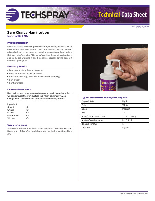
Zero Charge Hand LotionProduct# 1702Product DescriptionImproves contact between personnel and grounding devices such as wrist straps and heel straps. Does not contain silicone, lanolin, mineral oil and other materials found in conventional hand lotions that can interfere with PCB manufacturing. Blend of moisturizers, aloe vera, and vitamins A and E penetrate rapidly leaving skin soft without a greasy film.Features / Benefits•Improves wrist and heel strap contact•Does not contain silicone or lanolin•Non-contaminating / does not interfere with soldering•Non-greasy•NonflammableSolderability InhibitorsHand lotions from other manufacturers can contain ingredients thatwill contaminate the work surface and inhibit solderability. Zero Charge Hand Lotion does not contain any of these ingredients.IngredientGlycerin NOGrease NOLanolin NOMineral Oils NOSilicone NOUsage InstructionsApply small amount of lotion to hands and wrists. Massage into skin. Use at start of day, after hands have been washed or anytime skin is dry. Typical Product Data and Physical PropertiesPhysical state: LiquidColor: WhiteOdor: PleasantpH: 7.2Boing/condensation point: 212ºF (100ªC)Melting/freezing point: 32ºF (0ªC)Relative density: 1Shelf life: 5 yearsRev. A (08/18) Page 1 of 2800-858-4043 • Zero Charge Hand LotionProduct# 1702Packaging and Availability1702-8FP 8 oz liquid1702-G 1 gallon liquidEnvironmental PolicyTechspray® is committed to developing products to ensure a saferand cleaner environment. We will continue to meet and sustain theregulations of all federal, state and local government agencies.ResourcesTechspray® products are supported by global sales, technical andcustomer services resources.For additional technical information on this product or otherTechspray® products in the United States, call the technical salesdepartmentat800-858-4043,********************************our web site at: .Important Notice to Purchaser/User: The information in thispublication is based on tests that we believe are reliable. The resultsmay vary due to differences in tests type and conditions. Werecommend that each user evaluate the product to determine itssuitability for the intended application. Conditions of use are outsideour control and vary widely. Techspray’s only obligation and youronly solution is replacement of product that is shown to be defectivewhen you receive it. In no case will Techspray® be liable for anyspecial, incidental, or consequential damages based on breach ofwarranty, negligence or any other theory.Rev. A (08/18) Page 2 of 2North America Techspray®8125 Cobb Center Drive Kennesaw, GA 30152 800-858-4043********************EuropeITW Contamination Control BVSaffierlaan 5, 2132 VZ HoofddorpThe Netherlands+31 88 1307 400***************Countries outside the USCall to locate a distributor in yourcountry。
3M Loop Fastener SJ3527N 产品说明书
ASK A 3M EXPERTApril, 20143M™ Loop Fastener SJ3527NProduct Description3M™ Hook and Loop Fasteners o er advanced closure alternatives to zippers, screws, snaps, hooks andmore. They o er greater design exibility, faster product assembly, smoother and cleaner exterior surfacesand improved product performance in many applications. 3M hook and loop fasteners consist of hooks andloops which engage to form a quick fastening attachment. Simply pull the strips apart by hand to disengage.Product FeaturesThe woven nylon hook has exible, self-supporting inverted j-hooks protruding up from the backing withapproximately 300 hooks per square inch (46 hooks/square cm). The woven nylon loop has thousands of soft,pliable napped loops protruding above the backing, providing for thousands of openings and closings (cycles).Both the hook and loop are preshrunk to insure maximum dimensional stability and atness. Standard colorsavailable are black, white and beige, with several custom colors available with extended delivery times andadditional costs.SJ3527N loop is coated on the backside with a high performance rubber based pressure sensitive adhesivewhich allow for easy and convenient attachment to a variety of substrates, including low surface energyplastics.Commonly paired with 3M™ Hook Fastener SJ3526N, this loop fastener can also engage with other 3M™Hook Fasteners.Technical Information NoteThe following technical information and data should be considered representative or typical only and should not be used for speci cation purposes. Typical Physical PropertiesThickness Test Condition3.2 mm125 mil Unmated without liner0.33 mm140 mil Mated without linerProperty: Thicknessnotes: Using 1/2" pressure foot with 34 gram weightProperty ValuesMaterial Loop- Woven NylonBacking High Performance rubber based PSALiner Polyethylene with red printingLiner Thickness0.08 mm 3 milLiner Color WhiteWeight0.063 g/cm²0.015 oz/in²Typical Performance CharacteristicsProperty Values Substrate NotesDynamic Tensile7.6 N/cm²11 lb/in²Nylon Hook to NylonLoopRun at 12 inches per minuteDynamic Shear15.2 N/cm²22 lb/in²Nylon Hook to NylonLoopRun at 12 inches per minuteCleavage Strength13.1 g/cm width7.5 lb/in width Nylon Hook to NylonLoopT-Peel Adhesion 3.5 g/cm width 2 lb/in width Nylon Hook to NylonLoopRun at 12 inches per minute90° Peel Adhesion 3.9 g/cm width 2.2 lb/in width Nylon Hook to NylonLoopRun at 12 inches per minuteCycle Life5000Nylon Hook to NylonLoop Number of closures before losing 50% of original strengthTypical Performance Characteristics (continued)Product Performance:Additional Informationnotes: This guide should assist you in determining which product will adhere best to your substrate for.Handling/Application InformationDirections for UseAttachment TechniquesThe following information is intended to assist the designer considering the use of 3M hook and loop fasteners. System product performance depends upon a number of factors, including the fastener (material, adhesive and area), application method, surface characteristics (material, texture and cleanliness), environmental conditions (moisture, ultraviolet and temperature exposure) and the time it is expected to support a given load. Because many of these factors are uniquely within the user’s knowledge and control, it is required that the user evaluate 3M products to determine whether they are t for a particular purpose and are suitable for the user’s substrates, method of application and desired end use.Rounding the corners, slightly recessing the product into the substrate, or providing raised edges around the Reclosable fastener can reduce the possibility of edge lifting and improve the overall appearance of the fastener on the nished product. Mechanically securing the corners of the fastener with rivets, staples, screws, etc. may also reduce the possibility of edge lifting, but may reduce the closure performance.The two most common techniques for attaching these 3M hook and loop fasteners to various surfaces are summarized below.Pressure Sensitive Adhesive Attachment: The use of pressure sensitive adhesives eliminates or reduces the need for sewing, solvent activation, dielectric or ultrasonic bonding or bulk adhesive bonding. This can result in simplicity, improved safety and lower installation costs. Pressure sensitive adhesive products can be applied manually or automatically using a variety of equipment choices. Contact your 3M Sales Representative to discuss automated equipment options.Surface Preparation: Highly textured surfaces may reduce the ultimate adhesion levels and care should be given to minimize the surface texture or roughness. Adhesive backed fasteners should be applied to surfaces that are clean, dry and free of oil, grease, dust, mold release agents or surface contaminants that could reduce the adhesion. It is recommended to remove any surface contaminants that may reduce adhesion by using a method suited for the type and quantity of surface contaminants present. Isopropyl alcohol is a good general use solvent for cleaning contaminants from surfaces for example.In exceptional cases, especially when removing silicone mold release agents or on rough, porous surfaces, it may be necessary to lightly abrade the surface, use an adhesion promoter, or surface sealer to optimize the adhesive bond to the substrate. The selection of abrasion, priming or sealing methods will depend upon the substrates and the environmental conditions the product will be exposed to during use.Attachment Procedure: To obtain optimum bond to any surface, both the fasteners and the target surfaces should have equilibrated for a minimum of one hour at temperatures between 68°F (20°C) to 100°F (38°C) before application. The liner protecting the adhesive is removed and preferably without touching the adhesive, the fastener is applied to the substrate. Exposure of the adhesive to ambient conditions without the protective liner, before applying to the surface, should be minimized as initial adhesive tack may decrease. Flexible materials should be lying on a hard at surface so as to permit uniform adhesive contact with the surface. Use of a rubber hand roller, press platen or similar device is recommended to ensure full adhesive contact or wet- out with the substrate surface. Approximately 4.5 pounds of force per square inch, (310 grams per square centimeter) is recommended to increase adhesive contact, improving bond strength. For all adhesive applications, it is important to ensure that the edges are rolled down to reduce the chance of edge lifting.Plain backedThe plain backed 3M hook and loop fasteners are most commonly sewn into their applications. Liquid or hot melt adhesives and staples are other forms of attachment that can be utilized.Sewing: Although the selvedge edge was initially developed for stitching on, customers often nd that they get better anchorage when stitching through the 3M hook and loop portions of the fastener – this may be application dependent. The type of thread and stitch type is also best determined based on individual application, however, the fastener should be stitched on all edges for the best seam strength. Typically, special machine adjustmentsare not necessary when using our 3M hook and loop fastenersStorage and Shelf LifeShelf Life when stored in original packaging at 72°F (22°C) and 50% RH is 18 months.Trademarks3M is a trademark of the 3M Company.Family GroupReferencesISO Statement Technical Information SJ3401SJ3522SJ3523SJ3526N SJ3527N SJ3402SJ3531SJ3571SJ3572SJ3532N SJ3533N SJ3530Thickness (mm)Test Condition: Unmatedwithout liner2 2.4 3.2 2.4 3.22 3.2 3.2 2.4 2.03 3.05 2.4Thickness (mm)Test Condition: Matedwithout liner3.10.330.330.330.33 3.10.330.330.33 3.3 3.30.33Material Loop-WovenNylon Hook-WovenNylonLoop-WovenNylonHook-WovenNylonLoop-WovenNylonHook-WovenNylonLoop-WovenNylonLoop-WovenNylonHook-WovenNylonHook-WovenNylonLoop-WovenNylonHook-WovenNylonBacking NoAdhesive Sewon Plasticizerresistant acrylicPSAPlasticizerresistant acrylicPSAHighPerformance rubberbased PSAHighPerformance rubberbased PSANoAdhesiveSewonGeneralPurposerubberbasedPSAHighPerformanceAcrylicPSAHighPerformanceAcrylicPSARubberbased PSARubberbased PSAGeneralPurposerubberbasedPSALiner None Nonprintedpolyolen lm Nonprintedpolyolen lmPolyethylene withredprintingPolyethylene withredprintingNone PolypropylenePolyolen withembossed 3MlogoPolyolen withembossed 3MlogoWhitePolypropyleneWhitePolypropylenePolypropyleneLiner Thickness (mm)0.0890.0890.080.080.080.10.10.080.080.08Liner Color Clear Clear White White White Clear Clear White1. Product PageUrl: https:///3M/en_US/company-us/all-3m-products/~/3M-Loop-Fastener-SJ3527N?N=5002385+3293241230&rt=rud2. Safety Data SheetUrl: https:///3M/en_US/company-us/SDS-search/results/?gsaAction=msdsSRA&msdsLocale=en_US&co=ptn&q=SJ3527NThis Industrial Adhesives and Tapes Division product was manufactured under a 3M quality system registered to ISO 9001: 2000 and ISO/TS 16949:2002 standards.The technical information, recommendations and other statements contained in this document are based upon tests or experience that 3M believes are reliable, but the accuracy or completeness of such information is not guaranteed.Product UseWarranty, Limited Remedy, and Disclaimer Limitation of LiabilityIndustrial Adhesives and Tapes Division 3M CenterSt. Paul, MN 55144-1000800-362-3550 Please recycle.© 3M 2018. All Rights Reserved.The brands listed above are trademarks of 3M.Many factors beyond 3M’s control and uniquely within user’s knowledge and control can a ect the use and performance of a 3M product in a particular application. Given the variety of factors that can a ect the use and performance of a 3M product, user is solely responsible for evaluating the 3M product and determining whether it is t for a particular purpose and suitable for user’s method of application.Unless an additional warranty is speci cally stated on the applicable 3M product packaging or product literature, 3M warrants that each 3M product meets the applicable 3M product speci cation at the time 3M ships the product. 3M MAKES NO OTHER WARRANTIES OR CONDITIONS, EXPRESS OR IMPLIED, INCLUDING, BUT NOT LIMITED TO, ANY IMPLIED WARRANTY OR CONDITION OF MERCHANTABILITY OR FITNESS FOR A PARTICULAR PURPOSE OR ANY IMPLIED WARRANTY OR CONDITION ARISING OUT OF A COURSE OF DEALING, CUSTOM OR USAGE OF TRADE. If the 3M product does not conform to this warranty, then the sole and exclusive remedy is, at 3M’s option, replacement of the 3M product or refund of the purchase price.Except where prohibited by law, 3M will not be liable for any loss or damage arising from the 3M product, whether direct, indirect, special, incidental or consequential, regardless of the legal theory asserted, including warranty, contract, negligence or strict liability.。
Eaton 3SMini 3SM36 3SM36B 高级用户指南说明书
X²Eaton 3SMini3SM363SM36BAdvanced User GuideCopyright © 2021 EATONAll rights reserved.AUG_EATON-3SMINI_V03SMini EMEASpecial symbolsThe following are examples of symbols used on the UPS or accessories to alert you to important information:1.Table of contents1.Table of contents (3)2.Introduction (4)3.Presentation (5)4.Installation (6)4.1.Package contents (6)4.2.Safety (7)4.3.Power supply cord / socket (8)4.4.Start UPS (9)4.5.Voltage setup (10)4.6.Connect the equipment (12)5.Other functions (13)5.1.Turn OFF, turn ON (13)5.2.Display battery level (13)6.Troubleshooting (14)7.Technical specifications (16)8.Equipment care (17)9.Service and support (17)Thank you for selecting an Eaton product to protect your equipment.The Eaton 3SMini range has been designed with the utmost care. We recommend that you take the time to read this advanced user guide and documentations provided to take full advantage of the many features of your UPS (Uninterruptible Power System).Before installing your Eaton 3SMini, please read the information and safety instructions provided. Follow the instructions in the quick start guide and if necessary, refer to this advance user guide.To discover the entire range of Eaton products, we invite you to visit our web site at or contact your Eaton representative.The Eaton 3SMini Uninterruptible Power System (UPS) is designed for small electrical such as, but not limited to, Internet gateways, switches or routers, IP cameras etc. It must not be used to supply other electrical equipment (lighting, household appliances, etc.). It prevents your critical equipment from power failures and power surges.Barrel adaptor polarity:Note: Extended replacementkit can be ordered throughyour local customer serviceeaton.eu/3SMiniapproach (/productstewardship).4.4.Start UPSDo not connect load until the voltage has been appropriately setup (see 4.5) Press the ON/OFF button for three seconds. The battery level is first displayed for five seconds then the LED indicates the output voltage level (default 12V):Figure 2 Start UPSBattery levels:Slow blinking LEDFast blinking LEDFigure 3 Battery levels4.5.Voltage setupBefore entering voltage setup, ensure that the protected equipment is disconnected from the UPS:Figure 4 Disconnect the equipmentThen enter voltage setup mode and select the appropriate output DC voltage corresponding to equipment nominal input voltage (9V, 12, 15V or 19V): •Press the ON/OFF button (5) for eight secondsImportant: The LED and UPS will briefly shut down (OFF to 0V) during the process and it will turn off any connected equipment, just keep pressing the button until eight seconds have passed. When LED start flashing (slow), release the button.•You can then cycle through the different LED position which indicate the voltage output by pressing the ON/OFF button (quick press).Note that the voltage is not active until the selection is confirmed.Figure 5 Cycle through the voltage levels•Once the voltage is selected, then simply press eight seconds to confirm the choice. The LED will stop blinking and steady itself.The DC output is now delivering the new voltage.connectorYour equipment is now backed-upInternal failureKeeps blinking for 20 seconds then enters shutdown modeThe unit needs replacement. Contact your customer service.Problem Possible cause ActionAll LED are OFF The UPS is turned OFF Press 3s the ON/OFF button.UPS does not start This could be linked toinitial state (out-of-box) Make sure that the UPS is plugged in a wall outlet that delivers power and press three seconds the ON/OFF button.If this does not work, contact your local customer service.One LED remainsOFF when UPS isfully charged, andbattery leveldisplayedLED is defective Contact your local customer service.UPS does not charge Power is not delivered toUPS or batteries may bedefective1) Ensure that charging is notinterrupted.2) Check mains are delivering power.3) Check that the input cord is wellplugged in the UPS.4) Contact your local customer service.Load is not powered UPS is in Auto-Recovery(AR) modeUnplug the equipment.1) Verify load electrical characteristics(voltage, power).2) Let the UPS cool down (keep deviceaway from any heat source).Wait several minutes and try again.UPS is frozen and ON/OFF button is ineffective UPS is locked Disconnect equipment, turn OFF UPSand unplug it from mains.Wait a minute and reconnect UPS.Turn it back ON.Other option: Reset to factory settings:press 15 seconds from the OFF state(unplugged). Then plug UPS andrestart UPS.7.Technical specificationsT e chnical specificationsTechnical specificationsAC Input voltage 100-240V~ ACAC Input current CEE7/7 (FR/DIN): 1.6ABS 1363: 1.6AInput frequency 50/60HzOutput voltage/Amps 9V/3A12V/3A15V/2,4A19V/1,89AOutput connection Barrel adaptors 5,5 x 2,55,5 x 2,14,75 x 1,73,5 x 1,35Power rating 36WBattery type Li-Ion x2 (ICR18650)*Cell weight: 45g MaxBattery capacity 3,7 V/2200mAh (x2)UPS dimensions (W x H x D) 95,5 x 30 x 136 mmUPS weight 0,4 kgOperating temperature 0 - 35°cSafety IEC 62477-1, CE mark, CB report EMC IEC 62040-2Performance IEC 62040-5-3Warranty 2 years* Typical full charge time (may vary): ~4hPart number Input cord3SM36 FR/DIN (1m long)3SM36BS BS1363 (1m long)。
3M UDC-HV Sensitized Emulsion 说明书

MATERIALESSE REQUIERESE RECOMIENDA Insoladora Cabina de secadoPila de lavado Pistola de agua a presión Área de trabajo limpia Calculadora de exposición de Espátula de aplicación ChromalineQUIMICOSSE REQUIERE SE RECOMIENDAChroma/Cle an™ Chroma/Haze ™desengrasantelimpiador de imagen fantasmaChroma/Strip™Chroma/Fill™recuperador de pantallasbloqueador de pantallasSEGURIDAD Y MANEJOEvite el contacto con la piel y los ojos. Para mayorinformación, consulte el documento MSDS (hoja deinformación sobre seguridad en el manejo de materiales).ESPECIFICACIONESApariencia: PúrpuraInsolado: Rápida (vea el reverso)Sólidos: 35% (sensibilizado)Viscosidad: 5300 CPS (sensibilizado)Presentaciones: Cuarto, galón, 3.5 galones,caneca de 50 galonesALMACENADOLa emulsión UDC-HV sensibilizado tiene una vida útil de 3a 4 semanas a temperatura ambiente (60° a 80° F; 23° a31° C). Para aumentar al máximo la vida útil, utilice únicamente agua destilada para disolver el sensibilizador diazo.Se debe proteger contra la congelación. Congeladodurante el envio pueden aparecer grumos transparentes de textura gelatinosa, que pueden semejar pequeños agujeros.Emulsionado, pantallas no insoladas pueden ser almace nadas de un mes en un lugar limpio, fresco, seco y totalmente oscuro.Fecha Caducidad. Comprueba siempre la fecha de caduci-dad de la botella de diazo para asegurar el producto.MAGNA/CURE ® UDC-HVLas emulsiones UDC-HV de doble curado estándeseñadas para una amplia variedad de aplicaciones en la reproducción de imágenes. UDC-HV le ofrece estos beneficios adicionales:• Rápida exposición, con una calidad de imagenexcelente• Esténciles fuertes y durables, resistentes a una gran variedad de tintas y aditivos • Superior adherencia a la malla• La alta viscosidad permite poner las capas en mallas de alto o bajo conteo• Lavado extra rápido y fácil recuperaciónCon la emulsión directa UDC-HV , los fabricantes de las pantallas obtienen imágenes de extraordinaria calidad y esténciles excepcionalmente durables. Además, la alta viscosidad de la emulsión UDC-HV permite que ésta sea aplicada en pantallas de malla de alto o bajo conteo.Para ser utilizada con tintas base agua, solvente, cosovente UV y plastisol.E M U L S I O N D I R E C T A D EF O T O P O L I M E R O P U R OProductos de Impresión de Pantallas Chromaline4832 Grand Ave. • Duluth, Minnesota 55807 • Tel: 218-628-2217 • Fax: 218-628-3245Sitiointernet:•Correoelectrónico:********************UNA COMPAÑÍA IKONICS CERTIFICADA ISO 9001 ÍNDICE NASDAQ: IKNXADVERTENCIA: Este producto puede exponerle a químicos incluyendo 1,4-dioxane, que es (son) conocido (s) por el Estado de California como causante (s) de cáncer. Para mayor información, visite 180801INSTRUCCIONESDESENGRASADOUsando desengrasante Chroma/Clean™enjabona ambos lados del tejido. Frota la pantalla y luego enjuaga con una manguera tipo jardín, luego seca.MEZCLAMezclar la emulsión y el sensibilizador acorde a las instrucciones del bote. Deja la emulsion en reposo 2horas antes de su uso.EMULSIONADOEmulsiona a temperatura ando una raedera de emulsionar,aplica una primera capa en la cara de impresión. Después, trabaje el lado sobre el que corre el rasero, aplicando de una a tres capas, dependiendo si desea un esténcil de mayor espesor.Si necesitar espesorar aplica capas adicionales a la cara de impresión,después del primer secado del esténcil. Haz secado entre capas.SECADOSeca la pantalla horizontalmente la cara de impresión hacia abajo, usa una cabina de secado oscura ylimpia. La Temperatura no debería deexceder de 110ºF(43ºC).INSOLADOPon la cara de la emulsión delfotolito en contacto con la cara de impresión de la pantalla.REVELADORocía suavemente ambos lados de la pantalla con agua tibia, espera 30segundos luego enjuaga suavemente la cara de impresión hasta que la imagen se abra. Enjuaga ambas caras completamente. Deje sacar la pantalla completamente antes de imprimir.RECUPERADOAplica Chroma/StripTM recuperador de pantallas en ambos lados.Restriega con una brocha de nylon para asegurar que la superficie este húmeda; deja el trabajo unos momentos hasta queempiece a disolver. Elimina elresiduo con agua a presión, luego enjuaga con una manguera tipo jardín completamente.LINEAS GUIA PARA EL INSOLADONota: Utilice los tiempos dados como guías. Usa la calculadora de exposición de Chromaline paradeterminar los tiempos óptimos de exposición. Los tiempos individuales pueden variar de acuerdo con el equipo usado, vida de la lámpara y demás condiciones de trabajo.TIEMPOS MINIMOS SUGERIDOS DE EXPOSICION MallaTiempo mj/cm 2 158 / pulgada 60 - 90 seg. 379 - 55662 / cm230 / pulgada 45 - 60 seg. 253 - 37990 / cm305 / pulgada30 - 45 seg.165 - 253120 / cmLos tiempos de exposición fueron determinados para una unidad de 5 KW a una distancia de 42 pulgades. (107 cm) de marco. La malla era de color amarillo. Las pantallas fueron cubiertas húmedo en húmedo una vez del lado de la impresión y dos veces del lado del rasero.ENVITE LAS FALLAS: Las emulsiones de doble curado tienen una latitud de exposición muy amplia. Es común que los esténcilessubexpuestos parezcan aceptables a simple vista, pero es probable que se resquebrajen prematuramente una vez dentro de la impresora.Para determinar la velocidad de exposición, empiece siempre sobreexponiendo el esténcil de prueba y reduzca poco a poco el tiempo hasta que logre una calidad de imagen aceptable. Esto asegurará una buena durabilidad.Trabajar con luz amarillaPara Servicio TécnicoLlamada gratis al 1-800-328-4261Correo Electrónico:*******************Para Asistencia Téchnica Contacta su Distribuidor Local(Por fuera Norte América llame al + 1-218-628-2217)。
- 1、下载文档前请自行甄别文档内容的完整性,平台不提供额外的编辑、内容补充、找答案等附加服务。
- 2、"仅部分预览"的文档,不可在线预览部分如存在完整性等问题,可反馈申请退款(可完整预览的文档不适用该条件!)。
- 3、如文档侵犯您的权益,请联系客服反馈,我们会尽快为您处理(人工客服工作时间:9:00-18:30)。
3、故障指示灯为红色常 电压选择不正确 亮
3、能够听到充/消磁的 声音,但是在充磁动作 执行完后,磁条仍然不 能被激活,或者消磁动 作后,磁条不被消磁。
不正确的图书摆放方 式;
多本书同时放置在940 上
图书中有永久性磁针
检查电压选择开关,是否已经选择至 240V。 如果已经在 240V,问题依旧,拨打 3M 服 务电话。 使用正确的方式使用940。
图1 标签位置
3 图书馆系统
5
3M 图书馆系统 M940 系列充/消磁器 用户手册
3M™ BookCheckM 940 系列功能特性
3M BookCheck M 940系列是一个用户安装 的设备,它用来对保护图 书馆资料安全的3M™ Tattle-Tape™安全磁条进 行充磁和消磁。这个单元 可以放置在工作台面上或 者嵌入安装在书桌的里 面。由于可通过电脑借这 个单元来迅速处理借还, 这样馆员处理资料时不会 太疲劳。
为了减少由于用户或承包人/安装者造成的BookCheck系统零件的错误安装带来的火 灾和电的危险, 或者危险发生时使用系统: 依照3MBookCheck Model 940系列位置图和安装指导上给出的说明和规范把系统零 件安装到桌面上或者护栏中; 护栏或者电源线发生危险时不要使用BookCheck系统。
3M 图书馆系统 中国上海兴义路8号,万都中心大厦38楼
/library
1
3M 图书馆系统 M940 系列充/消磁器 用户手册
安全信息
在安装和使用3M™ BookCheck Model 942之前,阅读, 理解, 然后遵从这些说明所包含的所有的安全信息. 保留这些说明以 便将来可以参考.
3M 图书馆系统 M940 系列充/消磁器 用户手册
图书馆专用充消磁器 Model 940 系列
用户手册
© 2006 3M.版权所有. BookCheck Model 940 系列用户手册 78-8126-8471-6 Rev. A 中文版,第一版 3M和Tattle-Tape 都是3M的商标.
3 图书馆系统
用途
书籍验证 Model 942供馆员使用来进行登入和登出使用电磁 (EM) 标签的图书馆资料.它可以在台式电脑上使用或者成为定 制的工作台面的组成部分。书籍 Model 942安装在指定的Book Check Series Model 940 计划位置图和安装指导中. 它指定在 室内或图书馆中使用且不作其他用途。
3 图书馆系统
3
3M 图书馆系统 M940 系列充/消磁器 用户手册
警告
CAUTION
为了减少由于对任何焊料中含有铅的电线的错误处置而带来的环境污染的危险: 在系统服务寿命快结束时,BookCheck单元和激光扫描枪附件的处置应符合国家,及当 地的规定。
为了减少由于有人窥视激光扫描枪附件而造成激光的暴露带来的危险: 请勿直视激光扫描枪附件; 在系统服务寿命快结束时,激光扫描枪附件的处置应符合国家,及当地的规定。
3 图书馆系统
12
3M 图书馆系统 M940 系列充/消磁器 用户手册
获得技术支持与服务
3M 中国免费售后服务热线 800-820-3312
系统信息
当您来电时, 请提供位于设备底部的系统的型号和序列号 型号: ___________________________________________ 序列号: __________________________________________
3M 图书馆系统 M940 系列充/消磁器 用户手册
图 4 电压选择警告明
概览
3M 图书馆系统 M940 系列充/消磁器 用户手册
图 5 面板总览
关于磁性媒体模式
当进入磁性媒体模式时,为了保护磁存储媒体。940设备的充 消磁磁场将被关闭, 因为磁性媒体易受磁场影响而受到损害。 当你想要处理非磁性物品时请确保940的磁性媒体模式已经关 闭,普通处理模式已经打开。
为了减少由于用户或承包人/安装者造成的BookCheck系统零件的错误安装带来的火 灾和电的危险: 依照3M BookCheck Model 940系列位置图和安装指导上给出的说明和规范把系统零 件安装到桌面上或者护栏中。
为了减少由于保养部分的错误安装或者是使用了没有经过认可的零件替代品而带来的 火灾和电的危险: 请勿试图修改或维修 — 没有用户可以独自解决的部分 — 与3M 联系得到维修服务。 使用3M认可的系统零件, 仅由3M服务人员安装.
可能原因
解决方法
机器后插座旁的电压选 调整电压选择开关至240V(中国)
择不正确。
2、开机时,故障指示灯 闪烁
没有电源输入;
电源线插座松动; 机器上电源线插头松 动; 挡住了红外开关; 红外感应开关脏污;
检查并确定各电源线插头连接可靠。打 开电源。
正确使用,并触发红外开关; 用软布清洁红外开关表面,请勿使用任 何化学清洁剂。
功能特性包括以下几点:
通过馆员来有效地登 入或登出图书馆中的资 料。
可选择的处理流程, 从右到左或者从左到右。
有声反应, 登入或者 登出的操作已经完成会有 “呯”地一声来提示馆员。
安全磁条状态验证,当 检测到一个激活的安全磁 条时会出现一圈光亮来提 示馆员。
人性化的指示图标和 按钮的操作都很简便。
图2 BookCheck M 940 系列
关于磁性验证灯
当启动时,验证器指示灯亮当设备检验到一条激活的安全磁条。
3 图书馆系统
9
处理书籍
这个程序描述了如何进行充磁/消磁操作。
1、使用方向按钮, 来选择从左至右或 者从右至左的操作 方向。
2、确认940系统工 作在普通工作状 态,如果磁媒体模 式知识灯亮,请关 闭磁媒体模式。
3M 图书馆系统 M940 系列充/消磁器 用户手册
3M 图书馆系统 M940 系列充/消磁器 用户手册
图 7 关闭图书安全验证指示灯
故障排除
大多数的故障排除任务都可以由受过训练的技术人员完成。但 是这部分仍然提供了一些故障排除的程序,你可以自己解决一 些问题。
图 8 故障排除
3 图书馆系统
11
3M 图书馆系统 M940 系列充/消磁器 用户手册
故障现象 1、没有电源输入
标志的描述
代表了一个具有潜在危险的情况, 如果不加以避免将会导致严重的伤害和/
DANGER: 或财产损失。
代表了一个具有潜在危险的情况, 如果不加以避免将会导致严重的伤害和/
WARNING: 或财产损失。
代表了一个具有潜在危险的情况, 如果不加以避免将会导致严重,轻或中等
CAUTION: 的伤害和/或财产损失。
CAUTION:
代表了一个具有潜在危险的情况, 如果不加以避免将会导致财产损失。
产品安全标签符号的描述
注意: 阅读附带文件
电击危险 放置危险
3 图书馆系统
2
3M 图书馆系统 M940 系列充/消磁器 用户手册
警示
WARNING
为了避免由于用户或承包人/安装者试图保养或维修BookCheck系统时带来火灾和电 的危险: 请勿试图修改或维修 — 没有用户可以独自解决的部分 — 与3M 联系得到维修服务。
a、如果验证指示灯的工作状态指示灯没有亮,请按指示灯 开关
b、将图书放置在操作台面上,盖住其中一个感应开关,左 右移动图书若干厘米的范围(盖着感应开关),如果磁性验证 灯点亮,说明磁条已经被激活。
3 图书馆系统
10
关闭验证器
这部分讲述了怎样关闭验证功能
1 如果验证器指示 灯是亮着的,就按 钮来关闭这个功 能。
为了减少因为重复提起图书馆资料而造成的重复性劳损而带来的危险: 这个产品的运作涉及到重复的身体动作. 为了将重复性劳损的可能性减到最低, 避免延 长重复的动作, 当开始疲倦时就休息, 当可能时, 与其他人员交换工作,避免拿够不到的 物品。
3 图书馆系统
4
标签位置
3M 图书馆系统 M940 系列充/消磁器 用户手册
3 图书馆系统
6
3M 图书馆系统 M940 系列充/消磁器 用户手册
稳定性要求
不要将BookCheck M 940 系列设备放置在上不符合 Underwriters Laboratories Inc.稳定性标准的家具. 确保家具符 合下列UL标准: 60950 (南美) EN60950 (欧洲) IEC 60950 (南美和欧洲以外的国家)
磁媒体介质警告
BookCheck Model 940 系列设备不可用于磁性媒体的充消磁。 使用940对录音带,录像带,信用卡以及电脑软盘进行处理, 会造成其中存储的数据丢失。
图3 磁性媒体警告
3 图书馆系统
7
电压选择警告
使用前请检查电压 选择按钮。
确保3M™ BookCheck Model 940 系列设备设置 到了正确的工作电 压(115V或者 240V). 这个设备 出厂时设置的是 240V.
错误的触发开关。
请检查系统是否处在Magnetic media 模 式
检查图书资料是否触发了正确的感应 器,方向模式不同,触发开关也不同。
6没有任何指示灯亮,但 是确定系统电源连接可 正常。
拨打3M 服务电话。
警示 : 如果故障原因无法确定,请联系 3M 技术工程师寻求帮助。设备内有高压,请勿擅自打 开机器设备。只有受过培训的 3M 技术工程师才可打开机器。
一次操作只在940上放一本图书。
取出图书中的永久性磁条
4、磁性指示灯不指示 磁性指示灯未打开
将磁性指示开关选择至“ON”一档
940工作面上所摆放的 检查图书是否安装了磁条; 图书没有安装磁条,或 给图书执行充磁操作; 其中的磁条没有磁性
5、尽管故障灯不亮,但 Magnetic media 模 是系统还是没有充/消 式. 磁的声音
