EMA-R2危险液体检查仪用户手册范本
韩国便携式危险液体检查仪操作说明书
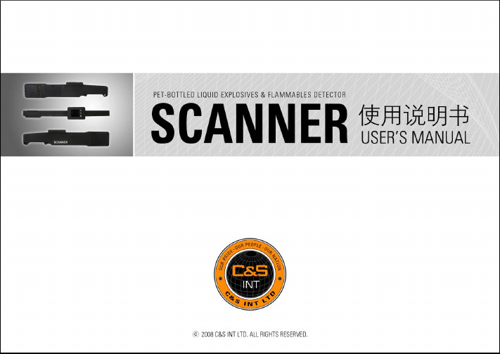
SCANNER 使用说明书SCANNER 目录•概要•构成•Components •充电•电源开/关•待机•画面上方各种图•开关警报音•开/关闪光灯•画面亮度调•时钟设置•系统初始化•操作方法•注意事项•规格与特征1. 简单的操作无需任何特殊的操作,只需简单扫描便可测试出目标物液体的安全性。
2. 安全性高本设备是通过GPR(Ground Penetrating Radar)微波对于目标物进行识别,因此不会像X射线等放射线及化学物质那样对人体造成危害性。
3. 精确快速的识别由于通过微波射入对物质内部进行分析,因此即使目标物的量较少,也可正确快速地进行识别。
且由于使用了优秀的CPU,因此可在1秒钟之内完成分析。
4. 节约人力资源无需为检测投入特殊人员,最大地节省人力资源。
Scanner1[2] 箱子[3] 腰带变压器钥匙链2345ComponentsSCANNER检测开关充电SCANNER ※当插入变压器进行充电时,画面上方出现充电的图标,并出现充电中的文字显示,之后消失。
SCANNER1. 打开电源,设备将开机。
2. 开机成功 3. 开机失败:需重新开机或点击初始化。
电源开/关SCANNER待机运行时约10 秒钟后重新运行按任意键Power Save Wake Up1243SCANNER显示电量表示警报音关闭表示警报音开启表示闪光灯关闭表示充电中表示闪光灯开启画面上方各种图SCANNER开关警报音开警报关警报1.在待机画面中点击菜单键1.在待机画面中点击菜单键2.通过上下键选择警报音2.通过上下键选择警报音3.点击菜单键3.点击菜单键4.警报音开启出现ON图标4.警报音关出现OF F图标SCANNER开/关闪光灯1.在待机画面中点击菜单键1.在待机画面中点击菜单键2.通过上下键选择闪光灯2.通过上下键选择闪光灯3.点击菜单键3.点击菜单键4.闪光灯关闭出现OFF图标4.闪光灯开启出现O N图标开闪光关闪光SCANNER1.在待机画面中点击菜单键2.通过上下键选择画面亮度3.点击菜单键4. 通过上下键,将亮度由1~5自由选择6.点击菜单键确认画面亮度调SCANNER 时钟设置1.在待机画面中点击菜单键2.通过上下键选择画面亮度3.点击菜单键4. 通过上下键,调整数字5.通过点击菜单,进入下一个数值的输入6.在输入完最终数值后,点击菜单进行确认7.设置完成后,将回到初始画面SCANNER1.在待机画面中点击菜单键2.通过上下键选择系统初始化4.初始化中3.点击菜单键5.初始化失败7.回到初始画面 6.初始化成功7.回到初始画面初始化系统初始化SCANNER 操作方法非易燃物易燃物将被检测物放置于传感器中心部,按探测按钮。
EMA-R2危险液体检查仪用户手册
危险液体检查仪启亚CHIAEMA-R2用户说明书手册导读注意事项本手册作为公司生产之EMA-R2液体检查仪使用说明书及日常维护参考文档,仅供在使用EMA-R2液体检查仪时参考使用。
请严格按照说明书提示之方法进行操作,避免人为过失带来之损害。
对于说明书未提及之操作流程及方法,请咨询本公司售后技术支持人员。
本文所提及的技术参数为产品实验数据,仅供参考,具体参数请参照合同之描述。
如碰到与书中内容不相符的情况并影响到该产品的使用和维护,请及时与本公司联系。
以免因此造成的不必要的人身和财产伤害。
在您收到本公司产品后,请先对照本手册的产品清单,对您的产品进行核对,在确认无误后,再进行使用。
在您使用本公司产品前,请务必仔细阅读本书,并留意书中要点,以避免人为操作不当造成的经济财产损失。
本产品具体保修范围以及保修年限参照合同之描述。
本文所使用之图片与描述未经允许不得进行转载使用。
特殊标示符号禁止警告:该警告表示禁止不当行为及操作事项,防止不当操作所造成的伤害。
危险警告:该警告表示不当操作可能会对用户造成财产及人身伤害。
特别提醒警示用户,有此图标部分务必重点阅读。
并谨记在心。
允许说明:该说明表示允许的操作状态,以及名词解释,一般注意事项,使用常识,参考信息等。
目录产品清单 (5)1.产品概述 (6)1.1应用领域 (6)1.2技术特点 (6)2 产品使用说明 (7)2.1产品使用注意事项 (7)2.2 产品结构说明 (8)2.3产品功能及应用 (9)3产品维护及保养 (10)4常见故障与解除方法 (11)5附录 (12)5.1使用日志 (12)5保险单 (13)产品清单内容样图数量探测仪本体 15号干电池 2防静电手套 1使用说明书 11产品概述1.1应用领域该液体检查仪是一款便携式手持液体检查仪,能在较短时间内分辨出密封容器内的液体是否为易燃、易爆等危险性液体。
该设备中不包含任何放射性以及任何其它有潜在危险的元素。
液体压力治疗仪操作规程

液体压力治疗仪操作规程1. 操作规程的目的本操作规程旨在确保液体压力治疗仪在使用过程中的正确操作,以提供安全有效的治疗。
2. 适用范围本操作规程适用于液体压力治疗仪的操作人员,包括医疗专业人员和训练有素的操作人员。
3. 操作步骤3.1 准备工作1. 检查液体压力治疗仪是否处于正常工作状态,如有故障或异常现象应立即报修。
2. 确保治疗仪所需的治疗液体已准备就绪,包括液体的种类和所需的数量。
3. 准备消毒材料,确保操作环境的卫生和安全。
3.2 操作液体压力治疗仪1. 佩戴个人防护装备,包括手套和口罩。
2. 打开液体压力治疗仪的电源开关,并等待系统自检完成。
3. 将治疗液体连接到液体压力治疗仪的输入接口。
4. 设置液体压力治疗仪的治疗参数,如液体流量和治疗时间。
务必按照医生或使用说明的要求进行设置。
5. 确认治疗参数设置正确无误后,按下开始按钮开始治疗。
6. 在治疗过程中,密切观察液体压力治疗仪的工作状态,如发现异常情况应及时停止治疗并报告相关负责人。
7. 治疗结束后,关闭液体压力治疗仪的电源,并拆除治疗液体连接管路。
8. 使用消毒剂对液体压力治疗仪的接口、管路等进行消毒处理。
9. 清理操作区域,确保无废弃物和污染物残留。
3.3 特殊注意事项1. 操作人员在操作液体压力治疗仪之前应接受相关培训,熟悉其使用方法和安全注意事项。
2. 在操作过程中,严禁将非治疗液体接入液体压力治疗仪,以免损坏设备或引发风险。
3. 建议定期维保液体压力治疗仪,确保设备的正常运行和安全可靠。
4. 紧急情况处理任何紧急情况发生时,操作人员应立即停止操作,并按照应急预案采取相应的措施。
在紧急情况处理完毕后,应报告相关负责人并进行事故原因分析。
5. 操作规程修订本操作规程需要根据实际情况进行定期检查和修订,以确保其与液体压力治疗仪的实际操作方式一致。
6. 附录无。
美高尔的自动实验室油液测试设备说明书
DESCRIPTIONMegger’s automatic laboratory oil test sets perform accurate breakdown voltage tests on mineral, ester and silicon insulating liquids. Moulded test vessels give repeatable results with lock in precision electrode gap setting adjustment wheels. The transparent, shielded lid and large test chamber enable easy access to the test vessel.All three laboratory models are fitted with a 12 key alpha-numeric keypad to facilitate entry of test ID, filenames, notes etc. Alphacharacters are entered by repetitive pressing on a key, the same way as text is entered modern cellular telephones.Test standards are preloaded in the instrument and new versions can be uploaded via USB flash drive. All laboratory models support the creation of user defined custom tests. Test results are identified either by a serial number or asset ID and are time and datestamped. Megger’s asset and data management software, PowerDB Lite, is bundled at no extra cost providing an excellent tool for downloading and printing results.An optional internal printer provides a hard copy of results. Inkbased printout ensures durability at all temperatures. USB interfaces (x3), USB flash drive, external USB printer and barcode scanner. User safety is paramount and Megger have designed independent and dual redundant high voltage cut-off circuitry to ensure safety. During a test the operator can terminate by pressing any button on the keyboard which will remove high voltage immediately and abort the test. The transparent lid provides ample visibility within the chamber yet is protected and electrically shielded by a screen with multiple links to instrument ground.APPLICATIONMonitoring and maintenance of oil quality is essential in ensuring the reliable operation of oil filled electrical equipment. Codes of practice have been established in many countries that include several different types of test on insulating oils.One of the fundamental tests of oil quality is the breakdown voltage test, which is a measure of the oil’s ability to withstand electric stress. A low breakdown voltage can indicate the presence of contaminants such as water or conducting particles.Care should be taken to ensure the process of sampling oil and subsequent testing does not in any way contaminate it with foreign objects. Cleaning vessels between oil tests should be a rinse with the next sample, never clean with fibrous materials. To ensure an accurate reading set gap carefully and lock adjusting wheels.FEATURES AND BENEFITS■■Test voltages : 60 kV , 80 kV and 100 kV ■■Lock in precision oil vessel - lockable gap setting■■Flat electrode gap gauges that will not damage electrodes ■■Automatic oil temperature measurement■■QVGA colour display with backlight visible in sunlight ■■Large, easy clean test chamber with oil drain ■■High visibility test chamber■■Safe operation with dual redundant micro switch ■■Intuitive user interfaceOTS100AF , OTS80AF and OTS60AFLaboratory oil testersOTS100AF , OTS80AF and OTS60AF Laboratory oil testers■■Laboratory instruments for measuringinsulating oil breakdown voltage■■Lock in precision - oil vessel with lockableadjustment■■Bright 3.5” colour display visible out doors ■■Suitable for mineral, ester and silicon oils ■■Trip detection circuit with direct measurementof voltage and current■■Ultra fast (< 10 μs) HV switch off timeOPTIONAL FEATURES■■Internal printer ■■Motorised lid impeller■■Voltage check unit (VCM100D/VCM80D)SPECIFICATIONS Test voltageOTS60AF 0 to 60 kV rms maximum (30 kV - 0 - 30 kV)OTS80AF 0 to 80 kV rms maximum (40 kV - 0 - 40 kV)OTS100AF 0 to 100 kV rms maximum (50 kV - 0 - 50 kV)Voltage resolution and accuracy0.1 kV °1% °2 digitsProgrammed test sequencesASTM D 1816-04 BS EN 60156-96 SABS EN60156ASTM D 877A-02 CEI EN 60156-95 VDE0370 part 5ASTM D 877B-02 IRAM 2341 AS1767.2.1IEC 60156-95 UNE EN 60156 PA SEV EN60156 NF EN 60156 JIS C 2101-99 (M) JIS C 2101-99 (S)plus 3 custom testsequencesVessels400 ml (standard) 150 ml (option)Nylon 12 chamber provides precision electrode alignment, adjustment wheels lock electrodes in position, option of 150 ml vessel for low volume oil samples Temperature measuring range10 °C to 65 °CTemperature sensor resolution 1 °C Power supply Line voltage 85 to 265 VAC Line frequency 50/60 HzInterfaceUSB 2.0 compatible2 x USB type-A (Flash drive, printer, other)1 x USB type-B (Factory use only)Internal printer(Option)Matrix impact printer Paper 57.5 mm wideExternal printer Any printer with USB interface and PCL3 driverProtection Dual safety micro switches on chamber coverDisplay320 x 240 QVGA colour display with backlight Operatingtemperature range and humidity0 °C to +50 °C 80% RH at 40 °CStorage temperature range and humidity -30 °C to +65 °C 95% RH at 40 °C Maximum altitude2000 mSafety Designed in accordance with IEC61010Dual safety micro switches on chamber coverEMC Light industrial IEC 61326-1 Class B, CISPR 22, CISPR 16-1 and CISPR 16-2Dimensions All models 580 mm x 420 mm x 290 mm Weight All models 30 kg with printer option fittedLanguageEnglish, French, German, Spanish,Chinese, Czech, Dutch, Finnish, Italian, Norwegian, Polish, Portuguese, Russian and SwedishO i l t y p e s t e s t e dE l e c t r o d e g a p o p t i o n s (m m )E l e c t ro de s h a p e o p t i o n s O i l s t i r r i n g o p t i o n s V o l t a g e r i s e r a t e o p t i o n sB r e a k d o w n t e s t s e q u e n c eS t a n d a r d s c o m p l i e d w i t h a n d p r o g r a m m e dM i n e r a l E s t e r H M W HS i l i c o n 1.02.02.52.540.5 k V /s 2 k V /s 3 k V /sN u m b e r o f t e s t sI n t i a l s t a n d t i m eT i m e b e t w e e n t e s t sI E C 60156-95■■■■■■■■■65 m i n s2 m i n sB S E N 60156-96■■■■■■■■■65 m i n s2 m i n sC E I E N 60156-95■■■■■■■■■65 m i n s2 m i n sI R A M 2341■■■■■■■■■65 m i n s2 m i n sU N I E N 60156■■■■■■■■■65 m i n s2 m i n sN F E N 60156■■■■■■■■■65 m i n s2 m i n sS A B S E N 60156■■■■■■■■■65 m i n s2 m i n sV D E 0370 p a r t 5■■■■■■■■■65 m i n s2 m i n sA S 1767.2.1■■■■■■■■■65 m i n s2 m i n sP A S E V E N 60156■■■■■■■■■65 m i n s2 m i n sJ I S C 2101-99 (M )■■■■■■5 x 22 m i n s1 m i nJ I S C 2101-99 (S )■■■■■1 x 52 m i n s (x 5)N /AA S T M D 1816-04■■■■■■■53 m i n s1 m i n 15sA S T M D 877A -02■■■■■■52 m i n s1 m i nA S T M D 877B -02■■■■■■1 x 52 m i n s (x 5)N /AC u s t o m t e s t s (x 3)(P r o g r a m m a b l e )■■1.0 t o 7.0■■■■■■0.5 k V /s t o 5 k V /s5, 6 o r 1010s t o 600s10s t o 600sP r o g r a m m e d t e s t s e q u e n c e o v e r v i e wExample of an ordering configuration:-OTS100AF-USA-P4 = This order is for an OTS100AF with US power lead, ASTM electrode set, internal printer and lid stirrer.UKArchcliffe Road Dover CT17 9EN EnglandT +44 (0) 1304 502101 F +44 (0) 1304 207342 ******************UNITED STATES4271 Bronze WayDallas TX 75237-1019 USAT 800 723 2861 (USA only)T +1 214 333 3201F +1 214 331 7399******************OTHER TECHNICAL SALES OFFICESValley Forge USA, College Station USA,Sydney AUSTRALIA, Danderyd SWEDEN,Ontario CANADA, Trappes FRANCE,Oberursel GERMANY, Aargau SWITZERLAND,Kingdom of BAHRAIN, Mumbai INDIA,Johannesburg SOUTH AFRICA, Chonburi THAILANDCERTIFICATION ISORegistered to ISO 9001:2008 Cert. no. Q 09290OTS100AF--OTS80AF--OTS60AF_DS_en_V09.pdfMegger is a registered trademarkDescription Order Code configured* OTS60AF configured* OTS80AF configured* OTS100AF Included accessories (on all configurations)Vessel 400 ml assemblyMagnetic bead stirrers (2 off)Magnetic bead retrieverUser manual CDPowerDB Lite softwareElectrode gauge set 1, 2, 2.5, 2.54 mm 1002-144 Configured accessories (to order additional or spares) OTS IEC60156 Electrode set contents- supplied in accessory case12.7 mm spherical electrodes (2)36 mm mushroom electrodes (2)Magnetic stirrer bar (2)Magnetic stirrer bar retriever (1)Gap gauge set1001-477 OTS ASTM D877/D1816 Electrode set contents– supplied in accessory case25.4 mm standard (sharp edges) cylindrical electrodes (2) 25.4 mm non-standard (round edges) cylindrical electrodes (2)Description Order Code 36 mm mushroom electrodes (2)Magnetic stirrer bar (2)Magnetic stirrer bar retriever (1)Gap gauge set 1001-478 Full electrode set (covers IEC and ASTM standards)12.7 mm spherical electrodes (2)36 mm mushroom electrodes (2)25.4 mm standard (sharp edges) cylindrical electrodes (2)25.4 mm non-standard (round edges) cylindrical electrodes (2) Magnetic stirrer bar (2)Magnetic stirrer bar retriever (1)Gap gauge set 1001-479 Vessel lid mounted impeller (ASTM D1816) for use with 400 ml vessel 1001-102Optional accessoriesVessel 400 ml assembly (no electrodes supplied) 1001-473 Vessel 150 ml assembly (no electrodes supplied) 1001-474 VCM100D digital voltage checker 1001-105 VCM80D digital voltage checker 1001-801 Printer paper, 1 roll (MOV applies) (4 rolls supplied if printer configured) 25995-001 Barcode reader, USB 1001-047NOTE:* See ordering configuration on previous page。
液体测定仪安全操作及保养规程

液体测定仪安全操作及保养规程液体测定仪常用于分析化学、生物学、医学等领域中。
在使用液体测定仪时,遵守安全操作规程和定期维护保养,可以确保该设备的高效工作和长寿命。
本文将介绍液体测定仪的安全操作及保养规程,希望大家能够认真阅读并按照规程进行操作和维护。
安全操作规程1. 环境准备在进行任何操作之前,必须进行环境准备。
首先,从设备周围清除杂物,确保周围区域干净整洁。
其次,检查供电、电缆和仪皿,确保电源线与电缆完全无损坏并稳定连接。
然后,检查液体测定仪的工作表面是否干净,如有污渍或碎屑,应先清洁干净。
最后,确保所使用的试剂和样品已经按照正确的方法和程序准备好。
2. 操作前设置液体测定仪需要操作前设置。
首先,应检查和设置设备参数。
下面是一些需要检查并设置的参数:•温度:设定温度会影响反应速率和精度。
•光强度:确保光强度充足,以获得准确的读数。
•用户界面:设定合理的显示和读数格式。
•校准:应定期进行仪器校准,以确保准确性。
3. 操作过程液体测定仪的操作过程需要按照正确的操作程序进行。
下面是液体测定仪的一般工作流程:•样品和试剂装配:装配好样品和所需试剂的装置。
•操作程序设置:将工作程序输入到设备中。
•仪器初始读数:将仪器的读数设置为零。
•读数测量:按操作程序开始读数,并记录每次读数结果。
•数据分析:对数据进行分析,包括计算结果等。
•结束程序:关闭仪器并清理每个样品和试剂集装箱。
4. 安全措施任何操作过程中必须遵守安全措施,以确保操作过程的安全。
以下是一些重要的安全措施:•禁止在液体测定仪附近吸烟。
•禁止使用有腐蚀性或有毒性的试剂。
•在进行气体采样时,应采取必要的防护措施。
•在操作过程中,应对设备和样品进行标识。
•在进行任何操作之前,请仔细阅读操作手册。
维护保养规程定期的维护保养可以确保液体测定仪的长期使用。
下面是液体测定仪的维护保养规程:1. 定期清洁仪器在使用一段时间后,液体测定仪的工作表面上会出现一些污渍。
EMA-R2液体探测仪实例操作

液体探测仪实例操作
液体探测仪产品性能:
EMA-R2液体探测仪是铭安电子开发的一款专门用于探测易燃易爆液体的安检仪器。
它采用准静态计算机断层扫描技术,通过测定待测液体的介电常数和电导率,从而判断其易燃易爆性。
该探测仪能够在不直接接触液体的情况下将液体炸药、汽油、丙酮、乙醇、天那水等易燃易爆液体与水、可乐、牛奶、果汁等安全液体区分开。
采用这种方法探测液体时,探测仪与待测液体所在容器尺寸无关,探测仪与容器间的空气间隙不会影响测量结果。
该仪器的使用方法非常简单。
使用时只需将探测仪探头放在待测容器侧面,探测高度低于容器内的液体水平面,然后按下探测按钮即可。
绿色LED指示灯亮表明容器内的液体是安全的;红色LED指示灯亮同时,表示液体内有易燃易爆等危险元素。
探测仪不含离子、微波射线放射源及其他潜在危险元素,对操作人员安全无害。
应用范围:
该仪器可广泛应用于安全检查、预防恐怖袭击、防范火灾等方面。
交通部门:铁路、车站、机场、地铁、港口等;
政府部门:大使馆、警察局、消防局、法院、检察院、边防站、军队等;
公共场所:大型会议场所、体育场馆、影剧院、商场等人员密集场所。
实例操作示意图:
天那水探测示意图(红灯亮)
饮用水探测示意图(绿灯亮)
技术指标:。
美格尔自动油液测试仪产品说明书

OTS60PB, 60AF/2, 80AF/2, 100AF/2, VCM100 Automatic Oil Test SetsDESCRIPTIONThe Megger range of automatic oil testers offer fully automatic testing with many advanced features. The design allows the operator to simply prepare an oil test vessel, load it with the sample oil, place it in the chamber and initiate the test sequence. The test set then carries out, the series of tests as specified in a large number of oil testing specifications. These define the sequence of tests including the stand and stir times, rate of voltage rise and number of tests resulting in a calculation of the average value of the oil breakdown strength. Withstand or proof testing can also be selected. This test subjects the oil to a preselected voltage for 1 minute to check for a breakdown.The OTS60PB is a fully automatic, battery powered, portable oil test set. The test voltage is electronically controlled to the maximum of 60 kV.Designed for on site testing, the instrument is supplied in a rugged carrying case with a handle for ease of transportation. An internal rechargeable battery gives a large number of tests before recharging. A clear display shows a menu of test options and guides the operator through the set up programme, illustrates the correct test electrodes and gap to use, shows the progress of each test and gives the results of the test sequence. The result can be set to give either a numerical average (with standard deviation where specified) or a pass/fail message. The display can be set to read in English, French, German, Italian, Spanish and Portuguese. An optional printer kit enables hard copies of results to be produced. Accessories, such as the battery charger,spare vessels, spare electrodes and a spacing gauge are located in an attached compartment. Stirring is carried out by a motor driven paddle stirrer.The OTSAF/2 range are laboratory instruments with many advanced features. Three versions are available with maximum test voltages of 60 kV,80 kV and 100 kV.They offer fully automatic operation plus the benefit of a builtin printer to produce a hard copy of the test results andthe ability to program up to five user defined tests for individual applications. The withstand test can be set to operate at any test voltage and with an initial stand time. The dot matrix liquid crystal display can also be set toread in one of six languages. An oil test vessel, configured to suit the IEC156 test specification, is supplied with the instrument.A large, backlit, liquid crystal display shows test menus,set up screens and results. The resolution of the high voltage output is displayed to 0,1 kV.Results can be printed on the internal dot matrix printer or transferred via the RS232 interface to an external printer or PC. Printouts are automatically time and date stamped. Standard stirring with the OTSAF/2 is achieved by a magnetic stirrer bar.Additional vessels are available optionally, including one suitable for testing to the ASTMD1816 specification. This calls for stirring to be carried out by a motor driven impeller. Each test can be selected with either magnetic stirring, propeller stirring or no stirring. The VCM100 is a calibration meter suitable for verifyingthe calibration of oil test sets. The meter will enable thes Microprocessor controlled fully automatic oil test setss Wide choice of vessels and accessoriess Portable and laboratory unitsSPECIFICATIONPanel meter scaling0Accuracy±3% of full scaleTemperature RangeOperational0°C to 40°C (32 to 104°F)Storage-30°C to +70°C (-22 to 158°F)Humidity RangeOTS VCM100 Scale Plate(programmed in OTS60PB, OTS60AF/2, OTS80AF/2 and OTS100AF/2)Intermediate Number Maximum Duration of SelectedStand Time Of T ests test sequenceOTS60BOTS60PB OTS60AF/2, OTS80AF/2 AND OTS100AF/2Electrode Shape B12,7 mm (0,5 in) Spherical Electrodes Electrode Shape D25,4 mm (1 in) Cylindrical Electrodeswith 0,5mm edge radiusPRINTER INFORMATIONThe OTS60PB Printer Kit includesa24 column impact printer withintegral rechargeable batteries anda mains adaptor which operatesfrom 85 V to 265 V a.c. (50/60 Hz).The printer is 105 mm x 195 mmx90 mm and weighs 625 g.UKArchcliffe Road Dover CT17 9EN EnglandT+44 (0) 1304 502101 F+44 (0) 1304 207342UNITED STATES4271 Bronze WayDallas TX 75237-1088 USAT800 723 2861 (USA only)T+1 214 333 3201F+1214 331 7399OTHER TECHNICAL SALES OFFICESNorristown USA, Toronto CANADA,Mumbai INDIA, Trappes FRANCE,Sydney AUSTRALIA, Madrid SPAINand the Kingdom of BAHRAIN.Registered to ISO 9001:2000 Cert. no. Q 09290Registered to ISO 14001-1996 Cert. no. EMS 61597OTS_AF_AUTO_DS_en_V11Megger is a registered trademark。
液塑限联合测定仪操作规程样本
液塑限联合测定仪操作规程样本
1、调节底脚螺母,使工作面水平。
2、接通电源,预热3分钟,测量前用手轻轻托起锥体至限位处,轻按复位键,使显示屏上的数字显示为零。
3、将填好的土样放入试杯内,刮平表面,放到仪器的升降座上。
缓缓地向顺时针方向调节升降旋钮,当试杯中的土样刚接触锥尖时,接触指示灯立刻发亮,此时应停止旋转,然后按测量建。
4、按下测量键,锥体落下,此时,时间音响发出“嘟嘟”的声音,当测量时间一到,叫声停止,此时显示5秒入土深度。
5、当第二次测量时,需将锥体再次向上托至限位处,向逆时针方向调节升降旋钮至能改变锥尖与土的接触位置,将锥尖擦干净。
6、试验完毕后清理试杯清理干净,保护锥尖以免
损坏。
液限仪安全操作及保养规程

液限仪安全操作及保养规程液限仪是一种常见的实验仪器,用于测定液体的临界温度。
虽然操作液限仪看起来很简单,但实际上操作不当可能对人身、设备和环境造成严重的损害。
本文档将介绍液限仪的安全操作和保养规程,以确保使用者和设备的安全。
安全操作规程1. 仪器安装液限仪应安装在通风良好、温度和湿度适宜的干燥地区,以确保有足够的空气流通。
同时,应该避免阳光直射和显著的温度变化。
在使用液限仪之前,请确保所有部件已正确安装,并按照以下步骤进行:•检查所有仪器部件是否处于正确的位置,并验证所有机械之间的连接是否已正确连接。
•检查所有电气部件的电缆是否已插入正确的插头,并拧紧所有紧定螺钉。
•检查液限仪是否在水平地面上。
2. 操作安全液限仪在操作时需要注意以下几点:•操作人员应该有相关的培训和资质,并遵守液限仪的操作手册。
•在操作液限仪之前,请查看是否有任何损坏或松散的部件,如果发现,请勿使用,直接报告维修人员。
•不要在操作过程中使用带有裂痕或者磨损的瓶底,以确保粘度测试的准确性。
•液限测试需要高温高压,务必小心操作以防止发生意外。
3. 停止操作在液限测试完成之后,请按以下步骤关闭液限仪:•先将高压锅内压力放出。
•液限仪内侧温度计的温度下降到40℃以下时,才能进行液限瓶内压的卸除。
•卸除液限瓶前,先将磁力搅拌器拆卸下来。
保养规程在使用液限仪的过程中,及时的保养可以确保操作的稳定性和提高仪器的使用寿命。
以下是液限仪的保养规程:1. 仪器清洁当使用结束后,必须对液限仪进行清洁:首先在专门的液限瓶清洗罐中,用纯水清洗瓶底;接着用专门的沾气球将液限槽和高压管道内外均匀清洗干净。
最终还要用75%的乙醇擦拭整个液限槽和通风孔,毛刷清洗仪器箱体、氧气橡胶布固定台和磁力搅拌器等配件和辅助设备。
2. 粘度测量粘度测量很重要以确保粘度测定的准确性和可靠性,以下是测量粘度的建议:•在粘度测量前,应先测量样品的温度并记录其值。
•样品测量前应均匀搅拌,并确保瓶子底部没有空气泡。
医学仪器操作说明书

医学仪器操作说明书一、简介本操作说明书旨在提供医学仪器的正确操作方法和使用注意事项,以确保仪器的安全、准确地使用,并为用户提供必要的帮助。
二、安全注意事项在操作医学仪器之前,请务必遵守以下安全注意事项:1. 仅限专业人士操作:本仪器仅限经过专业培训并熟悉操作程序的人员使用。
未经培训的人员禁止操作本仪器。
2. 仪器检查:在使用仪器之前,应先检查仪器的完整性和正常工作状态。
如发现任何异常,应立即停止使用,并联系维修人员。
3. 充电前的准备:如需使用电池或充电功能,请确保仪器已充满电或连接到电源。
使用期间请注意电池电量的消耗,及时充电或更换电池。
4. 使用环境要求:仪器应在干燥、通风良好的环境中使用,避免与液体接触。
如需使用特定环境,应阅读相关章节并遵循相关指导。
5. 规范操作程序:请按照仪器操作手册中的操作步骤进行,不要随意更改或省略步骤。
遵循正确的操作流程,以确保结果的准确性。
6. 正确存储与清洁:仪器应存放在干燥、清洁的地方,避免暴露在高温、潮湿或灰尘环境中。
使用完毕后,应及时进行清洁和消毒。
三、操作步骤1. 准备工作:确保仪器处于正常工作状态,连接所需的电源或电池,等待系统启动。
2. 仪器校准:根据操作手册中的指导,进行仪器校准。
确保仪器的准确性和稳定性。
3. 操作界面:熟悉仪器的操作界面,了解各个按钮和功能的作用。
根据需要调整参数或选择使用的模式。
4. 样本准备:根据需要准备待测样本,并按照操作手册中的指导样本进行处理和装载。
5. 测试程序:选择合适的测试程序,启动测试过程。
根据操作提示,进行必要的操作步骤。
6. 结果分析:测试完成后,仪器会显示相应的测试结果。
根据需要,进行结果的分析、保存或打印。
7. 清洁与维护:每次使用完毕后,应按照操作手册中的清洁和维护指导进行相应的操作,保持仪器的良好状态。
8. 关机与存储:测试结束后,按照操作手册中的指导进行关机操作。
将仪器存放在适当的位置,避免受潮或损坏。
便携式液体安全检查仪说明书

便携式液体安全检查仪 SHD500操作手册北京中泰通达科技发展有限公司目录一. 设备描述和设备特性 (4)1.1设备用途 (4)1.2设备描述和设备特性 (4)1.4性能 (5)1.6电池参数 (5)1.7工作环境 (5)1.8工作原理 (5)二. 2.1.操作注意事项 (8)2.2防护 (8)2.3设备自测 (9)2.4设备使用 (9)三. 保养与维修 (10)3.1. 总的方针 (10)四. 贮藏 (11)五.运输 (12)六. 循环再生 (13)七.设备清单 (14)八. 质保 (15)九. 质保服务条件 (16)·本手册适用于“便携式液体安全检查仪”,商业型号“SHD500”, 即下文中的“该设备”。
手册包含设备描述和技术特性,操作要点,自测指示,操作,维护,运输和贮藏。
·操作手册使用户根据手册就可以直接操作该设备和进行操作状态维护。
·只有熟悉了该手册的人员才可以操作这个设备。
·操作该设备不需要进行专门的培训。
·该手册不适用于任何改动过的设备·正确的操作该设备不会对使用者和被测液体产生任何危害一. 设备描述和设备特性二. 1.1设备用途本手册适用于“便携式液体安全检查仪”,商业型号“SHD500”, 以下称 “该设备”,用于检查密闭绝缘容器中易燃易爆的液体(绝缘容器指不传导电流),例如塑料和玻璃瓶,纸盒和其他非金属容器。
该设备可以用于机场,检查站,大量人群聚集的场所(大型运动场,舞厅)的安全和执法服务。
该设备可以检测容器内的危险液体而不必破坏密封容器。
它能够辨别汽油,丙酮,硝化甘油,各类酒精, 天空醚和其他易燃或易爆的危险液体。
该设备能辨别确认水,水溶液,不含酒精或酒精类饮料,乳制品,香水和化妆品之类的液体安全。
1.2设备描述和设备特性该设备由以下几个主要部分组成:电源开关,显示屏,检测头,电池仓。
图例1.设备外观和主体结构1-------电源开关 2-------液晶显示屏 3-------充电插孔 4-------检测头1234图例2.恰当的设备操作1.3设备功能特点该设备可以把装在厚度达8mm的绝缘容器内的水,水溶液和有机液体区分开来。
Metter C20操作规程
部门:泰兴QC版次/修改状态:A/0 Me tter C20水份仪操作规程受控状态:受控编号:002编制:杨磊审核:潘巧燕审批:刘丽民生效日期:2014年1月1日部门:泰兴QC 编号:002版本:A/0先尼科化工(上海)有限公司操作规程编制:杨磊审核:潘巧燕审批:刘丽民METTLER C20水份仪操作规程页数:4页生效日期:2014.1.1 1.目的:建立METTLER C20水份仪操作规程,减少误操作,使其规范化,并对仪器进行维护保养,保证检验结果准确可靠。
2.适用范围适用于METTLERMETTLER C20水份仪的操作与维护保养。
3.责任者QC严格按照此操作与维护规程进行检验及仪器操作。
4.规程要点4.1 关于安全环保方面4.1.1 只使用滴定仪随带的电源设备。
4.1.2 确保将提供的电源线插入一个接地的电源插座中。
4.1.3 因所使用的卡尔费休试剂是易燃的,而仪器外壳并非不透气,所以切匆在有爆炸危险的环境下工作(因火花形成、侵入气体腐蚀而产生爆炸危险)。
4.1.4 使用的卡尔费休试剂是有毒的,接触到皮肤时立即用大量的清水冲洗,接触到眼睛时立即用用大量的清水反复冲洗并向医就助。
4.1.5 确保滴定杯始终牢固地固定在滴定头上,同时要立即擦干任何溅出的液体。
4.1.6 仪器操作环境应不能有强烈振动、阳光直射、强电场或磁场的地,空气的湿度不能大于80%,温度不能低于5℃,或高于40℃。
4.2 关于质量方面4.2.1 测量室要清洁干燥。
4.2.2 清洁的发生电极,清洁的隔膜。
4.2.3滴定台里正确参数的设置。
4.2.4注射器中样品注射到卡尔菲休试剂中时,(注:在拔除注射器之前药先将注射器的注射塞向上提一些,将针头外的溶液吸回注射器)。
4.2.5如果待测样品为固体,要先将固体研磨成粉末状。
4.2.6如果预滴定或漂移值很长时间到不了终点,那么就要更换卡尔菲休试剂。
4.2.7 调节阴极液液面低于阳极液液面。
液面监测系统操作规程

EM液面监测系统操作规程技术服务公司液面监测系统操作规程1 目的/适用范围为规范EM液面监测系统施工作业,确保安全、环保、高质量的施工,特编制此施工操作规程。
本程序规定了在现场的使用、安装及操作程序。
2测量原理声波液面监测仪始于20世纪30年代。
本仪器是通过发射枪产生一个声波脉冲,对井内气体形成压力脉冲。
声波在气体中传播,有一部分会在油管、钻杆接箍、油管锚和套管穿孔等截面变化的地方反射回来。
另一部分则在气液界面处反射回来,井口的接收器监测到反射信号,经过滤并放大,再输出在带状记录纸上。
监测仪能将模拟信号转换成数字信号,并通过微处理器进行处理,增加信号质量。
反射信号的频率,视发射信号、气体压力、传播距离以及截面变化而定。
通常,由于信号在气体中传播,振幅会衰减。
高频的会比低频的衰减更快。
这样,井口反射的是高频能量信号,井内接箍反射的信号频率居中,而液面反射的是最低的频率信号。
这一点,在深井低压力值时更为突出。
3系统主要组成部分3.1电脑监测仪3.1.1电脑监测仪由笔记本电脑、电脑型监测仪两部分组成。
3.2发射枪3.2.1低压发射枪:该枪用于低压情况下,发射枪量程0-10.5mpa,只能用于充气发射声波3.2.2中压发射枪:该发射枪量程0-35mpa,适用于无压或者小于35mpa压力下的监测,可充气监测和不充气监测3.2.3氮气气瓶:用于充装氮气的气瓶,额定气压14mpa,平时充装8-10mpa压力即可。
3.3辅助设备3.3.1辅助设备包括信号传输线、压力传感器传输线、监测仪充电线、电脑充电线、低压枪充气管线、中压枪充气管线以及零配件和易损件。
3.3.2配套接头和维修工具4 设备准备4.1 了解该井的地理位置,并查看该井的设计数据。
4.2了解该井的套立压情况,确定发射枪。
4.3了解该井的可用监测位置,确定发射枪的转换接头。
4.4根据设备清单准备设备及配件4.5发射枪、电脑、监测仪、氮气瓶必须测试是否正常。
液分析仪使用说明

液分析仪使用说明液分析仪是一种用于测量和分析液体样品中物质成分的仪器。
本使用说明将为您提供液分析仪的详细介绍、正确使用方法以及常见问题解答,以帮助您更好地操作和了解液分析仪。
一、液分析仪简介液分析仪是一种基于化学或物理原理,通过测量和分析液体样品中特定化学成分的浓度或性质的仪器。
液分析仪能够广泛应用于环境监测、食品安全、制药、水处理等领域。
二、液分析仪的组成一般来说,液分析仪由以下几个主要部分组成:1. 电子控制系统:负责控制液分析仪的各项功能和参数设置,以及采集和处理测量数据。
2. 传感器:用于与液体样品接触,并测量样品中各个成分的浓度或性质。
根据需要,可以使用不同类型的传感器,如PH传感器、电导率传感器等。
3. 采样系统:包括进样装置、样品瓶、管路等,用于将待测液体样品送入传感器进行分析。
4. 显示屏和操作面板:用于显示测量结果和仪器状态,并提供用户与仪器进行交互的接口。
三、正确使用液分析仪的方法1. 仔细阅读说明书:在操作液分析仪之前,请确保您已经仔细阅读并理解了液分析仪的说明书。
根据说明书正确安装和连接仪器,并按照要求进行上电操作。
2. 校准仪器:在使用液分析仪之前,需要先进行校准,以确保仪器的准确性和可靠性。
校准过程中,按照说明书上的步骤进行操作,并使用标准样品进行校准。
3. 清洁和维护:定期清洁液分析仪的传感器和采样系统,以避免样品残留对测量结果的干扰。
同时,按照说明书上的要求进行常规维护,如更换防污隔膜、电极等。
4. 定期校验:为了确保液分析仪的测量结果的准确性和可靠性,建议定期进行校验。
校验可以通过与标准样品对比来进行,根据校验结果对仪器进行调整。
四、常见问题解答1. 液分析仪显示屏无法正常显示:可能是电源接触不良或屏幕故障。
请检查电源连接是否正常,如仍有问题,请联系售后服务人员。
2. 测量结果异常:可能是传感器未校准、污染或老化。
请先进行传感器校准,清洁传感器,并检查传感器是否需要更换。
危险液体检查仪产品说明书

危险液体检查仪产品说明书1. 产品概述危险液体检查仪是一种用于检测液体是否具有危险性的仪器。
它通过化学分析和物理检测等方法,快速准确地判断液体是否具有毒性、腐蚀性、易燃性等危险特性,从而帮助用户评估液体的安全性。
2. 产品特点•高效快速:危险液体检查仪采用先进的检测技术,可以在几分钟内完成一次检测,大大缩短了检测时间,提高了工作效率。
•准确可靠:产品采用精确的测量方法和可靠的检测算法,可以对液体的危险性进行准确评估,降低误判率。
•简便易用:产品操作简单,只需将待测液体样品放入检测仪器中,按照提示进行操作即可完成检测,无需复杂的维护和校准工作。
3. 使用方法3.1 准备工作准备一定数量的待测液体样品,并确保待测液体样品的存储条件符合要求。
3.2 操作步骤1.打开危险液体检查仪的电源开关,等待仪器启动。
2.将待测液体样品倒入样品槽中,注意不要溢出。
3.根据仪器的提示,选择相应的检测方法和参数。
4.点击开始按钮,触发仪器进行检测。
5.等待一段时间,仪器会自动分析和评估液体的危险性。
6.检测完成后,根据仪器显示的结果,判断液体是否具有危险性。
7.根据检测结果,采取相应的安全措施,如储存、处理或运输液体。
4. 技术参数•检测项目:毒性、腐蚀性、易燃性等•检测原理:化学分析、物理检测•检测时间:几分钟•准确度:高于90%•适用液体类型:包括但不限于化学品、溶剂、酸碱液体等•电源要求:220V AC,50Hz5. 注意事项•在操作过程中,请佩戴好防护手套和眼镜等个人防护装备。
•请遵循仪器使用说明,避免误操作导致危险事故发生。
•请注意仪器的维护和保养,保持仪器的良好状态。
•请勿将仪器浸泡在液体中,以免损坏设备。
•请勿在高温、潮湿或易爆环境下使用仪器。
6. 售后服务本产品提供一年质保期,保修期内如因产品质量问题导致故障,将提供免费维修或更换服务。
7. 免责声明•本产品只能作为液体安全性评估的辅助工具,不得作为唯一依据。
液体色谱仪操作说明书
液体色谱仪操作说明书一、总览液体色谱仪是一种用于分离和分析混合物中化合物的仪器。
本操作说明书将详细介绍液体色谱仪的操作步骤和注意事项,以帮助用户正确地操作仪器并获得可靠的结果。
二、仪器部件1. 色谱柱:液体色谱仪使用的是液相色谱柱,用于分离混合物中的化合物。
确保色谱柱与仪器连接紧密,且选择合适的色谱柱基质和尺寸以满足分离需求。
2. 注射器:用于将待测样品导入色谱柱。
确保注射器无泄漏,并按照样品量的要求进行取样。
3. 泵浦系统:用于控制溶剂的流动速度和压力。
根据采用的分析方法,设置好泵浦的流速和梯度程序。
4. 检测器:用于检测样品在色谱柱中的逐步分离情况,并生成相应的信号。
选择合适的检测器,如紫外-可见吸收检测器、荧光检测器等。
5. 数据采集和处理系统:用于记录和分析检测器生成的信号,并进行数据处理和结果输出。
三、操作步骤1. 准备工作在进行液体色谱仪操作之前,确保以下准备工作已完成:- 检查仪器是否正常运行,各部件是否连接稳固。
- 准备好所需的溶剂和溶液,并确保其质量良好。
- 检查色谱柱是否适用于待测样品,并进行必要的预处理。
- 打开数据采集和处理系统,并设置好实验参数和记录方式。
2. 参数设置按照实验目的和采用的分析方法,设置相关参数:- 泵浦流速:根据待测样品的分离需求,设置合适的流速。
常用的流速范围为0.1-3 mL/min。
- 梯度程序:如果需要使用梯度洗脱方法,设置好梯度程序,包括梯度时间和浓度变化范围。
- 检测器参数:根据待测化合物的特性确定检测器参数,如波长、增益等。
3. 样品注射将待测样品注入注射器中,并确保注射器无泄漏。
注射器容量应根据样品量确定,并保证样品注入量的准确性。
4. 色谱分离将样品通过色谱柱,利用泵浦系统推动溶剂流动。
确保溶剂的流动速度和压力稳定,并根据需要进行梯度洗脱。
5. 数据采集与分析检测器将生成的信号传输至数据采集和处理系统,记录样品在色谱柱中的逐步分离情况。
安天下液体测定仪安全操作及保养规程

安天下液体测定仪安全操作及保养规程安天下液体测定仪是一种用于测定液体含量的仪器,广泛应用于化工、食品、医药等行业。
对于操作人员来说,安全操作和定期保养是保障仪器正常工作和延长使用寿命的关键。
本文将介绍安天下液体测定仪的安全操作和保养规程,以提高操作人员的使用效率和安全意识。
一、安全操作规程1.1 整机操作前检查在使用液体测定仪之前,必须进行整机操作前的检查。
具体如下:•检查液体测定仪的外壳和线路是否破损或受潮;•检查电源线是否牢固连接、线缆是否有折断或磨损;•检查液体测定仪的仪表是否灵敏,铅笔刻度是否清晰;•检查仪器的使用规程是否清晰可见。
1.2 使用规程•在使用液体测定仪时,必须按照使用规程操作;•操作人员必须具备操作相关器材以及熟悉使用简单工具的能力;•操作人员工作服必须整洁,不得穿铅笔衣、灰尘、污物等不洁物品;•除非液体测定仪已经装在严密防护箱中,否则操作人员必须携带安全防护措施,包括手套、护目镜等防护工具;•长时间操作液体测定仪应注意休息,避免疲劳导致意外。
1.3 存储及清洗•液体测定仪在使用之后,应将内部液体排空,以便存储和维护;•液体测定仪应贮放在干燥、通风、不受阳光直射的地方;•清洁仪器表面时,请勿使用毛巾和湿巾等有水分的纸巾,以免潮湿导致仪器故障。
二、保养规程2.1 定期维护液体测定仪每次使用后,应进行一定的清洁和维护,同时定期开展仪器的维护。
1.清洁措施:•在使用仪器之前和之后,应清洁仪器外部和内部的表面;•使用干净的布擦拭仪器表面、仪器盖、各个部分的接头及表带,保持表面干燥和整洁;•清洗表头在一池轻盐水或温水中将盐分洗净,然后用干净的布擦干或风干即可。
2.维护措施:•对仪器进行定期检查,及时发现和排除故障;•定期检查液体测定仪的操作系统,排除电压和电流波动引起的仪器故障;•定期检查液体测定仪的内部部件和电路,清除积尘和污垢,减少损伤和故障。
2.2 保养注意事项•在保养液体测定仪时,注意防止防护罩被污物、灰尘、水分等物质侵入;•处理过程中,保养人员应佩戴耐酸碱手套和护目镜;•仔细阅读维护手册,确保操作规程和维护程序完全正确,避免犯错。
摩托车用液体吸引设备的用户手册说明书

MOTORVACBrakeVac-II MODEL NUMBER 500-8100 Brake Fluid Service SystemOperator ManualWhy should the Brake system be Flushed?Brake fluid is hygroscopic meaning it can absorb moisture from the air resulting in a dangerous reduction of its boiling point. Water contaminated brake fluid under repeated working pressure boils and creates air bubbles. Under severe conditions, this can result in complete brake system failure.Water contaminated brake fluid causes electrolysis to occur inside the brake system. The oxygen contained in the water droplets cause oxidation. Electrolysis and oxidation corrodes the hydraulic master cylinder and wheel cylinders, and steel brake lines from the inside. Pressure bleeding has been proven the most effective method in flushing and bleeding hydraulic brake systems. Flushing the brake system and replacing the dirty and contaminated brake fluid with fresh brake fluid can often avoid expensive repairs.Congratulations you now own the cleanest, most efficient and user-friendly brake fluid service machine available today. Your new electric pressure brake bleeder is designed specifically for modern hydraulic brake and clutch systems. It is advised that only professional technicians perform brake system service.The MotorVac BRAKEVAC-II equipment has been designed for use on all hydraulic brake and clutch systems especially Anti-Lock Braking Systems. The simplicity of our pressure bleeder makes it very user friendly and eliminates the need for hands-on training.The large capacity (1.5 gallon) reservoir allows you to perform multiple brake fluid services between refills.The MotorVac BRAKEVAC-II System allows years of clean, safe one-man operation brake services.2011 MotorVac2011 MotorVacSystem Features Front view2011 MotorVac System Features Back viewThe following safety instructions should be observed at all times when opening the MotorVac BRAKEVAC-II.•Perform a visual inspection before each use. If the unit shows defects or damage, do not use! Have your equipment repaired by an authorized MotorVac Service Center.•The MotorVac BRAKEVAC-II is to be used only in accordance with the written instruction booklet.•The MotorVac BRAKEVAC-II is to be used only for the maintenance and repair of hydraulic brake fluid and clutch systems.•Fill the MotorVac BRAKEVAC-II with BRAKE FLUID ONLY! Do not mix the different DOT standards together. Never use the unit with any fluid other than BRAKE FLUID!•WARNING! USE OF FLUIDS OTHER THAN BRAKE FLUID CAN DAMAGE THE SEALS IN THE PUMPS! USE OF OTHER FLUID CAN VOID THE WARRANTY!•Follow all instructions from the Brake Fluid Manufacturer. Read all cautions on the container. Use proper precautions when coming into contact with brake fluid.•Keep your MotorVac BRAKEVAC-II clean. Wipe your bleeder with a clean rag and non-flammable solvent. Wipe all residual fluids from the bleeder before use.•Do not put oil, gasoline, or solvent soaked rags on the bleeder, as this will create a fire hazard.•Use only manufacturer’s recommended adapters and accessories. Always follow the vehicle manufacturer’s service and maintenance instructions.2011 MotorVac1.Remove the fill cap from the MotorVac BRAKEVAC-II clean fluid tank andfill with new brake fluid. You can observe the fluid level by looking at the level indicator window at the front of the unit. Replace the fill cap.2.Attach the power cord to a good 12 volt DC power source.e the vacuum hose to remove the dirty fluid from the vehicles’ mastercylinder reservoir. Refill the vehicles’ reservoir with clean fluid to minimize air in the chamber. When using the Chrysler “twin” cylinder adapter (066-6010) it is not necessary to refill until the end of the bleeding sequence.4.Install the proper master cylinder reservoir adapter and connect the blackpressure hose coupling to the adapter.5.Turn the pressure switch to the ON position and check for leaks.6.Adjust the pressure regulator until the desired pressure is reached. (35 lb.maximum). To set pressure, relieve any residual pressure from the service hose by inserting the ‘fill’ adapter into the coupler at the hose end. Open the regulator valve ‘counter-clockwise’ before starting the pump. If control knob is locked, pull outward slightly until knob clicks off the locking tab. After starting the pump adjust the regulator in ‘clockwise’ until the correct pressure reading is obtained. Control knob can be locked by pushing knob ‘in’ towards control panel.7.Attach the transparent (vacuum) hose to the bleeder adapter and connect to thevehicles’ first wheel bleeder valve in the sequence. Turn on the “Vacuum”switch. Open the bleeder valve and observe the fluid flow. When the fluid is clean, close the bleeder valve.8.Bleed the brake system according to manufacturer’s recommended sequenceby moving the vacuum hose from bleeder to bleeder in the proper sequence.9.When finished, turn the “Pressure” switch and the “Vacuum” switch to theOFF position. This relieves the pressure in the fluid hose allowing a clean disconnection from the master cylinder adapter. Adjust the fluid level using adapters in either vacuum or pressure hoses as required.10.R einstall the original master cylinder cover.2011 MotorVac11.E mpty the waste capture tank into a recycle container to prepare for the nextvehicle service.Note: If the Pressure Bleeder does not operate when the switch is in the ON position, check the circuit breaker mounted in the front of the unit. Replace if necessary or contact your MotorVac BRAKEVAC-II service center.Adjusting the pressure regulatorThe pump has a preset pressure of 30 PSI/ or 2 bar by the manufacturer. In some cases the recommended procedure may call for a lower pressure. Residual pressure in the output line must be bled off before setting regulator to ‘lower’ pressure settings. Release the locking knob by pulling outward then turn the knob counter-clockwise to open the regulator to the lowest pressure setting. Then turn on the ‘Pressure’ pump and turn the regulator knob in clockwise (when starting from 0 PSI on the pressure gauge) until the proper pressure is reached.Low-pressure leak down testA low-pressure leak down test can be performed with the MotorVac BRAKEVAC-II. Fill the master cylinder reservoir with brake fluid and connect the pressure hose to the appropriate bleeder adaptor. Make sure all bleeder valves are securely closed. Turn “Pressure” switch on. The system is now under working pressure. Inspect all bleeder valves for leaks. Inspect brake cylinders and lines for signs of leakage. Automatic low fluid level warning system and shut off The MotorVac BRAKEVAC-II will shut off automatically when the fluid level in the tank reaches 0.8 liters. This ensures that no air will be injected into the brake system. When the unit shuts down the low level warning light will activate and an audio buzzer will sound alerting you to the low level condition. Remove the fill cap and add fluid and replace cap. Begin bleeding where you left off.Emptying the tank for changing fluid typesUse the Pressure hose and attach an adapter that will allow brake fluid to be drained into a container. Place the adapter in a fashion that will allow the brake fluid to drain into a clean capture tank or bottle.Turn on the “Pressure” switch to drain the brake fluid. Brake fluid will start to flow immediately when the “Pressure” switch is turned to the ON position. The tank level switch will turn off the flow when the brake fluid tank is almost empty. To drain the remainder of the brake fluid from the tank and hose, press and hold the “Drain Tank” 2011 MotorVacswitch until the brake fluid tank and hose is completely empty. Release the “Drain Tank” switch and turn off the “Pressure” switch.After filling the tank with new fluid, attach any adapter to the black hose coupler and direct the fluid flow to a capture container. Turn on the “Pressure” switch to bleed all the air out of the black hose prior to beginning a new service.The unit is now ready for the next service.Tips for hydraulic brake bleedingAfter installing the correct master cylinder reservoir adapter and connecting the MotorVac BRAKEVAC-II you can begin the bleeding process. Open one bleeder at a time until the brake fluid flows clean and free of air bubbles.To better observe the brake fluid flow and insure cleanliness of the shop we recommend using the MotorVac ‘vacuum’ recovery. This will allow you to observe the fluid color, keep the fluid off the shop floor and allow for easy fluid disposal. After a complete hydraulic brake system overhaul we recommend that all bleeders be opened simultaneously so the air can escape by the path of least resistance. This process eliminates backpressure and the possibility of the new fluid mixing with contaminated brake fluid remaining in the system. When the fluid flows clean and free from bubbles, close the bleeder nipples and tighten them one after the other and double check tightness.We recommend during this pressure bleeding process to slowly press the brake or clutch pedal a few times to insure complete purging of air and fluid between the primary and secondary master cylinder chamber. Fixed calipers can be equipped with multiple bleeder valves, which can require a larger volume of brake fluid. Each bleeder valve must be bled one after another.In brake systems with load sensitive brake force regulators, the hydraulic flow to the wheel cylinders may be restricted when the axles are hanging during lifting. In this case, the axles must be put under load. Consult manufacture’s repair manual for proper brake bleeding or brake fluid replacement procedures.2011 MotorVacCaution:In brake systems with a hydraulic brake booster, the brake system operates with brake fluid and the hydraulic booster system operates on hydraulic fluid. The two fluids must not be interchanged!Tips for hydraulic clutch bleedingWhen bleeding hydraulic clutch systems, we recommend using the reverse bleeding hose # 060-6014 (available as an optional accessory). When used this hose connects to the bleeder valve at the slave cylinder and pushes the old dirty fluid back up to the master cylinder. Remove the old fluid from the master cylinder with the vacuum wand and repeat the procedure until all air has been bled from the system and the fluid is clean.Suction hose filter assembly.Filter screen must be cleaned routinely to avoid loss of suction.2011 MotorVacBrakeVac - System AccessoriesBasic Adaptor Kit: 200-3118Standard Adapter kit for BRAKEVAC-II The following is a list of the adaptors included with your BrakeVac-II unit.066-6000066-6002066-6003066-6004066-6005066-6006066-6007066-6008KIT 200-3118 CONTINUED MOTORVAC PART & NUMBERMotorVac066-6009066-6010066-6012066-6013 2011 MotorVacOPTIONAL ADAPTORS (NOT INCLUDED IN KIT 200-3118.) 066-6011066-6014066-0020ORDERING PARTSParts for the unit may be ordered by callingCustomer Service. Please have your machine model and serialnumbers available.Call: 1.800.841.8810 or 905.615.86202011 MotorVacAppendix C – PartsService parts for the BrakeVac-II, Brake Fluid Flushing Machine.Please refer to the part numbers below when ordering parts for this unit.Part #Description010-0027 Wheel (8 x 1.75)040-0604 Cap Nut (1/2” push on)010-6008 Axle, rear wheels (1/2”)011-0051 Hose Bracket020-8207 Harness, external power020-0038 Circuit breaker (15 amp)020-0090 Relay (ear mounted)050-1308 Pressure gauge020-1218 On/off switches020-0063 Light-amber020-0073 Light-green020-0083 Light-red020-1402 Low level switch (in tank)200-8114 Pump-Pressure side assembly200-8115 Pump-Vacuum side assembly010-6060 Fluid tank cap010-7050 Waste fluid tank (I gallon)050-1009 Screen filter200-8111 Output service hose assembly080-8101 Coupler only - Output side (large) ¼”200-8112 Vacuum side hose assembly100-8100 Operators Manual200-8306 Quick Reference Card200-8119 Pressure regulator assembly2011 MotorVacNOTES:2011 MotorVacPart No. 100-8100 Rev.0-2 2011 MotorVac2011 MotorVac。
- 1、下载文档前请自行甄别文档内容的完整性,平台不提供额外的编辑、内容补充、找答案等附加服务。
- 2、"仅部分预览"的文档,不可在线预览部分如存在完整性等问题,可反馈申请退款(可完整预览的文档不适用该条件!)。
- 3、如文档侵犯您的权益,请联系客服反馈,我们会尽快为您处理(人工客服工作时间:9:00-18:30)。
危险液体检查仪
启亚CHIA
EMA-R2
用户说明书
手册导读
注意事项
本手册作为公司生产之EMA-R2液体检查仪使用说明书及日常维护参考文档,仅供在使用EMA-R2液体检查仪时参考使用。
请严格按照说明书提示之方法进行操作,避免人为过失带来之损害。
对于说明书未
提及之操作流程及方法,请咨询本公司售后技术支持人员。
本文所提及的技术参数为产品实验数据,仅供参考,具体参数请参照合同之描述。
如碰到与书中容不相符的情况并影响到该产品的使用和维护,请及时与本公司联系。
以免因此造成的不必要的人身和财产伤害。
在您收到本公司产品后,请先对照本手册的产品清单,对您的产品进行核对,在确认无误后,再进行使用。
在您使用本公司产品前,请务必仔细阅读本书,并留意书中要点,以避免人为操作不当造成的经济财产损失。
本产品具体保修围以及保修年限参照合同之描述。
本文所使用之图片与描述未经允许不得进行使用。
特殊标示符号
禁止警告:
该警告表示禁止不当行为及操作事项,防止不
当操作所造成的伤害。
危险警告:
该警告表示不当操作可能会对用户造成财产
及人身伤害。
特别提醒警示用户,有此图标部分务
必重点阅读。
并谨记在心。
允许说明:
该说明表示允许的操作状态,以及名词解释,
一般注意事项,使用常识,参考信息等。
目录
产品清单 (5)
1.产品概述 (6)
1.1应用领域 (6)
1.2技术特点 (6)
2 产品使用说明 (7)
2.1产品使用注意事项 (7)
2.2 产品结构说明 (8)
2.3产品功能及应用 (9)
3产品维护及保养 (10)
4常见故障与解除方法 (11)
5附录 (12)
5.1使用日志 (12)
5保险单 (13)
产品清单
容样图数量探测仪本体 1
5号干电池 2
防静电手套 1
使用说明书 1
1产品概述
1.1应用领域
该液体检查仪是一款便携式手持液体检查仪,能在较短时间分辨出密封容器的液体是否为易燃、易爆等危险性液体。
该设备中不包含任何放射性以及任何其它有潜在危险的元素。
2.技术特点
此款产品较同类产品而言,外观小巧易携带、辨别时间短、准确率高、操作简单、易上手。
该设备完全是电子的,没有任何放射性以及其他有潜在危险性的成份。
2产品使用说明
2.1产品使用注意事项
传感器的整个面都要与容器壁正对相接触,这一点至关重要
(a);
如果测试方法不当(b)测试结果就不准确;
如果液面不足以覆盖整个传感器表面,(d),
应采用(c)测试方法;
被检测液体的玻璃或者其他材料的容器要求厚度为5mm以;
不适合应用于金属容器的液体检测或者含锡箔纸的纸质包
装盒;
避免检测容器被标签覆盖的部分,因为某些标签含有阻隔探测的铝箔;
容器表面凹凸不平,会影响检测效果;
2.2产品结构说明
背面电池盒
➢指示灯:显示液体的检查结果,显示红色时,所检液体为危险液体;显示绿色时则所检液体为安全性液体;显示红绿交替
闪烁时,则所检液体中含有不确定因素,建议进一步检测。
➢传感器:检查时与被检液体所装容器外壁完全贴紧,是检测与区分液体种类的关键保证环节。
➢检测按钮:是该设备的开关,当传感器与装有液体的容器外壁完全贴紧时,按下此按钮,保持2~3秒即可看到指示灯持续显
示的检测结果。
➢电池盒:是供给该设备运行的电能装置,电池型号为两节5号电池。
2.3产品功能及应用
此设备可以通过非接触液体来识别水,酒精和含酒精饮料,汽油、易燃混合物,丙酮,硝化甘油,各种烈性高度白酒,醚和其他危险液体以及乳制品等。
此款产品不需要任何调整或设置,非常易于使用。
只需把产品上的传感器装置与要检查的装有液体的容器表面完全接触,并按下圆形检测按钮,等待指示灯的检测结果:
指示灯为绿色信号时表明,所检液体为安全性液体;
当指示灯为红色信号时表明所检液体为危险性液体;
当指示灯为红绿信号交替闪烁时说明所检液体含有不确定因素,建议做进一步检测。
液体检查仪的目的是检查各种塑料瓶、玻璃瓶和其他非金属容器中的液体种类。
它提供便捷检测易燃、易爆等密封在容器危险性液体的方法。
它可用于安全执法服务、机场、检查站、人多拥挤的体育场馆、舞厅等一些人多的公共场合。
3设备的维护和保养
您的设备是具有优良设计和工艺的产品,应小心使用。
下列建议将帮助您有效使用保修服务:
➢长期不使用设备时,请取出电池盒的电池,把设备存放在阴凉、干燥的地方。
➢保持设备干燥。
在雨天使用时,在不影响检测结果的情况下,请做好防潮措施使用;如果设备被打湿,请取出电池,待设备
完全晾干后方可重新装入电池使用。
➢不要将设备放在过热的地方。
高温会缩短电子设备的寿命,使一些塑料部件、外壳变形或熔化。
➢不要将设备放在过冷的地方。
否则当设备温度升高至常温时,其部会形成潮气,会毁坏电路板。
➢不要扔放、敲打或振动设备。
粗暴的对待设备会毁坏部电路板及精密的结构。
4常见问题与解决方法
➢指示灯不亮,设备不能使用。
解决方法:检查电池盒是否发生接触不良,或者电池电量不足
等情况。
➢指示灯一直显示红绿交替闪烁,检查不能正常进行。
解决方法:查看传感器是否完全接触所检液体的容器表面。
5.附录
5.1 使用日志
5.2 保修单。
