TriOS_紫外光谱分析仪_ProPS-Kit
紫外分光光度计操作规程
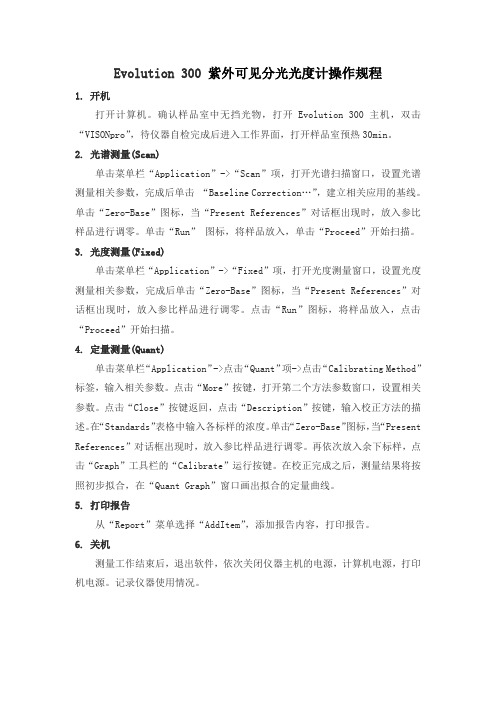
Evolution 300 紫外可见分光光度计操作规程1.开机打开计算机。
确认样品室中无挡光物,打开Evolution 300主机,双击“VISONpro”,待仪器自检完成后进入工作界面,打开样品室预热30min。
2. 光谱测量(Scan)单击菜单栏“Application”->“Scan”项,打开光谱扫描窗口,设置光谱测量相关参数,完成后单击“Baseline Correction…”,建立相关应用的基线。
单击“Zero-Base”图标,当“Present References”对话框出现时,放入参比样品进行调零。
单击“Run”图标,将样品放入,单击“Proceed”开始扫描。
3. 光度测量(Fixed)单击菜单栏“Application”->“Fixed”项,打开光度测量窗口,设置光度测量相关参数,完成后单击“Zero-Base”图标,当“Present References”对话框出现时,放入参比样品进行调零。
点击“Run”图标,将样品放入,点击“Proceed”开始扫描。
4. 定量测量(Quant)单击菜单栏“Application”->点击“Quant”项->点击“Calibrating Method”标签,输入相关参数。
点击“More”按键,打开第二个方法参数窗口,设置相关参数。
点击“Close”按键返回,点击“Description”按键,输入校正方法的描述。
在“Standards”表格中输入各标样的浓度。
单击“Zero-Base”图标,当“Present References”对话框出现时,放入参比样品进行调零。
再依次放入余下标样,点击“Graph”工具栏的“Calibrate”运行按键。
在校正完成之后,测量结果将按照初步拟合,在“Quant Graph”窗口画出拟合的定量曲线。
5. 打印报告从“Report”菜单选择“AddItem”,添加报告内容,打印报告。
常见紫外光谱仪器

常见紫外光谱仪器
常见的紫外光谱仪器有以下几种:
- 紫外-可见-近红外分光光度计(UV-Vis-NIR),可在紫外、可见和近红外光谱范围内进行光谱扫描,并对物质的吸光度或透光度进行测量,从而实现定性和定量分析。
- 紫外-可见分光光度计(UV-Vis),用于紫外光区和可见光区的光谱测量,可用于物质的定性和定量分析。
- 紫外光谱仪(UV),用于紫外光区的光谱测量,可用于物质的定性和定量分析。
- 紫外荧光光谱仪(UF),用于紫外光激发下物质的荧光光谱测量,可用于物质的定性和定量分析。
- 紫外拉曼光谱仪(UV-Raman),用于紫外光激发下物质的拉曼光谱测量,可用于物质的定性和定量分析。
- 紫外吸收光谱仪(UVA),用于紫外光区的光谱测量,可用于物质的定性和定量分析。
这些仪器的具体应用场景和功能会有所不同,你可以根据实际需要选择合适的仪器。
STI500液相色谱仪UV501紫外检测器说明书
赛智科技(杭州)有限公司
2 符号说明
符号 说明 适用于可能造成轻微人身伤害或造成仪器损坏的场合 帮助理解,提高操作效率的场合 特指键盘左方向键 特制键盘右方向键
ቤተ መጻሕፍቲ ባይዱ
参考 第一次使用该设备前,应通读本手册。
3 安装须知
3.1 安装的环境要求
提示
为了更好的使用 STI UV 501 检测器, 使其充分发挥高性能和长时间的操作稳定性, 请 检查安装场所是否满足下属要求: a. 通风 由于高效液相色谱仪所使用的容积易挥发引燃而且具有毒性,所以建议安装场所应具 备通风设施。 b. 火灾 不要在高效液相色谱仪安装的场所使用明火。同样,也禁止使用容易点打火的设备。 通常,应在那里备有灭火器,以防火灾的发生。 c. 水盆 应在仪器附近安装有水盆。一旦溶剂溅入眼睛或接触到皮肤,应立即用清水冲洗。 d. 腐蚀性气体或灰尘 高效液相色谱仪应避免暴露在腐蚀性气体和灰尘之中。 e. 电磁干扰 应避免将仪器安装于强电磁场中。如果市电中有波动,应使用附加的电源噪声滤波器。 f. 空间需求 仪器应安装在水平稳定的工作台上。台面的深度至少应有 100cm。 g. 其他要求 为了最后的发挥该检测器的性能,安装场所应满足如下的要求:
STI UV 501
®
可变波长紫外/可见分光检测器
安 装 使 用 手 册
Copyright © 2007, 2015. 版权所有 赛智科技(杭州)有限公司
赛智科技(杭州)有限公司
Science Technology CO.,Ltd Tel: +86-0571-28021919
目
1
录
2 3
4
5 6 7 8
综述...........................................................................................................................................2 1.1 概述...............................................................................................................................2 1.2 仪器特点.......................................................................................................................2 1.3 STI UV 501 可变波长紫外/可见分光检测器基本原理 .............................................3 符号说明...................................................................................................................................4 安装须知...................................................................................................................................4 3.1 安装的环境要求................................................................................................................4 3.2 拆箱....................................................................................................................................5 3.3 STI UV 501 标准装箱单 .................................................................................................5 操作...........................................................................................................................................5 4.1 通电...............................................................................................................................5 4.2 键盘操作及显示屏 .......................................................................................................7 4.3 菜单...............................................................................................................................8 4.3.1 主菜单(波长、量程) .....................................................................................9 4.3.2 灯源选择菜单 .....................................................................................................9 4.3.3 时间常数菜单 ...................................................................................................10 4.3.4 灯运行时间和光强度菜单 ............................................................................... 11 4.3.5 GLP 信息菜单 .................................................................................................. 11 故障维修.................................................................................................................................12 将 STI UV 501 接入 HPLC 系统 ............................................................................................14 STI UV 501 由软件控制 ........................................................................................................14 技术参数.................................................................................................................................14
三用紫外分析仪操作指导书
三用紫外分析仪操作指导书
(ISO9001-2015)
一、技术参数
1.1 灯管工作电压:50±10V
1.2 工作电流:1.70±10mA
1.3 灯管寿命:500小时左右
1.4 滤光片:254 nm 透光率≥20﹪ 365 nm 透光率≥30﹪
1.5 工作条件:温度0—40°C,相对湿度<95﹪
二、操作前准备
2.1 接上电源
2.2 准备检品
2.3 准备好黑绒布
三、操作过程
3.1将检品放在灯下,附上黑绒布。
3.2 选择所需波长对应的开关
3.3 按动开关
3.4 记录观察现象
3.5 检测结束后,关闭开关,拔下电源插头,盖上护罩。
3.6 填写使用记录
四、维修保养
4.1 将本仪器置于稳固台面上,避免受震动
4.2 避免用手直接接触灯管和滤光片。
4.3 滤光片应经常清洁,清洁方法用纱布沾上酒精和乙醚擦拭
4.4 将被检测物资置于灯下观察分析,切勿在灯开后,自下而上直接观看4.5 透过紫外滤光片工作时,应戴上平光镜保护眼睛。
4.6 检测结束后,关闭开关,切断电源。
西藏地面太阳总辐射与紫外线的观测

西藏地面太阳总辐射与紫外线的观测诺桑;晋亚铭;措加旺姆;周毅;索朗白姆;拉瓜登顿【摘要】地面太阳光谱记录了太阳光经历大气层的烙印与信息,为大气环境、生态保护等研究提供实地依据.西藏高原空气稀薄,地面太阳辐射超强,观测西藏地面太阳光谱为太阳能利用提供实地数据.文章较系统地报道了西藏地面太阳光谱的实地观测结果,为相关高原科学研究提供高精度数据.利用RAMSES光谱仪、CMP6太阳总辐射仪和NILU-UV太阳紫外辐射仪对西藏不同地区、不同季节太阳光谱、太阳总辐射和太阳紫外线进行了全方位的实地观测研究.观测研究了高海拔的西藏拉萨和那曲以及低海拔的北京和成都的光谱特征;研究了拉萨二分二至当地正午(北京时间13:55时)太阳光谱观测结果;对西藏地面光谱与AM1.5和AM0标准光谱进行了对比研究.观测研究了西藏拉萨和那曲太阳总辐射、太阳紫外线强度特征.研究发现拉萨夏季可见和红外区光谱光强度甚至超过AM0光谱相应波长的强度,即:拉萨地面可见光和红外光强度偶尔超过大气层顶部的相应波长光强,是由部分云的反射增量所致;拉萨光谱谱峰出现在波长476.6 nm左右,在2017年的夏至观测到的最大值为2.331 W·m-2·nm-1.然而,对太阳紫外线(280~400 nm)光谱的观测发现地面太阳紫外区的光谱强度总是明显低于AM0光谱相应区光强,表明短波的紫外光被大气臭氧有效吸收.虽然拉萨海拔3680 m,但通过对拉萨当地正午太阳紫外光谱分析发现拉萨地面波长小于300 nm的太阳紫外光谱强度几乎为零,表明波长小于300 nm的太阳紫外线被大气层吸收,没有到达地面.同时,研究了西藏高海拔太阳光谱与北京、成都低海拔太阳光谱特征,揭示了各地大气成分、含量等诸多信息.报道了2010年7月—2013年12月期间西藏太阳总辐射的观测结果;结果显示拉萨当日太阳总辐射最大值中约18%超过了太阳常数(1367 W·m-2).观测发现拉萨太阳总辐射瞬时最大值达到了1756.09 W·m-2(2011年6月24日).报道了2008年7月—2013年12月期间西藏太阳紫外线的观测结果;结果显示拉萨和那曲UVA日最大值平均值约为67 W·m-2,UVB日最大值平均值约为5.1 W·m-2;拉萨和那曲当日太阳紫外线A和紫外线B最大值变化趋势保持了很好的一致性,在5年多的观测期间紫外线强度没有出现明显的增强或减弱趋势.【期刊名称】《光谱学与光谱分析》【年(卷),期】2019(039)006【总页数】6页(P1683-1688)【关键词】西藏;太阳光谱;太阳总辐射;太阳紫外辐射【作者】诺桑;晋亚铭;措加旺姆;周毅;索朗白姆;拉瓜登顿【作者单位】西藏大学太阳紫外线实验室,西藏拉萨 850000;西藏大学太阳紫外线实验室,西藏拉萨 850000;西藏大学太阳紫外线实验室,西藏拉萨 850000;西藏大学太阳紫外线实验室,西藏拉萨 850000;西藏大学太阳紫外线实验室,西藏拉萨850000;西藏大学太阳紫外线实验室,西藏拉萨 850000【正文语种】中文【中图分类】P182.3引言西藏高原作为全球太阳辐射高值区[1],近年来对其太阳能利用和大气环境的研究倍受国内外的关注。
浙江诺锐光学仪器有限公司 UV VIS 光谱仪定性试验手册说明书

Each ampoule contains sufficient liquid for rinsing (conditioning) the cell twice and subsequently filling it. To condition a cell, half-fill it with solution, invert it so that the inside is completely wetted and empty completely. Repeat the procedure. Do not attempt to dry the inside of the cell. For measurement fill it immediately after conditioning. Prior to measurement, wipe the outside of the cell with a disposable paper tissue moistened in ethanol (for the purpose, please use residue-free absolute ethanol of spectroscopic quality, e.g. Uvasol®, Cat. No. 1.00980). Never touch the optical windows of the cell.
Steo 1: Baseline correction:
A baseline correction is not necessary for this Qualification.
Step 2: Measurement of the standard:
Spectrex 40 40UFI 超快速三光谱火焰检测器说明书

Headquarters: 8200 Market Boulevard | Chanhassen | MN 55317 | USATel: +1 (973) 239-8398 | +1 (800) 452-2107 (US only) | Fax: +1 (973) 239-7614 | Houston: +1 (832) 321-5229E-mail:*********************|FEATURES & BENEFITS 40/40UFI Ultra Fast Triple IR (IR3) Flame Detector Superior performance, reliability and immunity to false alarmsThe new 40/40UFI, an Ultra-Fast multi-spectrum IR3 Flame Detector, detectshydrocarbon fuel and gas fires at longdistances, and is especially designed todetect an explosive 1 ft (0.3m) diametergas cloud explosion in max. 50 msecs for1ft diameter sphere methane-air mixtureexplosion at 66 ft (20m) with the highestimmunity to false alarms. The 40/40UFIIR3 can also detect a 1 ft 2 (0.1m 2) gasoline/n-Heptane pan fire at up to 300 ft (90m).The 40/40UFI is part of the 40/40 Series,the most durable and weather resistantrange of flame detectors currently on themarket. Features include a heated window,to eliminate condensation and icing; HARTcapability for digital communications;lower power requirements; and a compact,lighter design. Due to increased reliability,the 40/40 Series warranty period has beenextended to 5 years and is SIL2 (TUV)approved per IEC 61508.Offshore Oil & Gas installations Onshore Oil & Gas installations and pipelines Chemical plants Petrochemicals plants Storage Tank farmsAircraft hangars • Multi Spectrum Design - for long distance detection and high false alarm immunity• High Speed Response - 50 msec • Sensitivity Selection - to ensure no zone crossover detection• Automatic Built-In-Test (BIT) - to assure continued reliableoperation• Heated window - for operation in harsh weather conditions(snow, ice, condensation)• Multiple output options for maximum flexibility andcompatibility- Relays (3) for Alarm, Fault and Auxiliary- Analogue output for fast detection- 0-20mA (stepped)- HART Protocol for maintenance and asset management- RS-485, Modbus Compatible• High Reliability - MTBF - minimum 150,000 hours• Safety Integrity Level SIL2 (TUV)• 5-Year Warranty • User Programmable via HART or RS-485• Hazardous area zones: - Zones 1 & 2 with IIC gas group vapors present - Zones 21 & 22 with IIIC dust type present • Ex approved to: - ATEX & IECEx - FM/FMC/CSA - TR CU (EAC)• 3rd party Performance - EN54-10 (VdS) - FM3260 (FM)Power Generation facilities Pharmaceutical Industry Printing Industry Warehouses Automotive Industry Explosives & MunitionsWaste Disposal facilities40/40R 40/40U-UB 40/40L4-L4B 40/40UFL 40/40L-LB 40/40I 40/40M 40/40UFISpectral Response Three IR Bands Detection Range Fuel ft / m Fuel ft / m Fuel ft / m (at highest Sensitivity Setting n-Heptane 300 / 90 Kerosene 205 / 62 Methane* 205 / 62for 1ft 2 (0.1m 2Gasoline 300 / 90 Ethanol 95% 185 / 55 LPG* 205 / 62High Speed Response 50 msec for 1ft diameter sphere methane-air mixture explosion at 66ft (20m)Response Time Typically 2 sec at 131ft (40m) Typically 10 sec at 300ft (90m)Adjustable Time Delay Up to 30 seconds Field of View Horizontal 90º; Vertical 90º Built-in-Test (BIT) Automatic Temperature RangeOperating: -67ºF to +167ºF (-55ºC to +75ºC)Option: -67ºF to +185ºF (-55ºC to +85ºC)Storage: -67ºF to +185ºF (-55ºC to +85ºC)Humidity Up to 95% non-condensing (withstands up to 100% RH for short periods) Heated OpticsTo eliminate condensation and icing on the window Operating Voltage 24 VDC nominal (18-32 VDC)Power ConsumptionStandby: Max. 90mA (110mA with heated window)Alarm: Max. 130mA (160mA with heated window)Cable Entries 2 x 3/4" - 14NPT conduits or 2 x M25 x 1.5 mm ISO Wiring 12 - 22AWG (0.3mm 2 - 2.5mm 2)Electrical Input Protection According to MIL-STD-1275B Electromagnetic Compatibility EMI/RFI protected to EN61326-3 and EN61000-6-3SPST volt-free contacts rated 2A at 30 VDC Analogue Output 4.75 - 5.25 V at detectionBIT Fault: 2mA ± 10% Alarm: 20mA ± 5%Normal: 4mA ± 10% Resistance Loop: 100-600 ΩHART Protocol Optional HART communications on the 0-20mA analog current (FSK) - used for maintenance, Dimensions Detector 4" x 4.6" x 6.18" (101.6 x 117 x 157 mm)WeightDetector (St.St.) 6.1 lb (2.8 kg) Tilt mount 2.2 lb (1.0 kg) Detector, aluminum 2.8 lb (1.3 kg)Environmental Standards Meets MIL-STD-810C for Humidity, Salt & Fog, Vibration, Mechanical Shock, High Temp, Low Temp Water and Dust IP66 and IP67 per EN60529, NEMA 250 6PPerformance EN54-10 (VdS) FM3260Reliability IEC61508 - SIL2 (TUV)Tilt Mount 40/40-001 789260-1 (3” pole) *777263 (Plastic)Duct Mount 777670 USB RS485 Harness Kit 794079 *Supplied free of charge with the detectorFor more information view manual or website Ex db eb op is IIC T4 Gb Ex db eb op is IIC T4 Gb Ex tb op is IIIC T96°C Db Ex tb op is IIIC T106°C Db (-55°C ≤ Ta ≤ +75°C) (-55°C ≤ Ta ≤ +85°C)FM/FMC/CSA Class I Div. 1, Groups B, C & D Class II/III Div. 1, Groups E, F & G TR CU (EAC) 1 Ex db eb op is IIC T4 Gb X Ex tb op is IIIC T96°C Db X (–55°C ≤ Ta ≤ +75°C) 1 Ex db eb op is IIC T4 Gb X Ex tb op is IIIC T106°C Db X (–55°C ≤ Ta ≤ +85°C) 1 Ex db eb mb op is II T4 Gb X Ex tb op is IIIC T98°C Db X (–55°C ≤ Ta ≤ +75°C)。
三用紫外分析仪标准操作方法
三用紫外分析仪标准操作方法
1.目的:
建立三用紫外仪的标准操作程序。
2.范围:
本规程适用于本公司三用紫外分析仪操作使用。
3.型号:
ZF7C型三用紫外分析仪
4.产地:
上海慧鑫科学仪器有限公司
5.程序:
5.1 接通电源。
5.2 点样:
5.2.1 将薄层板置载物台上,打开点样开关,点样点指示灯亮。
5.2.2 按点样操作方法,点样。
5.2.3 操作完成后,关闭点样灯。
5.3 显色:
5.3.1 将薄层板置载物台上;
5.3.2 打开紫外光灯,选择相应的波长;
5.3.3 照薄层色谱法检查法操作;
5.3.4 操作完成后依次关闭紫外灯、电源;
5.4 取下电源插头。
5.5 记录仪器使用记录。
6.仪器清洁与保养
6.1 使用前后应检查仪器状态是否良好;
6.2 用抹布清洁仪器表面,使清洁;
6.3 将仪器台面清洁干净,保持环境干净。
意大利3s总有机碳toc在线分析仪器原理
意大利3s总有机碳toc在线监测仪器原理和特点
来源:北京华信博润科技公司(意大利3stoc在线检测仪中国总代理)总有机碳toc分析仪器是采用紫外光谱法;含有共轭双键或多环芳烃的有机物溶解在水中时,对紫外光有吸收作用。
因此,通过测量这些有机物对254nm紫外光的吸收程度,以特别吸光系数SAC254来表达测量结果,作为衡量水中有机污染物总量的物理量。
根据比尔朗伯定律,测量原理是基于254nm波长的不饱和有机分子的紫外光吸收。
[C] = k log (Iin/Iout),[C]:试样浓度;K:紫外线吸收和TOC线性相关系数。
I in:入射光强,I out:透射光强。
总有机碳toc分析仪器的产品特点有哪些呢?北京华信博润科技为你讲解下:它是通过双光束系统(另一检测器550nm),实现对浊度、悬浮物以及脏物的自动补偿。
完全可编程序的分析循环,取样,条件反射,排水和清洗。
它测量时间非常快,自带浊度自动补偿功能。
自带自动校准/验证与可编程频率。
紫外光谱测量原理不需要化学试剂就会产生非常容易的操作和较低的维护成本。
自动清洗系统:一个全自动的清洗系统可以防止测量流量单元变得不干净,让分析者在不需要维护的情况下连续几周自动控制。
内置的数据记录仪使用USB来下载储存,内置蠕动泵。
长期的自主权,低维护,低运营成本。
可编程分析频率(从1到240分钟)。
适合检测:河水地表水,工业废水,化工厂,污水处理厂还有饮用水都是我们检测的对象。
比表面仪TriStarⅡ3020操作指导

比表面仪TriStarⅡ3020操作指导 研发部
认识比表面仪
脱气站
分析站
认识比表面仪
杜瓦瓶
样品管
设备操作
➢ 准备工作 ➢ 开机 ➢ 样品准备 ➢ 安装样品管 ➢ 建立样品文件 ➢ 开始分析 ➢ 关机
准备工作
1.检查气瓶压力值0.1-0.15MPa 2.确保杜瓦瓶内有足够液氮
开机
1. 开外围设备,包括:气体,泵,电脑等 2. 开主机电源 3. 打开应用软件
建立样品文件
样品信息栏从上 到下依次填入样 品名称,操作者, 送样人,样品质 量,样品密度 , 数据类型
样品名称 样品质量 数据类型
注释
操作者 送样人
脱气后, 样品管加 上样品的 质量
空样品管质量
建立样品文件
点击样品管 (Sample Tube),选择合适 的样品管信 息),根据实际 需要,选择是 否使用保温夹 和填充棒
结果报告
等温线性图
结果报告
相关系数
在bet列表报告中,其中判断数据是否有效主要判断C值和相关 系数,其中C值要大于0,相关系数越接近1越好
结果报告
孔容 孔径
对于类似硅铝的介孔材料,除了测试比表面还有测试孔容和孔径
UV-VIS光谱传感器产品说明书

ApplicationThe sensor measures the spectral absorption of process liquids in the ultraviolet region of the electromagnetic spectrum.•Measurement of protein concentrations •Chromatography monitoring •Filtration monitoring •Concentration measurement of organic compounds •Detection of aromatesYour benefits•Improved process control and easier quality control thanks to quick and reliable monitoring of product concentration –Measuring range up to 2.5 AU or 50 OD (depending on optical path length)–Measurement of UV absorption at discrete wavelengths between 254 nm and 365 nm –Outstanding filter properties for highest linearity –Direct concurrence with laboratory values –Integrated reference detector for lamp compensation –Gas discharge lamp for long service life and stable measured values •Patented Easycal system (optional)–Cost-effective, time-efficient calibration –Easy, in-line calibration which is traceable to NIST without any liquid standards •FM- and ATEX-approved lamps for applications in the hazardous area •Compliance with life sciences sector thanks to hygienic design and FDA- and USP-compliant sealing materials •High degree of product safety as SIP/CIP-resistant •High product yield thanks to low volume requirements •Maximum durability in all applications owing to wide range of materials and process connections •Can be adapted to process requirements:–Optional air purge ports to prevent the formation of condensate on the optical windows –Optional adjuster for optical path lengthProducts Solutions ServicesTechnical Information OUSAF44Optical sensor combined with the OUA260 flow assembly for the measurement of UV absorptionTI00416C/07/EN/13.1671316935OUSAF442Endress+HauserFunction and system designMeasuring principle Light absorption The measuring principle is based on the Lambert-Beer law.There is a linear dependency between the absorption of light and the concentration of the absorbing substance:A = -logA m = ε . c . OPLA ... absorption, A m ... absorption measured by detector ε ... Extinction coefficient c ... Concentration OPL ... Optical path lengthA light source emits radiation through the medium and the incident radiation is measured on the detector side.Once the light has passed through a filter for wavelength selection, the intensity of the light is determined by a photodiode and converted to a photocurrent.The subsequent conversion to transmission (%) or absorbance units (AU, OD) is performed in the associated transmitter.1Absorption measurement with reference 1Light source 2Optical windows 3Measurement filter 4Measuring detector 5Lens 6Medium flow 7Reference filter 8Reference detectorMeasuring system An optical measuring system comprises:•Sensor (photometer) OUSAF44•Liquiline CM44P transmitter •Cable set CUK80•Assembly to suit the sensor, e.g. OUA260OUSAF44Endress+Hauser 31pipe 5Flow assembly OUA2602Transmitter CM44P 6Sensor: light source (lamp)3Cable set CUK807Cable set CUK804Sensor: detector InputMeasured variableUV absorption Measuring range •0 to 2.5 AU •Max. 50 OD (depending on the optical path length)WavelengthDiscrete wavelength at 254, 280, 295, 302, 313 or 365 nmMore available on request Power supplyElectrical connection The sensor is connected to the transmitter using the pre-terminated or labeled cable set CUK80 (for connection to CM44P) or OUK40 (for connection to CVM40). The terminals and labeling may vary depending on the transmitter in use. The cable set must be ordered separately.OUSAF444Endress+Hauser3OUSAF44 connecting cable ALight source (lamp) power supply B Signals of measurement and reference detectorCable lengthMaximum 100 m (330 ft)Versions for use in hazardous areas Safety instructions for electrical apparatus in explosion-hazardous areas, XA01403CConnecting the detector using a safety barrierThe photometer sensors use silicon photovoltaic cells as detectors which are operated in the current mode. The detectors are intrinsically safe and can be deployed in Zone 1 environments.The safe area is separated from the hazardous area by one safety barrier MTL7760AC.OUSAF44Endress+Hauser 5The safety barrier may only have a very low leak current since the optical signals from the sensor can be in the nanoampere range. Therefore, the sensor cable shield is connected to the ground terminal of the barrier.On delivery, the CUK80 detector cable is permanently wired to the safety barrier. All you have to do is simply connect the individual cable ends to the detector and transmitter.Connecting the hazardous area lamp using a junction boxThe hazardous area lamp (EXP-1) must be connected to the transmitter using a certified junction box.For versions with FM approval, the junction box is included in the delivery and already pre-terminated on the lamp side. You simply have to connect the cable of the transmitter (CUK80)to the terminals of the junction box.For versions with ATEX approval, the junction box is not included in the delivery and it and the cable glands required must be provided by the customer at the place of installation. You must connect the cables entirely on your own (CUK80 of transmitter and lamp cable of photometer sensor).OUSAF446Endress+Hauser5Connecting the hazardous area lamp to CM44P using a junction boxInstallationInstallation instructions6Mounting angles. The arrows indicate the direction of medium flow in the pipe.APreferred mounting angle BOptimum mounting angle CAcceptable mounting angle DMounting angle to be avoided E Forbidden mounting angleOUSAF44Endress+Hauser 7EnvironmentAmbient temperature range 0 to 55 °C (32 to 130 °F)Storage temperature -10 to +70 °C (+10 to +160 °F)Humidity 5 to 95 %Degree of protection IP 65 (NEMA 4) for all optical partsProcessProcess temperature 0 to 90 °C (32 to 194 °F) continuous Max. 130 °C (266 °F) for 2 hoursProcess pressure Max. 100 bar (1450 psi) absolute, depending on the material, pipe size and process connection of the flow assemblyMechanical construction7Sensor module ADimension of lamp, depends on lamp type, see table BDimension of detector, see table C Assembly, see Technical Information for assemblyThe total length of the sensor module is derived from the lengths of the lamp, the detector and the assembly.The dimensions of the OUA260 assembly are provided in Technical Information, TI00418C.‣When connecting the sensor cable, make sure you maintain an additional distance of 5 cm (2")on both the lamp side and the detector side of the sensor.OUSAF448Endress+HauserWeight SensorUV lamp0.58 kg (1.28 lbs)UV lamp with wire-braided cable (1.2 m (4 ft)) and junction box (sensor for hazardous area)3.2 kg (6.66 lbs)Easycal detector0.65 kg (1.43 lbs)Standard detector0.36 kg (0.794 lbs)OUA260 assemblyTC ¼"1.14 kg (2.51 lbs)TC 1"1.39 kg (3.07 lbs)TC 2"1.88 kg (4.15 lbs)TC 4" 3.38 kg (7.45 lbs)MaterialsSensor housingStainless steel 316OUA260 assembly Stainless steel 316, 316L or Kynar or customer-specific material Depends on version Cable connection ends Nickel-plated brassLight source Pre-set, low-pressure mercury lamp Lamp operating life: typically 3000 h, at least 1000 hDetector UV silicon detectors, hermetically sealed Filter Multilayer interference filter, designed for extreme UV conditionsCertificates and approvalsmark Declaration of ConformityThe product meets the requirements of the harmonized European standards. As such, it complies with the legal specifications of the EC directives. The manufacturer confirms successful testing of the product by affixing to it the mark.Ex approvals •ATEX II 2G Ex db IIC T5 Gb •FM Cl.1, Div. 1, Groups B, C, DFDA conformityAll non-metal parts in contact with medium, such as rubber and plastic parts, meet the requirements of FDA 21 CFR 177.2600. The plastic and elastomer parts of the sensor in contact with medium have passed the biological reactivity tests according to USP <87> and <88> Class VI.Ordering informationProduct page /ousaf44Product Configurator On the product page there is a "Configuration" button to the right of the product image.1.Click this button. The Configurator opens in a separate window.2.Select all the options to configure the device in line with your requirements.In this way, you receive a valid and complete order code for the device.OUSAF44Endress+Hauser 93.Export the order code as a PDF or Excel file. To do so, click the appropriate button on the rightabove the selection window.For many products you also have the option of downloading CAD or 2D drawings of the selected product version. To do so, click the "CAD" tab and select the desired file type using drop-down lists.Scope of delivery The scope of delivery consists of the following depending on the version ordered:•sensor •Detector and lamp module without flow assembly or •Detector and lamp module mounted on OUA260 flow assembly •Operating InstructionsIf the sensor is ordered with a transmitter, the complete measuring system is factory-calibrated and shipped as one package.If you have any questions, please contact your supplier or your local sales center.AccessoriesThe following are the most important accessories available at the time this documentation was issued. For accessories not listed here, please contact your service or sales office.Flow assembly OUA260•Flow assembly for hygienic sensors •For sensor installation in pipes •Materials: stainless steel 316, 316L or Kynar (other materials available on request)•Wide variety of process connections and path lengths available •Product Configurator on the product page: /oua260Technical Information TI00418CCable CUK80 cable set •Pre-terminated and labeled cables for connecting analog photometer sensors •Product Configurator on the product page: /cuk80CalibrationOUSAF44 EasyCal retrofit kit •Patented system traceable to NIST for the online calibration of UV absorption sensors •Order numbers:–254 nm: 71210149–280 nm: 71210150–295 nm: 71210156–302 nm: 71210153–313 nm: 71210151–365 nm: 71210152Reference rod Order number: 71108543。
仪器名称 JASCO)V-550 紫外分光光度仪 (.
仪器名称:(JASCO)V-550紫外分光光度仪简单操作规程一、光谱扫描1、打开计算机和主机电源,计算机进入Windows操作界面。
2、打开仪器电源,预热十分钟。
在[Spectra Manager]界面下双击[Spectrum Measurement],进入光谱扫描模式。
3、点[Measurement] - [Parameter...]设置参数,设置完参数后,点[OK],参数被传送到仪器。
4、执行[Measurement] - [Baseline...],出现[Baseline Correction]基线修正对话框。
首先确认样品仓是空的,然后点Measure出现[Baseline Measurement]对话框,点Start进行测量。
测量完毕后基线被自动存储,选中[Baseline Correction],扫描后的谱图被自动扣除掉基线。
4、将样品放到样品仓[S]一侧,参比溶剂放在[R]一侧,然后盖好仓盖,点Start开始扫描。
5、扫描结束后谱图被自动输出到[Spectra Analysis]程序中,您可以在该程序中进行峰查找、峰面积和峰高计算、Y轴单位变换等一系列操作。
二、定量分析6、用鼠标双击桌面上Spectra manager图标启动[Spectra Manager]软件,然后再双击[Quantitative Analysis],进入定量分析模式。
7、选择[File] – [New…],出现[Open Parameters]对话框。
点New图标新建一组试验参数;或者从[Parameters List :]中选择已保存的实验参数,然后点[OK]确认。
8、点New后出现[Quantitative Measurement – Parameters]对话框。
在[Peak :___nm]一项空白处输入待测物质的最大吸收波长;如需要对标准品进行多次测量取平均值,在[No.of Cycle:]一项中输入重复次数,仪器会自动对每个浓度点重复测量若干次取平均值。
(T6新世纪紫外可见分光光度计操作规程)

T6新世纪紫外可见分光光度计操作规程
一、开机自检:打开仪器主机电源,仪器开始初始化,约3分钟时间仪器初始化完成。
初始化完成后,仪器进入主菜单。
二、进入光度测量状态:按
三、进入测量界面:按
四、设置样品测量波长:按
自动调整波长。
五、进入设置参数:按▼键使光标移动到“试样设
定”,按
▼键使光标移动到“使用样池数”,按
六、设定使用样品池个数:按○
环选择需要使用的样品池数。
七、样品测量:按
量界面。
在1号样品池内放入空白溶液,2号样品池内放入待测样品。
关闭好样
品池盖后按
如需测量下一个样品,取出比色皿,更换为下一个测量的样品
数。
如果需要更换波长,直接按
如果每次使用的比色皿个数固定,下一次使用时可跳过第5、6步骤直接进入样品测量。
注意:更换波长后必须重新按
八、测量结束:测量完成后记录数据,退出程序或关闭仪器后测量数据将消失。
确保已从样品池中取出所有比色皿,清洗干净后以便下一次使用。
按
直接返回到仪器主菜单界面后再关闭仪器电源。
紫外光谱仪结构
紫外光谱仪的结构包括以下几个主要部分:
1. 光源:紫外光谱仪通常使用氘灯或钨灯作为光源。
氘灯主要发射200-400纳米范围内的紫外光,而钨灯主要发射可见光和近紫外光。
2. 光路系统:光路系统用于引导光线进入光谱仪并将其分离为不同的波长组成。
它包括准直器、单色器和检测器。
准直器用于聚焦光线,单色器用于选择特定波长的光,检测器用于测量光强度。
3. 单色器:单色器是紫外光谱仪中最关键的部分之一。
它通过使用光栅或光柱等光学元件,将光线分散成不同的波长,并选择特定的波长传递到检测器。
4. 检测器:检测器用于测量通过单色器选择的特定波长的光的强度。
常用的检测器包括光电二极管(photodiode)和光电倍增管(photomultiplier tube)。
5. 数据处理和显示系统:紫外光谱仪通常配备计算机和显示器,用于处理和显示光谱数据。
计算机可以进行数据处理、存储和分析,并将结果以图表或图像的形式显示出来。
总之,紫外光谱仪的结构可以简单地描述为包括光源、光路系统、单色器、检测器和数据处理和显示系统。
不同型号的紫外光谱仪可能会有一些细微的差异,但整体结构和功能类似。
分子光谱 紫外可见分光光度计 NicoIet Evolution 300 说明书

分 子 光 谱Nicolet Evolution 300紫外可见分光光度计2Nicolet Evolution 300—— 操作智能、功能强大、无可匹敌美国热电集团最新的紫外可见分光光度计,继承英国Unicam的精湛传统,发扬美国Nicolet的智能化特长NicoIet Evolution 300是在积累了英、美杰出生产商60年紫外可见分光光度计生产经验的基础上精心打造出的新一代产品。
可靠的技术、全新的平台将在竞争中立于不败之地。
NicoIet Evolution 300性能可靠,经得起时间的考验。
评估校验是该系统的一个独特部分。
汞笔和UV波长校正功能,加上新的21 CFRPart11软件工具,可以满足甚至高于很多条例的要求,符合各种应用需求,简单自然。
智能附件、自动识别、快速追溯等仅仅几项特点就使得Nicolet Evolution 300成为最好的紫外可见分光光度计之一: 操作智能,结果准确。
请赶快给您的实验室购置一台Evolution 300,您就会感受到它本身所具有的智能化操作和高性能特点。
●双光束设计提供卓越稳定性和低漂移●高分辨、可变带宽●质量一流的石英涂层光学元件提供高能量输出和高灵敏度●智能附件和自动样品码识别使用方便●本机控制和/或PC控制满足实验室多种需要●专门应用:生命科学、制药和QC实验室●满足药典21 CFR Part 11要求的工具和多级安全管理选项●评估、校验和校准有助于您满足全部规则条例3Nicolet Evolution 300采用铸铝光学底座,光学件直接固定的底座上,因而系统稳定性极高。
即使在很恶劣的环境下,光学元件表面的石英涂层及密封光学系统仍能防止能量衰减。
90%反射率的大镜子,单个Ebert 单色器使能量输出最大化。
全息光栅的杂散光性能极佳,可测量吸收值高达6A 的样品。
步进驱动的光栅确保了波长准确性和测量重复性。
微距驱动器在每个数据点停留,消除了传统设计带来的峰变形和波长漂移。
三羟甲基氨基甲烷紫外吸收

三羟甲基氨基甲烷紫外吸收
三羟甲基氨基甲烷,也称为Tris,是一种常用的化学试剂,广
泛用于生化实验和分子生物学研究中。
关于其紫外吸收特性,这主要取决于其分子结构中的官能团。
三羟甲基氨基甲烷(Tris)的分子式为C4H11NO3,其中含有
3个羟基和1个氨基。
在紫外光谱范围(200-400 nm)内,羟
基和氨基可以吸收较弱的紫外光。
Tris的紫外吸收主要集中在200-230 nm范围内。
该化合物在
此范围内吸收较强的紫外光,产生吸收峰。
在230 nm以上的
紫外光范围内,Tris的吸收逐渐减弱,直至不可检测。
需要注意的是,具体的紫外吸收特性还受到溶液浓度、pH值、溶剂和其他共存物质的影响。
因此,在使用Tris时,应根据
实验需求和条件来选择合适的测量波长和条件。
Biomate3s操作规程

Biomate3s操作规程Thermo Scientific BioMate 3S 紫外分光光度计操作规程 1 概述Thermo Scientific BioMate 3S 内置有多种生化分析方法涵盖RNA/DNA 浓度及单细胞培养分析方法;适用多种附件,如高准确温度控制装置、自动操作系统及光纤进样系统。
采用氙灯 (Xenon Lamp) 光源,涵盖190~1100nm 全波长范围,光学采用双光束,人性化的软件设计,操作简单,节省分析时间。
该仪器由光源光源光源、、5部分组成。
2 技术要求2.1光源:氙灯(Xenon Lamp)2.2波长范围:190nm ~1100nm2.3波长精度:±1.0 nm2.4光度值法:双光束2.5狭缝宽度: 1.8nm2.6光度值范围:-0.5 – 5.0 A3 操作步骤3.1开机3.1.1 开机前检查并清理样品室内的比色池、干燥剂等,盖好样品室盖子。
3.1.2先接通电源,打开主机电源开关(POWER )。
3.1.3仪器进入自检状态,等待自检结束后出现操作界面。
3.2操作界面3.2.1按面板上的 UTILITY 键,屏幕出现Utility 界面。
3.2.2 在Utility 界面进行:选择语言选择语言选择语言、、设定日期和时间设定日期和时间、、待机设置待机设置、、设置基线终止时间线终止时间、、设置屏幕对比度设置屏幕对比度等基本的仪器设置。
3.2.3在Utility 界面可以调用调用/删除/加密或解密加密或解密一个测试方法。
3.2.4按面板上的 TEST 键,屏幕出现Test Types 界面,依据被测量样品的要求选择:吸光度吸光度/透光率透光率、、浓度浓度、、高级Abs/%T/C 、标准曲线标准曲线、、吸光度比率吸光度比率、、动力学动力学、、扫描扫描、、Bio Test 等测量模式。
3.2.5 当要求的模式被选中后,屏幕上将出现相应的操作界面,按照该界面的要求输入如波长波长波长、、时间时间等相应的参数。
- 1、下载文档前请自行甄别文档内容的完整性,平台不提供额外的编辑、内容补充、找答案等附加服务。
- 2、"仅部分预览"的文档,不可在线预览部分如存在完整性等问题,可反馈申请退款(可完整预览的文档不适用该条件!)。
- 3、如文档侵犯您的权益,请联系客服反馈,我们会尽快为您处理(人工客服工作时间:9:00-18:30)。
ProPS-Kit with Flowthrough unit and panel
TriOS Optical Sensors - Werftweg 15 - D-26135 Oldenburg - Germany - www.trios.de
(*) typ. ranges and detection limits. Both are depending on water matrix and components
Order codes 13 0010 13 0020 13 0030 85 1000 85 1010 41 0011 41 0012 41 0020 20 6010 20 6020 ProPS-N-Kit ProPS-C-Kit ProPS-CN-Kit NO2-Pre-calibration ‘spectralchange’ Police-function other pre-calibrations (on request) TriBox II GSM-Modul TriBox II WiFi-Modul TriBox II 4x 4..20mA Modul ProPS-Flowthrough unit ProPS-PPS-Kit
NO3, CODeq/TOCeq
by spectral UV analysis
ProPS-Kits are cost-effective and innovative setups for the online measurement of nitrate and/or CODeq/TOCeq. The individual kits include everything required for the measurement: ProPS-UV sensor, TriBoxII controller, 10m sensor cable and 10m tube for aircleaning. All systems are delivered ready-to-measure, with an installed pre-calibration for the ordered parameters., which works in most applications. All kits offer an user add-on calibration to adjust the measurement values to the individual conditions (reference values) if required. The ProPS is measuring a hyperspectral UV absorption spectrum to derive the individual measurement values. Additional calibration functions are offered and can easily be installed at customers side - without the need to purchase new hardware. This keeps your investment save with future requirements.
3 2,5 2 1,5 CODeq / TOCeq 1 0,5 0 190 abnormal structure Nitrate Nitrite
absorption [AU]
210
230
250
270
290
310
330
350
wavelength [nm]
Let the ProPS-Kit watch for pollutions: The additional available ‘policefunction’ triggers alarms if spectral signatures changes unexpectedly. ProPS-Kit includes everything required to start measurement Parameter NO3 NO2 CODeq TOCeq 0..100 mg/l (*) 0..50 mg/l (*) 0..5,000 mg/l (*) 0.. 500 mg/l (*)
310
330
350
wavelength [nm]
TriOS Optical Sensors - Werftweg 15 - D-26135 Oldenburg - Germany - info@trios.de
ProPS-Kit
Absorption spectra of waste water with and without CODeq
Absorption spectra of waste water with and without CODeq
3 2,5 2 1,5 CODeq / TOCeq 1 0,5 0 190 SAK254 TSS Nitrate Nitrite
absorption [AU]
210
230
250
270
290
