Agilent8960操作指导手册
8960无线通讯测试仪操作指南
8960无线通讯测试仪操作指南第一部分:基本操作1.开机:将仪器的电源插头插入电源插座,然后按下电源开关,等待片刻,仪器即可启动。
2.连接设备:使用测试线缆将待测试的设备与仪器连接。
根据设备的不同,连接方法也有所不同,可以参考连接图纸来正确地连接设备。
3.设置通道:在仪器界面上选择所需的通道。
通常情况下,仪器提供多个通道,用于测试不同的频段和协议。
通过触摸屏或旋钮,选择对应的通道。
4.配置参数:根据需要,设置测试参数。
这包括频率、功率、调制方式等参数。
在仪器的菜单中选择对应的选项,并进行相应的设置。
5.运行测试:确认所需的参数已设置完毕后,点击“开始测试”按钮,仪器开始执行测试任务。
测试结果将会显示在屏幕上或通过连接的电脑进行显示。
第二部分:高级操作1.自动化测试:仪器支持自动化测试功能,能够实现对设备进行一系列的自动化测试。
用户可以预先设置测试序列,然后通过点击“自动测试”按钮,仪器将按照预定的序列自动执行测试,并记录测试结果。
2.数据分析:仪器还提供数据分析功能,能够对测试结果进行分析和处理。
用户可以在仪器界面上选择需要分析的数据,并通过提供的分析工具对数据进行处理和展示。
4.结果记录:仪器支持测试结果的记录和保存功能。
用户可以在仪器界面上选择保存结果的格式和位置,并通过点击“保存结果”按钮将测试结果保存下来。
第三部分:常见问题解答1.为什么仪器无法启动?2.如何选择正确的通道?3.如何设置正确的测试参数?4.如何分析和处理测试数据?答:仪器提供了数据分析工具,用户可以选择需要分析的数据,然后使用提供的分析工具进行处理和展示。
5.是否支持远程控制?答:是的,仪器支持远程控制功能。
用户可以通过连接电脑,使用相应的软件对仪器进行远程控制。
本文介绍了8960无线通讯测试仪的基本操作和高级功能。
希望通过这篇操作指南,读者能够更好地掌握这款仪器,并能够有效地进行无线通信设备的测试和调试工作。
安捷伦8960实用简易操作说明
安捷伦8960实用简易操作说明安捷仑8960综合测试仪是GSM和CDMA手机测试常见的测试仪器,现把在生产过程常用的设置和调试在此说明,以便大家需要时参考1.如何将自动测试转换到手动测试?答:按面板右上方LOCAL键,进入本地设置状态即可(注:自动测试是指当仪器连接了电脑所有测试过程由电脑软件控制;手动测试即人工手动直接对仪器进行选择设置和测试。
)2.如何查看8960仪器的当前GPIB地址?答:1.按SYSTEM CONFIG键,进入系统设置界面,即可看到GPIB 地址,如:GPIB Address:20 3. 如何知道8960仪器当前的测试类型CDMA还是GSM?如何转换?答:1.按SYSTEM CONFIG键,进入系统设置界面,即可看到,如:Application:GSM/GPRS Mobile Test目前产线常用的有两种,(1)G网手机,采用GSM/GPRS Mobile Test(2)C网手机,采用CDMA2000 Mobile TestGSM手机校准时需把C网换成G网,否则不能校准,转换方法如下:先按按面板右上方LOCAL键,再Application Selection进入子画面,按Application Switch ,进入测试类型选项,通过旋钮选择GSM/GPRS Mobile Test或CDMA2000 Mobile Test,按下旋钮键确定,再选择YES 按下旋钮键确定,仪器将执行自动重启进入选定测试类项。
4.如何修改8960仪器的线损值?答:按SYSTEM CONFIG键,进入系统设置界面,按RF IN/OUT Amptd offset进入子画面,按IN/OUT Amptd offset setup,旋钮选择对应频段,按下旋钮键,进入线损值修改,如-10 dB。
(线损值理论上应该通过测试来定,但实际应用中直接输入经验值有8,10,12dB,使OK手机测试功率在33±3dB之内即可.5.如何用8960测试手机发射功率?答:在待机界面,按Mesutement Selection 进入弹出窗口,用旋钮选择功率***POWER 项,注意:GSM900M频段测试功率等级有5——15级, GSM1800M频段测试功率等级有0—15级,GSM900测试信道:1—124(中间信道62);GSM1800测试信道: 512—885(中间信道698),通话测试时:900M功率等级选最大5,信道选62,功率标准为33±3dB;1800M功率等级选最大0,信道选698,功率标准为33±3dB6.GSM手机接收灵敏度测试用手机建立一个呼叫连接,按下Measurement selection键(测试项目选择),选择测量项GSM Bit Error(误码),按下F7(BCH),再按F7调节Cell Power(信元功率),当Bit Error(误码)不超过2.4%时,Cell Power的值即为所测手机的接收灵敏度,国标为-102 dBm。
安捷伦8960_GSM主要射频指标测试手册
安捷伦8960简介
安捷伦8960是用于手机测试的综合测试仪, 在统一的硬件平台E5515A/B/C上可以根据 安装的软件不同进行各60界面说明
操作8960时主要是在三个屏幕里进行的,如 下图所示,在测试屏幕(MEASUREMENT)里进 行测试结果的读取和对测试参数的设置,在呼叫 设置屏幕(CALL SETUP)里进行呼叫建立的相关设 定,在系统配置(SYSTEM CONFIG)里配置仪器 地址等参数。 选择“MEASUREMENT”,“SYSTEM CONFIG”,“CALL SETUP”三个按键可以在这三个 测试界面里进行切换。
6. 按下F9键,把Traffic Channel选为1; 7. 按下F10键,把MS TX Level 选为第5功率等级; 8. 按下F12键,Return返回到CALL SETUP界面; 9. 按下F7键,进入BCH设置界面; 10.再次按下F7键,输入数据看GSM Fast Bit Error 的值是否是小于2.439%,选择一个最小的能够满 足条件的值,这个值就是所测手机在该信道的灵 敏度。 11.按下F12键Return返回,按下F8键进入TCH Parameters设置,按下F9键选择另外的信道进行 测试(GSM一般选择1,62,124这三个信道进行测 试就可)。
三. 功率测试设置
1. 点击8960右下方的“Measurement Selection”键 2. 在出现的选择菜单栏中选择GSM/GPRS Transmit Power 测试项,进入功率测试状态(旋转旋钮可以进行选择,按 下旋转按钮可以确认选择,也可以用Enter键进行确认)。 3. 按下F8键,进入TCH Parameters设置; 4. 再按下F8键, Traffic Band 选择为EGSM; 5. 按下F9键,选择测试信道—Traffic Channel (PGSM:1~124;EGSM:1~124,975~1023); 6. 按下F10键,选择功率等级为最大功率等级5(5~19); GSM一般测试1,62,124三个信道最大功率等级的功率 (33+/-2dbm)。
安捷伦综测仪E5515C 8960 使用手册 校准手册 Agilent 8960 E5515C
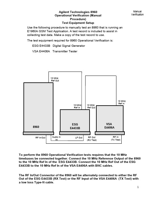
To perform the 8960 Operational Verification tests requires that the 10 MHztimebases be connected together. Connect the 10 MHz Reference Output of the 8960to the 10 MHz Ref In of the ESG E4433B. Connect the 10 MHz Ref Out of the ESG E4433B to the 10 MHz Ref In of the VSA E4406A with BNC cables.The RF In/Out Connector of the 8960 will be alternately connected to either the RF Out of the ESG E4433B (RX Test) or the RF Input of the VSA E4406A (TX Test) with a low loss Type-N cable.Agilent Technologies 8960Operational Verification (ManualProcedure)Test Equipment SetupUse the following procedure to manually test an 8960 that is running anE1960A GSM Test Application. A test record is included to assist incollecting test data. Make a copy of the test record to use.The test equipment required for 8960 Operational Verification is:ESG E4433B Digital Signal GeneratorVSA E4406A Transmitter Tester Manual Verification10 MHz Ref In10 MHzRef Out 10 MHzRef In 10 MHzRef OutRF In/OutESGE4433BVSA E4406A8960Audio InHi LF Out RF Out(RX Test)RF In (TX Test)Test Data Record for 8960 with E1960A GSM Test ApplicationFunctional Verification Expected Limit (Note 1)Pass Fail Analog Generator Level Accy ± 2.0 dBAnalog Generator Spectral PurityHarmonics ≤ -25 dBcSub-Harmonics ≤-40 dBcAnalog Audio Generator Accuracy ± 0.03VGSM GeneratorAmplitude Flatness ±.6 dBmPeak Phase Error (PGSM/EGSM) < ± 4 Deg(DCS/PCS) < ± 6 DegRMS Phase Error < ±2 Deg.Frequency Error (18 Hz) < ± .04 ppmAnalog Audio Analyzer Accuracy ± 0.04VAnalog Analyzer RF Power Meter ±1.6 dBmGSM Analyzer Frequency Measurement Accy. < ± 24 HzGSM Analyzer Residual Phase ErrorRMS Error < ±2 DegPeak Error < ± 8 DegGSM Analyzer PVT Accy Expected Limit (Note 1)Pass Fail PVT Offset 0usec and 542.8usec (0 dB) ± 2 dBPVT Offset -10usec ≤ 8 dBPVT Offset 552.8usec ≤ 8 dBGSM Analyzer ORFS Measurement Expected Limit (Note 1)Pass Fail ORFS Offset ± 100 kHz ≤-6 dBORFS Offset ± 200 kHz ≤ -33 dBORFS Offset ± 250 kHz ≤-38 dBORFS Offset ± 400 kHz≤ -67 dBORFS Offset ± 600 kHz ≤ -76 dBORFS Offset ± 800 kHz ≤-78 dBORFS Offset ± 1000 kHz ≤ -78 dBORFS Offset ± 1200 kHz ≤ -79 dBNote 1 - Expected test limit levels may vary according to test instrument source used. Expected limits listed may require modification.8960 Operational VerificationTest Record Manual Verification8960 Operational VerificationAnalog Generator Level Accuracy Analog Generator Level Accuracy is a test to insure that the 8960 can set a basic level and then step in 10 dB increments accurately.The expected limit is:RF Generator Output Level, RF In/Out (2 sources) - ± 2.0 dBThe current operating firmware in the 8960 does not allow manual operation ofamplitude or frequency using incremental steps for either Signal Generator 1 or 2; a PC with controlling software is required.Connect the 8960 RF In/Out Connector to the E4406A RF Input.On the 8960 press the ‘Local’ button and the ‘System Configure’ button .The GPIB address must be set to: 14Manual VerificationAnalog Generator Level Accuracy, cont.On the 8960 perform the following set up functions:1. Press the blue ‘SHIFT’ button and the ‘PRESET’button (frontpanel buttons not shown above).2. Press the display ‘Operating Mode’ button and set mode toTest using the knob.3. Press the display ‘Test Function’ button and set function toCW using the knob.4. Press the ‘RF Gen Freq’button and set frequency to 939 MHzusing the number keypad and the knob.5. Press the ‘RF Gen Power’button and set power to -10 dBmusing the number keypad and the knob.On the E4406A, press the ‘Preset’System button, the ‘MODE’Control button and set to ‘Basic’Mode .On the E4406A, press the ‘FREQUENCY’Control button and set the Center Frequency to 939 MHz.On the E4406A, press the ‘ZOOM’button, the ‘Marker’button, and the ‘Search’button. Select the ‘TRACE’screen button and set the trace to Spectrum Average.On the E4406A, press the ‘MEASURE’Control button.Step the 8960 down in amplitude in 10 dB increments to -80 dBm. Insure that each level step is accurate within ± 2 dB.On the 8960 perform the following set up functions:1. Press the ‘RF Gen Freq’button and set frequency to 1805.2 MHz.8960 Operational VerificationAnalog Generator Level Accuracy, cont.On the E4406A set Center Frequency to 1.8052 GHz. Step the 8960 down in amplitude in 10 dB increments to -80 dBm. Insure that each level step isaccurate within ± 2 dB.Manual Verification On the 8960 perform the following set up functions:1. Press the ‘RF Gen Freq’ button and set frequency to 1930.2 MHz .Analog Generator Level Accuracy, cont.On the E4406Aset Center Frequency to 1.9302 GHz. Step the 8960 down in amplitude in 10 dB increments to -80 dBm. Insure that each level step is accurate within ± 2 dB.Important Note:The 8960 contains 2 complete signal generator sources (these are very similar to the E4432/33B Signal Generator).The operating firmware of the 8960 only provides for operation of 1 source using the manual user interface (front panel) in the analog mode. It is not possible to test the second source in a analog mode using any manual method.However….the second source can be tested manually in a GSM transmit mode. See the test titled “GSM Generator Amplitude Flatness. Peak Phase Error, RMS Phase Error, and Frequency Error --- Source 2”in this section.Testing source 2 in an analog mode requires using the Verification Automated Software.Analog Generator Spectral PurityAnalog Generator Spectral Purity is a test to insure that the 8960 has harmonics and spurious signals within specification.The test is run by setting the 8960 to a carrier frequency of 300 MHz and power level of -10 dBm. Harmonics and spurious are checked at 450MHz, 600 MHz, 750 MHz, and 900 MHz. The expected limits are:Spectral Purity Harmonics - ≤ -25 dBcSub-Harmonics - ≤ -40 dBcNon-Harmonics - ≤ -55 dBc <1500 kHz≤ -68 dBc >1500 kHzThe current operating firmware in the 8960 does not allow manual operation of amplitude or frequency using incremental steps for either Signal Generator 1 or 2, a PC with controlling software is required.Connect the 8960 RF In/Out Connector to the E4406A RF Input.On the 8960 perform the following set up functions:1. Press the blue ‘SHIFT’ button and the ‘PRESET’button (front panel buttons notshown above).2. Press the display ‘Operating Mode’ button and set mode to Test using theknob. 3. Press the display ‘Test Function’ button and set function to CW using the knob. 4. Press the ‘RF Gen Freq’button and set frequency to 300 MHz using the number keypad and the knob.5. Press the ‘RF Gen Power’button and set power to -10 dBm using the number8960 Operational Verification Analog Generator Spectral PurityOn the E4406A, press the ‘Preset ’ System button, press the ‘Mode’ Control button and set to ‘Basic’ Mode.ManualVerification ON the E4406A make the following settings: Center Freq: 300 MHz Span: 10kHzPress the ‘ZOOM’ button, the ‘Marker’ button, and the ‘Search’ button. Select the ‘TRACE’ screen button and set the trace to Spectrum Average. The 8960On the E4406A set the center frequency to 450 MHz. Press the‘AMPLITUDE’button and set Ref Value to -50 dBm. The Sub-Harmonic expected limit is: ≤ -50 dBm.On the E4406A set Center Frequency to 600 MHz. The Harmonic expected limit is: ≤ -35 dBmOn the E4406A set the Center Frequency to 750 MHz. The Sub-Harmonic expected limit is: ≤ -50 dBmOn the E4406A set the Center Frequency to 900 MHz. The Harmonic expected limit is: ≤ -35 dBm .The Audio Generator test checks to insure that the 8960 has an audio sourcesignal with reasonable performance of accuracy.The test is run by setting the 8960 in the audio generator mode and looping anaudio signal from the Audio Out BNC connector to the Audio In Hi BNCconnector to measure level accuracy of the audio output. The audio generatorexpected limits are:Level Accuracy - ± 0.03VConnect the 8960 Audio Out Connector to the Audio In Hi Connector with a BNC cable.8960 Operational VerificationAudio Generator AccuracyBegin the test procedure by pressing the blue ‘SHIFT ’ button and RESET.ManualVerificationPress the Instrument Select button. Press the knob and activate theAudio Generator screen8960 Operational VerificationAudio Generator Accuracy,cont.Set audio amplitude to 1.414 V. Set audio frequency to 1 kHz.ManualVerificationThe Analog Audio measurement screen should appear. The8960 Operational VerificationAudio Generator Accuracy,cont.Manual VerificationPress the ‘Measurement Selection’ button. Use the knob and selectAnalog Audio, push the knob to start selection.8960 Operational Verification GSM Generator Amplitude Flatness, Peak Phase Error,RMS Phase Error, and Frequency ErrorSource 1GSM Generator tests check to insure that the 8960 has a GSM Digital signal within a reasonable specification.The test is run by setting the 8960 to a traffic channel of 30 and power level of -10 dBm. The E4406A is then set in a digital measurement mode and checks the 8960 GSM signal for Amplitude Flatness (PVT), Peak Phase Error, RMS Phase Error, and Frequency Error. The expected limits are:Amplitude Flatness - < ± .6 dBmPeak Phase Error - < ± 8 degrees in PGSM & EGSM Bands< ± 12 degrees in DCS and PCS BandsRMS Phase Error - < ± 2 degree in PGSM and EGSM BandsFrequency Error - < ± .04 ppm + TBManualVerificationOn the 8960 perform the following set up functions: 1. Press the blue ‘SHIFT’ button and the ‘PRESET’ button (front panel buttons not shown above).2. Press the display ‘Operating Mode’ button and set mode to Test using the knob.3. Press the display ‘Test Function’ button and set function to BCH + TCH using the knob.4. Press the ‘Broadcast Chan’ button and set the channel to 1 using the number keypad and the knob.Go to Screen 2 of 3. Set the Traffic Channel to 124 .8960 Operational VerificationGSM Generator Amplitude Flatness, Peak Phase Error,RMS Phase Error, and Frequency Error, Source 1 cont.ManualVerificationOn the E4406A set the Center Frequency to 959.8 MHz (channel 124). The Burst RF Spectrum should appear.On the E4406A, press the ‘MODE’Control button and set Mode field to GSM.On the E4406A, press the ‘AMPLITUDE’ Control button. Set ‘Scale/Div’ field to be .3 dB and the ‘Ref Value’ field to be -9 dBm. The display shown above should appear. The expected PVT limits are: <± .6 dB flatnessOn the E4406A, press the PVTbutton.8960 Operational VerificationGSM Generator Amplitude Flatness, Peak Phase Error,RMS Phase Error, and Frequency Error, Source 1 cont.On the E4406A, press the ‘Phase & Freq’ button. The display shown above should appear. The expected limits for Phase & Frequency are: Peak Phase Error - <± 4 Degrees in PGSM & EGSM Bands<± 6 Degrees in DCS and PCS BandsRMS Phase Error - <± 2 Degrees in PGSM & EGSM BandsFrequency Error - <± .04 ppm (18 Hz)ManualVerification8960 Operational VerificationGSM Generator Amplitude Flatness, Peak Phase Error,RMS Phase Error, and Frequency ErrorSource 2GSM Generator tests check to insure that the 8960 has a GSM Digital signal within a reasonable specification.The test is run by setting the 8960 to a traffic channel of 30 and power level of -10 dBm. The E4406A is then set in a digital measurement mode and checks the 8960 GSM signal for Amplitude Flatness (PVT), Peak Phase Error, RMS Phase Error, and Frequency Error. The expected limits are:Amplitude Flatness - < ± .6 dBmPeak Phase Error - < ± 8 degrees in PGSM & EGSM Bands< ± 12 degrees in DCS and PCS BandsRMS Phase Error - < ± 2 degree in PGSM and EGSM BandsFrequency Error - < ± .04 ppm + TBManual VerificationOn the 8960 perform the following set up functions:1. Press the blue ‘SHIFT’ button and the ‘PRESET’ button (front panel buttons not shown above).2. Press the display ‘Operating Mode’ button and set mode to Test using the knob.3. Press the display ‘Test Function’ button and set function to BCH+TCH using the knob.4. Press the ‘ Cell Power’ button and set power to -10 dBm using the number keypad and the knob.5. Press the ‘Cell Band’ button and set the cell band type to DCS using the knob.6. Press the ‘Broadcast Chan’ button and set the channel to 512 using the numberkeypad and the knob.Go to Screen 2 of 3. Set the Traffic Band to PGSM and the Traffic Channel to 124.Go to Screen 3 of 3. Set the expected burst to TSC0.On the E4406A set the Center Frequency to 959.8 MHz (channel 124). The Burst RF Spectrum should appear.On the E4406A, press the ‘MODE’ Control button and set Mode field to GSM.On the E4406A, press the ‘AMPLITUDE’ Control button. Set ‘Scale/Div’ field to be .3 dB and the ‘Ref Value’ field to be -9 dBm. The display shown above should appear. The expected PVT limits are: <± .6 dB flatnessOn the E4406A, press the PVTbutton.On the E4406A, press the ‘Phase & Freq’ button. The display shown above should appear. The expected limits for Phase & Frequency are:Peak Phase Error - <± 4 Degrees in PGSM & EGSM Bands<± 6 Degrees in DCS and PCS BandsRMS Phase Error - <± 2 Degrees in PGSM & EGSM BandsFrequency Error - <± .04 ppm (18 Hz)Begin the test procedure by pressing the blue ‘SHIFT ’button and RESET.8960 Operational Verification Analog Audio AnalyzerThe Analog Audio Analyzer is tested to insure that the 8960 can accurately measure an audio signal within a reasonable limit.The test is run by setting the 8960 into the Audio Analyzer measurementmode. The E4433B is then set to output an Audio signal on the LF Out connector at 1.414 Vp at a frequency of 1 kHz. The Analog Audio Measurement Accuracy expected limit is:Levels 10mv to 20V Peak - ± 0.04VFrequency 200 Hz to 8 kHzConnect a BNC cable between the E4433B LF Out connector and the 8960 Audio In Hi connector.Manual VerificationPress the ‘Measurement Selection’button. Use the knob and select Analog Audio, push the knob to start selection.The 8960 Analog Audio screen should display a voltage level measurement of the audio signal from the E4433B .The Analog Audio measurement expected limit is ± 0.04V8960 Operational VerificationAnalog Audio Analyzer, cont.Manual VerificationThe Analog Analyzer RF Power Meter is tested to insure that the 8960 can accurately measure an RF signal within a reasonable limit.The test is run by setting the 8960 into a manual measurement mode. The E4433B is then set to output a CW RF signal at various levels andfrequencies. The Analog RF Power Meter Accuracy expected limits are: Levels ≥ -20 to +43 dBM - < ± 1.60 dBFrequency 810 to 960 MHz8960 Operational Verification Analog Analyzer RF Power MeterManual VerificationBegin by connecting a cable between the RF Out port of the E4433B and the RF In/Out port of the 8960.939.000 000 0013.00FREQUENCY AMPLITUDE dBmEXT REF MHz RF ON ONMODSet the E4433B to output a signal at a frequency of 939 MHz,amplitude +13 dBm8960 Operational Verification Analog Analyzer RF Power Meter, cont.Manual VerificationOn the 8960 perform the following set up functions:1. Press the blue ‘SHIFT’ button and the ‘PRESET’button (front panel buttons notshown above).2. Press the display ‘Operating Mode’ button and set mode to Test using theknob.3. Press the display ‘Test Function’ button and set function to CW using the knob.Press ‘Measurement Selection’button and select ‘Transmit Power’asPress ‘Transmit Power Setup’button and set Trigger Source to ‘Immediate’.On screen 2 of 2 set Expected Power to +13.00 dBm. RF Power measurement Specification is < ± 1.63 dB.8960 Operational VerificationGSM Analyzer The GSM Analyzer is tested to insure that the 8960 can accurately measure a GSM burst signal within a reasonable limit.The test is run by setting the 8960 into GSM Analyzer manual measurementmode. The ESG E4433B is then set to output a GSM burst signal at +15 dBmamplitude. The GSM Analyzer Measurement Accuracy expected limits are:Frequency ErrorMeasurement Accy. - < ± 24 Hz + Time BaseResidual Phase ErrorMeasurement Accy RMS - < ± 2 DegreeMeasurement Accy. Peak - < ± 8 DegreesPower versus TimeRel. Measurement Accy at Time Offset - ± 2 dBORFSRel. Measurement Accy Freq. Offset - ± 3 dBBegin by connecting a cable between the RF Out port of the E4433B and the RF In/Out port of the8960. Set the E4433B to output a signal at a frequency of 939MHz, GSM On, Burst On or Framed Data, and amplitude +13 dBmManual Verification939.000 000 0013.00FREQUENCY AMPLITUDE dBm EXT REF MHz GSM ENVLP I /Q RF ON ON MOD GSMOff OnFramedData FormatPattern Configure TimeslotsData(N/A)Frame RepeatSingle ContFrame Trigger (N/A)More(1 of 2)GSM On Data Format: Framed Mod Type: MSK GSM: STANDARD Nxt Frame: Primary Data: PN23Repeat: Cont0Pol: NormalDiff Encode: On GSM Timeslot Pattern 12345670Bits/Symbol: 1SymRate: 270.8333ksps Filter: 0.300 Gaussian Chan: P-GSMBase 1I/Q Scaling: 100%CustomCustom Custom Custom Custom Custom Custom Off Off Off Off Off Off OffOn NormalGSM AnalyzerOn the 8960 perform the following set up functions:1. Press the blue ‘SHIFT’ button and the ‘PRESET’button (front panel buttons notshown above).2. Press the display ‘Operating Mode’ button and set mode to Test using theknob.Select screen 3 of 3. Set ‘Receiver Control’field to Manual. Set ‘Manual Freq’Press ‘Measurement Selection’button and select ‘Transmit Power’asthe Operating Mode. Transmit Power window should display a readingof approximately +13 dBmPress ‘Measurement Selection’button and select ‘Phase & Frequency Error’as the Operating Mode. Press ‘Phase & Frequency Setup’button. Select Multi-Measurement Count value to be 10. Close Menu to turn off the Setup window.The Phase and Frequency Error window should appear and displayaverage readings of Peak and RMSPphase error and Frequency error.The expected measurement limits are:Peak error is <± 8 Deg, RMS error is <±2 Deg, Frequency error is <±24 Hz.Press ‘Measurement Selection’button and select ‘Power vs. Time’as the Operating Mode. Press the ‘Power vs. Time Setup’button and then the‘Measurement Setup’button, set the Multi-Measurement Count value to be 10.Press ‘Return to PvT Control’button then press the ‘Change View’button.Press the ‘Numeric 1 of 2’button. The Power vs Time Numeric Screen 1 should appear. The expected limits are:0usec - 0dBc ±2dBc -10 usec - ≤ 8dBc8960 OperationalVerification GSM Analyzer, cont.Manual VerificationPress the ‘Numeric 2 of 2’button. The Power vs Time Numeric Screen 2 should appear. The expected limits are: 542.8usec - 0dBc ±2dBc 552.8usec - ≤ 8 dBc Note on measured values: Power versus Time measurements are depend on the accuracy of the source being measured. In the example above the E4433B had performance of -14 dBc at a 552.8 usec offset on the burst. Variation in burst timing can vary the offset in dBc greatly. This measurement is meant to show consistency between 8960 units using the same identical source for each unit tested.Press ‘Measurement Selection’button and select ‘Output RF Spectrum’as the Operating Mode. Press the ‘ORFS Setup’and then the ‘Measurement Setup’41Press ‘Return to ORFS Control’ button. Press ‘Change View’ button and select which modulation numeric screens to view by pressing either the ‘Modulation Numeric 1 of 3’ or the ’Modulation Numeric 2 of 3’ buttons..8960 Operational VerificationGSM Analyzer, cont.The ORFS measurement screen must be configured for offset frequency values to make a measurement. Press the ‘Modulation Frequencies’ button. Load the default frequencies into each offset by rotating the knob to each offset andpressing the ‘ON’ button. Load frequencies 100 kHz to 1200 kHz. Close the menu.Manual Verification42The expected ORFS measurement limits are: (example)ORFS Offsets ± 100 kHz - ≤ -6 dBORFS Offsets ± 200 kHz - ≤ -33 dBORFS Offsets ± 250 kHz - ≤ -38 dBORFS Offsets ± 400 kHz - ≤ -67 dBORFS Offsets ± 600 kHz - ≤ -76 dBORFS Offsets ± 800 kHz - ≤ -78 dBORFS Offsets ± 1000 kHz - ≤ -78 dBORFS Offsets ± 1200 kHz - ≤ -79 dBORFS Offsets > 1200 kHz - ≤ -80 dBNote: A measured value (example: -79 dB at 600 kHz) is dependent on theperformance of the source being measured. In this example a typical E4433B may have ORFS performance of -79 dB at 600 kHz from the carrier. The values may change however according to the source. The measured accuracy of a source should be consistent for every 8960 unit. The measurement done for this test ismeant to show test consistency between 8960 units using the same identical source for each unit tested.8960 Operational VerificationGSM Analyzer, cont.ManualVerification。
安捷伦8960综测仪操作指导
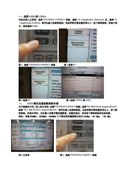
一,选择GSM或CDMA开机后进入主界面,选择“SYSTEM CONFIG”按钮,选择F3(Application Selection)后,选择F1(Application Switch),调节仪器上的旋转按钮,光标停留在需设置的项目上,按下旋转按钮,即选中项目,例如选择GSM。
图1. 选择“SYSTEM CONFIG”按钮图2.选择F3图3.选择F2 图4.选择CDMA或GSM一,GSM测试设置线路损耗补偿打开综测仪开关,进入到主界面,选择“SYSTEM CONFIG”按钮,选择“F5(RF IN/out Amptd offset)”,选择“F2(RF IN/OUT Amptd Offset)”,调节仪器上的旋转按钮,光标停留在需设置的项目上,按下旋转按钮,即选中项目,用仪器上的数字键设置数值,设置完成后,再次按下旋转按钮即完成设置。
例如:设置900MHz,1800MHz,1900MHz三个频点的传输损耗分别为-25dBm、-30 dBm、 -20 dBm图5.主界面图6. 选择“SYSTEM CONFIG”按钮图7. 选择F5按钮图8.选择F2按钮图9.旋转按钮图10.设置损耗值图11设置损耗值图12.按旋转按钮二,GSM连接设置按下仪器上“CALL SETUP”按键,然后按下按键“F 7(BCH)”,Cell power设为-60dBm,cell bard为EGSM(测试EGSM和DCS都可选择EGSM,测试PCS要选择PCS),按F12返回。
按下按键“F8(TCH)”,Traffic Band设为测试频带(EGSM,DCS,PCS),选择Traffic channel为所测试相关信道信号(EGSM为62,DCS为699,PCS为660)设置Ms Tx level(EGSM设为5,DCS,PCS 设为0)按F12返回图13.按“CALL SETUP”按键图14.连接设置三,GSM连接综测仪操作把终端放置到综测仪指定位置,打开终端TF测试卡内phone(GSM)软件,按下仪器上“CALL SETUP”按键,按左侧按键“F3 (Originate Call)”,综测仪向机器发出呼叫,仪器出现“Alerting”时,点击终端软件上“接听”选项,终端显示“已接听”,此时综测仪显示“Connected”,证明终端已经连接上综测仪。
安捷伦8960测量原理及操作说明
安捷伦8960测量原理及操作说明一、测量原理1.信号调制解调:测量设备与被测设备之间建立无线连接后,通过信号调制解调模块将测试信号转换成与被测设备相适应的信号,然后将被测设备发送的信号经过解调转换成数字信号。
2.信号发射与接收:通过射频信号处理系统,将数字信号转换成高频射频信号,通过无线天线发送到被测设备,同时接收被测设备发送的信号。
3.信号分析:通过信号处理单元,对接收信号进行频谱分析、波形分析、调制解调分析等,获取信号的各项参数。
二、操作说明1.连接设备:将测试设备与被测设备通过数据线或者无线连接,在软件界面上选择正确的接口和通信制式。
2.设置测试参数:根据测试需求,设置相应的测试参数。
包括频率范围、带宽、功率级别、调制方式等。
3.启动测试:点击开始测试按钮,仪器将自动产生测试信号并发送到被测设备。
同时,仪器将接收被测设备发送的信号并进行分析。
4.监测信号性能:根据测试需求,在界面上选择需要监测的信号性能参数,如信号强度、误码率、速率等。
仪器将实时显示和记录这些参数。
5.结果分析:测试完成后,可以通过仪器提供的分析工具对测试结果进行进一步分析,如绘制波形图、功率谱图、调制解调图等。
6. 测试报告生成:系统可生成详细的测试报告,包括测试参数、测试结果、分析图表等。
可以导出为Excel、PDF等格式。
三、使用注意事项1.使用正确的天线和连接器,确保信号传输的质量和稳定性。
2.在设备连接之间进行频谱清洁,避免干扰信号的出现。
3.在设置测试参数时,根据被测设备的要求进行合理选择。
4.在测试过程中要注意设备的工作温度和通风情况,确保设备的正常运行。
5.对于不同通信制式的测试,要熟悉相关的技术标准和测试规范,确保测试结果的准确性。
通过以上的操作说明,您可以正确使用安捷伦8960进行无线信号测试和性能检测。
根据测试需求,合理设置测试参数并分析测试结果,可以帮助您更好地了解被测设备的性能和信号质量。
安捷伦8960常用使用方法
安捷伦8960常用使用方法一、启动和连接1.将8960与电源适配器连接并接通电源。
2.使用USB线将8960与电脑连接。
3. 打开PC Application Manager(PCAM)。
在PCAM主界面,选择仪器配置,然后选择安捷伦通信仪器配置向导(Agilent Connection Expert)。
4.在配置向导中,点击“”按钮,选择8960无线通信测试仪。
5.配置仪器地址,点击“确定”完成配置。
二、创建和配置测试项目1.在PCAM中,选择“测试”选项卡,然后点击“创建测试项目”按钮。
2.在创建测试项目向导中,选择您要测试的技术类型(如LTE、WCDMA等)和版本。
点击“下一步”。
3.在配置测试项目向导中,根据测试需求选择适当的配置选项,如信道模型、功率控制设置等。
点击“下一步”。
4.配置测试项参数,如频率、功率、带宽等。
点击“下一步”。
5.配置高级设置,如硬件连接和接收测试。
点击“下一步”。
6.配置测试报告设置,选择报告生成方式和路径。
点击“下一步”。
7.点击“完成”按钮完成测试项目的创建和配置。
三、进行测试1.在PCAM中,选择“测试”选项卡,然后选择您创建的测试项目。
2.点击“开始测试”按钮开始测试过程。
3.在测试过程中,仪器将自动进行测试并记录测试结果。
4.在测试完成后,可以在PCAM中查看测试结果,包括各种指标和性能参数。
四、分析和优化1.在PCAM中,选择“分析”选项卡,然后选择您感兴趣的测试项目。
2.可以查看各种指标和性能参数的分析结果,如信号质量、功率控制、误码率等。
3.根据分析结果,可以进行优化和改进,如调整测试参数、改变信道模型等。
五、生成测试报告1.在PCAM中,选择“报告”选项卡,然后选择您感兴趣的测试项目。
2.点击“生成报告”按钮生成测试报告。
3.可以选择生成报告的格式和布局。
4.点击“生成”按钮生成测试报告。
六、其他功能和操作1.通过PCAM界面可以对仪器进行各种操作,如远程控制、固件升级等。
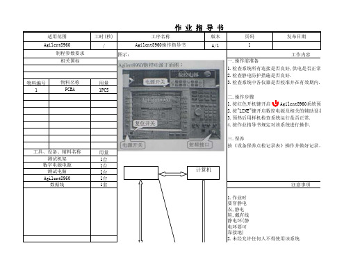
【制造行业必备表格类】Agilent8960操作指导书知名品牌公司推荐
工时(秒)
版本发布日期
/
A/1
图示:
物料编号
用量11PCS
用量1台1台1台1台1套
1.作业时要穿静电衣,静电鞋,戴有线静电环(静电环要可靠接地)
数据线
注意事项
2.未经允许任何人不得使用该系统.
数字电源电源测试电脑 Agilent8960
三.保养
按《设备保养点检记录表》操作并做好记录。
工具、设备、辅料名称
测试机架二.操作步骤
1.按红色开机键开启 Agilent8960系统预热
2.按"LINE"键开启数控电源及相关的辅助设备各
3.预热后用样机检查系统运行是否正常.
4.按作业指导书规定对该系统进行操作.2.检查静电防护措施是否良好.
物料名称 3.检查系统中各仪器是否校准并在有效期内.PCBA
制程参数要求工作内容
相关国标
一.操作前准备
1.检查系统所有连接是否良好,供电是否正常.
适用范围工序名称
页码Agilent8960
Agilent8960操作指导书
1
计算机
拟定:审核:核准:
算机操作系统.
闭排插的电源电关.可私自非法操作.。
Agilent 8960(WCDMA)操作说明

Agilent 8960(WCDMA)操作说明第1章基础知识1.1 WCDMA网络架构图1.2 WCDMA知识点第2章WCDMA的基本设置2.1 WCDMA的切换2.2 8960控制状态的切换2.3 8960软体的选择第3章8960测试前初始设置3.1 BCCH+ATT3.2 Speech Source3.3 Security Operation3.4 RLC3.5 UE Target Power 第4章常用测量项目及设置4.1 WCDMA的RX的测量方法及算法4.2 Maximum RF Output Power 4.3 Minimum RF Output Power 4.4 Occupied Bandwidth (OBW) 4.5 Spectrum Emission Mask 4.6 Adjacent Channel LeakagePower Ratio (ACLR)4.7 Frequency Error4.8 Error Vector Magnitude(EVM)4.9 Peak Code Domain Error1.1 WCDMA 网络架构图第三代行动通讯系统WCDMA 包含UE 、UTRAN (UMTS terrestrial radio access network,陆地无线接入网)、CN (Core Network )三大部分,其网络架构图如下:第1章基础知识1.2 WCDMA知识点(1) CDMA的容量是GSM的5倍(2) WCDMA的Level范围为:0~~15 (GSM的Level范围为: 5~~19)No power level for WCDMA(3) WCDMA:TX Channel :9613—9887 频率:1920MHz—1980MHz RX Channel :10563—10837 频率:2110MHz—2170MHz WCDMA的Loss frequency 的范围是从1.8GHz到2.5GHz~(4) WCDMA的频率与信道的换算方法为:Frequency ×5=Channel(GSM无此关系)(5) 3频手机是GSM900/1800/1900 3个频段.第2章WCDMA的基本设置2.1 WCDMA的切换2.2 8960控制状态的切换2.3 8960软体的选择第3章8960测试前初始设置3.1 BCCH+ATT3.2 Speech Source3.3 Security Operation3.4 RLC3.5 UE Target Power(第4章常用测量项目及设置4.1 WCDMA的RX的测量方法及算法RSSI=(RSCP-115.5)-(ECNO/2-24.25)4.2 Maximum RF Output Power 初始设置:Measurement Selection Thermal PowerMulti Measurement & Count Trigger Arm4.3 Minimum RF Output PowerMeasurement Selection Channel Power其他设置类似于前面的Thermal Power4.4 Occupied Bandwidth (OBW)Measurement Selection Occupied Bandwidth4.5 Spectrum Emission Mask Measurement Selection Spectrum Emission Mask4.6 Adjacent Channel Leakage Power Ratio (ACLR)Measurement Selection (ACLR)量测到的实际界面(左图)8960测量到的值ETSI 的SPEC 值(可自行修改)4.7 Frequency ErrorMeasurement Selection Frequency Error4.8 Error Vector Magnitude (EVM) Measurement Selection Waveform Quality这次测量后,把前面的UE Target Power 由24dBm改为-20dBm再测量一次就可以了4.9 Peak Code Domain Error Measurement Selection Waveform QualityThe END thanks!The END thanks!。
Agilent 8960C 8961C 无线通信测试仪 手动操作 入门指南说明书

(??FKDSWHUV?WLWOHSDJHIP
(??FKDSWHUV?WLWOHSDJHIP
安全符号 小心 请参见随附的文档 警告 触电危险 接地端子 交流电 机框或机架端子 待机 通电状态 设备带有此符号 表示开关关闭时 设备并未完全从交流电源 上断开
要彻底断开交流电源 可拔下电源线 也可以请合格的电工安装一个外置开关
保修期 年
安捷伦科技公司对本公司的硬件 附件和零部件在材料和工艺上的缺陷 在上述期限内予以保 修 在保修期内 安捷伦科技公司如果收到此类缺陷的通知 则将自行决定对经证实有缺陷的 产品进行维修或更换 更换的产品可能为全新或基本全新的产品
安捷伦科技公司保证在上述期限内 其软件如被正确安装和使用 则不会由于材料和工艺上的 缺陷 导致不能执行其编程指令 在保修期内 如果安捷伦科技公司收到此类缺陷的通知 则 将更换由于这种缺陷而不能执行编程功能的软件介质
接通电源前
确认将产品设置为与现有的线电压匹配 安装了合适的熔断器并采取了所有的安全措施 请留意安全符号下面所述的仪器外部标识
将仪器接地
为尽量减少触电危险 仪器机架和外罩必须与电气接地保护端连接 仪器必须通过一根接 地电源线与交流电源相连 并且地线与电源插座的电气连接端 安全接地 牢固连接 中 断任何接地保护导线或断开任何接地保护端子 都会导致引起人身伤害的潜在触电危险
安全信息概述
在本仪器工作的各个阶段都必须采取以下一般性安全措施 不采取这些安全措施或不遵从 本手册其他地方所述的特定警告 将会违反仪器设计 制造和使用的安全标准 安捷伦科 技公司对于客户违反这些要求所造成的后果不承担任何责任 总则 本产品为 类安全仪器 带接地保护端子 如果不按操作手册使用本产品 其保护功能 可能会削弱 根据 ,(& 本产品使用的发光二极管 /(' 均为 类产品 本产品依据 ,(& 3XEOLFDWLRQ 6DIHW\ 5HTXLUHPHQWV IRU (OHFWURQLF 0HDVXULQJ $SSDUDWXV ,(& 出版物 电子测量设备的安全性要求 设计并已通过测试 供货时状态良好 此说明性文档包含了用户必须遵守的安全事项和警告条件 以确保安全 操作以及在安全条件下维护此产品
Agilent 8960操作指导书
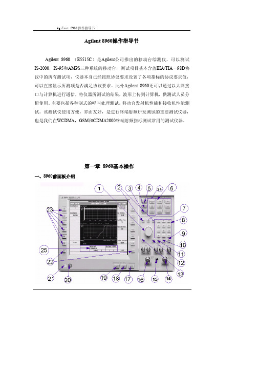
Agilent 8960操作指导书Agilent 8960 (E5515C)是Agilent公司推出的移动台综测仪,可以测试IS-2000,IS-95和AMPS三种系统的移动台,测试项目基本含盖EIA/TIA—98D协议中的所有测试项,仪器本身已经按照协议要求设置了各项指标的协议要求值,可以直接显示所测项是否满足协议要求。
此外Agilent 8960还可以通过以太网接口与计算机进行通信,将仪器所测试的结果,波形上传到计算机,供测试人员分析使用。
主要包括各种制式的呼叫处理测试,移动台发射机性能和接收机性能测试。
该测试仪使用方便,界面友好,是进行终端射频研发测试的重要测试仪器,也是我们在WCDMA,GSM和CDMA2000终端射频指标测试常用的测试仪器。
第一章8960基本操作一、8960前面板介绍1:方向与确认钮 11:自动设置键 21:电源开关2:方向键 12:删除键 22:选择下页键3:系统设置键 13:取消键 23:设置项选择键4:呼叫设置键 14:RF IN 24:状态栏5:测试启动键 15:网络接口 25:手机状态显示6:功能键 16:RF OUT7:增量设置 17:注册键8:数字与符号键 18:功能选择键9:回车键 19:测试项选择键10:手动选择键 20:复位键二、移动台测试仪Agilent8960测试连接组网三、移动台测试仪Agilent8960基本操作步骤1、给仪器接上电源,让仪器预热约30分钟;开机后界面:2、将移动台和该测试仪连接起来。
可以用直连电缆,也可以利用屏蔽盒(后者效果更好)将移动台和测试仪连接起来;3、模式设置:(包括IS-2000,IS-95,AMPS三种模式,本文以IS-2000模式为例)先按下CALL SETUP键,进入设置界面后,按下F1键选择Active cell操作模式,按下F2键选择IS-2000系统模式;4、测量参数设置:(主要设置的参数包括:Cell Power,Cell Band,Channel,Protocol Rev, Radio Config 及FCH Service Option Setup)按下F7键输入Cell Power的值,一般默认值为-55dbm/1.23MHZ;按下F8键选择Cell Band,800MHZ手机选择US-Cellular,450MHZ选择NMT-450;按下F9键选择Channel,输入手机要注册的频点,一般选择手机所在频点;按下F10键选择Protocol Rev,这里大部分手机选择6(IS-2000-0);按下F11键选择Radio Config的类型,按下F12键选择Service Option的类型;按下More键,可以对其他的参数进行设置,如SID,NID,闭环功率控制模式,业务/基本信道的数据速率,接收功率控制等,这里不作介绍。
安捷伦8960测量原理及操作说明
安捷伦8960测量原理及操作说明
安捷伦8960测量原理及操作说明
一、引言
本文档旨在详细介绍安捷伦8960测量仪器的原理及操作步骤,以帮助用户更好地理解和使用该设备。
二、设备概述
1、设备外观及主要组成部分
2、设备技术参数
3、设备功能及应用领域
三、测量原理
1、信号发生及调制原理
2、信号接收及解调原理
3、信号分析原理
四、设备使用前准备
1、设备安装及连接要求
2、设备电源接入
3、设备连接计算机或其他设备
五、设备操作步骤
1、设备开机及初始化
2、测试配置设置
3、测试场景选择
4、测试参数设置
5、数据记录与分析
6、测试报告
六、常见故障解决方法
1、设备无法开机
2、设备显示异常
3、测量结果不准确
七、常见操作技巧和注意事项
1、测试项选择建议
2、测试环境要求
3、定期维护保养
附件:
本文档附带以下附件供参考使用:
1、安捷伦8960设备说明书
2、测试案例示例文件
3、相关技术资料
法律名词及注释:
1、测试配置设置 - 指设备进行测试前的参数设置,以满足特
定测试需求。
2、测试场景选择 - 指根据不同测试目的选择合适的测试环境,如网络场景、信号强度等。
3、测试参数设置 - 指设备进行测试时需要用户设置的相关参数,如频率、功率等。
4、数据记录与分析 - 指设备自动记录测试数据并提供分析功能,以评估测试结果的准确性。
5、测试报告 - 指设备自动根据测试数据相应的报告,以便用
户查看和保存。
8960操作
EDGE和GPRS多时隙测试1 GPRS发射测试、EDGE多时隙发射测试1 手机装白卡链接Agilent 8960 并开机2 打开GPRS,3 在Agilent 8960 上的【Operating Mode】(即F1键)中设为Active Cell(GPRS)/Active Cell (EGPRS),并在【Date Conn Type】(即F2键)中设为ETSI Type A。
4 在Agilent 8960上按下【CALL SETUP】键,再按下【】8960测试前的设置1 按【SHIFT】键+【preset】键,初始化8960。
2 按【CALL SETUP】键,选择【Operating Mode】(即F1)键,将其设为Cell off。
3 按【More】键(屏幕左下方)移动到第2页(2 of 5)。
①先选择【Cell Parameter】(即F2)键,将【BCCH Update Page】设为Auto、【ATT(IMSIAttach)Flag State】设为Set,按【Close Menu】(即F6)键关闭菜单。
②再选择【Uplink Parameters】(即F4)键,将【Maximum Uplink Transmit Power Level】设置为24dBm(Power Class 3)或者21dBm(Power Class 4),其他功率等级请参考Table5.2.1,按【Close Menu】(即F6)键关闭菜单。
4 按【More】键(屏幕左下方),移动到第4页(4 of 5),然后按F1键进入【Security Info】,再按F1键进入【Security Parameters】将【Security Operations】设为【Auth & Int】(测试白卡为Agilent的白卡)或者None(其他厂商的白卡,如R&S)、【】Open Loop Power Control in the Uplink (上行开环功率控制)1确认手机已经进入连接状态。
安捷伦8960测量原理及操作说明
安捷伦8960测量原理及操作说明安捷伦8960测量原理及操作说明1.简介本文档旨在提供关于安捷伦8960测试仪的测量原理及操作说明。
安捷伦8960是一款常用于移动通信设备测试的测试仪器,具有多种功能和测量选项。
2.原理介绍2.1 通信原理在移动通信领域,安捷伦8960基于数字信号处理技术和射频技术,能够模拟基站信号,与待测设备进行通信。
通过不同的信号,可以对各种移动通信标准进行测试。
2.2 功能原理安捷伦8960测试仪内置了多种测试功能,如功率测量、频谱测量、调制解调、通信性能测试等。
这些功能的实现是通过仪器内部的算法和信号处理模块来完成的。
3.操作说明3.1 连接设备首先,确保将安捷伦8960正确连接到待测设备。
根据设备的接口类型和连接要求,选择适当的连接方式,并进行相应的物理连接。
3.2 仪器配置在开始测试之前,需要对安捷伦8960进行相应的配置。
首先,设置待测设备的通信标准和参数,以便能够正确地模拟通信环境。
然后,选择相应的测试功能和测量选项,根据需要进行配置。
3.3 开始测试配置完成后,开始按钮,安捷伦8960将开始向待测设备发送信号,并对其进行相应的测量和分析。
根据不同的测试目的,可以选择适当的测试模式和参数。
3.4 结果分析测试完成后,安捷伦8960会测试报告,并显示各项测试指标的结果。
根据需要,可以对测试结果进行进一步的分析和处理。
4.附件本文档附带以下附件:附件1:安捷伦8960使用手册附件2:安捷伦8960技术规格5.法律名词及注释为避免发生法律纠纷,本文档中涉及的法律名词及注释如下:1) 移动通信设备:指用于移动通信的各类终端设备,如方式、平板电脑等。
2) 测试仪器:用于对移动通信设备进行测试和测量的仪器设备。
3) 通信标准:移动通信设备遵循的技术规范和通信协议。
4) 功率测量:对设备输出的射频功率进行测量的过程。
5) 频谱测量:对设备输出的信号频谱进行测量和分析的过程。
6) 调制解调:对设备信号进行调制和解调的过程。
Agilent 8960操作指导书
Agilent 8960操作指导书Agilent 8960 (E5515C)是Agilent公司推出的移动台综测仪,可以测试IS-2000,IS-95和AMPS三种系统的移动台,测试项目基本含盖EIA/TIA—98D协议中的所有测试项,仪器本身已经按照协议要求设置了各项指标的协议要求值,可以直接显示所测项是否满足协议要求。
此外Agilent 8960还可以通过以太网接口与计算机进行通信,将仪器所测试的结果,波形上传到计算机,供测试人员分析使用。
主要包括各种制式的呼叫处理测试,移动台发射机性能和接收机性能测试。
该测试仪使用方便,界面友好,是进行终端射频研发测试的重要测试仪器,也是我们在WCDMA,GSM和CDMA2000终端射频指标测试常用的测试仪器。
第一章8960基本操作一、8960前面板介绍1:方向与确认钮 11:自动设置键 21:电源开关2:方向键 12:删除键 22:选择下页键3:系统设置键 13:取消键 23:设置项选择键4:呼叫设置键 14:RF IN 24:状态栏5:测试启动键 15:网络接口 25:手机状态显示6:功能键 16:RF OUT7:增量设置 17:注册键8:数字与符号键 18:功能选择键9:回车键 19:测试项选择键10:手动选择键 20:复位键二、移动台测试仪Agilent8960测试连接组网三、移动台测试仪Agilent8960基本操作步骤1、给仪器接上电源,让仪器预热约30分钟;开机后界面:2、将移动台和该测试仪连接起来。
可以用直连电缆,也可以利用屏蔽盒(后者效果更好)将移动台和测试仪连接起来;3、模式设置:(包括IS-2000,IS-95,AMPS三种模式,本文以IS-2000模式为例)先按下CALL SETUP键,进入设置界面后,按下F1键选择Active cell操作模式,按下F2键选择IS-2000系统模式;4、测量参数设置:(主要设置的参数包括:Cell Power,Cell Band,Channel,Protocol Rev, Radio Config 及FCH Service Option Setup)按下F7键输入Cell Power的值,一般默认值为-55dbm/1.23MHZ;按下F8键选择Cell Band,800MHZ手机选择US-Cellular,450MHZ选择NMT-450;按下F9键选择Channel,输入手机要注册的频点,一般选择手机所在频点;按下F10键选择Protocol Rev,这里大部分手机选择6(IS-2000-0);按下F11键选择Radio Config的类型,按下F12键选择Service Option的类型;按下More键,可以对其他的参数进行设置,如SID,NID,闭环功率控制模式,业务/基本信道的数据速率,接收功率控制等,这里不作介绍。
Agilent8960操作指导书

A g i l e n t8960操作指导书(总5页)-CAL-FENGHAI.-(YICAI)-Company One1-CAL-本页仅作为文档封面,使用请直接删除Agilent8960操作指导书1.目的规范测试员能熟练掌握仪器的使用操作步骤。
2.适用范围适用于公司各类产品的射频传导和天线耦合测试工作。
3.相关文件无4.所需设备、工具、材料Agilent-设备型号:8960-E5515C。
5.过程5.1.准备工作:1.检查电源是否正常通电。
2.是否能正常开机。
3.每天试验前根据《实验室仪器点检表》进行操作点检确认。
5.2.操作步骤:一、对于GSM/GPRS制式的手机,常需要测量的参数有:✓发射功率✓功率时间模板✓相位误差&频率误差✓开关谱&调制谱✓参考灵敏度电平1.打开电源开关,仪器面板如下图所示(见图一);2.线损设置:按SYSTEM CONFIG,弹出如下界面。
按RF IN/OUT Amptd Offset 。
按F5, RF IN/OUT Amptd Offset Setup。
输入要设置的频率及对应的线损,对于与处于Off状态的项目,我们按On键即可开启。
(详细步骤见8960原理及使用方法介绍)。
3.建立连接:按SYSTEM CONFIG,打开如下界面。
按 Format Switch,选择要切换的制式,在这里我们选择GSM/GPRS。
在Operating Mode里选择 Active Cell (GSM),按 Original Call,当屏幕下方显示Connected的时候,表示连接已成功。
在屏幕右侧Traffic Band中选择需要的频段,在Traffic Channel中选择需要的信道。
在手机与8960已连接的情况下,按Measurement selection,选择 Transmit Power,进入测试界面。
按确定可以看到测试结果(详细过程见8960原理及使用方法介绍)。
Agilent8960仪器操作指导书
Agilent8960仪器操作指导书1.目的规范测试员能熟练掌握仪器的使用操作步骤。
2.适用范围适用于公司各类产品的射频传导和天线耦合测试工作。
3.相关文件无4.所需设备、工具、材料Agilent-设备型号:8960-E5515C。
5.过程5.1.准备工作:1.检查电源是否正常通电。
2.是否能正常开机。
3.每天试验前根据《实验室仪器点检表》进行操作点检确认。
5.2.操作步骤:一、对于GSM/GPRS制式的手机,常需要测量的参数有:✓发射功率✓功率时间模板✓相位误差&频率误差✓开关谱&调制谱✓参考灵敏度电平1.打开电源开关,仪器面板如下图所示(见图一);2.线损设置:按SYSTEM CONFIG,弹出如下界面。
按RF IN/OUT Amptd Offset 。
按F5, RF IN/OUT Amptd Offset Setup。
输入要设置的频率及对应的线损,对于与处于Off状态的项目,我们按On键即可开启。
(详细步骤见8960原理及使用方法介绍)。
3.建立连接:按SYSTEM CONFIG,打开如下界面。
按Format Switch,选择要切换的制式,在这里我们选择GSM/GPRS。
在Operating Mode里选择Active Cell (GSM),按Original Call,当屏幕下方显示Connected的时候,表示连接已成功。
在屏幕右侧Traffic Band中选择需要的频段,在Traffic Channel中选择需要的信道。
在手机与8960已连接的情况下,按Measurement selection,选择Transmit Power,进入测试界面。
按确定可以看到测试结果(详细过程见8960原理及使用方法介绍)。
4. 发射功率:在手机与8960已连接的情况下,按Measurement selection,选择Transmit Power,进入测试界面。
按确定可以看到测试结果(详细过程见8960原理及使用方法介绍)。
8960个人使用指南
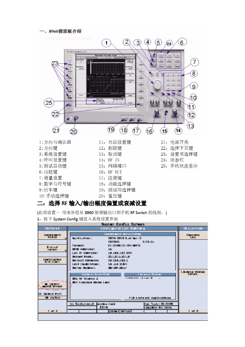
二:选择RF 输入/输出幅度偏置或衰减设置(此项设置一 用来补偿从8960射频输出口到手机RF Switch 的线损。
)1:按下System Config 键进入系统设置界面2:按下F5键选择RF IN/OUTAmptd Offset 进入界面:点击进入RF IN/OUT Amptd Offset Setup设置界面,选择RF IN/OUT Amptd OffsetState为On,在Frequency栏设置频点,在Offset栏设置对应的补偿值(可以输入20个频点)。
置好后,可以在屏上方看到设置的信息。
(一般情况下,只用两个,其他的全部OFF;传导测试的时候:《直接用射频线》GSM900的线损cable coss 可以设置为-0.5dB, DCS1800的线损设置为-0.8dB 偶合测试的时候:《用三角锥仪器》GSM900的线损cable coss 可以设置为-22dB, DCS1800的线损设置为-26dB)三:选择测试项目:按动显示屏右下面的Measurement Selection按钮,选择测试项目进行测试。
利用方向与确认扭,选中Digital Average Power(有时会有误码率的测试),点击进入界面:接通之前,记得将cell power 设置为-60Dbm,属于绝对射频频道号,建立呼叫!GSM 频段选1、62、124 三个频段,功率级别选最大LEVEL5;DCS 频段选512、698、885 三个频段,功率级别选最大LEVEL0 进行测试。
(1)测试传导\耦合功率(2)测试传导\耦合灵敏度(3)看PVT曲线图,误码率、在任何频率上,对正常和极限测试条件的每一种组合及每一种功率控制电平下,对常规突发的抽样测量其功率/时间关系(即功率包络)都应在图2 所示的阴影限制之内。
对接入突发的抽样测量其功率包络应在图3 所示的阴影限制之内。
(4):频率误差(Frequency Error)测试原理及方法:选择Agilent8960的Measurement Selection选项,设置为Phase/Frequency Error,选择Frequency Error,即可观测到频率误差值。
Agilent8960操作规范

2)按下Operating Mode (工作模式) (F1)鍵,並選擇Active Cell (活動信元)工作模式.
3)按下MORE(其他)鍵以選擇2頁螢幕的第2個螢幕.
4)按下F1. F2或F3,以更改可用的信元參數;數位控制通道使用SYSTEM ID. SOC和MCC.類比控制通道使用SYSTEM ID.
3)輸入用於您所用的測試頻率的幅度偏移量.
4)按下Close Menu (關閉菜單) (F6)鍵.
5)按下Return to Config Summary (返回配置概要) (F6)鍵.
5.8.3檢查消息日誌
1)按下Message Log (消息日誌) (F6)鍵,查看消息日誌.
2)按下Return to Utilities (返回實用程式)(F12)鍵.
3)選擇要切換到的通道類型(AVC或DTC).
4)更改用於AVC或DTC的各種參數.
5)按下Execute Handoff (執行切換)(F5)鍵完成切換,或按Close Menu (關閉功能表) (F6)鍵取消切換.
6)檢查Active Cell Status (活動信元狀態)域中是否顯示Connected (已連接).
7)注意當前業務通道資訊發生的變化.
5.8如何為測試系統配置測試儀
5.8.1配置儀器資訊及設置
1)按下SYSTEM CONFIG (系統配置)鍵.
2)按下Instrument Setup (儀器設置) (F1)鍵.
3)調整儀器設置,然後按下Close Menu (關閉功能表)(F6)鍵.
5.8.2設置幅度偏移量
6.3保養完畢應填寫《檢測儀器維護保養記錄表》.
安捷伦8960仪表操作指南

目 录第1章基础知识 (1)1.1 GSM测量频率频道范围 (1)1.2 频率频道换算 (1)1.3 复用方式 (1)1.4 移动台输出功率控制 (2)1.5 单位换算 (3)第2章 8960呼叫参数设置 (4)2.1 常用按键说明 (4)2.2 设置CABLE LOSS (4)2.3 GSM呼叫参数设置 (5)2.3.1 设置广播信道参数 (BCH PARAMETERS) (6)2.3.2 设置业务信道参数(TCH PARAMETERS) (6)2.4 GSM CONTROL设置 (9)2.4.1 设置OPERATING MODE (9)2.4.2 设置CONNECTION TYPE (9)2.4.3 ORIGINATE CALL (10)2.4.4 PAGING IMSI (12)2.4.5 HANDOVER SETUP (12)2.5 GPRS呼叫参数设置 (13)2.6 GPRS CONTROL设置 (16)2.6.1 设置GPRS OPERATING MODE (16)2.6.2 设置GPRS CONNECTION TYPE (17)2.6.3 START DATA CONNECTION (18)2.6.4 PAGING IMSI (20)2.6.5 HANDOVER SETUP (20)第3章 8960测量方法 (21)3.1 GSM的测量 (21)3.1.1 GSM TRANSMIT POWER 输出功率测量 (21)3.1.2 POWER VS TIME 功率时间测量 (23)3.1.3 PHASE & FREQUENCY ERROR (30)3.1.4 OUTPUT RF SPECTRUM (34)3.1.5 GSM BIT ERROR (40)3.2 GPRS的测量 (42)3.2.1 GPRS POWER VS TIME 功率时间测量 (42)3.2.2 GPRS BLOCK ERROR测量 (45)3.3 GSM/GPRS与WCDMA切换 (46)第1章基础知识1.1 GSM测量频率频道范围Channel:1-124 频率:890.2MHz—914.8MHz PGSM TX:1-124 频率:935.2MHz—959.8MHzChannelRXChannel:1-124 975-1023 频率:880.2MHz—889.8MHz EGSM TX:1-124 975-1023 频率:925.2MHz—934.8MHz ChannelRX:512-885 频率:1710.2MHz—1784.8MHz ChannelDCS TX:512-885 频率:1805.2MHz—1879.8MHz ChannelRXChannel:512-810 频率:1850.2MHz—1909.8MHz PCS TX:512-810 频率:1930.2MHz—1989.8MHz ChannelRX1.2 频率频道换算1.PGSM-900TX=Fl(n)=890+0.2*n (1<=n<=124) 62ch=902.4MHzRX=Fu(n)=Fl(n)+45 62ch=947.4MHz 2.EGSM-900TX=Fl(n)=890+0.2*n (1<=n<=124) 37ch=897.4MHz TX=Fl(n)=890+0.2*(n-1024) (975<=n<=1023)RX=Fu(n)=Fl(n)+45 37ch=942.4MHz3.DCS-1800TX=Fl(n)=1710.2+0.2*(n-512) (512<=n<=885) 698ch=1747.4MHzRX=Fu(n)=Fl(n)+95 698ch=1842.4MHz 4.PCS-1900TX=Fl(n)=1850.2+0.2*(n-512) (512<=n<=810) 661ch=1880MHz RX=Fu(n)=Fl(n)+80 661ch=1960MHz1.3 复用方式GSM使用TDMA(时分多址)和FDMA(频分多址)。
- 1、下载文档前请自行甄别文档内容的完整性,平台不提供额外的编辑、内容补充、找答案等附加服务。
- 2、"仅部分预览"的文档,不可在线预览部分如存在完整性等问题,可反馈申请退款(可完整预览的文档不适用该条件!)。
- 3、如文档侵犯您的权益,请联系客服反馈,我们会尽快为您处理(人工客服工作时间:9:00-18:30)。
A g i l e n t8960操作指导书
1.目的
规范测试员能熟练掌握仪器的使用操作步骤。
2.适用范围
适用于公司各类产品的射频传导和天线耦合测试工作。
3.相关文件
无
4.所需设备、工具、材料
Agilent-设备型号:
5.过程
);。
按F5, RF IN/OUT Amptd Offset Setup。
输入要设置的频率及对应的线损,对于与处于Off状态的项目,我们按On键即可开启。
(详细步骤见8960原理及使用方法介绍)。
3.建立连接:按SYSTEM CONFIG,打开如下界面。
按 Format Switch,选择要切换的制式,在这里我们选择GSM/GPRS。
在Operating Mode里选择 Active Cell (GSM),按 Original Call,当屏幕下方显示Connected的时候,表示连接已成功。
在屏幕右侧Traffic Band中选择需要的频段,在Traffic Channel中选择需要的信道。
在手机与8960已连接的情况下,按Measurement selection,选择 Transmit Power,进入测试界面。
按确定可以看到测试结果(详细过程见8960原
理及使用方法介绍)。
4. 发射功率:在手机与8960已连接的情况下,按Measurement selection,选择 Transmit
Power,进入测试界面。
按确定可以看到测试结果(详细过程见8960原理及使用方法介绍)。
5.功率时间模板:在已连接的情况下,按Measurement selection,选择Power vs Time。
确定之后显示如下界面。
按Change View,选择Graph,可以看到图示化的测试结果(详细过程见
8960原理及使用方法介绍)。
6.频率误差&相位误差:在已连接状态下,按Measurement selection,选择 Phase & Frequency Error。
按确定,可以看到测量结果。
按Change View,选择Graph,可以观察图示化的测量结果(详细过程见8960
7.开关谱&调制谱:在已连接的状态下,按Measurement 。
按确定可以看到测试结果。
按 Modulation Numeric和
原理及
按BCH Parameters,将Cell Power 更改为Bit Error Setup,将Loopback Delay -15dBm,观察FER。
对于DCS/PCS,
原理及使用方法介绍)。
&矢量幅度误差
✓灵敏度
✓最大输入电平
✓内环功率控制
✓开环功率控制
1.连接:按SYSTEM CONFIG ,在Format Switch 中选择WCDMA。
左侧翻到第二页,选择Cell Parameters, 将BCCH Update page 设为Auto。
将ATT (IMSI Attach) Flag State 改为Set。
按F4, 选择Uplink Parameters, Maximum Uplink Transmit Power Level设为24dBm。
左侧翻到第4
页,选择Security Info ,找到Security Parameters, 将Security Operations 设为None。
右侧,将Cell Power设为-50dBm。
按F12,Channel (UARFCN) Parameters,点DL Channel 设置所需的信道。
右侧第二页,将RLC Reestablish 更改为Off。
右侧翻到第3页,将UE Target Power 设为24dBm。
按Active Cell,激活信元,按Original Call进行呼叫(详细过程见8960原理及使用
方法介绍)。
2.最大发射功率:在连接状态下按Measurement selection, 选择Channel Power。
按确定,观察测试结果。
按Channel Power Setup,将Multi-Measurement Count设为10,可以看到最大,最小,平均值等。
(详细过程见8960原理及使用方法介绍)。
3.最小发射功率:将Cell Power 设为-93dBm设为
-55dBm,连接。
按Measurement selection,选择 Channel Power F1, Channel Power Setup,将Multi-Measurement Count 改为10
Mask。
按
Occupied Bandwidth。
按确定,
改为10,可以看到平均值,
-20dBm,连接。
按Measurement
Waveform Quality Setup,将
选择Waveform Quality。
改为10,可
原理及使用方法介绍)。
8.灵敏度:在手机连接状态按Measurement selection,选择 Loopback BER。
对于W2100,观察-106.7dBm时的比特误码率。
对于W850/W900/W1900,观察-104.7dBm时的比特误码率。
对于W2100,Cell Power从-106.7dBm开始往下走,(W850/W900/W1900从-104.7dBm) 但比特误码率不超过0.1%满足要求的最小值为灵敏度的测试值(详细过程见8960原理及使用方法介绍)。
9.最大输入电平:将Cell Power设为-25dBm。
将UE Target Power设为20dBm。
左侧第二页,按F3,Generator Info,选择F3, Downlink Channel Levels。
按F3, Connected DL Channel Levels。
按F2, WCDMA Conn DL Channel Levels。
将Connected DPCH Levels设为-19dBm。
按
Measurement selection, 选Loopback BER。
按F1, Bit Error Setup, 将Number of bits to test 更改为161040,观察测试结果(详细过程见8960原理及使用方法介绍)。
10.内环功率控制:在连接状态下按Measurement selection, 选择Inner Loop Power。
按Inner Loop Power Setup。
Test Segment选A,按START SIGNAL,则出现内功控A的测试结果。
Test Segment选B,按START SIGNAL,则出现内功控B的测试结果。
Test Segment选C,按START SIGNAL,则出现内功控C的测试结果。
Test Segment选E,按START SIGNAL,则出现内功控E的测试结果。
Test Segment选F,按START SIGNAL,则出现内功控F的测试结果。
Test Segment选G,按START SIGNAL,则出现内功控G的测试结果。
Test Segment选H,按START SIGNAL,则出现内功控H的测试结果(详细过程见8960
11.开环功率控制:左侧翻到第二页,按General Info,。
按F2,Initial DL Channel Levels,将CPICH Level设为-3.9dB,
设为
Off
(MMAX
将Primary CPICH TX Power设为28dBm, 。
在右侧第一页,将Cell Power 设为on/off Power。
点击F1(PRACH
设为:9.0dB,Open Loop Power Error 8960原理及使用方
制式下连接到8960的,必须要切换(F5,Handovers。
选择F3,Alerting State和Wait for RLC
里选择要切换到的频段。
Execute
8960原
理及使用方法介绍)。
三、通过本指导书的学习,大家应该掌握:手动测试和软件的设置方法。
WCDMA/EDGE/GPRS/GSM/CDMA的测试方法:
✓WCDMA/EDGE/GPRS/GSM/CDMA的常用测试项目;
✓测试上述项目的基本方法;
四、测试完成后取出试验品,关闭电源整里桌椅,请不要遗留实验室以外的任何物品。
6.保养注意事项
1.此设备必须培训后上岗操作。
2.设备出现故障时,需立即切断电源,并通知厂家维修。
3.仪器周围和地面要随时保持清洁,以免灰尘吸入机组内部而产生意外事故和降低性能。
7.表单/记录
7.1《实验室仪器点检表》
7.2《8960原理及使用方法介绍》。