GT21型真空继电器 15kV GTVAC
CM-MSS.51S 温度保护电机保护继电器说明书
Overvoltage Category Pollution Degree Short-Circuit Protective Devices Electrical Durability Mechanical Durability Connecting Capacity
Long Description
Ordering
EAN Minimum Order Quantity Customs Tariff Number
Dimensions
CM-MSS.51S 1SVR730712R1300
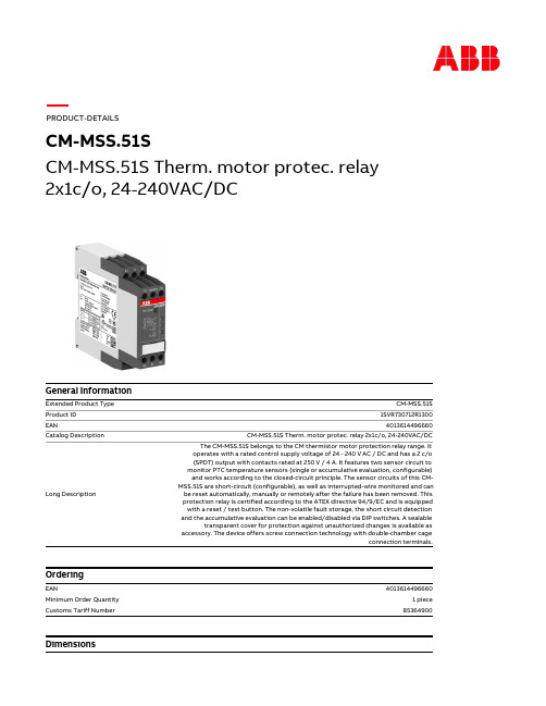
4013614496660 CM-MSS.51S Therm. motor protec. relay 2x1c/o, 24-240VAC/DC The CM-MSS.51S belongs to the CM thermistor motor protection relay range. It operates with a rated control supply voltage of 24 - 240 V AC / DC and has a 2 c/o (SPDT) output with contacts rated at 250 V / 4 A. It features two sensor circuit to monitor PTC temperature sensors (single or accumulative evaluation, configurable) and works according to the closed-circuit principle. The sensor circuits of this CMMSS.51S are short-circuit (configurable), as well as interrupted-wire monitored and can be reset automatically, manually or remotely after the failure has been removed. This protection relay is certified according to the ATEX directive 94/9/EC and is equipped with a reset / test button. The non-volatile fault storage, the short circuit detection and the accumulative evaluation can be enabled/disabled via DIP switches. A sealable transparent cover for protection against unauthorized changes is available as accessory. The device offers screw connection technology with double-chamber cage
霍尼韦尔小型通用型继电器 工业控制元器件 GR系列 CR(T)系列 SR系列 使用说明书

选型指南 适合应用
参数范围
一般应用,适用于中等负载
额定电流小于 12A 一般冲击电流小于 30A
灯负载,感性负载和部分容性 很高冲击电流,最大 120A
负载
控制负载,传感器负载
最小导通掉电流小于 5mA
2
线圈参数及附件保护电路选型指南
线圈参数 线圈阻抗及特性 线圈的阻抗可以用电阻表测得,阻值是在标准规定 23ºC 测得。 误差范围为 ±10%。对于交流线圈而言,由于自感应原因,线 圈电流和阻值会不匹配。在 230V 时,自感应系数会达到 90H。 当线圈断开时,自感应带来的感应电压会影响开关源。
选型指南 释放电压 直流继电器 10%Un 保证释放 交流继电器 15%Un 保证释放
保护电路 保护类型
示意图
二极管保护
适用线圈
响应时间
直流线圈
4 倍Байду номын сангаас放时间
选型指南 适用场合
参数范围
用于阻尼在继电器释放时 保护等级 III (2000V) 至高至 60VDC 产生的瞬态能量(感应断 保护等级 IV (4000V) 61 至 250VDC 路电压)
接件
4
GR 系列小型中间继电器
p 2CO-5A,4CO-5A p 标配测试按钮及机械指示窗 p 标配 LED 状态指示灯
PGR 系列小型中间继电器插座
p 标准式插座 PGR-E p 分离式插座 PGR-S
AGR 系列小型中间继电器附件
p 保护卡簧 p 浪涌保护模块 p 标记牌
Page 6
CR(T) 系列透明外壳紧凑型中间继电器
性能曲线 4CO 电寿命曲线图
1000
ۉం൸၍ Electrical life
以太邦纳中央中低压空气断路器VCP-T T-VAC产品介绍说明书

VCP-T/T-VAC medium voltage vacuum circuit breakersSmall without compromiseThe VCP-T/T-VAC mediumvoltage circuit breaker hasbeen designed for use whenspace is at a premium. It isideal for applications such aswind applications, data centers,power houses, shipboarduse, restricted locationsand low profile areas. Keycharacteristics include:•60% smaller and 50% lighterthan comparable breakers•Compact footprint for 25 kAand 40 kA up to 15/17.5 kV•Two-step energy (spring)or magnetically actuatedmechanisms available•Reduced material andshipping costs•Reduced installation spaceand weight•Installation/startup savings•Three-cycle (50 ms)interrupting time for spring-actuated circuit breakers andfive-cycle (83 ms) interruptingtime for magnetic-actuatedcircuit breakers•Mechanical endurance up to20,000 operations for spring-actuated circuit breakers andup to 100,000 operationsfor magnetic-actuatedcircuit breakersEaton has dedicated yearsof research, design andtesting to create acomprehensive productportfolio of medium voltagecircuit breakers that servesall segments of the electricalindustry such as utility,commercial, industrial,mining and marine.As part of these efforts,Eaton has developed a verycompact and lightweightline of medium voltagecircuit breakers, VCP-T/T-VAC, that provide highduty cycle, fast interruption,reduced maintenanceand are environmentallyfriendly. The VCP-T mediumvoltage circuit breakershave been tested andproven to ANSI C37.04 andC37.09 standards, wherethe T-VAC medium voltagecircuit breakers have beentested and proven toIEC 62271-100 standards.T rue metal-clad circuit breakerThe VCP-T/T-VAC mediumvoltage circuit breaker deliversall the features of a metal-cladcircuit breaker:•Fixed or drawoutconfigurations available•Fully horizontal drawoutfeature with connect, testand disconnect positions thatprovides ease of operation andinterchangeability. Levering-in(racking) system is an integralpart of the breaker•Trip-free interlock preventsbreaker from closing, manuallyor electrically, while it is beinglevered or when in an inter-mediate position•Metal-clad insulation/isolation•Spring-loaded multi-fingerprimary disconnects•Automatic steel primarysafety shutters•Choice of breaker mountedprotection for automatic short-circuit and overload protectionwithout the need for externalcontrol powerValue-added flexibilityThe VCP-T/T-VAC design offersunmatched flexibility even afterinstallation. All configurationssimplify design, installationand use:•Through-the-door orclosed-door operation(for fixed circuit breakers)•Common family of accessories•Field-installable accessoriessuch as second shunt trip,undervoltage release andkey interlocks•Clear and conciseoperating panel•Labeled and dedicatedsecondary control circuitterminals•All circuit breaker functions,indicators and controlsare grouped on an easilyaccessible panel on thefront of the circuit breaker•Visible main contacterosion indicatorOptional Digitripீprotective relays•True rms sensing•Microprocessor-based•Self-powered•Local verification of tripsettings with or withouttripping the circuit breaker•Model 520V/520MCV:•Arcflash ReductionMaintenance Systemீ•Basic protection (LSIG)•Model 1150V:•Basic protection (LSIG)•Metering andcommunications2EATON VCP-T/T-VAC medium voltage vacuum circuit breakersVCP-T /VCP-TR (ANSI)The VCP-T (drawout) and VCP-TR (fixed) breakers are available in two frame sizes. The 17-inch frame has ratings up to 15 kV, 25 kA and 1200 A in the drawout configuration, and up to 15 kV, 25 kA and 1600 A in the fixed configuration. The 21-inch frame has ratings up to 15 kV, 40 kA and 2000 A in the drawout configuration, and up to 15 kV, 40 kA and 2500 A in the fixed configuration.Additionally, the 17-inch frame is available with a magnetic- actuated mechanism. The VCP-TL (drawout) can achieve ratings up to 15 kV, 25 kA and 1200 A, while the VCP-TRL (fixed) can achieve ratings up to 15 kV, 25 kA and 1600 A. The magnetic-actuated mechanism provides fewer moving parts, requiresless maintenance and offers longer mechanical life and reliability as this mechanism is capable of achieving up to 100,000 mechanical operations.Capacitor switching capabilities are included in certain VCP-T/VCP-TR/VCP-TL/VCP-TRL breaker configurations.17-inch frame³ 11-gauge steel grounded barrier between mechanism, control circuits and primary conductors.· Includes shunt trip.» Includes shunt trip and spring release, field installable.¿ Heavy-duty, double break, wipe type for customer use.´ Field installable, viewed through viewing window, maximum three devices—any combination.² Limits access to pushbuttons, metal or plastic.¶ Prevents access to ON pushbutton—used in conjunction with pushbutton cover.º Prevents breaker from closing.¾ Used with standard sling.µSupplied separately as a kit.VCP-TR fixed circuit breakerVCP-T drawout circuit breaker 3EATON VCP -T/T -VAC medium voltage vacuum circuit breakers³ 1600 A available as fixed VCP-TR breaker only.· Also 2-second short-time current rating.» Use 15 kV breaker and cassette when impulse withstand >75 kV is required.Top viewTop viewSide view Side viewVCP-T drawout circuit breaker and cassette (17-inch frame) ³VCP-TR fixed circuit breaker (17-inch frame) ³³ Dimensions in inches (mm)³ Dimensions in inches (mm)4EATON VCP-T/T -VAC medium voltage vacuum circuit breakers20-inch frameFeatureStandardOptionalMetal-clad insulation/isolation ᕡT —Spring-loaded primary finger disconnect T —Silver-plated primary cassette stabs T —Manual charging ᕢT —Integral charging handle T—Electrical motor charging ᕣ—TAuxiliary switch (5a and 5b) ᕤT —Mechanical operations counter T —24, 48, 125 and 250 Vdc;120 and 240 Vac control voltages T —Shunt trip ᕥT—Shunt trip (2nd) ᕥ—T Spring release ᕥ—T Undervoltage release ᕥ—TON and OFF pushbuttonsT—Capacitor switching capabilities—T³ 11-gauge steel grounded barrier between mechanism, control circuit and primary conductors.· Includes shunt trip.» Includes shunt trip and spring release, field installable.¿ Heavy-duty, double break, wipe type for customer use.´ Field installable, viewed through viewing window, maximum three devices—any combination.T ested for capacitor switching capabilities— Cable chargingGrounded banksSingle bankBack-to-back25 A 250 and 1000 A250 A with inrush current 4 kApk a t 5.9 kHz and 1000 A with inrush c urrent 15 kApk at 25 kHzote:N Ratings of 250 and 1000 A cover capacitor bank applications from 75 to 1000 A.VCP-TL/VCP-TRL (ANSI)VCP-T /VCP-TR (ANSI)FeatureStandardOptionalMetal-clad insulation/isolation ᕡT —Spring-loaded primary finger disconnect T —Silver-plated primary cassette stabs T —Integral manual open handle T —Auxiliary switch (5a and 5b) ᕢT —Mechanical operations counter T —36–60 Vac and 36–72 Vdc control or 100–240 Vac and 100–353 Vdc control voltages T—Trip function ᕣT —Close function ᕣT —ON and OFF pushbuttonsT —Mechanical closed/open indicatorT—Externally mounted undervoltage release —T Capacitor switching capabilities—T³ 11-gauge grounded steel barrier between mechanism, control circuit and primary conductors.· Heavy-duty, double break, wipe type for customer use.» Dry contacts required for remote operation.T ested for capacitor switching capabilities— Cable chargingGrounded banksSingle bankBack-to-back25 A 250 and 630 A250 A with inrush current 15 kApk a t 5 kHz and 630 A with inrush c urrent 15 kApk at 1.5 kHzote:N Ratings of 250 and 630 A cover capacitor bank applicationsfrom 75 to 630 A.VCP-T/VCP-TRL circuit breakers•Linear magnetic actuator mechanism up to 100,000operations; vacuum interrupter up to 30,000 operations • Fewer moving parts •Less maintenanceVCP-T drawout circuit breaker 17-inch frame5EATON VCP -T/T -VAC medium voltage vacuum circuit breakers27.13(689.1)25.217.28(184.9)7.28(184.9)28.62(726.9)36.58(928.6)9.45(240.0)15.52(394.2)CassetteSide viewRear viewInsulation levelCircuit breaker type ³Rated max. voltage (kV rms)Power frequency (kV rms)Impulsewithstand (kV peak)Continuous current (A rms)Short-circuit · breaking current (kA rms)Short-circuit making current (kA peak)Mechanical endurance C-O (operations)Approx. weight fixed/drawout (lb)50 VCP-T25 and 50 VCP-TR25 4.76196020002500 ᕣ256510,000330/42075 VCP-T25 and 75 VCP-TR258.252075 ᕤ20002500 ᕣ256510,000330/420150 VCP-T25 and 150 VCP-TR2515369520002500 ᕣ256510,000330/42050 VCP-T32 and 50 VCP-TR32 4.761960600120020002500 ᕣ31.58210,000330/420330/420338/430342/NA 75 VCP-T32 and 75 VCP-TR328.252075 ᕤ600120020002500 ᕣ31.58210,000330/420330/420338/430342/NA 150 VCP-T32 and 150 VCP-TR32153695600120020002500 ᕣ31.58210,000334/425334/425342/435346/NA 50 VCP-T40 and 50 VCP-TR40 4.761960600120020002500 ᕣ4010410,000334/425334/425342/435346/NA 75 VCP-T40 and 75 VCP-TR408.252075 ᕤ600120020002500 ᕣ4010410,000334/425334/425342/435346/NA 150 VCP-T40 and 150 VCP-TR40153695600120020002500 ᕣ4010410,000338/430338/430346/440350/NAVCP-TR fixed circuit breaker (20-inch frame) ³VCP-T drawout circuit breaker and cassette (20-inch frame) ³7.28(185.0)7.28(185.0)24.84(631.0)9.45(240.0)Front viewSide view11.61(295.0)18.03(458.0)20.08(510.0)27.00(685.8)13.76(349.5)20.97(532.6)25.76(654.3)Circuit breakerFront viewSide view³ Dimensions in inches (mm)³ Independent shunt trips are available for use with traditional protective relaying schemes.· Also 2-second short-time current rating.» 2500 A available as fixed VCP-TR circuit breaker only.¿ Use 15 kV breaker and cassette when impulse withstand >75 kV is required.VCP-T /VCP-TR (ANSI) 20-inch frame6EATON VCP-T/T -VAC medium voltage vacuum circuit breakersVCP-TRL fixed circuit breaker (17-inch frame) ³VCP-TL drawout circuit breaker and cassette (17-inch frame) ³17.00(431.8)21.20(538.5)5.90(149.9)5.90(149.9)9.40(238.8)12.30(312.4)30.40(772.2)22.70(576.6)34.80(883.9)33.80(858.5)25.30(642.6)Insulation levelCircuit breaker type ³Rated max. voltage (kV rms)Power frequency (kV rms)Impulsewithstand (kV peak)Continuous current (A rms)Short-circuit ·breaking current (kA rms)Short-circuit making current (kA peak)Mechanical »endurance C-O (operations)Approx. weight fixed/drawout (lb)50 VCP-TL16 and 50 VCP-TRL16 4.76196060012001600 ᕤ1642100,000153/232155/234157/NA 50 VCP-TL20and 50 VCP-TRL20 4.76196060012001600 ᕤ2052100,000159/237161/239163/NA 50 VCP-TL25and 50 VCP-TRL25 4.76196060012001600 ᕤ2565100,000166/243168/245170/NA 75 VCP-TL16and 75 VCP-TRL168.252075 ᕥ60012001600 ᕤ1642100,000155/232157/234159/NA 75 VCP-TL20and 75 VCP-TRL208.252075 ᕥ60012001600 ᕤ2052100,000161/239161/241163/NA 75 VCP-TL25and 75 VCP-TRL258.252075 ᕥ60012001600 ᕤ2565100,000166/245168/247170/NA 150 VCP-TL16and 150 VCP-TRL1615369560012001600 ᕤ1642100,000155/234157/237159/NA 150 VCP-TL20and 150 VCP-TRL2015369560012001600 ᕤ2052100,000161/239163/241166/NA 150 VCP-TL25and 150 VCP-TRL2515369560012001600 ᕤ2565100,000168/245170/247172/NA³ Independent shunt trips are available for use with traditional protective relaying schemes.· Also 2-second short-time current rating.» Operating mechanism up to 100,000 operations, vacuum interrupter up to 30,000 operations.¿ 1600 A available as fixed VCP-TRL circuit breaker only.´ Use 15 kV breaker and cassette when impulse withstand >75 kV is required.16.34(415.0)10.10(256.5)3.12 (79.2) 5.13 (130.3)5.13 (130.3)1.25 (31.8)0.33 (8.4)11-Gauge steel barrier 1.97 (50.0)13.85 (351.8)3.65(92.7)7.19(182.6)10.30(261.6)13.50 (342.9)18.61 (472.7)19.48(494.8)20.45(519.4)9.74(247.4)0.38(9.7)Optional customer connectionVertical barrier(15 kV only)³ Dimensions in inches (mm)³ Dimensions in inches (mm)VCP-TL/VCP-TRL (ANSI) 17-inch frame7EATON VCP -T/T -VAC medium voltage vacuum circuit breakersT-VAC (IEC)The T-VAC (drawout) and T-VACR (fixed) breakers are available in two frame sizes. The 17-inch frame has ratings up to 17.5 kV, 25 kA and 1250 A in the drawout configuration, and up to 17.5 kV, 25 kA and 1600 A in the fixed configuration. The 21-inch frame has ratings up to 17.5 kV, 40 kA and 2000 A in the drawout configuration, and up to 17.5 kV, 40 kA and 2500 A in the fixed configuration.T-VAC/T-VACR include configurations with capacitorswitching capabilities.³ 3 mm earthed steel barrier between control circuit, mechanism and circuit conductors.· Includes shunt trip.» Includes shunt trip and spring release, field installable.¿ Heavy-duty, double break, wipe type for customer use.´ Field installable, viewed through viewing window, maximum three devices (any combination).² Limits access to pushbuttons, metal or plastic.¶ Prevents access to ON pushbutton—used in conjunction with pushbutton cover.º Prevents breaker from closing.¾ Used with standard sling. µ Supplied separately as a kit.T -VACR fixed circuit breakerT -VAC drawout circuit breaker 17-inch frame8EATON VCP-T/T -VAC medium voltage vacuum circuit breakers17³ 1600 A availabe as fixed T-VACR breaker only.· Also 3-second short-time current rating.T -VACR fixed circuit breaker (17-inch frame) ³T -VAC drawout breaker and cassette dimensions (17-inch frame) ³³ Dimensions in inches (mm)³ Dimensions in inches (mm)9EATON VCP -T/T -VAC medium voltage vacuum circuit breakers20-inch frameT-VACR fixed circuit breaker (20-inch frame) ³Front view Side view³ 3 mm earthed steel barrier between control circuit, mechanism and circuit conductors.· Includes shunt trip.» Includes shunt trip and spring release, field installable.¿ Heavy-duty, double break, wipe type for customer use.´ Field installable, viewed through viewing window, maximum three devices—any combination.Certified for capacitor switching capabilities to “Class C2”ote:N Ratings of 250 and 1000 A cover capacitor bank applicationsfrom 75 to 1000 A.³ Dimensions in inches (mm)T-VAC drawout circuitbreaker (20-inch frame)10EATON VCP-T/T-VAC medium voltage vacuum circuit breakersCircuit breakerFront viewSide view27.13(689.0)(640.0)7.28(185.0)(950.0)9.45(240.0)15.51(394.0)7.28(185.0)28.62(727.0)36.57(929.0)CassetteSide viewRear viewT-VAC drawout circuit breaker and cassette (20-inch frame) ³³ Independent shunt trips are available for use with traditional protective relaying schemes.· Also 3-second short-time current rating.» 2500 A available as fixed T-VACR circuit breaker only.³ Dimensions in inches (mm)11EATON VCP -T/T -VAC medium voltage vacuum circuit breakersThe Digitrip 1150V is used for advanced current and voltage protections, and metering and communication functions. The Arcflash Reduction Maintenance System feature is included on the 1150V relay as standard.The power required to operate the protective relay’s basic over- current protection functions is provided by secondary output from the current sensors once the three-phase primary current through the circuit breaker exceeds approximately 10 to 12% of the current sensor rating or single-phase primary current exceeds approximately 30% of the current sensor rating.The relay continuously analyzes secondary current signals from the current sensors and when preset current levels and time delay settings are exceeded, sends a trip signal to the trip actuator of the circuit breaker. The trip actuator causes tripping of the circuit breaker by providing the required mechanical force for tripping.The trip actuator is automatically reset each time the circuit breaker opens. The current sensors, protective relay and circuit breaker are fully tested as a system for time-over-current response over the entire current range up to the interrupting rating of the circuit breaker. An optional overcurrent trip switch (OTS) with one latching type Form C contact can be provided to indicate tripping of the circuit breaker by the action of an integral protective relay.Integral protective relaysAll VCP-T/VCP-TL/T -VAC medium voltage circuit breakers can besupplied with integral breaker mounted protective relays for overload circuit protection and metering. The integral relays are self-powered from specially designed and tested current sensors.Type VCP-T/T -VAC circuit breakers can be equipped withEaton’s Digitrip 520V/520MCV or Digitrip 1150V protection relays. The Digitrip 520V/520MCV is used for basic overcurrent protection. The Digitrip 520MCV relay includes an Arcflash ReductionMaintenance System feature that may be activated at the breaker or remotely. When activated, the maintenance mode feature lowers the available arc flash energy at the connected downstream deviceby faster clearing of the downstream fault.Follow us on social media to get thelatest product and support information.Eaton is a registered trademark. All other trademarks are property of their respective owners.Eaton1000 Eaton Boulevard Cleveland, OH 44122United States © 2016 EatonAll Rights Reserved Printed in USAPublication No. BR01301011E / Z18008March 2016。
BESTALL P 系列固态继电器 说明书
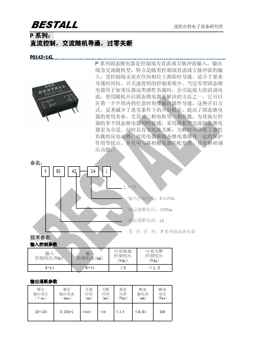
P0142-14L
P系列固态继电器是控制端为直流或方脉冲波输入,输出
端为交流随机型,特点是随着控制端直流或方脉冲波的输
入,受控制端无论在任何相位上都即时导通。
适合于要求
导通时间短、开关速度快的控制系统中。
当过零型固态继
电器用于如变压器这类感性负载时,会引起很大的浪涌电
输出通断参数
额定输出电压(Vac)
额定
输出电流
(Aac)
开通
时间
(ms)
关断
时间
(ms)
通态
压降
(Vac)
断态
漏电流
(mA)
瞬态
电压
(Vac)
28-4200.030-1<0.01<10≤1.5≤0.04800
一般参数安装形式直插
PCB
介质耐压(Vac)绝缘电阻(MΩ)
工作温度(℃)频率范围(Hz)
≥2500
500
-30-80
45-70。
平高东芝252kV断路器说明书
增压状态正常区域(绿色)
警告线(红色)
虹吸管
B-1:液压操作缸
B-20:油泵
B-22:透气帽
B-55:油箱
B-26:油标
图8油位
4 原理
4.1
图9示意了单压式气体断路器的操作原理。
4
(a)当给出分闸指令时,液压操作缸(B-1)分闸侧的高压油排出,操作活塞(B-2)被向上驱动(触头分闸方向)。参阅4-2节。
压气室是由可移动的压气缸(A-61)和一个固定的压气活塞(A-62)组成。压气缸通过一根操作拉杆(A-63)和一根绝缘拉杆(A-73)与各自的油-液压操作缸(B-1)上的驱动杆(B-10)相连。另外如上所述,压气缸与动触头装配相连,因此,动触头装配和压气缸通过液压操作缸一起被驱动。
3.4
操作机构(见图4、图5),对于每一相,液压机构和辅助设备安装在上盖的对侧。
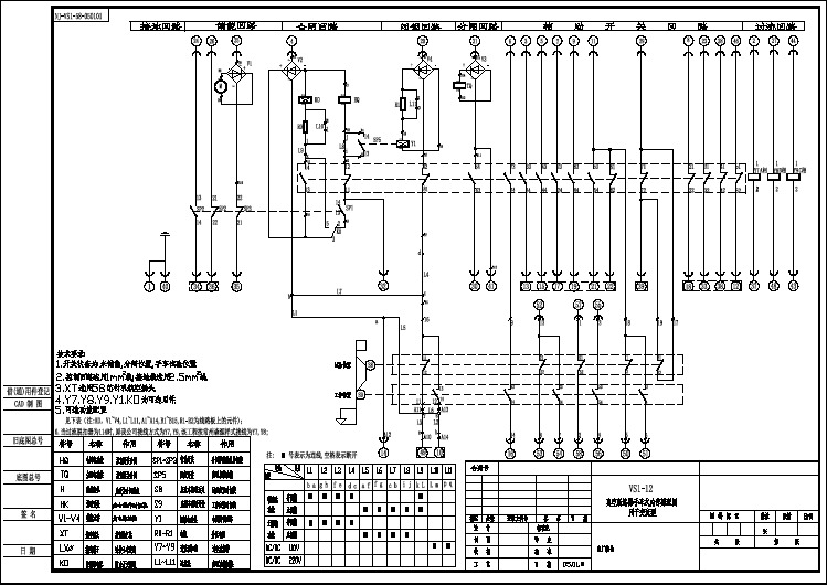
图,参阅经过认可的附图。52Y:常闭辅助继电器52C;合闸线圈
A1-A14:常态“a”触点B1-B14;常态“a”触点
63QFX:液压开关分闸联锁47X.Y:相差辅助继电器
63QEX:液压开关合闸联锁3-52: 手动操作开关
63QEX:SF6气体密度开关的分闸/合闸联锁
47T:相差时间继电器
合闸回路跳闸保护装置 监控系统
操作缸单元装配有一个油泵单元(B-20)、一个油压表(B-60)、油压开关(B-50)、一个油泵电机(B-24)、一个排油阀(B-31)(通常处于关闭状态)、一个泄压阀(B-30)、一个通气孔盖(B-22)、一个液压油泵(B-)侧面的油标(B-26)。油过滤器(B-27)安装在油箱里面。关于油箱的油位指示,详见图8。
4.
图10a和图10b示出液压操作机构的操作原理。
设备控制器_真空断路器手车式内部原理图
PJG系列矿用隔爆兼本质安全型永磁机构高压真空配电装置使用说明书样本

PJG系列矿用隔爆兼本质安全型永磁机构高压真空配电装置使用说明书中国·华夏防爆电气有限公司1适用范围与用途PJG系列矿用隔爆兼本质安全型永磁机构高压真空配电装置( 以下简称配电装置) , 适用于煤矿井下和其它周围介质中含有爆炸性气体( 甲烷混合物) 的环境中, 对额定频率50Hz、额定电压10kV或6KV、额定电流至630A的三相交流中性点不直接接地的高压供电系统的过载、短路、接地( 漏电) 、绝缘监视、过压、欠压、三相不平衡等故障进行保护, 并可作为直接起动高压电动机用。
本配电装置选用技术先进的智能化多功能综合保护器, 保护可靠灵敏, 测量精度高, 配合中文菜单式人机交互界面, 显示信息丰富, 操作直观简便。
本配电装置具有RS485串行通讯口( 本安设计) , 可实现与同种配电装置通讯组网, 上位配电装置可查询本配电装置的各种运行方式与参数、运行状态、发生故障后故障的有关信息。
与配电装置组网通讯的各关联设备必须是取得相关合格证书, 并经过联机试验合格后的产品, 不得连接未试验产品。
配电装置可在下列环境条件下使用:a.海拔高度不超过1000m, 大气压力80~110kPa;b.环境温度为-20℃~+40℃;c.空气相对湿度不大于95%(+25℃时) ;d.无强烈震动和冲击振动;e.与垂直面的安装倾斜度不超过15°;f.在无足以腐蚀金属和破坏绝缘的气体和蒸气的环境中;9.无滴水和水浸入的地方;h.在有煤尘和爆炸性气体的危险场所i.污染等级: 3级;j.安装类别: Ⅲ类k.使用类别: A2型号含义P J( KV)( A)隔爆兼本质安全型配电装置主回路接线方案符号含义a: 有两个电源进线端, 一个负荷出线端;b: 有一个电源进线端, 另一个封闭, 一个负荷出线端;c: 仅适用于联台使用, 本身不进线, 电源母线由另台进入, 有一个负荷出线端;d: 仅适用于在联台时做联络开关及两端做受电开关使用, 负荷侧不出线。
PCS-915母线保护说明书(220KV)

PCS-915 微机母线保护
技术和使用说明书
本说明书适用于兰溪变 220KV 母线保护程序版本 南瑞继保电气有限公司版权所有
本说明书和产品今后可能会有小的改动,请注意核对实际产品与说明书的版本是 否相符。
更多产品信息,请访问互联网:
目录ห้องสมุดไป่ตู้
1 概述.........................................................................................................................................................1
3213goose断链告警的处理方式除了确实由链路问题或交换机异常导致的goose中断情况以外正常情况goose断链主要有两种情况一是间隔检修导致的goose断链报警如线路保护检修导致母差报该线路保护goose断链告警二是备用间隔问题如母差的备用间隔因暂无接入装置导致报goose为控制上述两种情况下装置不报警干扰运行人员同时对于确实由链路问题或交换机异常导致的goose中断及时准确报出并能通过报警信号引起运行人员的注意我们采用如下的goose断链报警的处理方案
施耐德电气- NZM 1-4系列塑壳断路器,至1600A- 中文版说明书

NZM 1-4系列塑壳断路器目录1.1系统综览1.2产品概述1.3断路器1.4隔离开关1.6用于北美地区的断路器1.11 断路器,隔离开关NZM 1-4系列塑壳断路器断路器,隔离开关 (2)断路器,隔离开关,3/4极 (4)热磁式脱扣器,3极磁式3极短路脱扣器电子式脱扣器,3极热磁式脱扣器,4极电子式脱扣器,4极 (6) (10) (12) (16) (20)热磁式脱扣器,3极磁式3极短路脱扣器电子式脱扣器,3极 (28) (32) (34)辅助触点带螺钉端子带弹簧压接端子欠压脱扣器带螺钉端子分励脱扣器带螺钉端子门联动旋转手柄门联锁功能的旋转手柄,用于具有UL/CSA认证的NA开关旋转手柄门联锁功能的旋转手柄主开关旋转手柄组件附件机械联锁 (46) (48) (55) (62) (64) (66) (67) (68) (70) (72)3极4极 (24) (25)1.7用于北美地区的塑壳开关3极 (40)1.5产品概述用于北美地区的断路器、隔离开关,3极 (26)1.8技术概述用于1000V AC的断路器和隔离开关,3极 (41)1.9断路器用于是1000V,3极 (42)1.10 安装布线辅助触点,脱扣指示辅助触点 (44)结构紧凑,仅四种电流壳架等级具有3极和4极产品额定电流达到1600A 多种安装方式可选择50℃环境温度下无需降容适用于世界范围市场,通过IEC、UL/CSA,CCC认证安全可靠地对电能进行分配、通断和控制,应用于工业、建筑和机器设备制造业。
创新的保护理念,具有故障诊断和通信功能。
断路器系列NZM1到NZM4• •• • ••Page 4具有故障诊断数据记录和调试功能在运行中可进行负荷分析诊断软件NZM-XPC-SOFT• • • 下载网址:/en/support/ser-viceresult.jsp合闸延时短,60~100 ms 可加锁、铅封,确保安全操作远程操作机构• • Page 74不同型号具有统一的开孔尺寸自动调节,定位中心位置侧面操作功能,节约了主开关的安装空间门联动旋转手柄••• Page 62同一型号的辅助触点安装在不同位置,具有不同功能减少了型号种类,降低了库存要求直接卡装,节约了安装成本标准/脱扣指示辅助触点与Titan系列产品通用• • • Page 46NZM 1-4系列塑壳断路器产品描述塑壳断路器NZM 1,2,3,4,至1600A产品描述NZM 1-4系列塑壳断路器目录 1.11 断路器,隔离开关1.12 选择性保护,线路保护,后备保护NZM 1-4系列塑壳断路器平形联动机构远程操作机构插拔式单元,抽屉式单元NZM1接线端子NZM2接线端子NZM3接线端子NZM4接线端子附件绝缘外壳接地保护脱扣器漏电保护附件多功能适配元件........................................................................................................73......................................................................................................74....................................................................................76....................................................................................................92....................................................................................................96..................................................................................................100..................................................................................................106..................................................................................................................114..............................................................................................................116...............................................................................................118....................................................................................................119. (121)断路器脱扣特性断路器允通特性剩余电流继电器的频率响应.................................................................................................127.................................................................................................131 (135)断路器隔离开关塑壳开关功率耗散接线能力辅助触点辅助触点的安装,ON-OFF时间差欠压脱扣器,分励脱扣器远程操作机构,电容单元数据管理界面(DMI模块)总线连接剩余电流继电器压力释放方向,最小安装间隙,管状接线头................................................................................................................136.............................................................................................................141............................................................................................................142............................................................................................................144............................................................................................................146............................................................................................................148....................................................................149..................................................................................150..................................................................................151.................................................................................152...........................................................................................................153................................................................................................155 (156)在进线断路器NZM...和出线断路器FAZ-B(C),PKZ...之间实现选择性保护在进线断路器NZM...和出线断路器NZM...之间实现选择性保护线路保护,后备保护................................................................................122........................................................................................................124 (126)1.14 技术数据1.13 脱扣特性机械联锁用于远程操作机构的机械联锁 (157) (158)1.15 安装设计NZM型号说明隔离开关型号说明....................................................................................................204.. (205)1.17 型号规则1.16 尺寸断路器,隔离开关 (159)NZM 1-4系列塑壳断路器系统总览NZM 1-4系列塑壳断路器系统总览1.11.1断路器,隔离开关断路器,隔离开关断路器额定持续电流,最大1600 A 分断能力25, 50, 100, 150 kA 于415 V过载保护和短路保护范围可调节时间选择性可调节接地保护低压系统保护,电缆保护,电动机保护,发电机保护3极和4极,IEC/EN 60947隔离开关额定持续电流,最大1600 A 远程脱扣功能,需带欠压或分励脱扣器3极和4极,IEC/EN 60947附加功能安装附件标准辅助触点随主触头动作而动作用于脱扣指示和电气互锁功能脱扣指示辅助触点指示因过载、短路和欠压而产生的脱扣提前闭合辅助触点用于电气互锁和减负荷功能,及在主回路/急停电路应用中欠压脱扣器的提前闭合电压脱扣器电压脱扣器·瞬时·延时分励脱扣器垫块欠压线圈的延时单元门联动旋转手柄门·可加锁·有门联锁功能用于柜体侧面安装的断路器旋转手柄延长杆可以切割成任意长度旋转手柄可加锁远程操作机构通过2线和3线控制实现ON,OFF 复位上下扳动手柄的锁定装置侧面操作手柄数据管理界面(DMI模块)可以查询诊断数据和运行数据记录电流值利用电子式脱扣器对断路器进行参数设置和控制EASY-LINK-DS数据插头PROFIBUS-DP通讯接口1165538971817241125252613, 151214161920212223241011控制回路端子顶部或底部管状式接线端子,铜线或铝线标准配置控制回路端子盒式接线端子框架1的标准配置安装干开关壳体内端子盖在使用电缆接线片,母排或管状接线端子处,防止直接接触安装支架NZM1-XC35用于35 mm导轨NZM1-XC75用于75 mm导轨后部接线端子插拔式和抽屉式单元绝缘框用于上下扳动式手柄,带有旋转驱动机构的旋转式手柄和远程操作机构外部警示牌/显示板指触防护等级为IP2X的防护盖用于盒式接线端子指触防护等级为IP2X的防护盖用于相间隔板NZM 1-4系列塑壳断路器产品概述NZM 1-4系列塑壳断路器产品概述1.21.2断路器隔离开关适用于世界范围的断路器和隔离开关的选型,从第26页起。
NZM1-4

短路瞬时保护固定值 Ii 350 A 于In = 20 - 32 A 1280 A 于In = 160 A (NZM1)
适配的接线端子:
盒式接线端子(标配)
3极:NZM1-XKC;
1件
NZM2-160-XKC;
NZM2-250-XKC
4极:NZM1-4-XKC;
NZM2-4-160-XKC;
1件 符合IEC/EN 60947-2, 满足ROHS环保标准
过载保护值 Ir 连续可调 0.8 - 1 x In (出厂设置值 0.8 x In)
短路瞬时保护值 Ii 连续可调 6 - 10 x In (出厂设置值6 x In) NZM...-A40: 8 - 10 x In (出厂设置值8 x In)
闭合
电压脱扣器
25
电压脱扣器
瞬时
延时
分励脱扣器
垫块
10
欠压线圈的延时单元
26
门联动旋转手柄 可加锁 有门联锁功能
13,15
用于柜体侧面安装的断路器旋转手柄 12
延长杆
14
可以切割成任意长度
旋转手柄
16
可加锁
远程操作机构
19
通过2线和3线控制实现ON,OFF, 复位
上下扳动手柄的锁定装置
20
侧面操作手柄
脱扣单元: - A: 热磁式配电保护 - AE: 电子式配电保护 - VE: 电子式选择性配电保护
额定电流: 20 A 至1250 A
A P 系列
B 2 - 4 - A
200
B 2 - A
200 - -A P
4 系统总览
断路器, 隔离开关
4
3
5
26
2
人民电器 JS14C、JS14S 系列时间继电器 产品说明书
JS14系列数显式时间继电器,适应于交流50/60Hz ,额定控制电源电压380V 以下或直流24V 的控制电路中作时间控制元件,按预置的时间接通或分断电路。
产品符合:JB/T10047 、GB/T 14048.5、IEC60947-5-1标准。
产品型号:JS14S 、JS14S-C (JS14C )、JS14S-A (DH14S );□ 电源电压:AC :36V 、48V 、110V 、220V 、380V ,50/60Hz ;DC24V ,AC/DC: 85V~265V 。
□ 电源电压范围:电源电压的85%~110%;□ 工作方式:通电延时;□ 触点数量:延时2转换;□ 触点容量:Ue/Ie : AC-15: AC220V/0.75A; AC380V/0.47A; DC-13 220V/0.27A: Ith: 5A ;□ 延时精度:≤1%;□ 复位时间:不大于100ms ;5□ 电气寿命:1*10;6□ 机械寿命:1*10;□ 功耗:≤3VA ;□ 安装方式:面板式 。
□ □ □ 海拔高度不超过2000m ;□ 大气条件:最高温度为+40℃时,空气相对湿度不超过50%,在较低的温度下可允许有较高 的相对湿度,对由于温度变化偶尔产生的凝露应采取特殊的措施;□ 污染指数:3;□ 安装类别:Ⅱ;□ 请不要将继电器安装在以下环境中:强烈的振动以及冲击的地方;强烈的碱性或是酸性的场所;太阳直射的地方;有强烈的磁性和高压干扰的地方。
周围空气温度:上限值不超过+40℃,下限值不超过-5℃,24小时的平均值不超过+35℃;正常工作条件和安装条件主要技术数据产品概述选型指南JS14C 、JS14S系列时间继电器079图2、JS14CL JS14S-C (JS14C )接线图56437821~~1287346591011复零暂停图1 JS14S 、JS14S-(DH14S )接线图注意:复零和暂停端子切勿从外输入电压JS14S 、JS14S-C (JS14C ) 、JS14S-A (DH14S )外形及安装尺寸接线图外形及安装尺寸 用户在订货时应注明继电器型号、规格、额定电压和数量。
JRS14-001继电器开关安装和操作手册说明书

JRS14-001Relay SwitchInstallation and Operating ManualRev. CJupiter Avionics Corporation1959 Kirschner RoadKelowna BCCanada V1Y 4N7Tel: +1 7784782232Toll-Free: 1 8554782232Installation and Operating ManualCopyright 2013 Jupiter Avionics Corp.All rights reservedJupiter Avionics Corporation (JAC) permits a single copy of this manual to be printed or downloaded for theexpress use of an installing agency. Any such electronic or printed copy of this manual must contain the complete text of this copyright notice. Any unauthorized commercial distribution of this manual is strictly prohibited. Except as described above, no part of this manual may be reproduced, copied, transmitted, disseminated, downloaded, or stored in any storage medium for any purpose without the express prior written consent of JAC.Record of RevisionsRevisionRev Date DescriptionECR A Feb 2013 Initial Release. Serial number 1001 and higher1019, 1021 B Feb 2014 Modified Certification Statement2590 C Oct 2014JRS14-001 only. Modified Voltage Requirements3032Prepared:MPBChecked: Approved:Installation and Operating ManualTable of ContentsSECTION 1 - DESCRIPTION (1)1.1 System Overview (1)1.2 Features Overview (1)1.2.1 Functionality (1)1.2.2 Emergency procedures (1)1.3Inputs and Outputs (2)1.3.1 Inputs (2)1.3.1 Outputs (2)1.4 Specifications (2)1.4.1 Electrical Specifications (2)1.4.2 Physical Specifications (3)SECTION 2 – INSTALLATION (4)2.1Introduction (4)2.2Continued Airworthiness (4)2.3Unpacking and Inspecting Equipment (4)2.3.1Warranty (4)2.4Installation Procedures (4)2.4.1Cabling and Wiring (4)2.4.2Mechanical Installation (5)2.4.3Post Installation Checks (5)2.5 Adjustments (6)2.6 Installation Kit (6)2.6.1 Recommended Crimp tools (6)2.7 Installation Drawings (6)SECTION 3 – OPERATION (7)3.1Introduction (7)Appendix A - Installation Drawings ..................................................................................................................... A1 A1Introduction ............................................................................................................................................... A1 A2Installation Drawings ................................................................................................................................ A1JRS14-001 Relay SwitchSECTION 1 - DESCRIPTION1.1 System OverviewThe JRS14-001 Relay Switch is a compact, high-density, bulkhead-mounted remote switching unit that provides fourteen “C style” contacts to handle the switching requirements of navaid, audio, and other interface applications. It allows up to 14 data or audio lines to be transferred with a single control line.1.2 Features OverviewThe JRS14-001 features industry standard interconnects to allow easy field upgrades.The JRS14-001 provides switching for 14 contacts of information, organized as three groups of two 2PDT relays and one group of one 2PDT, each with an individual key line. Each group can be used independently, or can be picked as one group (14 contact sets) by applying the required logic level to the appropriate ALL GROUP KEY line.These relay switches can be used for applications from dry circuit to 0.5 A switching, but are limited to a maximum of 30 Vdc. They can be operated from +18 to +33 Vdc without changing the interconnect.All interconnect and relay contacts are gold plated. Relays are sealed, high vibration rated (50g shock), dry nitrogen filled units.All relay switches have a contact rating of 1 amp/30 Vdc1.2.1 FunctionalityThe JRS14-001 provides remote switching of navigation or audio signals to allow system expansion or interconnection. Once installed, it operates independently to provide the required switching functions without any operator action.1.2.2 Emergency proceduresThe JRS14-001 does not affect the emergency procedures of the aircraft. If the unit is used to switch navigation signals, flight personnel should be made aware of its function.Installation and Operating Manual1.3Inputs and OutputsRefer to the JRS14-001 connector map for the mating connector designators and pin assignments for the input and output signals.1.3.1 InputsRefer to the JRS14-001 connector map drawing for the mating connector designators and contact assignments for the input signals.InputTypeQuantityGROUP KEY active low 4ALL GROUP KEYactive low 1 POWER INPUT and POWER GROUND power 2 Common signal inputsrelay contact141.3.1 OutputsRefer to the JRS14-001 connector map drawing for the mating connector designator and contact assignments for the output signals.Output TypeQuantity Normally open signal outputs 14 Normally closed signal outputs 14 Bias voltage output contacts11.4 Specifications 1.4.1Electrical SpecificationsPower InputNominal voltage 28 Vdc Maximum voltage 30.3 Vdc Minimum voltage 22.0 Vdc Emergency voltage 18.0 VdcInput current≤ 0.2 A max @ 28 Vdc1.4.1.1 Audio PerformanceRated Input LevelAudio rated input level7.75 Vrms ± 10% 1.0Arms maxRated Output LevelAudio rated output level7.75 Vrms ± 10% 1.0 Arms maxAudio Frequency ResponseAudio output audio frequency response≤ 3dB from 300 to 6000 Hz Distortion CharacteristicsAudio output distortion at rated power≤ 10% Audio output distortion at 10% of rated power≤ 3%Typerelay contact relay contact voltage sourceInstallation and Operating Manual Input to output Crosstalk and Bleed-through LevelInput to output Crosstalk ≤55 dBInput to Input Crosstalk LevelInput to Input crosstalk ≤60 dBAudio Noise Level without SignalNoise level below the rated output ≥ 60 dB1.4.1.2 Control Signal PerformanceDiscrete SignalsActive low control input shall be active when the signal is ≤ +3 VdcActive low control input shall be inactive when the signals is ≥ +10 VdcActive low control input signals, when active, shall source ≤ 20 mAOutput signals, when active, shall sink ≤ 1 A1.4.2 Physical SpecificationsHeight (maximum) 1.25" [31.8 mm]Overall depth (maximum) 2.30" [58.4 mm]Width (maximum) 4.50" [114.3 mm]Weight (maximum) 0.35 lb [0.15 g]Enclosure material brushed aluminum withconversion coatingConnectors One 50 pin D-Sub male, V5lockingMounting 4 ea 10-32 screwsBonding ≤ 2.5 mΩInstallation kit part number INST-JRS1xJRS14-001 Relay SwitchSECTION 2 – INSTALLATION2.1 IntroductionThis section contains unpacking and inspection procedures, installation information, and post-installation checks.2.2 Continued AirworthinessMaintenance of the JRS14-001 is on condition only. Scheduled inspection and/or periodic maintenance of this unit is not required.2.3 Unpacking and Inspecting EquipmentUnpack the equipment carefully. Check for any obvious shipping damage and report any problems to the relevant carrier. Confirm that the Certificate of conformity or release certification is included. Complete the on-line warranty card from the Jupiter Avionics Corporation (JAC) website – /warranty.2.3.1 WarrantyAll products manufactured by JAC are warranted to be free of defects in workmanship or performance for 2 years from the date of installation by an approved JAC dealer or agency. This warranty covers the cost of all materials and labour to repair or replace the unit, but does not include the cost of transporting the defective unit to and from JAC or its designated warranty repair centre, or of removing and replacing the defective unit in the aircraft. This warranty does not cover failures due to abuse, misuse, accident, or unauthorized alteration or repairs.THIS WARRANTY IS VOID IF THE PRODUCT IS NOT INSTALLED BY AN AUTHORIZED JAC DEALER. If the on-line warranty card is not completed, the product will be warranted from the date of manufacture.Contact JAC for return authorization, and for any questions regarding this warranty and how it applies to your unit(s). JAC is the final arbiter concerning warranty issues.2.4 Installation Procedures2.4.1 Cabling and WiringAll wire shall be selected in accordance with the original aircraft manufacturer’s maintenance instructions, or AC43.13-1B Change 1, Paragraphs 11-76 through 11-78. Unshielded wire types shall qualify to MIL-W-22759 as specified in AC43.13-1B Change 1, Paragraphs 11-85, 11-86, and listed in Table 11-11. For shielded wire applications, use Tefzel MIL-C-27500 shielded wire with solder sleeves (for shield terminations) to make the most compact and easily terminated interconnect. Follow the Connector Map in Appendix A of this manual.Allow 3” from the end of the shielded wiring to the shield termination to allow the connector hood to be easily installed. Refer to the Interconnect drawing in Appendix A of this manual for shield termination details. Note that this unit has a‘clamshell’ hood that is installed after the wiring is complete.Maintain wire segregation and route wiring in accordance with the original aircraft manufacturer’s maintenance instructions.Installation and Operating Manual Unless otherwise noted, all wiring shall be a minimum of 24 AWG, except power and ground lines, which shall be a minimum of 20 AWG. Refer to the Interconnect drawing for additional specifications. Check that the ground connection is clean and well secured, and that it shares no path with any electrically noisy aircraft accessories such as blowers, turn-and-bank instruments, or similar loads.2.4.2 Mechanical InstallationThe JRS14-001 can be mounted in any attitude and location with adequate space and sufficient clearance for the connector and wiring harness. It requires no direct cooling and no shock or vibration isolators are required.2.4.2.1 Installation ConsiderationsIf the JRS14-001 is to be used for NAV switching, for instance linking two sources to a common indicator, this must be clearly marked and placarded in the aircraft. External annunciation of any NAV source must comply with section2.4.2.2 of this manual.If the unit is to be used for GPS/VLF switching, it may be necessary to wire the unit to ensure that it returns to the VOR/ILS mode when the navigation receiver is tuned to an ILS frequency. Check local aviation regulations regarding this requirement.NOTE: ILS reversion mode for NAV/GPS installations is not applicable in Canada.2.4.2.2 External Switches and LampsAll switches and/or annunciators must be selected to suit the application. A single pushbutton or toggle switch may be used to supply the ALL GROUP KEY line to allow all lines to be selected together. If a single switch or lamp assembly is used to replace the transfer switch and annunciators, it should be a lighted pushbutton switch (SPST/SPDT) with a positive action (i.e. push on/push off) with two legends to match the required NAV functions.If the unit is to be used as audio key relays for boom mics etc., the unit can be triggered by in-line drop cords or similar ways that supply an input to the appropriate key line.If it is to be used as a NAV selector, annunciator lights should be connected through one or more relay contacts to ensure correct indication of the actual relay contacts.2.4.3 Post Installation Checks2.4.3.1 Voltage/Resistance checks.Do not attach this unit until the following conditions are met:a) Check P1 pin 17 for +28 Vdc relative to ground.b) Check P1 pin 34 for continuity to ground (less than 0.5 Ω).c) Check P1 pins 47 - 50 for continuity to ground (less than 0.5 Ω) when the relevant switch is closed.d) Check all pins for shorts to ground or adjacent pins.2.4.3.2 System OperationAll operation is described with aircraft electrical power supplied, unless stated otherwise.Individual Relay Key OperationThe individual relay common contacts connect to the Normally Open signal contacts when theGROUP (1 thru 4) KEY input is active.The individual relay common contacts connect to the Normally Closed signal contacts when theGROUP (1 thru 4 and ALL) KEY input is not active.All Relay Key OperationThe all relay common contacts connect to the Normally Open signal contacts when theALL GROUP KEY input is active.Installation and Operating ManualBias Resistor OperationThe bias resistors provide an electrical current on a continuous basis2.4.3.3 Power on Checks.Power up the aircraft’s systems and check that all switching functions transfer correctly with the appropriate relay action. If the internal flag bias is used for indicator interfacing, ensure that this function works correctly, and only in the selected or transferred position.When all performance checks are satisfied, complete the necessary regulatory documentation before releasing the aircraft for service.2.5 AdjustmentsThe JRS14-001 has no internal mechanical adjustments.2.6 Installation KitThe kit required to install this unit is not included with the unit.The JRS14 requires one installation kit (Part # INST-JRS1x) which consists of the following:Quantity Description JAC Part #1 D-sub 50-pin Connector Assembly CON-3420-00501 TAG ring CON-5500-06251 Heatshrink Tubing WIR-HTSK-10002.6.1 Recommended Crimp toolsConnector Type Hand crimp tool Positioner Insertion/extraction tool Positronic 9507 9502-3 M81969/1-042.7 Installation DrawingsThe drawings and documents required for Installation can be found in Appendix A of this manual..JRS14-001 Relay SwitchSECTION 3 – OPERATION3.1 IntroductionThe JRS14-001 has no operator controls.If any switches or indicators have been installed to control or indicate the function of the unit, confirm their operation with the installing agency and ensure that the relevant information has been added to the flight manual where necessary.JRS14-001 Relay SwitchInstallation and Operation ManualAppendix A - Installation DrawingsA1 IntroductionThe drawings necessary for installation and troubleshooting of the JRS14-001 Relay Switch are in this Appendix, as listed below.A2 Installation DrawingsDOCUMENT REVJRS14-001 Connector Map BJRS14-001 Interconnect BJRS14-001 Mechanical Installation BTITLEPREPARED CHECKEDRelay Switch 14 ContactsTAT1234567891011121314151617181920212223242526272829303132333435363738394041424344454647484950+28 V D C P O W E RP O W E R G R O U N DP150 PIN FEMALE DMIN MATING CONNECTORGROUP 1VIEW IS FROM REAR OF MATING CONNECTORB AC D B A C D B A C DGROUP 2GROUP N .O . B G R O U P 1 K E Y N .C . B G R O U P 2 K E Y C O M M O N B G R O U P 3 K E Y G R O U P 4 K E Y A L L G R O U P K E Y0.5 m A F L A G B I A SC O M M O N AN .C . AN .O . AGROUP 4CONTACTCONTACT CONTACT CONTACT JACDS 08-28-14JACTITLEPREPARED CHECKEDRelay Switch 14 ContactsTATJRS14-001 INTERCONNECT WIRING NOTESNOTES ALL WIRE SIZE SHOULD BE 24 AWG MIN UNLESS OTHERWISE SPECIFIED. UNSHIELDED WIRE SHOULD BE SELECTED PER FAA AC43.13-1B CHANGE 1 PARA 11-76 TO 11-78. WIRE TYPES SHOULD BE IN ACCORDANCE WITH MIL-W-22759 AS DESCRIBED IN FAA AC43.13-1B CHANGE 1 PARA 11-85 AND 11-86 AND LISTED IN TABLE 11-11 OR 11-12. ALL SHIELDED CABLE SHOULD BE IN ACCORDANCE WITH MIL-DTL-27500 (REVISION H OR LATER).CONNECTION TO AIRFRAME GROUND SHOULD BE MADE WITH 20 AWG WIRE. LENGTH NOT TO EXCEED 3 FT (0.91 M).1.2JACDS 08-28-14JACJRS14-001J1PREPARED TAT+V160.5 mA FLAG BIAS38COMN.C.21N.O.437COM N.C.20N.O.347GROUP 1 KEY+V 17+28 VDCVOLTAGE REG1A34POWER GROUND 20 AWG 20 AWG36COM N.C.19N.O.235COM N.C.18N.O.1CONTACT AGROUP 1CONTACT BCONTACT C CONTACT D 42COMN.C.25N.O.841COM N.C.24N.O.748GROUP 2 KEY40COM N.C.23N.O.639COM N.C.22N.O.5CONTACT AGROUP 2CONTACT BCONTACT CCONTACT D46COMN.C.29N.O.1245COM N.C.28N.O.1149GROUP 3 KEY44COM N.C.27N.O.1043COM N.C.26N.O.9CONTACT AGROUP 3CONTACT BCONTACT CCONTACT D50ALL GROUPS KEYGROUP 2 KEY GROUP 1 KEY GROUP 3 KEY P150 PIN FEMALE DMIN MATING CONNECTOR32COM+V 33GROUP 4 KEY N.C.31N.O.30N.C.14N.O.13CONTACT AGROUP 4CONTACT B15COM 2GROUP 4 KEY+V+V+V+V+V+V。
一二次融合 KV柱上断路器技术规范
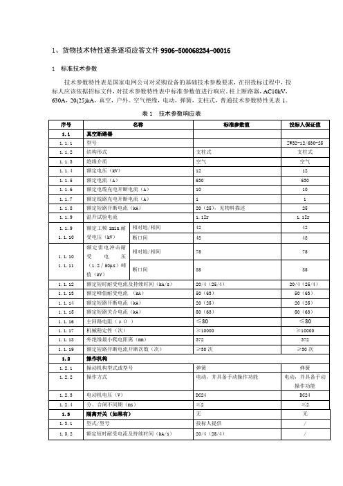
1、货物技术特性逐条逐项应答文件9906-500068234-00016
1 标准技术参数
技术参数特性表是国家电网公司对采购设备的基础技术参数要求,在招投标过程中,投标人应该依据招标文件,对技术参数特性表中标准参数值进行响应。
柱上断路器,AC10kV,630A,20(25)kA,真空,户外。
空气绝缘,电动,弹簧,支柱式,普通技术参数特性见表1。
表1技术参数响应表
2、配套配置红绿黄三色绝缘罩。
3、括号内数值为分断能力25kA的柱上断路器对应的参数。
2主要组部件材料
2.1 主要组部件材料表见表2。
表2主要组部件材料表
3使用环境条件表
表4使用环境条件表
注表中“项目单位要求值”为正常使用条件,超出此值时为特殊使用条件,项目单位可根据工程实际使用条件进行修改。
红苏电气科技有限责任公司生产的柱上断路器符合《使用环境条件表》标准要求。
ABB开关柜UniSwitch产品说明书

1
4
2
3
1- 母线室
母线室布置在柜的上部。在母线室中主母线连接在一起,贯穿 整排开关柜。
2- 开关室
开关室内装有一个3工位负荷开关,负荷开关的外壳为环氧树脂 浇注而成,充六氟化硫(SF6)气体为绝缘介质,在壳体上设有观 察孔。负荷开关上可根据客户要求装设带报警触点的SF6气体压 力监视器。
4- 操动机构、联锁机构和低压控制室
UniSwitch 间隔式金属封闭开关设备 设计原理 03
2.应用领域
UniSwitch开关柜能为中压系统提供最好的解决方案,外形尺寸 小巧紧凑。
其优点是:
- 技术参数的灵活性和便于后期改造升级。 - 可选配全套控制、测量和保护系统。
UniSwitch开关柜 用于以下配电场所:
环网柜(RMU) 用于以下配电场所:
带联锁的低压室同时起到控制盘的作用。低压室内装有带位置 指示器的弹簧操动机构和机械联锁装置,也可装设辅助触点、 跳闸线圈、紧急跳闸机构、电容式带电显示器、钥匙锁和电动 操动装置,同时低压室空间还可供装设控制回路、计量仪表和保 护继电器,750mm宽柜设有两个相同的低压室,可装更多附件。 整个UniSwitch开关柜可分成上下两个部分,柜的上部包括母线 室、负荷开关、操动机构和低压室,与下部电缆室分隔开来。 因此,可以安全、方便地对装于上部单元内的设备进行检修及 改造,并可更换整个上部单元。
基本设备
上部单元, 包括: - 3工位负荷开关 - 配机械式位置指示装置的操动机构 - 母线室壳体 - 集成式低压室 - 联锁装置 - 母线 - 提示型显示器 DXN-T
下部单元, 包括: - 电缆室壳体 - 配电缆支撑件的电缆底板
开关柜的可选件
- 强制闭锁型显示器DXN-Q - 各位置的辅助触点:2个常开+2个常闭 - 带报警触点的SF6气体压力监视器 - 压力指示表 - 电动操动装置 - 电流互感器 - 电压互感器 - 压力释放通道 - 控制电缆通道 - 避雷器 - 故障指示器
Pcon PCON-C CG CF 控制器 定位型 说明书 第五版

[设置、运行、维护]
● 使用产品时,请根据需要使用防护手套、防护眼镜及安全靴等,以确保安全。
[废弃]
● 产品无法使用或不需要时,请作为工业废弃物作适当废弃处理。
其 他
■ 如未能遵守全部“安全注意事项” ,本公司将不承担任何责任。
目录
1. 概要 ................................................................................................................... 1
4. 最新数据的保存提示
本产品采用非挥发性存储器作为位置表和参数的存储媒体。通常情况下切断电源时将会保持数据, 但当非挥发性存储器发生故障时,数据将会丢失。 另外,因其他原因需要更换控制器时,为尽快恢复数据,强烈推荐保存位置表和参数的最新数据。 保存方法如下 : ① 使用联机软件,存储到光盘或软盘中。 ② 制作位置表或参数表,以书面形式保留。
● ● ●
产品出现异常发热、冒烟或异味时,请立即切断电源。继续使用可能导致产品破损或引起火灾。 产品的保护装置(报警)启动时,请立即切断电源。否则可能因产品异常运转导致受伤或产品的 破损及损伤。切断电源后,请查明并排除报警原因,然后重新接通电源。 如果接通电源后产品的 LED 不亮,请立即切断电源。运行端的保护装置(保险丝等)可能未切 断并继续工作。故障修理请委托购买本产品的本公司销售单位。
1
2
3 4
5
CAUTION
②伺服 ON 输入信号(SON)有效 / 无效的选择 本控制器设有伺服 ON 输入信号,以便在 PLC 侧可以对伺服 ON/OFF 进行控制,因此需要选择 该信号有效或无效。 选择方法为在参数 No.21(伺服 ON 输入无效选择)中设定数字 0 或 1。 有效(使用) 无效(不使用) 出厂时设定为 0[有效] 。 ③暂停信号(*STP)有效 / 无效的选择 根据失效保护设计,暂停信号采用常闭接点。 因此,通常情况下需要事先将其调整为 ON 状态。 但考虑到部分不使用该信号的用途,可通过参数进行选择,无需特意将其设定为 ON 状态。 选择方法为在参数 No.15(暂停输入无效选择)中设定数字 0 或 1。 有效(使用) 无效(不使用) 出厂时设定为 0[有效] 0 1 0 1
3 ABB选型价格查询手册 转换开关 低压产品
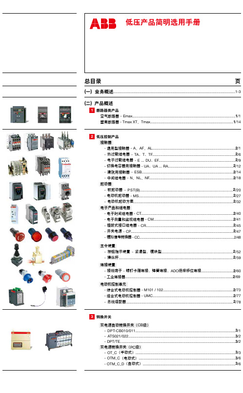
1 断路器类产品 空气断路器 - Emax...................................................................................................1/1 塑壳断路器 - Tmax XT、Tmax................................................................................1/14
连接装置 - 接线端子 - 螺钉卡箍连接、弹簧连接、ADO绝缘移位连接...............................2/60 - 工业连接器........................................................................................................2/69
双电源转换开关(PC级) - OT_C(手动式)................................................................................................3/3 - OTM_C(电动式).............................................................................................3/6 - OTM_C_D(自动式).........................................................................................3/6
继电器样本
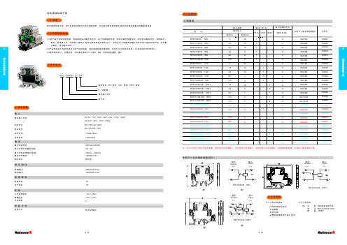
3 型号含义
4 技术参数
输入
额定输入电压
动作电压 返回电压 动作时间 返回时间
输出
最大切换电压 最大切 换电流(阻性负载) 最大 切 换 功 率(阻 性 负 载) 最高动作频率 触点材料
如需要其他规格可按用户要求单独订做继电耦合器返回电压返回时间输入动作电压额定输入电压动作时间最大切换电压最大切换功率阻性负载最高动作频率触点材料测试耐压使用寿命绕组触点机械寿命触头触点电气寿命dc12v24v48v60v110v220vac24v48v110v220v250vac30vdc2kva25kva4kva1800次小时银合金4技术参数输出最大切换电流阻性负载8a10a16a安装方式rtr35环境安装方式107105res72rx支架式设计序号工作环境温度1055储藏温度污染等级257022工作原理和结构继电耦合器用于各种自动保护和自动控制线路作为输出继电器或增加保护和控制回路触点的数量和容量
订货号
767068 767061 767077 767097 767101 767063 767102 767103 767107 767059 767108 767051 767047 767098 767062 767099 767100 767104 767064 767105 767106 767109 767057 767110 767053 767049 767086 767082 767072 767078 767080 767079 767076 767075 767052 767048 767054 767055 767085 767074 767081 767067
EV12s 真空断路器 产品目录

灭弧 动静触头开有倾斜方向相同的斜槽,当电弧电流流过时,将产生较大的圆周 分量,会在触头间形成纵向磁场。在优化的纵向磁场的作用力下,磁场分布 更加均匀,并迅速将聚集电弧分散到整个触头表面,加大了热量的迅速散 失,另外,分散电弧有效利用触头面积,弱化电弧强度,大大减少了对触头 的损伤。在电弧电流自然过零时,电弧熄灭,同时残留的离子、电子和金属 蒸气在微秒级的时间内就可聚集或复合在触头表面或屏蔽罩上,触头间隙的 介质迅速由导体变为绝缘体,间隙中的绝缘强度得到彻底恢复,从而完成电 弧的熄灭。配合操作机构可靠动作,在更短的时间内拉开了触头距离,更加 速了绝缘强度的回复。
EV12s真空断路器选型指南.................................................. 8 产品结构 ............................................................... 8 型号说明 ............................................................... 10 EV12s手车式真空断路器简介 ...............................12 -电气参数 ...................................................... 13 -外形尺寸 ...................................................... 14 EV12s固定式真空断路器简介 ...............................15 -电气参数...................................................... 16 -外形尺寸 ...................................................... 17 EV12s真空断路器附件 .......................................... 18 -控制单元 ...................................................... 19 -指示单元及闭锁单元 .................................... 21
煤矿安标新文件3D受控元件明细表

二〇 一〇 年七月二十二日
产品主要零(元)部件及重要原材料明细汇总表
目录
1 电气设备 .......................................................................................................................................................... 1 1.1 开关与起动器 ....................................................................................................................................... 1 1.1.1 矿用防爆低压交流真空馈电开关 .................................................................................................... 1 1.1.2 矿用隔爆型馈电开关 ........................................................................................................................ 1 1.1.3 矿用防爆高压配电装置 ...........................................................................................................
凯驰电气 KCC8(C)-15kV 系列 交流高压真空接触器 说明书

KCC8(C)-15kV 内首款产品,能完全满足通过总结多年来用户的使用经验,控制电磁铁通过操动机构而实现接簧实现。
根据用户需要可定制快速作机构。
该系列产品结构紧凑、绝缘性能好,二次回路可维护性好,在无需经常维护的条件下仍保证其长久的电气与机械寿命。
欢迎用户选择使用。
凯驰电气气凯驰电气电气气凯产品特点•主回路•真空开关管采用国内知名厂家的产品。
技术成熟,质量可靠,市场信誉好。
•主回路采用高强度DMC (SMC )一次成型的半筒形绝缘结构,刚性好,绝缘强度高,耐污秽性好。
•630A 电流等级采用端面和导电夹双重动端联接,电阻小、温升低、更可靠。
•导电排美观耐用,两端出线有同向或异向二种方式供选择,方便用户使用。
•电磁系统•可选永磁机构或传统电磁机构。
•使用大容量密封辅助开关,大大提高辅助开关的可靠性,使用安全。
•优化动作结构,降低线圈启动功率和保持功率,因而温升低,寿命长,更可靠。
•动衔铁分闸极限位置设置限位缓冲器,消除由于分闸反弹幅值过大带来的事故隐患。
同时辅助开关打头也使用缓冲,降低动作冲击力,提高辅助开关可靠性。
•动作结构•主轴支承灵活,受力无卡滞,轴向窜动小,提高了动作性能和一致性。
•运动端采用二次导向机构,确保真空管动导电杆轴向运动同轴度。
合理的动作机构,提高了接触器性能和可靠性。
使三相同步性、弹跳指标优于同类产品,能完全满足容性负载投切的性能要求。
•增强主触头的接触压力,提高了电性能和动作特性。
指标优于同类产品。
•机械保持装置自成一体,结构合理,使用更可靠。
•方便使用和维护•控制回路接线端子有功能标志,防止接线错误。
可以根据用户需要,将接线端子装于机器的前面或后面,方便接线。
辅助触点数量可根据使用要求组合。
凯驰电气气凯驰电气气凯驰电气凯驰电气凯驰电气凯驰电型号选择指南气凯驰气气驰电技术参数:性能参数单位对应IEC60470:2000/02GB/T14808-2001KCC8-15KCC8C-15额定工作电压(U r )kV4.115额定绝缘水平1min 工频耐受电压(U d )kV 4.255冲击耐受电压(峰值)(U p )kV 4.2110额定频率(f r )H Z 4.350额定工作电流(I e )A 4.101160,250,400,630630额定单个电容器组开断电流(C2类)A —250额定背靠背电容器组开断电流(C2类)A —100短时耐受电流额定短时耐受电流(I k )A 4.510I e 额定峰值耐受电流(I p )kA 4.625I e 额定短路持续时间(t k )s 4.74额定负载和过载特性(类别AC4)100次合闸操作A 4.103,4.10410I e (类别AC4)25次分闸操作A 4.103,4.1048I e 额定耐受过载电流1s A 4.103,4.10415I e 额定耐受过载电流30s A 4.103,4.1046I e 主电路接触电阻μΩ 6.4≤200额定操作频率电气保持次/h4.102,4.105300(机械寿命(合/分循环)100万次)机械保持4.102,4.10560(机械寿命(合/分循环)25万次)电气耐久性(电寿命)AC3万次4.10625(关合电流6I e ,开断电流1I e )AC4万次4.1066(关合电流6I e ,开断电流6I e )二次电路对地绝缘耐压2000V50Hz (1min )控制电路额定电压(U s )(85%~110%)V ac./dc.110V、220V、380V 额定功率(P s )电气保持W启动<1500W 保持<50W机械保持合闸<1500W 分闸<600W操作时间合闸ms ≤200分闸ms≤60辅助开关额定绝缘电压V AC380V 约定发热电流A 10额定工作电压VAC380V ,DC250V额定工作电流或功率AC-12/16A ;AC-15/720V A ;DC-12/5A凯驰电气气凯驰电气气凯驰电气凯驰电气凯驰电气凯驰电选型或使用前请与本公司技术部确认技术参数联系方式:邢工138****5251-5--5-外形及安装尺寸图凯驰电气驰电气凯驰电气凯驰电气凯驰电气凯驰电凯驰电气二次接线原理图•电气自保持•机械自保持凯驰电气气凯驰电气气凯驰电气凯驰电气凯驰电气凯驰电。
- 1、下载文档前请自行甄别文档内容的完整性,平台不提供额外的编辑、内容补充、找答案等附加服务。
- 2、"仅部分预览"的文档,不可在线预览部分如存在完整性等问题,可反馈申请退款(可完整预览的文档不适用该条件!)。
- 3、如文档侵犯您的权益,请联系客服反馈,我们会尽快为您处理(人工客服工作时间:9:00-18:30)。
GT21 外形图
型号选择说明
GT21 W F 26.5VDC
高压接头 W=螺栓连接 S=焊接式
安装
F=法兰式
P=螺栓式
空白=26.5Vdc 12V=12Vd 115V=115Vdc 定购继电器请注明带有线圈电压的型号如上所示,线圈电压会出现在靠近线圈引脚的磁极 片或铭牌上,而不是在继电器的型号上。
线圈电压
©江苏中科国腾科技有限公司
版权所有
本公司保留所有解释权利。
页数 2/2 出版日期:2013-1-28
真空继电器 Data-Sheet-Var iable Capacitor
GT21
www.
TYPE GT-21Vபைடு நூலகம்CUUM RELAYS
GTVAC, today's expert in high voltage relays ,announces the GT21. Abrand new 15kVDoublePoleDouble,SPDT contact seets in one relay Compact 2.5"footprint 50ADC continuos carry current RF rated to 32MHz Hot load swichting capable Threaded HV connections for easy installation
特点:GT21 耐磨钨触点适用于频繁负载操作闭合和断开负载能够有效灭弧;真
空介质,接触电阻低;两种可选安装方式,法兰式和螺栓式,螺栓式或焊接式高 压接头,接线简单,可更换线圈,使产品功能实现多样化,符合或超过 MIL-R-83725 标准
规格号 Specification No.
触点组合形式 Contact Configuration 试验电压 (直流或 50Hz 交流峰值) Test Voltage (DC or AC 50Hz Peak)kV DC or AC 50Hz 额定工作电压(峰值) AC2.5MHz Rated Operating AC16MHz Voltage(Peak) kV AC32MHz DC or AC 50Hz 额定承载电流(有效值) AC2.5MHz Rated Carrying AC16MHz Voltage(RMS) A AC32MHz 接触电阻 Contact Resistance (Ω) 断开的触点间 分 布 电 容 Contact Beteween Open Contacts Capacitance(pf) 触点与外壳间 Open Contacts to Ground 最大动作时间 Operate Time Max. (ms) 最大释放时间 Release Time Max.(ms) 温度范围 Range of Temp.(℃) 冲击级别 Shock, 11ms 1/2Sine(Peak g’s) 振动级别 Vibration ,Peak 10g’s( Hz) 机械寿命 Expected Mechanical Life(×106) 标称重量 Weight (g)
GT21
1C 17 15
30 18 10 6 0.025 0.5 1 15 8 -55~+125 50 10~500 1 84(3)
线圈数据 Coil Parameter
标称电压 Rated Voltage DC(V) 最大吸合电压 Pull-in Voltage Max. DC(V) 释放电压 Dropout Voltage. Min.DC(V) 线圈电阻 Coil Resistance (Ω±10%) z 以上数据在 25℃,海平面条件下测得 12 8 0.5~5 48 24(26.5) 16 1~10 180 115 80 5-50 2900