D20ME主板用户手册
Optoma HD20 用户手册说明书

Optoma factory reset. Optoma projector default password.
able of contentsTable of Contents ...................................................................................1Usage Notice ..........................................................................................2Safety Information .........................................................................................2Precautions....................................................................................................3Eye Safety Warnings ............................... Inhaltszusammenfassung zur Seite Nr. 2 sage otice Safety Information The lightning fl ash with arrow head within an equilateral triangle is intended to alert the user to the presence of uninsulated “dangerous voltage” within the product’s enclosure that may be of suffi cient magnitude to constitute a risk of electric shock to persons. The exclamation point within an equilateral triangle is intended to alert the user to the presence of important operating and maintenance (servicing) instructions in the literature accompanying the Inhaltszusammenfassung zur Seite Nr. 3 sage otice Precautions Please follow all warnings, precautions and maintenance as recommended in this user’s guide. ▀■ Warning- Do not look into the projector’s lens when the lamp is on. The bright light may hurt your eyes. ▀■ Warning- To reduce the risk of fi re or electric shock, do not expose this projector to rain or moisture. ▀■ Warning- Please do not open or disassemble the projector as this may cause electric shock. ▀■ Warning- When replacing the lamp, please allow the unit to c Inhaltszusammenfassung zur Seite Nr. 4 sage otice Do: Turn off and unplug the power plug from the AC outlet before cleaning the product. Use a soft dry cloth with mild detergent to clean the display housing. Disconnect the power plug from AC outlet if the product is not being used for a long period of time. Do not: Block the slots and openings on the unit provided for ventilation. Use abrasive cleaners, waxes or solvents to clean the unit. Use under the following conditions: - In extremely hot, cold or humid Inhaltszusammenfassung zur Seite Nr. 5 sage otice Eye Safety Warnings ▀■ Avoid staring/facing directly into the projector beam at all times. Keep your back to the beam as much as possible. ▀■ When projector is used in a classroom, adequately supervise students when they are asked to point out something on the screen. ▀■ In order to minimize the lamp power, use room blinds to re- duce ambient light levels. 5 English Inhaltszusammenfassung zur Seite Nr. 6 ntroduction Package Overview Unpack and inspect the box contents to ensure all parts listed below are in the box. If something is missing, please contact your nearest customer service center. Power Cord 1.8m Projector with lens cap Lamp N Noottee Due to different applications in each country, 2 × AAA Batteries IR Remote Control some regions may have different accessories. Documentation : User’s Manual Warranty Card Quick Start Card WEEE Card (for EMEA only) 6 POWER Inhaltszusammenfassung zur Seite Nr. 7 POWER Y VIDEO SERVICE VGA/SCART/YPbPr 12V OUT HDMI 1 HDMI 2 Pb Pr SOURCE ntroduction Product Overview Main Unit 5 1 2 3 5 6 4 9 8 7 6 1. Control Panel 6. Tilt-Adjustment Feet 2. Zoom Ring 7. Security Bar 3. Focus Ring 8. Input / Output 4. Zoom Lens Connections 5. IR Receivers 9. Power Socket 7 English POWER SOURCE Inhaltszusammenfassung zur Seite Nr. 8 POWER ntroduction Control Panel 1 2 10 3 4 5 9 7 8 6 1. Source 2. Menu 3.
D20维护和使用手册

D20系列RTU软件使用及维护手册长春华信自动化工程有限公司二零零四年二月第一章D20系列RTU硬件组成D20 RTU系统组成D20系列RTU,硬件由以下几部分组成:●D20主机●D20的I/O模块●通讯单元●辅助电源一、D20主机1.机箱组成D20 M的机箱设计成VME-欧洲卡样式,由以下模块组成:♦D20 M主处理器板(一个平置的双倍欧洲卡槽口)♦D20电源(占三个立式欧洲卡槽口)♦D20M+SS接线板(7个RS232串口,1个维护口,2个HDLC口)机箱采用标准的槽口,提供电缆和串口的接口。
电源开关、测试点和指示灯都装在D20M模块的前面。
2.D20 M的通信接口包括●两个HDLC通信口,用于与外设I/O模块进行通信。
●两个RS-232 9600波特的维护口●七个面向字节的异步RS232通信口。
七个串行口是可编程的、并用于对SCADA/EMS主站的通信与/或对其它串行设备的通信,诸如智能仪表等等。
(1)HDLC口(×2):♦D20 LINK:RTU对D20外设I/O的内部通信♦串行链路:HDLC,250KBPS,RS-485对绞线对,变压器隔离,2线制,半双工,MANCHESTER编码,×.25格式的规约(2)WESMAINT 口♦维护与组态用♦RS232,9600波特,XON/OFF握手(3)七个RS232串行口:♦50至38400波特(可编程)♦TXD,RXD,CTS,RTS,DCD信号♦DB9连接器♦IRIG-B卫星时钟接口3.LED显示主板:♦RUN :绿,正常运行时闪♦HALT:红,起机时闪,正常运行时不亮;若一直亮,表示主板运行故障♦FAIL :红,起机时闪,正常运行时不亮;若一直亮,表示主板运行故障电源:♦-12V:绿♦+12V:绿♦+5V:绿♦+48V:绿背板:♦DS1:绿,+5V指示4.机械方面(1)尺寸♦D20 M的逻辑板:6.3"(16.3CM)×9.187"(23.35CM)——水平安装在D20 M机箱内♦D20 M的端子板:1.75"(4.4CM)×19"(48CM)×8.25"(21CM)[H×W×D](高×宽×深)(2)重量D20 M机箱总成,带有D20 M、D20电源及D20 M端子板,约5.5kg。
ME-20中文说明书
y 清洁本设备之前,请关闭电源并从插 座上拔下 AC 适配器连接线。
y 若怀疑您的地区可能发生雷击时,请 将电源插头拔掉。
y 如果使用不当,电池会发生爆炸或漏 液以及造成损害。为了使用安全,请 阅读并遵循以下事项(11 页) y 严格遵循电池安装操作说明,并确 认电池的正负极点是否正确。 y 避免将新旧电池混和使用,也请不 要将不同类型的电池混和使用。 y 设备如在一段时期内不使用,请将电池取出。 y 如果电池发生漏液,请使用柔软的擦布或纸 巾将电池槽中的液体擦干净,并装入新的电 池。为了避免液体腐蚀您的皮肤,请不要让 漏液接触到您的手或皮肤。千万小心不要使 漏液接触到眼睛,如果液体进入眼睛,立即 使用清水进行冲洗。 y 不要将电池与金属物体放在一起,如圆珠笔、 项链或发卡等。
y 与其他设备进行连接时,请关闭本设备的电 源。这样可以避免设备故障和音箱或其他设 备的损坏。
放置场所
y 请不要将本机直接曝晒在阳光下,或放在 热源旁边,或是放在密闭的车内空间,以 及其它高温物体旁。过高的温度容易造成 机体变形及变色。
y 请勿将橡胶、乙烯基等或类似物品长期放 置于设备上。这类物品可能会导致设备褪 色或外观的损坏。
y 使用后的电池必须遵循您居住区域的 安全处理条例进行处置。
上海乐兰电子有限公司
3
重要注意事项
除了阅读第 2-3 页的“安全使用本设备”,请阅读下文,并遵照执行。
电力供应:使用电池
y 请勿将本设备与其他由逆变器控制的设备 (如冰箱、洗衣机、微波炉或空调)或带有电 机的电器设备共用一个电源输出口。由于电 器设备使用方法不同,产生的电源噪音可能 会导致本设备故障或产生噪音。若无法使用 独立的电源插座,请在本设备与电源输出口 之间安装一个电源噪音滤波器。
大洋ME操作使用培训教程
ME操作使用培训教程1.启动及退出非编系统1.1 启动及退出用户可以双击桌面的ME快捷启动图标,或从开始菜单中启动ME非编系统。
(1)单击屏幕左下方的【开始】按钮,选择【程序】-【Dayang】-【应用程序】-MontageExtreme,即可启动ME。
(2)和其他Windows应用程序一样,ME在启动过程中会出现欢迎界面,图片下方将动态显示出组件装载进度。
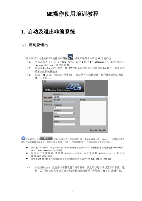
(3)启动了ME之后,将会进入登陆窗口,在这里可以选择新建、打开最近编辑的项目、打开历史项目。
登陆界面中点击按钮,在弹出的“新建项目”窗口中输入项目名称,如myprj,选择相应的视频制式标准和视音频模板,确定后即可新建一个项目.在创建项目时,我们还可以设置登录密码。
●如欲进行标清编辑,请选择PAL制(NTSC制地区请选择NTSC),并根据摄像机类型选择DVSD(Sony)、DV25、DV50(Panasonic)或其他。
●如欲进行高清编辑,请选择HD1080i—25(NTSC地区请选择HD1080i-2997),并选择HD_MPEG2I_100M_48kHz●如使用JVC ProHD系列摄像机,请根据摄像机记录格式选择720 25p、50p或1080 50i(4)在继续弹出的“是否修改项目设置”对话框中,我们可以进一步设置项目参数,选择“否"可直接进入非编系统.经过短暂的加载过程,即可进入ME的主编辑界面:当我们需要退出ME系统时,可以单击界面右上角“关闭”按钮,也可选择主菜单【文件】中的【退出】,在弹出的提示窗中确认退出.1.2 项目参数设置ME是基于项目管理的编辑产品,启动系统时需要选择或新建项目,设置相应的视频制式标准和视音频模板.初次启动项目时,系统会提示是否需要修改项目设置,选择“是”,则可进入项目参数设置窗口.在进入项目后也可以通过主菜单【系统】—【系统参数设置】—【项目参数设置】进入项目参数设置窗口。
通常需要关注视频比例设置、高标清上下变换方式、采集和合成的参数。
MD204L使用手册j简体中文版EW02CN02-081215

eviewmd204l用户手册第一章产品概述11功能12一般规格13各部分名称14外形尺寸及安装方法第二章编辑软件tp20021tp200概述211关于工程和画面212画面内容213tp200使用流程22编辑用户画面221创建工程222制作基本画面223md204l系统参数10224文本11225动态文本12226功能键画面跳转13227数据显示17228数据设定20229指示灯212210功能键开关量控制252211272212报警列表282213报警列表2923保存工程3024下载画面31第三章md204l操作方法31联机通讯3232切换画面3233系统口令3334修改数据3335开关量控制eviewmd204l用户手册第四章与plc的连接方法41三菱fx系列3742西门子s7200系列3843欧姆龙c系列3944光洋s系列4045施耐德neza系列4146台达dvp系列4247松下fp系列4348lgmasterk系列4449facon永宏系列eviewmd204l用户手册第一章产品概述11功能md204l是可编程序控制器的小型人机界面以文字或指示灯等形式监视修改plc内部寄存器或继电器的数值及状态
MONT20门机控制器用户手册_海浦蒙特_V1.1

门机控制器
用户手册
驱动异步&同步电机 单相 220-240V,0.4kW
版本:V1.1
前言
感谢您购买 MONT20 门机控制器! 本用户手册介绍了如何正确使用 MONT20 门机控制器,全面介绍了 MONT20 控制 器的安装配线、参数设置、故障对策、维护等详细信息。 在使用前,请务必认真阅读本用户手册。同时,请在完全理解产品的安全注意事项 后再使用该产品。
2.1 额定值 ................................................................................................................................................... 3 2.2 技术规格 ............................................................................................................................................... 3 2.3 尺寸与安装 ........................................................................................................................................... 5 2.4 安装场所要求....................................................................................................................................... 6 第三章 电气安装 ....................................................................................................................................................... 7 3.1 配线注意事项....................................................................................................................................... 7 3.2 电气要求 ............................................................................................................................................... 7 3.3 接口说明 .............................................................................................................................................10
ME主机说明书

Water Cooling Systems 709 709 冷却水系统709 Water Cooling Systems Index冷却水系统索引Water Cooling Systems 709-01冷却水系统1. General1. 概述Pipe systems vary considerably from plant to plant. The following schematic pipe diagrams are included here, for guidance, to illustrate the essential principles of the circuits and their correlation.管系随装置不同差异很大。
下面的管系示意图可作为指导且说明了管道的基本原理及他们间的相互联系。
For a specific plant, the correct details must be found in the piping diagrams supplied by the shipyard.对某一特定装置,其详细说明可查阅造船厂所给的管系管路图。
2. Seawater Cooling System (Plate 90901)2. 海水冷却系统(插图70901)Seawater is drawn up through the sea connection (1) by the seawater pump (2). From the pump, the water-flow is divided into three separate branches:海水经通海接头(1)由海水泵(2)抽取,泵排出的海水被分成三路:1. through the adjustable valve (3) direct to the main engine scavenge air cooler(s).1 经调节阀(3)直接到主机扫气空气冷却器;2. through the non-return valve (5) to the auxiliary engines2 经止回阀(5)到副机;3. through the adjustable valve (3) to the lub. oil cooler and jacket water cooler, which are connected in series.3 经调节阀(3)到串联联接的滑油冷却器和缸套水冷却器。
RTU培训-W

3
• WQ.MT860高精 度关口表
• WG.MT831多功 能电能表
• MDS-100数据采 集器
• 电量计费系统
惠安
产品外观
惠安
讲课内容:
第一部分:分布式RTU系统概述 第二部分:GR90RTU(D200及I/O)介绍 第三部分:ConfigPro组态软件及规约 第四部分:调试操作及常见故障 第五部分:电厂AGC&AVC介绍
此时需要立即更换电池。注意更换电池后需要重新下 装配置文件。 ● RUN 运行灯 由微处理器中的地址选通线所驱动 。表示微处理器在活动。 ● HALT 暂停 由输入至微处理机的HALT信号所驱 动。表示微处理器已被停机。 ● FAIL 故障 由一个被编程的信号所驱动。它表示 诊断程序正在运行或已出故障。
编写用户方程用于应用程序
惠安
惠安
LogicLinx™应用
AVC控制 VQC控制 顺序控制 五防闭锁 联锁和闭锁 配电自动化等
惠安
三 级
省 网 EMS/AVC 主
控
站
制
二 级 控
地调 EMS/AVC子
制
系统
一 级 控
省网直调电厂 AVC装置
所辖区域小电厂、变电
制
站AVC装置的调节
省网直调变电 站AVC装置
惠安
D200的特点
● 多CPU并行处理,实时多任务Psos ● 无硬盘设计 ,可靠性,抗病毒性 ● 直接上网,LAN/WAN网络通信 (网口:5/6/4RJ45) ● 多串口通信(7个RS232/每块CPU) ● 支持多种规约通信(国内/国际70多种) ● 可加载用户应用软件 (备自投;VQC;AVC,PLC )
WAN
Bridge/Router
D20维护和使用手册
D20系列RTU软件使用及维护手册长春华信自动化工程有限公司二零零四年二月第一章D20系列RTU硬件组成D20 RTU系统组成D20系列RTU,硬件由以下几部分组成:●D20主机●D20的I/O模块●通讯单元●辅助电源一、D20主机1.机箱组成D20 M的机箱设计成VME-欧洲卡样式,由以下模块组成:♦D20 M主处理器板(一个平置的双倍欧洲卡槽口)♦D20电源(占三个立式欧洲卡槽口)♦D20M+SS接线板(7个RS232串口,1个维护口,2个HDLC口)机箱采用标准的槽口,提供电缆和串口的接口。
电源开关、测试点和指示灯都装在D20M模块的前面。
2.D20 M的通信接口包括●两个HDLC通信口,用于与外设I/O模块进行通信。
●两个RS-232 9600波特的维护口●七个面向字节的异步RS232通信口。
七个串行口是可编程的、并用于对SCADA/EMS主站的通信与/或对其它串行设备的通信,诸如智能仪表等等。
(1)HDLC口(×2):♦D20 LINK:RTU对D20外设I/O的内部通信♦串行链路:HDLC,250KBPS,RS-485对绞线对,变压器隔离,2线制,半双工,MANCHESTER编码,×.25格式的规约(2)WESMAINT 口♦维护与组态用♦RS232,9600波特,XON/OFF握手(3)七个RS232串行口:♦50至38400波特(可编程)♦TXD,RXD,CTS,RTS,DCD信号♦DB9连接器♦IRIG-B卫星时钟接口3.LED显示主板:♦RUN :绿,正常运行时闪♦HALT:红,起机时闪,正常运行时不亮;若一直亮,表示主板运行故障♦FAIL :红,起机时闪,正常运行时不亮;若一直亮,表示主板运行故障电源:♦-12V:绿♦+12V:绿♦+5V:绿♦+48V:绿背板:♦DS1:绿,+5V指示4.机械方面(1)尺寸♦D20 M的逻辑板:6.3"(16.3CM)×9.187"(23.35CM)——水平安装在D20 M机箱内♦D20 M的端子板:1.75"(4.4CM)×19"(48CM)×8.25"(21CM)[H×W×D](高×宽×深)(2)重量D20 M机箱总成,带有D20 M、D20电源及D20 M端子板,约5.5kg。
海浦蒙特HD20系列多功能变频器用户手册_V1.7
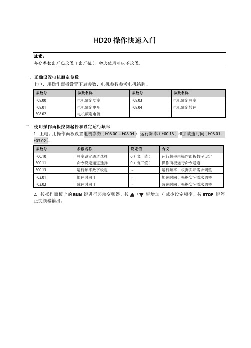
注意: 部分参数出厂已设置(出厂值),初次使用可以不设置。
一、正确设置电机额定参数 上电,用操作面板设置下表参数,电机参数参考电机铭牌。
参数号
参数名称
参数号
F08.00 F08.01 F08.02
电机额定功率 电机额定电压 电机额定电流
F08.03 F08.04
参数名称 电机额定频率 电机额定转速
3.通过调整 AI1 模拟量输入来设定运行频率。
4.合上接线图中的 K1 时,电机正转运行;断开 K1 时,电机停止运行。合上 K2 时,电机反转运行; 断开 K2 时,电机停止运行。K1、K2 同时闭合或断开时电机都停止运行。
五、使用端子控制起停和通讯设定运行频率 1.端子 DI1 为正转信号输入,DI2 为反转信号输入,接线如下图。
二、使用操作面板控制起停和设定运行频率 1.上电。用操作面板设置电机参数(F08.00-F08.04)、运行频率(F00.13)和加减速时间(F03.01、 F03.02)。
参数号
参数名称
设定值
含义
F00.10 F00.11 F00.13 F03.01 F03.02
频率设定通道选择 命令设定通道选择 运行频率数字设定 加速时间 1 减速时间 1
3.合上接线图中的 K1 时,电机正转运行;断开 K1 时,电机停止运行。合上 K2 时,电机反转运行; 断开 K2 时,电机停止运行。K1、K2 同时闭合或断开时电机都停止运行。
4.通过 SCI 通讯(功能代码 0x06)写寄存器 0x3201 来修改运行频率。 如:修改本机地址为 2 的从机运行频率为 45.00Hz,见下表。
参数号
参数名称
设定值
F00.10 F00.11 F03.01 F03.02 F17.00 F17.01 F17.02
迪伯音频工具箱 D20 插头微调器说明书
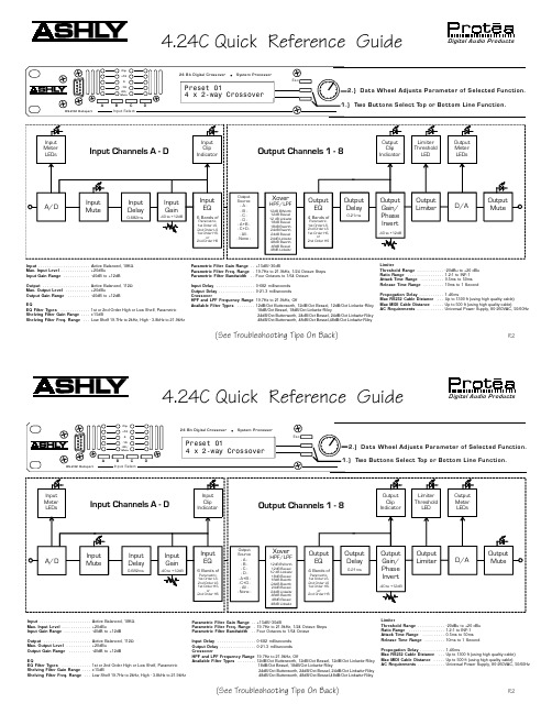
(See Troubleshooting Tips On Back)4.24C Quick Reference GuideInput . . . . . . . . . . . . . . . . . . . . . . .Active Balanced, 18K ΩMax. Input Level . . . . . . . . . . . . .+20dBuInput Gain Range . . . . . . . . . . . .-40dB to +12dB Output . . . . . . . . . . . . . . . . . . . . .Active Balanced, 112ΩMax. Output Level . . . . . . . . . . .+20dBuOutput Gain Range . . . . . . . . . .-40dB to +12dBEQEQ Filter Types . . . . . . . . . . . . .1st or 2nd Order High or Low Shelf, Parametric Shelving Filter Gain Range . . . .±15dBShelving Filter Freq. Range . . .Low Shelf 19.7Hz to 2kHz, High - 3.8kHz to 21.9kHzParametric Filter Gain Range . .+15dB/-30dBParametric Filter Freq. Range .19.7Hz to 21.9kHz, 1/24 Octave Steps Parametric Filter Bandwidth . .Four Octaves to 1/64 OctaveInput Delay . . . . . . . . . . . . . . . . .0-682 milliseconds Output Delay . . . . . . . . . . . . . . . .0-21.3 milliseconds CrossoverHPF and LPF Frequency Range 19.7Hz to 21.9kHz, OffAvailable Filter Types . . . . . . . .12dB/Oct Butterworth, 12dB/Oct Bessel, 12dB/Oct Linkwitz-Riley 18dB/Oct Bessel, 18dB/Oct Linkwitz-Riley24dB/Oct Butterworth, 24dB/Oct Bessel, 24dB/Oct Linkwitz-Riley 48dB/Oct Butterworth, 48dB/Oct Bessel,48dB/Oct Linkwitz-RileyLimiterThreshold Range . . . . . . . . . . . .-20dBu to +20 dBu Ratio Range . . . . . . . . . . . . . . . .1.2:1 to INF:1Attack Time Range . . . . . . . . . .0.5ms to 50ms Release Time Range . . . . . . . . .10ms to 1 SecondPropogation Delay . . . . . . . . . . .1.46msMax RS232 Cable Distance . . .Up to 1300 ft (using high qualtiy cable)Max MIDI Cable Distance . . . . .Up to 500 ft (using high quality cable)AC Requirements . . . . . . . . . . . .Universal Power Supply, 80-260VAC, 50/60Hz(See Troubleshooting Tips On Back)4.24C Quick Reference GuideInput . . . . . . . . . . . . . . . . . . . . . . .Active Balanced, 18K ΩMax. Input Level . . . . . . . . . . . . .+20dBuInput Gain Range . . . . . . . . . . . .-40dB to +12dB Output . . . . . . . . . . . . . . . . . . . . .Active Balanced, 112ΩMax. Output Level . . . . . . . . . . .+20dBuOutput Gain Range . . . . . . . . . .-40dB to +12dBEQEQ Filter Types . . . . . . . . . . . . .1st or 2nd Order High or Low Shelf, Parametric Shelving Filter Gain Range . . . .±15dBShelving Filter Freq. Range . . .Low Shelf 19.7Hz to 2kHz, High - 3.8kHz to 21.9kHzParametric Filter Gain Range . .+15dB/-30dBParametric Filter Freq. Range .19.7Hz to 21.9kHz, 1/24 Octave Steps Parametric Filter Bandwidth . .Four Octaves to 1/64 OctaveInput Delay . . . . . . . . . . . . . . . . .0-682 milliseconds Output Delay . . . . . . . . . . . . . . . .0-21.3 milliseconds CrossoverHPF and LPF Frequency Range 19.7Hz to 21.9kHz, OffAvailable Filter Types . . . . . . . .12dB/Oct Butterworth, 12dB/Oct Bessel, 12dB/Oct Linkwitz-Riley 18dB/Oct Bessel, 18dB/Oct Linkwitz-Riley24dB/Oct Butterworth, 24dB/Oct Bessel, 24dB/Oct Linkwitz-Riley 48dB/Oct Butterworth, 48dB/Oct Bessel,48dB/Oct Linkwitz-RileyLimiterThreshold Range . . . . . . . . . . . .-20dBu to +20 dBu Ratio Range . . . . . . . . . . . . . . . .1.2:1 to INF:1Attack Time Range . . . . . . . . . .0.5ms to 50ms Release Time Range . . . . . . . . .10ms to 1 SecondPropogation Delay . . . . . . . . . . .1.46msMax RS232 Cable Distance . . .Up to 1300 ft (using high qualtiy cable)Max MIDI Cable Distance . . . . .Up to 500 ft (using high quality cable)AC Requirements . . . . . . . . . . . .Universal Power Supply, 80-260VAC, 50/60HzR2R24.24C TROUBLESHOOTING TIPS7.1 - Audio Troubleshooting TipsNo power - Is the detachable AC cord fully plugged in? Is the rear panel power switch on?Controls don't work - check the Security Level. If set to Full Lockout, then Protea unit is "view only". Change security settings in Util menu.No sound - Check to see if the input or output is muted. Is the input or output Gain turned down? Check the selected audio source(s) for each output, making sure there is signal applied to the designated input(s). If the crossover is used, make sure the high pass filter (HPF) is set to a lower frequency than the low pass filter (LPF).Clip light stays on - Is the input signal level too high? Check to see that the nominal input level is 0dBu, allowing 20dB of input headroom. Are input or output gain settings too high? Check to see if an EQ filter has too much boost.Distorted sound but no Clip LED- Check individual EQ filters to see if there is excessive boost.Muffled sound - If expecting full range audio on an output, make sure the crossover settings are not inadvertently set so as to limit the pass band.Excessive Noise - An input signal level or an input gain setting that is too low could require the loss to be made up for at the output gain stage, producing more noise than a properly set up gain structure. Do not use the 4.24C for dramatic increases in level, but rather optimize the signal source for a nominal 0dBu output.Forgot the password - See section 4.7e of Manual7.2 RS-232/MIDI Troubleshooting Tips1. Test all data cables. Use standard MIDI cables and RS232 data cables with all conductors wired straight through. Monitor cables and Null Modem cables use non-standard wiring schemes, they will not work with a Protea. See section 5.2 and 5.3 if using custom wiring.2. Use a valid PC serial port. You must use a serial port that is not opened to any other application, such as a mouse, modem, or another program. To verify that the port exists look in: Control Panel - System - Device Manager - Ports. While you're there, make sure that the port has no warnings or conflicts. There is no need to change the port settings because Protea System Software will do this automatically. Finally, you must select the valid port in Protea System Software. This is done under the Communi-cations heading - Com Port Assignment.3. Make sure that the RS-232 mode switch, located on the back of4.24C, is in the "out" position. There is just one exception to this rule: the RS-232 mode switch gets pushed in only when both the RS232 Dataport is connected to a PC, and the 4.24C is part of several Protea products in a MIDI chain.4. Make sure the MIDI channel selected within the 4.24C (Util menu) matches the MIDI channel chosen for the crossover section of Protea System Software, and make sure that no other devices use that MIDI channel.4.24C TROUBLESHOOTING TIPS7.1 - Audio Troubleshooting TipsNo power - Is the detachable AC cord fully plugged in? Is the rear panel power switch on?Controls don't work - check the Security Level. If set to Full Lockout, then Protea unit is "view only". Change security settings in Util menu.No sound - Check to see if the input or output is muted. Is the input or output Gain turned down? Check the selected audio source(s) for each output, making sure there is signal applied to the designated input(s). If the crossover is used, make sure the high pass filter (HPF) is set to a lower frequency than the low pass filter (LPF).Clip light stays on - Is the input signal level too high? Check to see that the nominal input level is 0dBu, allowing 20dB of input headroom. Are input or output gain settings too high? Check to see if an EQ filter has too much boost.Distorted sound but no Clip LED- Check individual EQ filters to see if there is excessive boost.Muffled sound - If expecting full range audio on an output, make sure the crossover settings are not inadvertently set so as to limit the pass band.Excessive Noise - An input signal level or an input gain setting that is too low could require the loss to be made up for at the output gain stage, producing more noise than a properly set up gain structure. Do not use the 4.24C for dramatic increases in level, but rather optimize the signal source for a nominal 0dBu output.Forgot the password - See section 4.7e of Manual7.2 RS-232/MIDI Troubleshooting Tips1. Test all data cables. Use standard MIDI cables and RS232 data cables with all conductors wired straight through. Monitor cables and Null Modem cables use non-standard wiring schemes, they will not work with a Protea. See section 5.2 and 5.3 if using custom wiring.2. Use a valid PC serial port. You must use a serial port that is not opened to any other application, such as a mouse, modem, or another program. To verify that the port exists look in: Control Panel - System - Device Manager - Ports. While you're there, make sure that the port has no warnings or conflicts. There is no need to change the port settings because Protea System Software will do this automatically. Finally, you must select the valid port in Protea System Software. This is done under the Communi-cations heading - Com Port Assignment.3. Make sure that the RS-232 mode switch, located on the back of4.24C, is in the "out" position. There is just one exception to this rule: the RS-232 mode switch gets pushed in only when both the RS232 Dataport is connected to a PC, and the 4.24C is part of several Protea products in a MIDI chain.4. Make sure the MIDI channel selected within the 4.24C (Util menu) matches the MIDI channel chosen for the crossover section of Protea System Software, and make sure that no other devices use that MIDI channel.。
Dell Latitude D820 用户指南说明书
Dell™ Latitude™ D820 使用者指南尋找資訊關於您的電腦使用電池使用鍵盤使用多媒體使用顯示幕使用網路使用插卡保護您的電腦故障排除系統設定程式攜帶您的電腦旅行重新安裝軟體新增和更換零件Dell™ QuickSet規格獲得幫助附錄詞彙表單按左側的連結可獲得有關您電腦的功能和作業的資訊。
若要獲得有關電腦隨附的其他說明文件的資訊,請參閱尋找資訊。
註、注意事項和警示縮寫和簡寫用語若要獲得縮寫和簡寫用語的完整清單,請參閱詞彙表。
如果您購買的是 Dell™ n Series 電腦,則本文件中關於 Microsoft ® Windows ® 作業系統的所有參考均不適用。
本文件中的資訊如有更改,恕不另行通知。
© 2006 D e l l I n c.。
版權所有,翻印必究。
未經 Dell Inc. 的書面許可,不得以任何形式進行複製。
本文中使用的商標:D e l l 、D E L L 徽標、I n s p i r o n 、D e l l P r e c i s i o n 、D i m e n s i o n 、O p t i P l e x 、L a t i t u d e 、P o w er E dge 、P o w e r V a u l t 、P o w e r A p p 、ExpressCharge 和 Dell OpenManage 是 Dell Inc. 的商標;I n t e l 和 P e n t i u m 是 Intel Corporation 的註冊商標;M i c r o s o f t 、O u t l o o k 和 W i n d o w s 是 Microsoft Corporation 的註冊商標;E M C 是 EMC Corporation 的註冊商標;能源之星是美國環境保護署的註冊商標。
作為能源之星的一員,Dell Inc. 已確定本產品符合能源之星的能源效率規範。
VISTA-20中文说明书
后备电池 ....................................................................................................................... ................ 11 地线 ......................................................................................................................................... .......11 基本(硬线)防区 ................................................................................................................ ........... 12
VISTA-20P
报警控制通信主机
安装使用手册
1
目录
功能及其安装部分 ................................................................................... .......... . ............ 5
SIMADYN D数字控制系统接口模块 SE47.1用户手册说明书

SIMADYN DUser Manual Digital Control SystemInterface module SE47.1Edition 05.95DK-Nr. 283341User Manual, Interface module SE47.1Edition Edition status 1Interface module SE47.104.91 2Interface module SE47.105.95Copying of this document and giving it to others and the use orcommunication of the contents thereof is forbidden without expressauthority. Offenders are liable to the payment of damages. All rightsare reserved in the event of the grant of a patent or the registration ofa utility model or design.We have checked the contents of this Manual to ensure that theycoincide with the described hardware and software. However,deviations cannot be completely ruled-out, so we cannot guaranteecomplete conformance. However, the information in this document isregularly checked and the necessary corrections included insubsequent editions. We are thankful for any recommendations orsuggestions.ContentsContentsWarning information (1)1. Description (3)2. Design (3)3. Application Notes (3)4. Technical Specification (4)5. Plug Connector Allocation (5)5.1. Allocation of the 25 pin SUB D socket strip X1 (5)5.2. Allocation of the 9 pin SUB D socket strips X2,X3 (5)6. Terms/Abbreviations (5)7. Literature (5)8. Appendices (6)9. ECB instructions (7)Siemens AG Dk-Nr. 283341Edition 05.95SIMADYN D Hardware User ManualWarning informationEdition 05.95Siemens AG Dk-Nr. 283341SIMADYN D Hardware User ManualWarning informationN O T E !The information in this Manual does not purport to cover all details or variations in equipment, nor to provide for every possible contingency to be met in connection with installation, operation or maintenance.Should further information be desired or should particular problems arise which are not covered sufficiently for the purchaser’s purposes, please contact your local Siemens office.Further, the contents of this Manual shall not become a part of or modify any prior or existing agreement, committment or relationship. The sales contract contains the entire obligation of Siemens. The warranty contained in the contract between the parties is the sole warranty of Siemens. Any statements contained herein do not create new warranties nor modify the existing warranty.Warning informationSiemens AG Dk-Nr. 283341Edition 05.951 SIMADYN D Hardware User ManualWarning information2Edition 05.95Siemens AG Dk-Nr. 283341SIMADYN D Hardware User ManualDefinitions*QUALIFIED PERSONNELFor the purpose of this User Manual and product labels, a …Qualified person“ is someone who is familiar with the installation, mounting, start-up and operation of the equipment and the hazards involved. He or she must have the following qualifications:1.Trained and authorized to energize, de-energize, clear, ground a nd tag circuits and equipment in accordance with established safety procedures.2.Trained in the proper care and use of protective equipment in accordance with established safety procedures.3.Trained in rendering first aid.*DANGERFor the purpose of this User Manual and product labels, …Danger“ indicates death, severe personal injury and/or substantial property damage will result if proper precautions are not taken.*WARNINGFor the purpose of this User Manual and product labels, …Warning“ indicates death, severe personal injury or property damage can result if proper precautions are not taken.*CAUTIONFor the purpose of this User Manual and product labels, …Caution“ indicates that minor personal injury or material damage can result if proper precautions are not taken.*NOTEFor the purpose of this User Manual, …Note“ indicates information about the product or the respective part of the User Manual which is essential to highlight.W A R N I N G !Hazardous voltages are present in this electrical equipment during operation.Non-observance of the safety instructions can result in severe personal injury or property damage.It is especially important that the warning information in all of the relevant Operating Instructions are strictly observed.DescriptionSiemens AG Dk-Nr. 283341Edition 05.953SIMADYN D Hardware User Manual1. DescriptionThe bus interface module (BIM) SE 47.1 order no. : 6DD1681-0EH1 is an interface module designed for the communication of DUST 4 in the SIMADYN D control system.BIM FUNCTION1. A Manchester Encoder/Decoder MED implements :a) the synchronization, i.e. generating the data transfer clockb) the conversion of the SCC data format, NRZ code, in manchester code and back.2. The RTS signal, software controlled, switches the bus accessing.3. The interface IC's, designed to RS485 specification, convert the MED input/output signals to thesignal format of the transmission path.4. A counter, triggered by an encoder clock, monitors the telegram length.Each BIM is connected to a DUST 4 partner via a plug connector cable, in which the data, the control signals and 5V power supply are transmitted. The transfer path consists of bus cables and plug connectors with which the BIM's are inter-connected. The first and last BIM in the system are terminated with a plug containing a terminating resistance.2. Design* Casing (support element), snap-on rail mounting * Metal cover as fault protection * Screen connection - M3 threaded bolts * SUB-D - socket strips- 25 pin, for the plug connection to the processor board. - 2x9 pin, for the plug connection to the serial bus. * Indicators , LED's : - red ( receive ) - green ( transmit )* HF-Transformers for voltage isolation between SIMADYN D and the transfer path3. Application NotesTo be used:for the partner: Interface SS3:RS485order no.6DD1688-1AC0as connection from BIM to the partner: cable SC27:RS485order no.6DD1684-0CH0for the serial bus : 1. Parts sets SUB-D 9pin SM5:pins order no.6DD1680-0AF0 2. Terminating plug SM6order no.6DD1680-0AG0 3. cable Data , limit values |Example *)External diameter Screen Conductors Conductor diameter Wave impedance 8mm, maximum (because of casing)total screen 1 twisted pair0,8mm, maximum (solder connection)100.....150 Ohm6,6mmtotal screen 2 twisted pairs 0,32mm [AWG 28]120 OhmTechnical Specification*)low loss cable for EIA RS485 applications, BELDEN ELECTRONICS, cable no. 81324. Technical SpecificationINSULATION GROUP acc. VDE 0110 / 1.89 for contamination grade 2AMBIENT TEMPERATURE0 to 55 deg. CSTORAGE TEMPERATURE-40 to 70 deg. CHUMIDITY CLASS F acc. DIN 40040PROTECTION TYPE IP00 acc. DIN 40050MECHANICAL STRESS acc. SN 29010 class 12PACKAGING SYSTEM snap-on rail mountingDIMENSIONS135 x 77 x 58.5 (mm)WEIGHT165 gr.ELECTRICAL DATA min. typ. max.SUPPLY- VOLTAGE DC (Uv) : 4,75 V 5 V 5,75 V- CURRENT250 mAINPUTS- VOLTAGE- 7 + 12 V- SENSITIVITY± 200 mV- HYSTERESIS50 mV- RESISTANCE12 KOUTPUTS- VOLTAGE with load± 1,5 V without load ± Uv- RESISTANCE 54 R- SHORT CIRCUIT CURRENT 500mADATA RATE *) 1 MBit/sTOTAL LENGTH OF THE BUS CABLE *) 200 mNUMBER OF PARTNERS 32*)/1/ Guide lines for the selection of cables are available in section A2./2/ shows in section 9.2 typical values for the cable lengths dependent upon the transmission speed (example : telephone cable).4Edition 05.95Siemens AG Dk-Nr. 283341SIMADYN D Hardware User ManualPlug Connector Allocation 5. Plug Connector Allocation5.1. Allocation of the 25 pin SUB D socket strip X1Pin Designation Pin Designation1NC not connected14*RTS (-)2*RTS (+)15*TRxC(-) Transmit/Receive Clock3*TRxC(+) Transmit/Receive Clock16NC4NC17TxD (-) Transmit Data5TxD (+) Transmit Data18M Ground6*RTxC(+) Receive/Transmit Clock19*RTxC(-) Receive/Transmit Clock7*DCD (+) Data Carrier Detect20*DCD (-) Data Carrier Detect8RxD (+) Receive Data21RxD (-) Receive Data9M Ground22P5 Supply 5 V10NC23P5 Supply 5 V11NC24NC12NC25NC13NC5.2. Allocation of the 9 pin SUB D socket strips X2,X3Pin Designation Pin Designation1Signal A (Pin 1 & 2 connected)6Signal B (Pin 6 & 7 connected)2Signal A7Signal B3 5 V (via resistance 1k2)8Ground (via resistance 1k2)4NC9Screen5Screen6. Terms/AbbreviationsBIM Bus interface moduleDUST Data transmission controlMED Manchester Encoder and DecoderNRZ Non Return to ZeroSCC Serial Communication ControllerPartner on the communication participating processor board7. Literature/1/ EIA RS485 Version: April 83Electrical Characteristics of Generators and Receiversof use in Balanced Digital Multipoint Systems/2/ DIN 66 259 Teil 3: Maerz 1983Elektrische Eigenschaften der SchnittstellenleitungenDoppelstrom, symmetrisch, bis 10 Mbit/sSiemens AG Dk-Nr. 283341Edition 05.955 SIMADYN D Hardware User ManualAppendices6Edition 05.95Siemens AG Dk-Nr. 283341SIMADYN D Hardware User Manual8. AppendicesApplication notesAppendix 1Partner 1Partner 2Partner nPartner zProcessor module :voltage equalizing Overview block diagram3GE 465 681 9047.10 SU Dimension Drawing & Connector Allocation table3GE 465 681 9047.10 MBECB instructions 9. ECB instructionsComponents which can be destroyed by electrostatic discharge (ECB)Generally, electronic boards should only be touched when absolutely necessary.The human body must be electrically discharged before touching an electronic board. This can be simply done by touching a conductive, grounded object directly beforehand (e.g. bare metal cubicle components, socket outlet protective conductor contact.Boards must not come into contact with highly-insulating materials - e.g. plastic foils, insulated desktops, articles of clothing manufactured from man-made fibers.Boards must only be placed on conductive surfaces.When soldering, the soldering iron tip must be grounded.Boards and components should only be stored and transported in conductive packaging (e.g. metalized plastic boxes, metal containers).If the packing material is not conductive, the boards must be wrapped with a conductive packing material, e.g. conductive foam rubber or household aluminum foil.The necessary ECB protective measures are clearly shown in the following diagram.a = Conductive floor surface d = ECB overallb = ECB table e = ECB chainc = ECB shoes f = Cubicle ground connectionSiemens AG Dk-Nr. 283341Edition 05.957 SIMADYN D Hardware User ManualECB instructions8Edition 05.95Siemens AG Dk-Nr. 283341SIMADYN D Hardware User ManualECB instructionsSiemens AG Dk-Nr. 283341Edition 05.959SIMADYN D Hardware User Manual Drives and Standard ProductsMotors and Drives Systems GroupPostfach 3269, D-91050 Erlangen System-Based Technology。
新D型模块机操作用户手册_邦普-服务版_标准20RT30RT40RT

品号:20010040036 版号:KMS1106-A0模块式风冷冷热水机组KMS015D(R)(2)(H)-10~KMS360D(R)(2)(H)-0C安装使用本机组之前,请认真阅读本说明书,并妥善保管附录2 状态号码列表附录3 机器参数设置494847附录1 故障代码查询44231911432目 录前言 安全注意事项 第一章 机组外观尺寸及电路图 第二章 机组的搬运及安装 第三章 水系统调试、试运转及日常维护保养 第四章 机组操作 第五章 故障分析及处理前言1. 尊敬的客户,感谢您选用国祥空调产品,本公司产品均经严格的品质管理及性能测试合格后方可出厂,请您放心使用。
2. 产品保修期内,任何因产品质量问题造成机组故障,经本公司认定后,我们将提供免费周到的服务。
3. 如因搬运、天灾、战争等不可控制的因素,或未按本使用手册操作保养或经非本公司人员擅自修理、改造所引起的故障和缺陷,将不列入产品保修范围之内。
4. 产品保修期为:产品试车运转后12个月或产品交货后18个月,以先到期者为准。
5. 本公司拥有对本手册的最终解释权。
安全注意事项机组搬运、安装、调试及使用过程中,请用户务必遵守以下安全注意事项,以免对机组或人体造成不必要损害。
若因未能遵守以下安全注意事项而造成机组故障或人体伤害,本公司概不负任何责任。
1. 机组吊装前请确认机组底座上用于起吊的吊耳紧固螺栓无松动。
2. 机组吊装时应注意周围人员的安全,注意防止机组倾斜而沿吊索滑脱。
3. 机组搬运、安装和操作期间,不得损害机组配件或对机组进行人为拆装或破坏。
4. 空调水系统必须由具备相应资质的专业安装人员严格按水系统图安装,且对于多模块机组水路需按同程配管,以保证各模块水系统阻力和流量平衡,必要时应配置流量平衡阀。
5. 请由专业电工严格按电工法规及本公司电气装置要求对机组电源进线和机组接地保护进行施工。
6. 机组运转时严禁用手触摸电气元件、电源配线、压缩机及其它运转部件,以免造成人体伤害。
长虹LED39D20液晶彩电维修手册

1.2 维护保养注意事项
清洁—清洁本机前,请关闭电源。用微湿的软棉布轻轻擦拭。在液晶屏幕未晾干前不能接通本机电源。另 外切勿让机壳长时间接触橡胶等物品。对于不易擦掉的污垢,可用棉布蘸经过稀释的中性洗剂( 如 餐具洗涤剂) 后拧干擦拭。切勿使用液态或喷雾式清洁剂及有机溶剂来清洁电视机。 请定期清洁交流电源插头。不要用潮湿的手触摸液晶电视机,以免导致触电或将其损坏。 附件—请使用本机配有的相关附件和制造商推荐的附件。使用不合适的附件可能会导致意外。 像素疵点—液晶屏是尖端科技产品,可显示精细的图像。偶尔会有极少数的固定像素长亮,此乃液晶屏的 结构特性,并非故障,不会影响您的使用。
5
3.2 控制面板
说明: 下列示图只是方便你认识各个端子所在位置,并方便连接外部设备,由于产品的改进,可能与实际的标示 不一致,请以实物为准。 机前
注意:整机后壳所贴机号标签是产品的唯一身份标识。 音量+/- -- 增大/ 减小音量 频道 ▲ / ▼ -- 更改节目频道 信号源 -- 打开节目源菜单,可在电视、视频、分量信号、HDMI、电脑、USB 之间切换 菜单 -- 打开/ 关闭菜单 电源 -- 待机/ 开机键 遥控接收窗-- 接收遥控器的信号 电源指示灯-- 在待机状态下,显示指示灯亮红灯; 在开机状态下,显示指示灯亮蓝灯
按钮 电源 静音 TV/AV 回看 P+/P﹣/v﹣/v+ 菜单 0-9 演示
说明 暂时关闭电视机或将电视机从待机模 式打开 打开/关闭电视机声音 显示信号源列表 在当前频道或信源和上一个选择的频 道或信源之间快捷切换 方向键,切换频道,调节音量 显示/关闭TV主菜单 数字选择键,其可选范围为1~200 快捷选择您想要的图像模式 无作用 无作用 无作用 无作用 多媒体上一曲功能:USB状态下按键 多媒体下一曲功能:USB状态下按键 无作用 退出功能 播放/暂停功能:USB状态下按键 无作用 停止多媒体播放功能: USB 状态下按 键 无作用 确认操作 快捷选择您想要的画面格式
戴尔 Latitude D520 快速参考指南说明书

Dell™ Latitude™ D520 Quick Reference GuideModel PP17Lw w w.d e l l.c o m|s u p p o r t.d e l l.c o mNotes, Notices, and CautionsNOTE: A NOTE indicates important information that helps you make better use of your computer.NOTICE: A NOTICE indicates either potential damage to hardware or loss of data and tells you how to avoid theproblem.CAUTION: A CAUTION indicates a potential for property damage, personal injury, or death. Abbreviations and AcronymsFor a complete list of abbreviations and acronyms, see the Glossary in your User’s Guide.If you purchased a Dell™ n Series computer, any references in this document to Microsoft® Windows®operating systems are not applicable.NOTE: Some features or media may be optional and may not ship with your computer. Some features or media may not be available in certain countries.____________________Information in this document is subject to change without notice.©2006Dell Inc.All rights reserved.Reproduction in any manner whatsoever without the written permission of Dell Inc.is strictly forbidden.Trademarks used in this text: Dell, the DELL logo, Latitude, and ExpressCharge are trademarks of Dell Inc.; Intel is a registered trademark of Intel Corporation; Microsoft, Outlook, and Windows are registered trademarks of Microsoft Corporation.Other trademarks and trade names may be used in this document to refer to either the entities claiming the marks and names or their products. Dell Inc. disclaims any proprietary interest in trademarks and trade names other than its own.Model PP17LFebruary 2006P/N MF178Rev. A00ContentsFinding Information (5)Setting Up Your Computer (9)About Your Computer (10)Front View (10)Left Side View (11)Right Side View (11)Back View (11)Bottom View (12)Using a Battery (13)Battery Performance (13)Checking the Battery Charge (14)Charging the Battery (15)Removing the Battery (15)Storing a Battery (16)Troubleshooting (17)Lockups and Software Problems (17)Dell Diagnostics (18)Index (23)Contents34ContentsFinding InformationNOTE: Some features or media may be optional and may not ship with your computer. Some features or media may not be available in certain countries.NOTE: Additional information may ship with your computer.What Are You Looking For?Find It Here•A diagnostic program for my computer •Drivers for my computer•My device documentation •Notebook System Software (NSS)Drivers and Utilities CD (also known as ResourceCD) NOTE: The Drivers and Utilities CD may be optional and may not ship with your computer.Documentation and drivers are already installed on your computer. Y ou can use the CD to reinstall drivers (see "Reinstalling Drivers and Utilities" in your User’s Guide) or to run the Dell Diagnostics (see "Dell Diagnostics" on page18).Readme files may beincluded on your CD toprovide last-minuteupdates about technicalchanges to your computeror advanced technical-reference material fortechnicians or experiencedusers.NOTE: Drivers and documentation updates can be found at .•Warranty information•Terms and Conditions (U.S. only)•Safety instructions •Regulatory information•Ergonomics information •End User License AgreementDell™ Product Information GuideQuick Reference Guide5•How to remove and replace parts •Specifications•How to configure system settings •How to troubleshoot and solve problems Dell Latitude™ User’s GuideMicrosoft Windows XP Help and Support Center1Click Start→Help and Support→ Dell User and System Guides→System Guides.2Click the User’s Guide for your computer.•Service Tag and Express Service Code •Microsoft Windows License Label Service Tag and Microsoft® Windows® LicenseThese labels are located on your computer.•Use the Service Tag to identify your computer when you use or contact support.•Enter the ExpressService Code to directyour call whencontacting support.What Are You Looking For?Find It Here6Quick Reference Guide•Solutions — Troubleshooting hints and tips, articles from technicians, online courses, and frequently asked questions•Community — Online discussion with other Dell customers•Upgrades — Upgrade information for components, such as memory, the hard drive, and the operating system •Customer Care — Contact information, service call and order status, warranty, and repair information •Service and support — Service call status and support history, service contract, online discussions with technical support•Reference — Computer documentation, details on my computer configuration, product specifications, and white papers•Downloads — Certified drivers, patches, and software updates•Notebook System Software (NSS)— If you reinstall the operating system for your computer, you should also reinstall the NSS utility. NSS provides critical updates for your operating system and support for Dell™3.5-inch USB floppy drives, Intel® processors, optical drives, and USB devices. NSS is necessary for correct operation of your Dell computer. The software automatically detects your computer and operating system and installs the updates appropriate for your configuration.Dell Support Website — NOTE: Select your region or business segment to view the appropriate support site.To download Notebook System Software:1Go to , select your region or business segment, and enter your Service Tag.2Select Drivers & Downloads and click Go.3Click your operating system and search for the keyword Notebook System Software.NOTE: The user interface may vary depending on your selections.•Software upgrades and troubleshooting hints — Frequently asked questions, hot topics, and general health of your computing environment Dell Support UtilityThe Dell Support Utility is an automated upgrade and notification system installed on your computer. This support provides real-time health scans of your computing environment, software updates, and relevant self-support information. Access the Dell Support Utility from the icon in the taskbar. For more information, see "Dell Support Utility" in your User’s Guide.•How to use Windows XP•How to work with programs and files •How to personalize my desktop Windows Help and Support Center1Click Start→Help and Support.2T ype a word or phrase that describes your problem and click the arrow icon.3Click the topic that describes your problem.4Follow the instructions on the screen.What Are You Looking For?Find It HereQuick Reference Guide7•Information on network activity, the Power Management Wizard, hotkeys, and other items controlled by Dell QuickSet.Dell QuickSet HelpTo view Dell QuickSet Help, right-click the icon in the Microsoft®Windows® taskbar.For more information on Dell QuickSet, see "Dell™ QuickSet" in your User’s Guide.•How to reinstall my operating system Operating System CDNOTE: The Operating System CD may be optional and maynot ship with your computer.The operating system is already installed on your computer.To reinstall your operating system, use the OperatingSystem CD. See "Reinstalling Microsoft® Windows® XP"in your User’s Guide.After you reinstall youroperating system, use theoptional Drivers andUtilities CD (ResourceCD)to reinstall drivers for thedevices that came withyour computer.Y our operating systemproduct key label is locatedon your computer.NOTE: The color of your CD varies based on the operatingsystem you ordered.What Are You Looking For?Find It Here8Quick Reference GuideQuick Reference Guide 9Setting Up Your ComputerCAUTION: Before you begin any of the procedures in this section, follow the safety instructions in theProduct Information Guide .1Unpack the accessories box.2Set aside the contents of the accessories box, which you will need to complete the setup of your computer.The accessories box also contains user documentation and any software or additional hardware (such as PC Cards, drives, or batteries) that you have ordered.3Connect the AC adapter to the AC adapter connector on the computer and to the electrical outlet.4Open the computer display and press the power button to turn on the computer (see "Front View" on page 10).NOTE: It is recommended that you turn on and shut down your computer at least once before you install any cards or connect the computer to a docking device or other external device, such as a printer.10Quick Reference GuideAbout Your ComputerFront View1display 2device status lights 3keyboard 4touch pad 5display latch 6speakers 7touch pad buttons8keyboard status lights9power button413872695Left Side ViewRight Side ViewBack ViewCAUTION: Do not block, push objects into, or allow dust to accumulate in the air vents. Do not store your computer in a low-airflow environment, such as a closed briefcase, while it is running. Restricting the airflow can damage the computer or cause a fire.1security cable slot 2IEEE 1394 connector 3PC Card/ExpressCard slot 4infrared sensor 5audio connectors (2)6hard drive 1media bay 2device latch release 3USB connectors (2)352416123Bottom View1USB connectors (2)2modem connector (RJ-11)3network connector (RJ-45)4S-video TV-out connector 5serial connector 6video connector7AC adapter connector 8air vents 1memory module/modem/WLAN Mini-Card/coin-cell battery cover 2battery-bay latch release 3battery charge gauge 4battery 5docking device slot 6air vents 7hard drive 812345671542736Using a BatteryBattery PerformanceNOTE: For information about the Dell warranty for your computer, see the Product Information Guide or separate paper warranty document that shipped with your computer.For optimal computer performance and to help preserve BIOS settings, operate your Dell™ portable computer with the main battery installed at all times. One battery is supplied as standard equipment in the battery bay.NOTE: Because the battery may not be fully charged, use the AC adapter to connect your new computer to an electrical outlet the first time you use the computer. For best results, operate the computer with the AC adapter until the battery is fully charged. To view battery charge status, click Start→ Settings→ Control Panel→ Power Options→Power Meter.NOTE: Battery operating time (the time the battery can hold a charge) decreases over time. Depending on how often the battery is used and the conditions under which it is used, you may need to purchase a new battery during the life of your computer.Battery operating time varies depending on operating conditions. Y ou can install an optional second battery in the media bay to significantly increase operating time.Operating time is significantly reduced when you perform operations including, but not limited to, the following:•Using optical drives•Using wireless communications devices, PC Cards, ExpressCards, media memory cards, or USB devices•Using high-brightness display settings, 3D screen savers, or other power-intensive programs such as complex 3D graphics applications•Running the computer in maximum performance mode (see "Configuring Power Management Settings" in your User’s Guide).NOTE: It is recommended that you connect your computer to an electrical outlet when writing to a CD or DVD.Y ou can check the battery charge before you insert the battery into the computer (see "Checking the Battery Charge" on page14). Y ou can also set power management options to alert you when the battery charge is low (see "Configuring Power Management Settings" in your User’s Guide).CAUTION: Using an incompatible battery may increase the risk of fire or explosion. Replace the battery only with a compatible battery purchased from Dell. The lithium-ion battery is designed to work with your Dellcomputer. Do not use a battery from other computers with your computer.CAUTION: Do not dispose of batteries with household waste. When your battery no longer holds a charge, call your local waste disposal or environmental agency for advice on disposing of a lithium-ion battery. See "Battery Disposal" in the Product Information Guide.CAUTION: Misuse of the battery may increase the risk of fire or chemical burn. Do not puncture, incinerate, disassemble, or expose the battery to temperatures above 60°C (140°F). Keep the battery away from children.Handle damaged or leaking batteries with extreme care. Damaged batteries may leak and cause personal injury or equipment damage.Checking the Battery ChargeThe Dell QuickSet Battery Meter, the Microsoft Windows Power Meter window and icon, the battery charge gauge and health gauge, and the low-battery warning provide information on the battery charge.Dell™ QuickSet Battery MeterIf Dell QuickSet is installed, press <Fn><F3> to display the QuickSet Battery Meter. The Battery Meter displays status, battery health, charge level, and charge completion time for the battery in your computer.For more information about QuickSet, right-click the icon in the taskbar, and click Help.Microsoft® Windows® Power MeterThe Windows Power Meter indicates the remaining battery charge. To check the Power Meter, double-click the icon on the taskbar.If the computer is connected to an electrical outlet, a icon appears.Charge GaugeBy either pressing once or pressing and holding the status button on the charge gauge on the battery, you can check:•Battery charge (check by pressing and releasing the status button)•Battery health (check by pressing and holding the status button)The battery operating time is largely determined by the number of times it is charged. After hundreds of charge and discharge cycles, batteries lose some charge capacity—or battery health. That is, a battery can show a status of "charged" but maintain a reduced charge capacity (health).Check the Battery ChargeTo check the battery charge, press and release the status button on the battery charge gauge to illuminate the charge-level lights. Each light represents approximately 20 percent of the total battery charge. For example, if the battery has 80 percent of its charge remaining, four of the lights are on. If no lights appear, the battery has no charge.Check the Battery HealthNOTE: You can check battery health in one of two ways: by using the charge gauge on the battery as described below and by using the Battery Meter in Dell QuickSet. For information about QuickSet, right-click the icon in the taskbar, and click Help.To check the battery health using the charge gauge, press and hold the status button on the battery charge gauge for at least 3seconds. If no lights appear, the battery is in good condition, and more than 80percent of its original charge capacity remains. Each light represents incremental degradation. If five lights appear, less than 60percent of the charge capacity remains, and you should consider replacing the battery. See "Specifications" in your User’s Guide for more information about the battery operating time. Low-Battery WarningNOTICE: To avoid losing or corrupting data, save your work immediately after a low-battery warning. Thenconnect the computer to an electrical outlet. If the battery runs completely out of power, hibernate mode begins automatically.By default, a pop-up window warns you when the battery charge is approximately 90 percent depleted. Y ou can change the settings for the battery alarms in QuickSet or the Power Options Properties window. See "Configuring Power Management Settings" in your User’s Guide for information about accessing QuickSet or the Power Options Properties window.Charging the BatteryNOTE: With Dell™ ExpressCharge™, when the computer is turned off, the AC adapter charges a completely discharged battery to 80 percent in about 1 hour and to 100 percent in approximately 2 hours. Charge time is longer with the computer turned on. You can leave the battery in the computer for as long as you like. The battery’s internal circuitry prevents the battery from overcharging.When you connect the computer to an electrical outlet or install a battery while the computer is connected to an electrical outlet, the computer checks the battery charge and temperature. If necessary, the AC adapter then charges the battery and maintains the battery charge.If the battery is hot from being used in your computer or being in a hot environment, the battery may not charge when you connect the computer to an electrical outlet.The battery is too hot to start charging if the light flashes alternately green and orange. Disconnect the computer from the electrical outlet and allow the computer and the battery to cool to room temperature. Then connect the computer to an electrical outlet to continue charging the battery.For more information about resolving problems with a battery, see "Power Problems" in your User’s Guide.Removing the BatteryCAUTION: Before performing these procedures, turn off the computer, disconnect the AC adapter from the electrical outlet and the computer, disconnect the modem from the wall connector and computer, and remove any other external cables from the computer.CAUTION: Using an incompatible battery may increase the risk of fire or explosion. Replace the battery only with a compatible battery purchased from Dell. The battery is designed to work with your Dell™ computer. Do not use a battery from other computers with your computer.NOTICE: You must remove all external cables from the computer to avoid possible connector damage.For information about replacing the second battery, which is located in the media bay, see "Using Multimedia" in yourUser’s Guide .To remove the battery:1If the computer is connected to a docking device (docked), undock it. See the documentation thatcame with your docking device for instructions.2Ensure that the computer is turned off.3Slide and hold the battery-bay latch release on the bottom of the computer.4Lift the battery out of the battery bay.To replace the battery, place the battery in the bay and press down until the battery-bay latch release clicks.Storing a BatteryRemove the battery when you store your computer for an extended period of time. A battery discharges during prolonged storage. After a long storage period, recharge the battery fully before you use it (see "Charging the Battery" on page 15).1battery-bay latch release 2battery12TroubleshootingLockups and Software ProblemsCAUTION: Before you begin any of the procedures in this section, follow the safety instructions in the Product Information Guide.The computer does not start upE N S U R E T H A T T H E AC A D A P T E R I SF I R M L Y C O N N E C T E D T O T H E C O M P U T E R A N D T O T H E E L E C T R I C A L O U T L E T. The computer stops respondingNOTICE: You might lose data if you are unable to perform an operating system shutdown.T U R N T H E C O M P U T E R O F F—If you are unable to get a response by pressing a key on your keyboard or moving your mouse, press and hold the power button for at least 8 to 10 seconds until the computer turns off. Then restart your computer.A program stops responding or crashes repeatedlyNOTE: Software usually includes installation instructions in its documentation or on a floppy disk or CD.E N D T H E P R O G R A M—1Press <Ctrl><Shift><Esc> simultaneously.2Click Task Manager.3Click the program that is no longer responding.4Click End Task.C H E C K T H E S O F T W A R ED O C U ME N T A T I O N—If necessary, uninstall and then reinstall the program.A program is designed for an earlier Microsoft® Windows® operating systemR U N T H E P R O G R A M C O M P A T I B I L I T Y W I Z A R D—The Program Compatibility Wizard configures a program so that it runs in an environment similar to non-Windows XP operating system environments.1Click Start→All Programs→ Accessories→Program Compatibility Wizard→ Next.2Follow the instructions on the screen.A solid blue screen appearsT U R N T H E C O M P U T E R O F F—If you are unable to get a response by pressing a key on your keyboard or moving your mouse, press and hold the power button for at least 8 to 10 seconds until the computer turns off. Then restart your computer.Other software problemsC H E C K T H E S O F T W A R ED O C U ME N T A T I O N O R C O N T A C T T H E S OF T W A R E M A N U F A C T U R E R F O R T R O U B L E S H O O T I NG I N F O R M A T I O N—•Ensure that the program is compatible with the operating system installed on your computer.•Ensure that your computer meets the minimum hardware requirements needed to run the software.See the software documentation for information.•Ensure that the program is installed and configured properly.•Verify that the device drivers do not conflict with the program.•If necessary, uninstall and then reinstall the program.B AC K U P Y O U R F I L E S I M M ED I A TE L Y.U S E A V I R U S-S C A N N I N G P R O G R A M T O C H E C K T H E H A R D D R I V E, F L O P P Y D I S K S, O R CD S.S A V E A N D C L O S E A N Y O P E N F I L E S O R P R O G R A M S A N D S H U T D O W N Y O U R C O M P U T E R T H R O U G H T H E Start M E N U. S C A N T H E C O M P U T E R F O R S P Y W A R E—If you are experiencing slow computer performance, you frequently receive pop-up advertisements, or you are having problems connecting to the Internet, your computer might be infected with spyware. Use an anti-virus program that includes anti-spyware protection (your program may require an upgrade) to scan the computer and remove spyware. For more information, go to and search for the keyword spyware.R U N T H E D E L L D I A G N O S T I C S—See "Dell Diagnostics" on page18. If all tests run successfully, the error condition is related to a software problem.Dell DiagnosticsCAUTION: Before you begin any of the procedures in this section, follow the safety instructions in the Product Information Guide.When to Use the Dell DiagnosticsIf you experience a problem with your computer, perform the checks in "Lockups and Software Problems" on page17 and run the Dell Diagnostics before you contact Dell for technical assistance.It is recommended that you print these procedures before you begin.NOTICE: The Dell Diagnostics works only on Dell™ computers.NOTE: The Drivers and Utilities CD is optional and may not ship with your computer.Start the Dell Diagnostics from either your hard drive or from the Drivers and Utilities CD (also known as the ResourceCD).Starting the Dell Diagnostics From Your Hard DriveThe Dell Diagnostics is located on a hidden diagnostic utility partition on your hard drive.NOTE: If your computer cannot display a screen image, contact Dell (see "Contacting Dell" in your User’s Guide). 1Shut down the computer.2If the computer is connected to a docking device (docked), undock it. See the documentation that came with your docking device for instructions.3Connect the computer to an electrical outlet.4Diagnostics can be invoked in one of two ways:a T urn on the computer. When the DELL™ logo appears, press <F12> immediately. SelectDiagnostics from the boot menu and press <Enter>.NOTE: If you wait too long and the operating system logo appears, continue to wait until you see theMicrosoft® Windows® desktop. Then shut down your computer and try again.b Press and hold the <Fn> key while powering the computer on.NOTE: If you see a message stating that no diagnostics utility partition has been found, run the DellDiagnostics from the Drivers and Utilities CD.The computer runs the Pre-boot System Assessment, a series of initial tests of your system board, keyboard, hard drive, and display.•During the assessment, answer any questions that appear.•If a failure is detected, the computer stops and beeps. To stop the assessment and restart the computer, press <Esc>; to continue to the next test, press <y>; to retest the component thatfailed, press <r>.•If failures are detected during the Pre-boot System Assessment, write down the error code(s) and contact Dell (see "Contacting Dell" in your User’s Guide).If the Pre-boot System Assessment completes successfully, you receive the message Booting Dell Diagnostic Utility Partition. Press any key to continue.5Press any key to start the Dell Diagnostics from the diagnostics utility partition on your hard drive.Starting the Dell Diagnostics From the Drivers and Utilities CD1Insert the Drivers and Utilities CD.2Shut down and restart the computer.When the DELL logo appears, press <F12> immediately.If you wait too long and the Windows logo appears, continue to wait until you see the Windowsdesktop. Then shut down your computer and try again.NOTE: The next steps change the boot sequence for one time only. On the next start-up, the computer boots according to the devices specified in the system setup program.3When the boot device list appears, highlight CD/DVD/CD-RW Drive and press <Enter>.4Select the Boot from CD-ROM option from the menu that appears and press <Enter>.5T ype 1 to start the menu and press <Enter> to proceed.6Select Run the 32 Bit Dell Diagnostics from the numbered list. If multiple versions are listed, select the version appropriate for your computer.7When the Dell Diagnostics Main Menu appears, select the test you want to run.Dell Diagnostics Main Menu1After the Dell Diagnostics loads and the Main Menu screen appears, click the button for the option you want.2If a problem is encountered during a test, a message appears with an error code and a description of the problem. Write down the error code and problem description, and follow the instructions on the screen.If you cannot resolve the error condition, contact Dell (see "Contacting Dell" in your User’s Guide ). NOTE: The Service Tag for your computer is located at the top of each test screen. If you contact Dell, the technical support representative will ask you for your Service Tag.3If you run a test from the Custom Test or Symptom Tree option, click the applicable tab described in the following table for more information.OptionFunction Express Test Performs a quick test of devices. This test typically takes10 to 20 minutes and requires no interaction on yourpart. Run Express Test first to increase the possibility oftracing the problem quickly.Extended Test Performs a thorough check of devices. This test typicallytakes 1 hour or more and requires you to answerquestions periodically.Custom Test Tests a specific device. Y ou can customize the tests youwant to run.Symptom TreeLists the most common symptoms encountered andallows you to select a test based on the symptom of theproblem you are having.TabFunction ResultsDisplays the results of the test and any error conditions encountered.Errors Displays error conditions encountered, error codes, andthe problem description.。
- 1、下载文档前请自行甄别文档内容的完整性,平台不提供额外的编辑、内容补充、找答案等附加服务。
- 2、"仅部分预览"的文档,不可在线预览部分如存在完整性等问题,可反馈申请退款(可完整预览的文档不适用该条件!)。
- 3、如文档侵犯您的权益,请联系客服反馈,我们会尽快为您处理(人工客服工作时间:9:00-18:30)。
D20 MEQuick Start Guide994-0025-1.00-5General,Full Release© 2002, General Electric Canada, Inc. All rights reserved.The contents of this manual are the property of General Electric Canada, Inc. No part of this work may be reproduced or transmittedin any form or by any means, except as permitted in written license agreement with General Electric Canada, Inc. General Electric Canada, Inc. has made every reasonable attempt to ensure the completeness and accuracy of this document. However, the information contained in this manual is subject to change without notice, and does not represent a commitment on the part of General Electric Canada, Inc.GE Energy ServicesD20 MEQuick Start Guide994-0025 1.00 5 General2Full ReleaseD20 ME - Quick Start Guide ContentsIn this GuideThis Quick Start Guide contains the following topics:Topic See PageD20 ME Jumper Option Guide3 Introduction to Downloading Flash Code 5 Code Download – D20 ME - D20 Base 7 Code Download – D20 ME - CCU Base9D20 MEQuick Start Guide GE Energy ServicesGeneral 994-0025-1.00-5Full Release3D20 ME Jumper Option GuideD20 ME Board Layout DiagramThis diagram shows the location of some of the optional jumpers and components found on the 526-2004 to 526-2005 D20 ME cards.VME Jumper OptionsThe following tables summarize the jumper settings for each board function and position that it is installed in a CCU. Note:* Single Node D20 is the factory default configuration.Board FunctionJP1 Master / SlaveJP2VME Address Bits4 3 2 1JP3-1 RTC - SERCLOCKJP3-2 RTC - BTRC* Single Node D20 OUT IN IN IN IN OUT IN D200 Node #1 OUT IN IN IN OUT IN IN D200 Node #2 IN IN IN OUT IN IN OUT D200 Node #3 IN IN IN OUT OUT IN OUT D200 Node #4 IN INOUTINININ OUT D200 Node #5 IN IN OUT IN OUT IN OUT D200 Node #6 IN IN OUT OUT IN IN OUT D200 Node #7 IN IN OUT OUT OUT IN OUT D200 Node #8INOUTININININOUTContinued on next pageJP1JP4JP3JP2JP8BootROMGE Energy ServicesD20 MEQuick Start Guide994-0025 1.00 5 General4Full ReleaseD20 ME Jumper Option Guide, ContinuedJP1 - VME Control This jumper sets the Master or Slave role of the board on the VME bus. Note:Single-node (D20) systems are always set to MasterJP2 - VME AddressJP2 is a group of four jumpers that set the board’s VME bus address. The address should reflect the board location in a D200 CCU chassis. Example: T he board with address 1 will be the lead node, with nodes 2through 8 positioned to the right of the lead node. Note:Single Node D20s are set to address 0 (all jumpers IN)JP3-1 and JP3-2RTC OptionsThese two jumpers determine the R eal-T ime C lock (RTC) source for each D20 ME board in a CCU:• Single Node D20s and the first, or Lead, node of a D200 both use their internalclock.• Non-lead nodes of a D200 must synchronize their clocks to the lead node’sclock.JP4 - Watchdog This two-position jumper enables or disables the hardware Watchdog.Note:Never leave the Watchdog disabled during normal D20 ME operation.Jumper PositionFunctionpin 1 to 2 (center)Disables the hardware Watchdog. JP4Pin 1 = SLOWCK Pin 3 = /WDpin 3 to 2 (center)Enables the hardware Watchdog.JP8 – Battery BackupEnable/disableThe D20 ME card has two 3.6V Lithium batteries, TADIRAN TM TL-2150 or equivalent, to maintain NVRAM contents in the event of a power failure. Important: Disconnect the batteries if you are storing the board for extendedperiods of time.Jumper PositionFunctionpin 1 to 2 Disconnects the batteries from the NVRAM pin 3 to 2 Connects the batteries to the NVRAM JP8pins 4 to 5Always jumperedD20 MEQuick Start Guide GE Energy ServicesGeneral 994-0025-1.00-5Full Release5Introduction to Downloading Flash CodeIntroductionBefore you can put any D20M module into service, it must have a firmware application code loaded into its memory.All D20 ME boards use Flash memory to store their application code.Serial DownloadYou can load the Flash code file serially into the D20 ME’s memory using virtually any Windows communication software.Due to its availability, HyperTerminal will be used for the following procedureIdentify the D20 ME TypeThe D20 ME module type is determined by the version of BootROMinstalled, identifying how the module will be used. The type of module must be known before downloading flash code, as the download method depends on which BootROM is installed. Note:The /xx in the Label column is the software’s revision number.Module TypeBootROM LabelD20 ME D20 Base SBU0000/xx D20 ME CCUSBU0001/xxPrerequisites for Code DownloadThe following must be available before you can successfully load a flash code file into a D20 ME module:• Windows PC with HyperTerminal (or equivalent) communication softwareloaded.• The code file, in the Motorola S-record format, located on a local hard drive. Ifthe file is located on a network or floppy drive, the download may be significantly slower.− This file is typically named: down.shx• A WESMAINT cable for interconnecting the PC to the D20 ME WESMAINTfront-panel interface. • The D20 ME card must:− have its hardware option jumpers set, as per the previous section − be installed into a D20 or D200 chassis, ready to power-upContinued on next pageGE Energy ServicesD20 MEQuick Start Guide994-0025 1.00 5 General6Full ReleaseIntroduction to Downloading Flash Code, ContinuedUpgrading From D20M or 1 MB Flash D20 ME?Code files for previous D20M modules are created in a Binary format, usually called PROM.BIN files.• If you are upgrading a device running a D20M to use a D20 ME, you mustconvert the binary code file to a down.shx format before you can download it to Flash memory.• You must also use Config Pro to adjust the device’s Device Properties so thatthe new processor will run the converted code file.• If upgrading from a D20 ME with 1 MB flash (part # 526-2003), you will haveto modify the new configuration’s Device Properties to use the existing code file.Procedures for these conversions can be found in:994-0033 - D20 ME Installation & OperationSetup ProcedureThese steps will set up the equipment, ready to proceed with the following download procedures for D20 ME code filesStep ActionConfigure and Connect PC to D20 ME1Connect a WESMAINT cable from the PC’s Com port to the D20 ME’s front panel WESMAINT interface.2 Start Windows’ HyperTerminal communication software on thePC, and configure it as follows:− 9600 Bps − 8 bit − no parity− VT100 emulation−Xon/Xoff flow control enabledIdentify D20 ME Type3 If the D20 ME BootROM “type” is already known, jump ahead to:• Step 1 of D20 ME D20 Base Code Download procedure, or • Step 1 of D20 ME CCU Code Download procedureRestart the D20 ME (power off-on cycle) while watching the PCmonitor.If the first line of output text is: The Board type is: P149-0, D20 ME BootROM D20 Base 4 P130-0, GE Energy Services CCUME BootROMCCUD20 MEQuick Start Guide GE Energy ServicesGeneral 994-0025-1.00-5Full Release7Code Download – D20 ME - D20 BaseProcedure – D20 Base D20 METhe following steps demonstrate the serial download of a flash code file to a D20 Base type of D20 ME module.Step ActionD20 ME - D20 Base Code Download1 Restart the D20 ME, again.2As soon as messages are seen on the monitor, press ESCAPE within 5 seconds.Results: You will see a message like the one below, asking if youwish to mark the configuration “bad”.Type Y (or y) to default the configuration.Results: As shown below, the output of the D20 ME will confirmthat the configuration file is corrupt and may be cleared.P149-0 D20ME BOOTROM GE Energy Services BOOTROM: V1.28RELEASE: July 24, 2000 Power-up Diagnostics:> Boot ROM (U45)- pass > User RAM - pass > Configuring MemoryDo you want to mark this configurat1on as bad to get into the monitor? y/n - - >34 Press ENTER to bring up login dialog, then type westronic ENTERrd ENTER to log in.Results: After a Welcome message, the D20M> prompt displays. 5 Type sp to suspend all processes running on the D20 ME 6 Type erase to clear the Flash. This will take several seconds.Results: Flash Erased will be displayed when completedOptional Step 1: Speed-up communication to shorten download time.7 Type Baud 38400 ENTER (speeds up to 230.4Kbps, or lower speedsmay be chosen based on ambient EMI, cable length, PC limits etc.)Results: The monitor will now be communicating at 38.4Kbps 8 Configure HyperTerminal to communicate at the same speed,and reconnect to the 68K monitor.Continued on next pageGE Energy ServicesD20 MEQuick Start Guide994-0025 1.00 5 General8Full ReleaseCode Download – D20 ME - D20 Base, ContinuedProcedure – D20 Base D20 ME (continued)Step ActionOptional Step 2: Provide feedback during download9If the communication software you are using does not have any “progress indicator’, such as HyperTerminal, the enable echo to display the code file on your monitor as it is transferred.This option can be usually found in the communication settings or properties of the communication program.Note: Enabling echo may slow transfer slightly.Download Code File10 Type dl ENTER to put the D20 ME into the state where it is ready toreceive the downloadable code file 11 Click Transfer | Send Text File from menu barResults: A dialog box will open, prompting you to locate theDown.shx file that you wish to download. 12Select the correct file, and click Open to start the transferResults: The file transfer may take from less than 10 to over 30minutes, depending on communication speed selected.When complete, the D20M> prompt returns.13 Type el /p to display the error log. The D20M> prompt shouldreturn, indicating no errors found.Errors? Record error(s), and re-try download.If errors persist, contact GE Energy Services for support. 14 Type el /r to clear the error log, even if there are no errorsdisplayed in the previous step. 15 Type Boot to restart device.D20 MEQuick Start Guide GE Energy ServicesGeneral 994-0025-1.00-5Full Release9Code Download – D20 ME - CCU BaseProcedure – CCU D20 METhe following steps demonstrate the serial download of a flash code file to a CCU type of D20 ME module.Step ActionD20 ME CCU Code Download1 Restart the D20 ME, again.As soon as messages are seen on the monitor, press SPACEBARwithin 5 seconds.Results: You will see a message like the one below, asking ifyou wish to abort the Flash boot.Power-up DiagnosticsD20 ME Boot ROM (U45) – pass User RAM - pass NodeID (Z6) = 00 RAM size = 01536k NVRAM size = 00512k EPROM size = 02048k Single node CCUME …LNVRAM CRC calc – passSearching for local Configuration Control Block … not foundAre you sure you wish to abort the flash boot [y/n}?23 Type Y (or y) to abort the normal startup4 Press ENTER to bring up login dialog. Type westronic ENTER , thenrd ENTER to log in.Results: After a Welcome message, the D20MES> promptdisplays. 5 Type sp to suspend all processes running on the D20 ME 6 Type erase to clear the Flash. This will take several seconds.Results: The monitor will display, before returning the D20MES>prompt:Erasing FLASH memory <\ Checking FLASH contents... \Optional Step 1: Speed-up communication to shorten download time.7 Type Baud 38400 ENTER (speeds up to 230.4Kbps, or lower speedsmay be chosen based on ambient EMI, cable length, PC limits etc.)Results: The monitor will now be communicating at 38.4Kbps 8 Configure HyperTerminal to communicate at the same speed,and reconnect to the 68K monitor.Continued on next pageGE Energy ServicesD20 MEQuick Start Guide994-0025 1.00 5 General10Full ReleaseCode Download – D20 ME - CCU Base, ContinuedProcedure – CCU D20 ME (continued)Step Action Optional Step 2: Provide feedback during download9If the communication software you are using does not have any “progress indicator’, such as HyperTerminal, you can enable echo to visually display the code file on your monitor during transfer. This option can be usually found in the communication settings or properties of the communication program.Note: Enabling echo may slow transfer slightly.Download Code File10 Type dl ENTER to put the D20 ME into the state where it is ready toreceive the downloadable code file. 11 Click Transfer | Send Text File from menu barResults: A dialog box opens, prompting you to locate theDown.shx file that you wish to download. 12Select the correct file, and click Open to start the transferResults: The file transfer may take from less than 10 to over 40minutes, depending on communication speed selected.When complete, the D20M> prompt will return.13 Type el /p to display the error log. The D20ME> prompt shouldreturn, indicating no errors found.Errors? Record error(s), and re-try download.If errors persist, contact GE Energy Services for support. 14 Type el /r to ensure that log is clear, then type Boot to restart.Multi-NodeDownloadsD20 ME VME modules can be used in a multi-node VME system, i.e, a D200. The application code for each D20 ME module in a multi-node system can be either the same, or different for one or more of the modules.In either case, the procedure is the same as for a single node, just repeated as many times as there are nodes.Note: Do Not re-start (Boot) the multi-node system until All D20 ME cardshave been loaded.。