SAMSON 3780说明书
三和动力刀塔说明书合本J
SHD系列动力刀塔使用说明书温岭市三和数控机床设备有限公司A目录1 安全注意事项1.1 图标说明 (3)1.2 使用规范 (3)1.3 操作技术要求 (3)1.4 产品特征及注意事项 (3)1.5 责任承担 (4)2 产品描述2.1 零件名称 (5)2.2 技术参数 (6)2.3 允许载荷 (7)3 装配与安装3.1 刀塔驱动电机 (7)3.2 驱动电机 (8)3.3 刀塔润滑 (9)4 刀塔启动4.1 刀塔驱动电机 (9)4.2 齿轮箱电机 (10)4.3 液压系统 (11)5 操作5.1 动力刀座与其他刀座 (13)5.2 可能出现的故障及补救措施 (14)6 电气安装-6.1 相关电气规格说明 (14)6.2 注意事项 (15)6.3 安装环境条件 (15)6.4 安装方向与空间及示意图 (16)6.5 断路器与保险丝建议规格 (16)6.6 外围装置接线图 (17)6.7 驱动器连接器与端子 (17)6.8 电源接线方法 (18)6.9 马达.近接开关.编码器配线方式 (18)6.10 线材的选择 (18)6.11 CNI I/O信号接线 (19)6.12 模式切换功能定义 (20)6.13 CNI I/O DI的输入定义及DO输出的定义 (21)6.14 CN2编码器信号接线 (21)6.15 异警一览表 (22)6.16 刀塔零点设置 (22)7 维修及保养7.1 刀塔使用寿命 (22)7.2 保养周期 (22)7.3 刀盘排水 (23)7.4 动力电机 (24)7.5 齿轮头 ....................... (24)7.6 刀盘 (26)7.7 接近开关S8 S9 (29)7.8 冷却液分水阀组 (30)8 零件更换 (31)附录液压系统图 HPD001 (35)配线分布图 SHD001 (36)刀塔控制线路图 SHE001 (37)刀塔控制线路图 SHE002 (38)刀塔控制线路图 SHE003 (39)刀塔控制线路图 SHE004 (40)功能图 SHDE001 (41)功能图 SHDE002 (42)刀塔原点设置流程图 (43)刀塔选刀控制流程图 (44)1. 安全注意事项本产品符合最新技术标准和安全技术规范,但危险仍然可能存在。
超低温使用手册

SANYO 超低温冰箱简要操作手册一.安全操作的注意事项:以下项目和条款的说明将使您正确和安全的使用这套设备。
如果您按照注意事项进行操作,可能会保证您和他人免受意外的伤害。
操作的注意事项有以下的不同形式警告切勿在室外使用此设备。
如果被雨水淋到可能会发生漏电的危险必须是专业的工程师来进行设备的安装操作。
非专业的操作人员可能会因为不规范的操作而引发触电或者火灾。
安装设备的地点一定要是结实稳固的。
如果安装地点不够结实稳固,就可能发生仪器的倾倒而导致危险不要把设备安装在潮湿的地点和可能喷溅到水的地方。
如果破坏了设备的绝缘性,就可能造成漏电或者触电。
不要把设备安装在有易燃,易挥发危险品的地方。
否则可能会引起火灾。
不要把设备安装在有酸性或有腐蚀性气体的地点。
否则可能引起漏电和触电。
使用专门的电源。
电源连接插销一定要插好。
接触不好电源连接会导致产热甚至明火。
使用的电源一定要有地线。
以防止触电。
如果发接电源没有地线,必须要专门的工程师安装好地线。
不要把设备安装在气体管道、供水水管,电话线以及避雷针的附近。
在意外的情况下有导致触电的危险。
不要在没有或者不能密封好的情况下在设备中贮藏易燃或者易挥发的物品。
否则有可能引起泄漏或者起火。
不要在没有或者不能密封好的情况下在设备中贮藏腐蚀性的物品。
否则可能损害到内部的附件或者电子器件。
不要把任何金属的物品如针,金属丝等插在任何通风或者换气循环的通气口处。
否则这样会引起触电或者损害连接的部件。
当处理有毒、有害或者放射性物品时,要保证使用此设备在安全的条件下。
否则可能对使用者或者环境造成危害。
进行任何维护或者维修的时候,必须切断电源。
否则有可能引起触电或伤害。
警告在使用药品或粉末物品的时候确保不会被呼吸进入体内。
这对使用者的身体有害。
不要把水直接溅到设备上面。
这样可能会导致触电或者短路。
不要自己拆卸、修理或者修正设备。
任何诸如此类的操作如果由非专业的人来做,会有可能造成起火或者设备的损害设备发生故障的时候要切断电源。
SAMPO 多媒体电浆显示器 说明书

歡迎使用SAMPO多媒體顯示器為能正確的操作使用,請仔細閱讀這本使用說明書●請妥善保管使用說明書及保證書,萬一使用中產生疑問或發生問題時,它也許能給您提供一些幫助。
●生產機號在品質管理上是很重要的,請確認顯示器上的生產機號與保證書上的生產機號是否一致。
Array免責聲明1.聲寶股份有限公司及著作人不對於此手冊的相關內容、適銷性或適合於某特定目的保證或擔保。
2.本公司保有修訂本出版品的權利,內容如有變更,恕不另行通知安全說明請詳讀及妥善保存此說明手冊,並依照產品本身所示之說明操作本產品。
使用本產品前,請注意下列指示:●安裝1.請將顯示器放置在平穩的桌上,若採壁掛方式請確定牆壁與結合體皆安全穩固。
2.將顯示器壁掛嵌入於室內裝潢時,應與牆壁保留10公分以上的散熱空間。
3.請勿將顯示器安裝於密閉或通風不良的廚架中。
4.請勿將本產品置於高溫,潮濕或多灰塵以及陽光可直接照射的地方;例如室外廣場、浴室、廚房、游泳池等場所。
5.本產品為家用產品,不適合安裝於車內、飛機及船艙使用。
6.建議您不要在喇叭或大型金屬旁操作本產品,以免受磁性干擾,影響本產品的畫質及色彩。
●清潔1.清潔機器時請將電源線拔掉,面板請使用乾淨軟布擦拭,勿用噴霧式清潔劑或有機溶劑擦擦拭,以免破壞面板表面2.請勿讓任何液體滲入機體內部,以免機器發生故障。
3.外殼擦拭必須使用軟布拭,不可使用揮發油,香蕉水等化學液體擦拭,以免塑膠外殼變質或塗料脫落。
●使用1.長時間不使用本產品時,請將電源線拔掉。
2.電源啟用時,請勿將插頭拔下。
3.搬運或移動本產品時務必拔下電源插頭,並需二人以上協力以確保安全。
4.顯示器從溫度較低的環境突然搬入較溫暖的環境時會產生結露,此時不可立即開機使用,請將電源關閉並放置一段時間後再行使用。
5.請勿長時間顯示靜止畫面,因為這會導致影像殘留。
●維修服務發生以下情形時請立即拔掉電源,並通知服務人員檢修。
┌電源線或電源插頭損壞。
├物品掉落機器內或有液體傾倒入機器內;機器置於水中或雨中。
SAMSON 操作说明书 4708 减压阀

2 空气过滤减压阀的安装
为防止收集较多的冷凝水,空气压缩机与空 气过滤减压阀之间的距离要尽可能短。要确 认带空气过滤罐的排污塞朝下安装。
2.1 紧凑的空气过滤减压阀
空气过滤减压阀可以直接接至压缩空气管 网,或是使用导轨、托架等相应的安装件(参 见 19 页的第 7 节)。
要注意气源流向,在铭牌处有箭头表示流 向。
3. 在适配板(1)连接孔推入特制空心螺 拴,(6)用于气源 SUPPLY 和(7)用于 输出 OUTPUT。
4. 将空气过滤减压阀放到阀门定位器上, 用两个特制空心螺拴旋紧
5. 用塞子(4)封上备用连接口,防止灰 尘等进入设备
4708-57xx 型用于 3760 型阀门定位 器
对于阀门定位器装配在控制阀支架左侧(参 照黑色转换板)的安装如图示。对于阀门定 位器装配在控制阀支架右侧的,适配板为同 样通路,而空气过滤减压阀翻转 180 度(23 页的图下部)。
翻转空气过滤减压阀按照 2.1.2 节所述进 行。空气过滤减压阀是在适配板或连接板上 转向。
用于 3730/3766/3767/3780/3785/3787 型 阀门定位器的空气过滤减压阀
4708-53xx 型用于 700cm2 以下的 3271 型气 动执行器和 3277 型气动执行器(120 cm2、 240-700 cm2)。
1. 在适配板(1)的凹槽嵌入垫片(2)。
2. 将空气过滤减压阀放在阀门定位器的 侧面标有 SUPPLY 和 OUTPUT 的气动连 接位置,用两个 M5 螺丝(3)旋紧固 定。
3. 用塞子(4)封上备用连接口,防止灰 尘等进入设备。
4708-54xx 型用于 1400 至 2800 cm2 的
3271 型气动执行器或者角行程执行器。 装配同于 4708-53xx 型
高压蒸汽灭菌器(MLS-3750、MLS-3780)使用说明书
高压蒸汽灭菌器(MLS-3750、MLS-3780)一、注意事项:(一)、安全注意事项危险1.不得放入可燃物:爆炸性物质、易燃性物质、氧化性物质、可燃性物质、可燃性气体,请不要放入本灭菌器中或放置在本灭菌器附近,否则会导致爆炸和提早发生故障。
警告1.电源软线连接到专用插口:请使用(<MLS-3750>单相交流220伏、20安以上)或(<MLS-3780>单相交流220伏、20安以上)的专用连接插口连接电源软线,否则有可能引起着火和异常动作而照成人员受伤。
2.安装地线、可靠接地:请检查底线是否安装可靠。
请务必将接地作业用地线连接到接地端子。
3.不要接长电源软线:请一定不要在中途接线延长电源软线,否则会导致触电和火灾发生。
4.发生异常情况时停止运转、切断电源:发生异常情况(焦糊味等)时,请切断电源开关,断开电源,并与你购买本产品的代理点联系商量。
如发生异常情况时仍继续运转,则会导致触电和火灾发生。
5.不得改装:不得改装本灭菌器。
除维修技术人员之外,绝对不得对本灭菌器进行拆卸和修理。
否则会导致着火或异常动作而引起受伤。
6.检查灭菌性能:由于灭菌物品的种类、数量、放置方法、容器种类等的不同。
灭菌条件会发生变化,因而请检查确认正确的使用卡片等灭菌指示剂。
否则,会导致事故和灭菌不充分。
7.运行中不得开启排水阀:请在运行完毕2小时以后再打开盖子将加热用水排放出来。
否则,会有高温沸水排出,引起烫伤和事故。
所谓加热用水就是为灭菌器箱内的加热器产生灭菌用的水蒸汽而注入器箱内的水。
8.不要将灭菌物品装入蒸汽不能进入的容器和袋子里,否则无法灭菌:导致事故和灭菌不充分。
9.不得密封装盛灭菌物品的容器:使用具有通气性的盖罩,切勿捂严。
否则,会导致事故和灭菌不充分。
10不要让灭菌物品堵塞灭菌器内的孔和温度传感器:否则会导致控制失效和灭菌不充分。
11.不要让灭菌物品挤压灭菌器箱内的温度传感器:否则,会导致控制失效和灭菌不充分。
帕顿378s型号扫描开关使用手册说明书

MODEL 378S
Serial Scanning Switch
Part# 07M378S-B Doc# 020011UB Revised 4/20/93
SALES OFFICE (301) 975-1000 TECHNICAL SUPPORT (301) 975-1007
• Available with up to 1 Meg of RAM buffer
• Individual port LEDs show scanning progress and which port is loading data
• Buffer status LEDs show amount of buffer currently being used
To configure the Model 378S, you must first open the case by taking off the 4 screws (2 on each side). Then locate the DIP switches (shown below) at the lower center of the PC board:
The Model 378S allows input/output data rates to 19.2Kbps, and supports both hardware (CTS/DSR) and software (X-ON/X-OFF) handshaking methods. Convenience features of the Model 378S include a manual "step" button that overrides automatic scanning, and a master buffer clear button. Two sets of LED indicators are provided: one set shows which port is currently being scanned or loaded, the other set shows the percentage of buffer space currently available.
SAMSON 中文说明
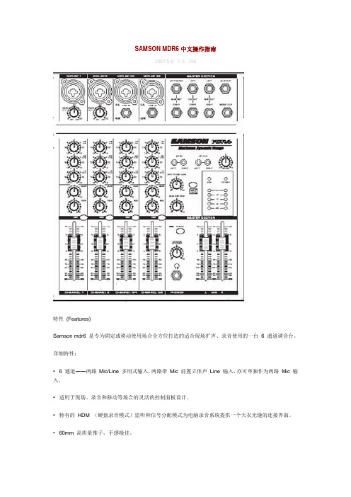
SAMSON MDR6 中文操作指南2007-5-8 点击196特性(Features)Samson mdr6 是专为固定或移动使用场合全方位打造的适合现场扩声、录音使用的一台 6 通道调音台。
详细特性:• 6 通道――两路Mic/Line 多用式输入,两路带Mic 前置立体声Line 输入,亦可单独作为两路Mic 输入。
•适用于现场、录音和移动等场合的灵活的控制面板设计。
•特有的HDM (硬盘录音模式)监听和信号分配模式为电脑录音系统提供一个天衣无缝的连接界面。
•60mm 高质量推子,手感极佳。
•2TK LEVEL 电平控制使你可混和额外的CD, DAT, 磁带,电脑音频或MD 等音频信号。
•每通道的三段均衡可为信号提供精确的修正。
•一路辅助输出,可连接外部效果器、监听等设备。
• 5 级LCD 主输出电平显示表。
•每通道具有高质低噪的话筒前置放大器,提供独立的48v 幻想电源,大动态和透切的音频信号。
•独立模块和精挑元件的高级电路设计使用于台子的每一信号通道。
•高质量的生产工艺保证可靠的操作性能。
• 3 年质量保证。
面板配置篇:控制设置于功能:(controls and functions )前后面板配置:(front and rear panel layout )前面板:•MIC/LINE ――组合式输入连接口,可连接话筒或线性输入。
•GAIN ――用于调节话筒或线性输入的输入电平。
•CLIP ――当话筒的输入信号调节过大则红点闪亮。
(表示输入信号已经过载,信号失真,需把GAIN 适量调小)•HIGH FREQUENC Y ――高频段均衡,+/ -15dB /12kHz 。
•MID FREQUENCE ――中频段均衡,+/ -15dB /2.5kHz•LOW FREQUENCE ――低频段均衡,+/ -15dB /80Hz•AUX ――推子前信号辅助发送,其输出信号用于连接外置效果器或其他监听设备。
samson 工业控制阀 定位器 说明书 3730-0

25.0
3271 型 执行器
120/140/350 700 700
15 7.5 15 和 30
7.0 10.0
35.0 50.0
1400/2800
30
14.0
70.0
1400/2800
60
2ห้องสมุดไป่ตู้.0
100.0
1400/2800
120
40.0
200.0
需要的 反馈杆
指定的连接 销钉位置
S
17
M
25
M
35
紧闭关断功能: 在激活了紧闭关断紧闭功能之后(参考第 5.12 部分),当给定值低于 4.5mA 或超过 19.5mA 时,气动执行器就会完全充气或 排空。 对于三通阀,该功能允许阀芯在执行器以 最大推力移动到终端阀位。
6 EB 8384-0 ZH
设计与工作原理
控制阀 阀位传感器 PD 控制器 DIP 开关 电气转换器 气动放大器 压力定值器 流量定值器 输出气量调整
1400-6822
执行器 附件
连接板用于附加连接电磁阀 G1/8 连接板(旧)用于 3277-5xxxxxx.00 型执行器(旧) 1/8NPT 连接板(新)用于 3277-5xxxxxx.01 型执行器
1400-6820 1400-6821 1400-6823
电磁兼容性
遵守 EN61000-6-2、EN 61000--6-3 标准和 NAWUR 推荐的 NE21 规范
防爆保护 防护等级 外壳材质 重量
II 2 G EEx ia IIC T6/II 2 D IP 65 T 80℃或 II 3 G EEx nA/nL IIC T6/II 3 D IP 65 T 80℃ IP66 压铸铝 EN AC-AL Si12(Fe) (EN AC-44300)根据 DIN 1725 标准,镀铬和喷漆;外部 部件:不锈钢 1.4571 和 1.4301 大约 1kg
A01030257-11高压蒸汽灭菌器(SANYO MLS-3780型)操作规程
作业指导书规范高压蒸汽灭菌器操作程序,正确使用仪器,保证检测工作顺利进行、操作人员人身安全和设备安全.2。
适用范围本作业指导书适用于SANYO MLS-3780型高压蒸汽灭菌器的使用操作。
3。
职责高压蒸汽灭菌器操作人员按照本规程操作仪器,对仪器进行日常维护,做使用登记。
高压蒸汽灭菌器保管人员负责监督仪器操作是否符合规范,对仪器进行定期维护、保养。
科室负责人负责仪器综合管理。
4。
操作程序4。
1 安全操作注意事项仪器管理:必须有专人保管,专人使用;严格遵守操作规程,做好实验记录与善后工作。
对仪器定期进行维护、保养,如仪器出现故障应立即退出检测状态,向保管人员或科室负责人报告,查明原因,及时处理或与该仪器维修站联系,不得擅自“修理",并做好故障登记。
4。
2 技术指标(1)灭菌温度:105℃~135℃;(2)溶解温度:60℃~100℃;(3) 保温温度:45℃~60℃;(4) 压力容器类型:小型压力容器;(5)定时器:灭菌:1~250分钟,器具灭菌过程可设定72小时;溶解:0~250分钟,可设定72小时;保温:72小时后自动切断;预定:1~99小时后;(6)最高使用压力:0。
235MPa;(7)报警安全功能:压力安全阀,防止温升过高,防止空查(烧)盖子联锁装置,防止过压,漏电断路器。
(8)电源:220V 50/60Hz (供电线路20A以上),电力消耗:2千瓦。
(9)有效内容积:80L。
4.3 安全注意事项4.3.1 危险在灭菌室内绝对不能对下列危险性和强碱性物质进行灭菌,以免引起爆炸、腐蚀灭菌室、管道和加速密封圈老化等严重问题。
有害(危险)物质清单:爆炸性物质、可燃性物质、氧化性物质、易燃性物质、可燃性气体。
4.3.2 警告4。
3。
2。
1 电源软线连接到专用连接插口,安装地线、可靠接地。
不要在中途接线延长电源软线,否则会导致触电和火灾发生.4。
3.2。
2 发生异常情况(焦糊味等)时,切断电源开关,断开电源,并与供货商联系。
Sanus 产品说明书.pdf_1718684224.7665863

NFC18 2 4 6 2 4 4 2 4 1 1 1 2 2
1] Remove all parts from package. Damaged or missing parts can be quickly obtained by contacting Sanus Customer Service at (800) 359-5520 or .
small objects can be hazardous to children. For this
reason rubber pads and plastic feet are provided as
b
an option. The decision to use steel spiked feet and
greatly enhance your audio video systemʼs acoustic performance and visual appeal.
Page 1
Where you locate your speakers in your listening room will greatly affect sound quality. All speakers are placement sensitive; moving them a few inches can noticeably change the sound. Take the time to find the ideal speaker locations for your room. The easiest way to find the optimum speaker locations is with educated trial and error. Your Sanus trained audio consultant can get you started in the right direction, but in the end you need to trust your ears. Happy Listening!
SANTOS Santosafe N°37 厨房搅拌机 用户和维护手册说明书

SANTOS: User and maintenance manualUSER AND MAINTENANCE MANUALIMPORTANT: documents included in this manual to be kept:• "CE" COMPLIANCE DECLARATION • WARRANTY CERTIFICATETranslation of the original versionRead the instructions for use before unpacking the appliance.Coffee grinders - Fruit juicers - Mixers - Blenders - Drinks dispensers - Planetary mixers Cheese graters - Ice crushers - Mincers - Vegetable slicers – Dough mixerMoulins à café – Presse-fruits - Mixers – Blenders – Distributeurs de boissons –Batteurs mélangeurs - Pétrin – Râpes à fromage – Broyeurs à glaçons – Hache-viande – Coupe-légumesMODELES DEPOSES FRANCE ET INTERNATIONALINTERNATIONALLY PATENTED MODELSSANTOS SAS :140-150 AVENUE ROGER SALENGRO69120 VAULX-EN-VELIN (LYON) - FRANCEPHONE 33 (0) 472 37 35 29 - FAX 33 (0) 478 26 58 21 - E-Mail:****************www.santos.frKITCHEN BLENDER SANTOSAFE N°37CONTENTS“CE/EU” COMPLIANCE DECLARATION (3)SAFETY RULES (4)INSTALLATION AND HANDLING (4)DO NOT: (4)ELECTRICAL CONNECTION: (5)1st TIME USE (6)RECYCLING THE PRODUCT AT THE END OF ITS SERVICE LIFE (6)DESCRIPTION OF APPLIANCE (7)USING THE APPLIANCE (7)USING FOR THE 1st TIME: (7)Locking the jar clamping rod: (7)Operation: (8)Stopping the appliance: (8)Rotation speed: (8)Mixing solid foods: (8)Ice: (8)Making a mayonnaise: (8)RECOMMENDATIONS WHEN MAKING HOT PREPARATIONS: (9)CLEANING (9)MAINTENANCE (10)Changing the coupling system: (10)Spare parts: (11)Prolonged periods of non-use: (11)FAULT FINDING (12)The machine will not start: (12)The appliance stops following an overload: (12)The motor runs but the blades do not rotate: (12)APPLIANCE TECHNICAL SPECIFICATIONS (13)Electrical wiring diagram: (15)220-240V 50/60Hz wiring diagram (15)Figures (16)WARRANTY CERTIFICATE (17)APPLIANCE IDENTIFICATION PLATE (17)“E C/EU” COMPLIANCE DECLARATIONTHE MANUFACTURER:SANTOS SAS - 140-150, Av. Roger SALENGRO 69120 VAULX-EN-VELIN (LYON) FRANCEdeclares that the appliance intended for the professional market described below: Description: MIXERType number: 37complies with:•the statutory provisions defined in appendix 1 of the European "machines" directive n°2006/42/EC and the national legislation transposing it•the statutory provisions of the following European directives and regulations: o N° 2014/35/EU (low voltage directive)o N° 2014/30/EU (EMC directive)o N° 2011/65/EU (RoHS directive)o N° 2012/19/EU (WEEE directive)o N° 1935/2004/EC (regulation) relating to materials and articles intended to come into contact with foodstuffso N° 10/2011/EU (regulation) plastic materials and articles intended to come into contact with foodHarmonised European standards used to give presumption of conformity with the essential requirements of the above-mentioned directives:•NF EN 12852+A1: 2010, Food processing machinery –Food preparation equipment and blenders - Safety and hygiene requirements.This European standard is a type-C standard as defined in EN ISO 12100. When the provisions ofthis type-C standard differ from those stated in the type-A or B standards, the provisions of the type-C standard override the provisions of the other standards. This standard provides the means tocomply with the requirements of the "machines" directive n°2006/42/CE, (see appendix ZA) •NF EN ISO 12100: 2010: Safety of machinery - General principles for design•NF EN 60204-1: 2018: Safety of machinery - Electrical equipment of machines-General requirements•NF EN 1672-2: 2020, Food processing machinery – Basic concepts – Hygiene requirements•NF EN 60335-1: 2013 Safety of household and similar electrical appliances•EN 60335-2-64:2004 Part 2-64: Particular requirements for commercial electric kitchen machines.Drawn up in VAULX-EN-VELIN on: 01/02/2022Signatory’s position: CHIEF EXECUTIVE OFFICERSignatory’s name: Aurélien FOUQUETSignature:SAFETY RULESAt the time of use, maintenance or scrapping of the appliance, always ensure that the following elementary precautions are adhered to.Read the explanatory instructions in fullKeep this user manualINSTALLATION AND HANDLINGIt is prohibited to hold the appliance by the rod (1) or locking lever (2) The appliance can be installed by one person alone.For ease of use, you are advised to place the appliance on a table or work surface to easily add the ingredients or to monitor the progress(recommended height: 90 cm, to be adapted as required for the user).DO NOT:1. Plunge the base in water or any other liquid for reasons of protection against risks of electrocution.2. Use this applicable to blend, grind or emulsify anything other than foodstuffs3. Pass the pits through the appliance. Remove the pits from fruits before passing them in the appliance (e.g. mangos, apricots, peaches).4. The appliance is not designed for processing frozen foods.5. Do not insert solid ingredients into the mixer before switching it on.6. Do not operate the appliance with the jar empty.7. Do not remove the jar until the blades have stopped completely. 8. Never leave water permanently in the jar.9. Neither a water spray or a pressure spray should be used for cleaning 10. Never attempt to change the blades with the jar on the base.11. Be careful not to get burnt when preparing hot products. The surfaces of the jar and lid may be very hot12. Insert or store kitchen utensils in the jar.13. Operate the appliance if the jar or a blade is chipped, cracked or broken. Never use a jar if there is any play with respect to the blade.14. It is forbidden to operate the appliance on a surface with a slope in excess of 10° relative to the horizontal plane. All 5 feet of the appliance must always be resting on this surface.15. Use of spare parts other than certified original SANTOS parts is prohibited.!!Note: You will find it easier to understand the next few paragraphs if you refer to the diagrams at the end of this manual.16. use the unit with a damaged power cord. it must be replaced by anauthorized dealer or by SANTOS company, or by similarly qualified personsin order to avoid a hazard.17. The appliance must be unplugged before any intervention on it: cleaning,general care, maintenance.18. Connect several appliances to the same power socket.19. Use the appliance outdoors.20. Never place the appliance close to or on a source of heat.21. This appliance is a professional machine designed exclusively forprofessional use. It is not designed for household use.22. This appliance is not designed for use by people (including children) whosephysical, sensorial or mental capacities are impaired or by people with noexperience or knowledge, unless they have been supervised or given trainingin the use of the appliance beforehand by a person responsible for theirsafety.Supervise children to ensure they do not play with the appliance.23. This appliance is intended for use in communal areas, e.g. in the kitchens ofrestaurants, canteens, hospitals and artisan trades such as bakeries,butcher's shops, etc., but not for continuous mass production of food.ELECTRICAL CONNECTION:•The appliance's power supply is available in two single-phase voltages:-100-120 V 50/60 Hz:-220-240 V 50/60 Hz:Note: This appliance can operate at both 50Hz and 60Hz without any adjustments.Line protection: the appliance must be connected to a standard 2 pole + earth socket. The set-up must be fitted with a differential circuit breaker and a 16A fuse. Earthing of the appliance is compulsory.TAKE CARE:•Before connecting the appliance, check that the mains electrical voltage is the same as the voltage for your appliance. Its value is shown:!➢either on the identification plate under the appliance.➢or on the identification plate on the last page of this manual.•If the power cord is damaged, it must be replaced by an authorized dealer or by SANTOS company, or by similarly qualified persons in order to avoid a hazard.TAKE CARE: Check that the on / off switch (3) is in position “OFF” beforeplugging the power cord in to the mains power socket.1st TIME USE!Be careful not to get cut when handling the blades or cleaning insidethe jar.Thoroughly clean all parts in contact with the food.Wash the following with a standard dish washing product: jars (6), lids (7), caps (8).You are not advised to wash the lid seal (9) and the blade seal (16) in a dishwasher. RECYCLING THE PRODUCT AT THE END OF ITS SERVICE LIFEThis appliance is marked with the symbol of the selective waste sortingsystem relating to waste electrical and electronic equipment. This meansthat this product is covered by a selective sorting system in compliance withthe 2012/19/EU Directive (WEEE) - part relating to appliances forprofessional use - so as to be either recycled or dismantled with a view toreducing any impact on the environment.For further information, you can contact SANTOS or your local dealer.For the disposal or recycling of the appliance components, please refer to a specialist company or contact SANTOS.Electronic products not covered by a selective sorting system are potentially dangerous for the environment.The packaging material should be disposed of or recycled in accordance with regulations in force.DESCRIPTION OF APPLIANCEMixer N° 37 is an electrical appliance designed to blend, grind and mix different foodstuffs in the form of liquids, doughs/batters or solids. The most common applications relate to the following preparations:• COOKING : soups – cream soups - sauces - creams - mousses - purées - pâtés - soufflés...• DESSERTS : creams – stewed fruit - batters - milk-shakes - flans - mousses... • DRINKS : fruit, vegetable cocktails - punches - syrups - sangria.USING THE APPLIANCEDo not operate the appliance with the jar empty.USING FOR THE 1st TIME:Locking the jar clamping rod:For your safety, the appliance can only operate when the jar (6) is closed by its lid (7) and correctly positioned on the base (4).Push the handle (2) down to lock or then down again to unlock the jar clamping rod (1).When in the unlocked position (rod in top position), place the jar closed by its lid on the base (4).Push the handle (2) down to lock the jar (6) (rod in lower position). Turn the rotary switch (3) to start up the motor and set the desired speed.!17642315Handle in Locked positionHandle in Unlocked position2Operation:The mixer must always operate with a minimum of liquid in the jar in order to drive solid foods towards the blades.Maximum speed with rotary switch: 15,000 rpmSpeed with PULSE button: 18,000 rpmStopping the appliance:There are two ways to stop the appliance:1. Turn the rotary switch (3) to "OFF" to stop the motor completely, then operate thehandle (2) to release the jar. Wait until the blades have stopped completely beforeremoving the jar from the base.2. During operation at a set speed, push the handle (2) down to unlock the clamping rod(1). This operation will stop the appliance without altering the speed adjustment.Wait until the blades have stopped completely before removing the jar from the base.Rotation speed:The rotation speed of the blades must be adapted to the results desired and the type of foodstuffs to be processed.Mixing solid foods:Dice up dry ingredients and insert them through the opening in the lid (7) when the appliance is in operation.Increase the size of the cubes according to the quantity of food already mixed or "puréed" in the jar.Ice:Do not use the blades to crush blocks of ice.Small ice cubes like those produced by the majority of automatic ice makers can be crushed at low speed.Making a mayonnaise:Put all the ingredients in the jar except for the oil. During operation, remove the cap (8) from the lid and add the oil a little at a time pouring it in evenly.RECOMMENDATIONS WHEN MAKING HOT PREPARATIONS:In order to optimise the operation and safety of the appliance, you are advised to: •Fill the jar according to its functional capacity and not its total capacity•Do not use the pulse button at the start.•Gradually increase the mixing speed.•Replace the blade and lid seal every 6 months when making hot preparations.The seal may loosen when in contact with very hot food and lead to a leakageproblem over time.CLEANINGBe careful not to get cut when handling the blades or cleaning inside the jar.IMPORTANT:•Stop the appliance and unplug the power cord from theappliance.•The appliance should neither be cleaned in a water spray nor !with a pressure spray•The motor unit (4) must not be immersed in water.•Do not use an abrasive sponge to clean the plastic jar (6).•Do not hermetically close the jar when the appliance is stored away(remove the cap (8) from the lid).You are advised to clean the appliance as soonas you have finished using it.It will be easier to clean if you do not allow theremaining scraps of food to dry.For thorough cleaning, take apart the parts of the jar(unscrew the jar (6) from the handle base (5)) andwash them with hot soapy water, rinse and dry.The base can be cleaned using a soft, wet sponge.6Unscrewing75 9MAINTENANCEPrior to carrying out any intervention on the appliance, it must be disconnected from the mains without fail.Changing the coupling system:When changing the couplings, make sure you adhere to the position of each component:• flexible coupling (11) on the motor unit • rigid coupling (12) on the blade holder.IMPORTANT: Motor end:Turn the screw (13) counter clockwise to remove the flexible coupling (11). Blade end:Turn the screw (14) counter clockwise to remove the rigid coupling (12).REMARKS: for N°37 versions prior to 2012, screw (13) must be turned clockwise to remove the flexible coupling (11).!Loosening direction of fixing screw, motor end: counter clockwise Loosening direction of fixing screw, jar end: counterclockwise14 12 11 13Spare parts:IMPORTANT: use of spare parts other than certified original SANTOS parts !is prohibitedThis machine requires no specific maintenance. The bearings are lubricated for life.If any intervention is necessary to replace parts subject to wear, such as the couplings, blades, jar seals, electrical or other components, please refer to the parts lists (see the exploded view at the end of this manual).For all spare part orders (see references in the exploded view at the end of the manual), state:➢the type➢the appliance serial number and➢the electrical specificationsgiven under the appliance.Prolonged periods of non-use:There are no problems with this appliance in the event of prolonged periods of non-use. You are simply advised to clean it before use and check that the components of the appliance are in good condition (e.g. power cord, seals and other spare parts).FAULT FINDINGIdentifying the cause of appliance stoppage with precision.If the problem persists, switch off the power supply to the appliance (unplug the cord from the mains socket) and call in the maintenance service or contact a SANTOS approved dealer.The machine will not start:•Check : the mains supply, the condition of the power cord•To run the motor of the mixer the jar (6) with its lid (7) closed must be placed on the base(4) and locked using the clamping rod (1).•Check that there is no food that is too hard or big jamming the blades (10).The appliance stops following an overload:•If the motor stalls during operation, reduce the load, allow the appliance to cool down for several tens of minutes.•Check that there is no food that is too hard or big jamming the blades (10).The motor runs but the blades do not rotate:•Check the condition of the coupling system. If required, change the 2 parts at the same time.(see "maintenance” section)APPLIANCE TECHNICAL SPECIFICATIONSModel n° 37Power supply voltage (V) 220-240Frequency (Hz) 50/60Motor (1)Input power (W) 1550Max. current (A) 8Speed (rpm) 0 to 18000Operating cycle (3) Intermittent Cycle:10min ON/10min OFF2L jar capacity (L) 1.54L jar capacity (L) 3Dimensions: Height (mm) 566Width (mm) 220Depth (mm) 303Weight: Net weight (kg) 12Packaged weight (kg) 14Noise: (2) L pAaccuracy K pA = 2.5dB(dBA) 66(1) These ratings are given for your guidance. The exact electrical specifications of your appliancecan be found on the rating plate.(2) Noise level measured in acoustic pressure of appliance loaded as per the standard ISO11201:1995 and ISO 4871:1996.Appliance placed on a work surface at 75cm from the floor. Microphone turned towards the appliance at 1.6 m from the floor and 1 m from the appliance.(3) Operating cycleThe professional appliance is designed for intermittent use according to an intermittent cycle of10 minutes on, 10 minutes off.This cycle corresponds to the operating time to perform the function and the stopping time for the preparation and serving of the products processed, in compliance with the instructions of the standard: EN 60335-2-64+A1:2004 Part 2-64: Particular requirements for commercial electric kitchen machines.ITEM Description1 Clamping rod2 Locking handle3 Switch, speed adjustment4 Motor unit5 Jar handle6 Jar7 Lid8 Cap of lid9 Lid seal10 Blade assembly11 Flexible motor coupling12 Rigid jar coupling13 Motor coupling screw14 Blade coupling screw15 PULSE button16 Blade sealElectrical wiring diagram:220-240V 50/60Hz wiring diagramFGBDNEIJAUNE YELLOW GELB GEEL AMARILLO GIALLO BLANC WHITE WEISS WIT BLANCO BLANCO NOIR BLACK SCHWARZ ZWART NEGRO NERO BLEU BLUE BLAU BLAUW AZUL BLU ROUGE RED ROT ROOD ROJO ROSSO MARRON BROWN BRAUN BRUN MARRON MARRONE ORANGE ORANGE ORANGE ORANJE NARANA ARANCIONE VIOLET VIOLET VIOLETT VIOLET VIOLETA VIOLA GRISGREYGRAUGRIJSGRISGRIGIOVERT/JAUNEGREEN/YELLOWGRÜN/GELBGROEN / GEELVERDE/AMARILLOVERDE/GIALLOMOTEURVert Rouge BlancGris MarronBlancUNITE ELECTRONIQUE DECONTROLEPotentiomètre Réglage de vitesseFILTRE ANTI -PARASITES220-240 V ~MarronNoirBlancGrisViolet OrangeViolet OrangeGris Blanc PulseMarronNoir Interrupteur manetteNoir Marron NoirBlanc OrangeGris GrisVert/jauneVert/jauneBlanc12 JauneRougeFigures5213978 4 61015106579 87Loosening direction of fixing screw, motor end: counterclockwiseLoosening direction of fixing screw, jar end: counterclockwise1412 1113WARRANTY CERTIFICATEWARRANTYSince the 01.01.95, all our appliances comply with CE and possess the CE label. Our guarantee is of 24 months from the manufacturing date mentioned on the descriptive plate, except concerning the asynchronous motors (consisting of a rotor and a stator) which are warranted for 5 years from their manufacturing date. Warranty is strictly limited to the free replacement of any part of origin recognized by us as defective due to a defect or building default and identified as belonging to the concerned appliance. Warranty does not apply to damages resulting from installation or use non-complying with our appliance data sheet (user’s manual) or in case of an evident lack of maintenance or disrespect of elementary security electric rules. It does not apply in case of regular wear and tear.Any replacement of parts under warranty will be realized after return of the defective part in our workshops, postage paid, supported by a copy of a conformity statement on which appears the serial number of the appliance. Every appliance is equipped with a descriptive plate conforming to the EC recommendations and of which a duplicate exists in the conformity statement (serial number, manufacturing date, electrical characteristics …). In case of serious damage judged repairable only in our workshops, and after prior consent from our departments, any appliance under guarantee is sent by the Distributor, carriage paid. In case of repairs or reconditioning of appliances not under guarantee, the round trip transport is payable by the distributor. The parts and workforce are invoiced at the current rate. A preliminary estimate can be supplied.Coffee grinder not using SANTOS original burrs are not taken under guarantee. The warranty conditions, repairs, reconditioning, of the espresso coffee grinder are the object of a specific note. Our guarantee does not extend to the payment of penalties, the repair of direct or indirect damages and notably to any loss of income resulting from the nonconformity or the defectiveness of products, SANTOS's global responsibility being limited to the sale price of the delivered product and to the possible repair of the defective products.In case of revelation of an imperfection during the warranty period, the Distributor has to, unless a different written agreement of SANTOS, indicate to his customer to stop any use of the defective product. Such a use would release SANTOS of any responsibility.APPLIANCE IDENTIFICATION PLATESPECIMENFor all documents not supplied withappliance.Printed, Faxed, Downloaded。
SAMSONCValve话放中文说明书样本
SAMSON C.valve 中文操作指南特性简介(features):Samson c valve 话筒/ 乐器前置放大器使用最新电路设计技术,下面将简介一下它重要特性:•结合晶体管和电子管两套独立放大单元一种高质量话筒/ 乐器前置放大器。
•内置输出电平压缩器可满足录音或现场扩生使用规定。
•谐波泛音总量或“温暖度”可由saturation ( 饱和度) 旋钮控制。
•一种输入电平旋钮,控制话筒或乐器最大输入电平量。
•一种预设内置均衡器,由vocal EQ 按钮控制开关。
•带反相开关(phase )可调节输入信号相位。
•一种模仿VU 批示表可以容易监控输出电平。
•可为电容话筒提供48v 幻想电源。
只需按下前面板“ 48v ”按钮。
•S/PDIF 同轴数字输出,内置一高质量AD 转换芯片,可通过背面板莲花同轴接口为硬盘录音机等录音设备提供一种24bit 数码信号。
•通过前面板48/96k 按钮可选取同轴输出采样频率。
• 6 段LED 输入电平批示表显示输入电平增益。
•包括1/4 〞(6.3mm )插入输入接口可便利连接其她线性输入设备。
•平衡XLR 话筒输入和1/4 〞(6.3mm )乐器线路输入。
•特大号斜面橡胶脚垫可完美将samson c class 系列其她解决器堆叠在一起。
•典型“蓝精灵”蓝色面板。
经久耐看。
•三年质量保证。
面板简介篇(layout ):前面板:1,INPUT GAIN -输入增益,旋转式旋钮,用于调节输入电平。
2. LOW FREQUENCY -低频选取旋钮,当激活低切功能时用以选取低切频段。
3. INPUT METER -6 段LED VU 电平批示表,显示输入增益变化量。
4. SATURATION -饱和度,用以调节电子管电路谐波泛音量,即温暖度。
5. PILOT LIGHT -电子管工作批示灯,当此灯完全点亮时,表达电子管电路已进入可使用状态。
6. VOLUME -控制总输出电平量。
索芬森DCS系列电源供应器操作手册说明书

1.4 Specifications
1.4.1 Electrical Specifications1
MODELS
8-125
20-SO
• Adjustable Over-Voltage Protection (OVP)
• External TIL, AC or DC shutdown
• Remote voltage, current limit and OVP programming with selectable programming constants.
2 For input vohage variation over the AC input vohage range, with constant rated load
3 For 0-100010 load variation, with constant nominal line vohage 4 Typical pop noise and ripple is sOmv
Additional Characteristics
MODELS
8-125
20-SO
33-33
40-25
60-18
Stabilityl:
Vohage
4mV
IOmV
16.SmV 20mV
30mV
Current Temperature Coefficient2;
62.SmA 2SmA
16.SmA 12.SmA 9mA
Revision B (10/95)
SAMSON S-amp 说明书

Table Of ContentsIntroduction and Features3 Front and Rear Panel Layout 4Operating the S amp 5-6 Typical Set-Up6Headphone Impedance and Sensitivity Ratings 7Specifications 8Copyright 2003, Samson T echnologies Corp.Printed January 2003Samson T echnologies Corp.575 Underhill Blvd.P.O.Box 9031Syosset, NY 11791-9031Phone:1-800-3-SAMSON (1-800-372-6766)Fax:516-364-3888S amp Introduction and Features IntroductionThank you for purchasing the S amp miniature headphone monitor system from Samson Audio! S amp provides an elegant solution for headphone monitoring, either on stage or in the studio.The S amp is a specially designed headphone amplifier that allows you to control the level balance between four sets of headphones.Providing unusually high power levels and superb audio fidelity, the S amp is compatible with virtually all popular headphone models.And just because this unit is miniature, don’t be surprised with its great sound and reliability, thanks to the use of high quality com-ponents and solid build construction.In this manual, you’ll find a more detailed description of the features of the S amp, as well as a guided tour through the front and rear panels, step-by-step instructions for using the S amp, a reference chart that gives impedance and sensitivity ratings for a number of popular headphone models, and full specifications.Y ou’ll also find a war-ranty card enclosed—please don’t forget to fill it out and mail it so that you can receive online technical support and so we can send you updated information about other Samson products in the future.S amp Features•Four channel stereo headphone amplifiers•Maximum output power on each channel regardless of different headphone impedances•Four 1/4-inch stereo headphone outputs•Individual volume control for each headphone output•Stereo 1/4 inch input connector•Rugged aluminum extrusion chassis•Large rubber bumper feet•18 Volt AC adapter included•Three year extended warranty•Turn the four headphone channel LEVEL knobs to their minimum (fully counter-clockwise) setting.•Plug the S amp power adapter into a wall outlet.•Apply a signal, like the output of a mixer playing a CD, to the S amp’s STEREO INPUT jack.•Connect a set of headphones to Channel 1 and slowly turn the channel’s LEVELknob clockwise until you hear the desired level.Headphone Impedance and Sensitivity RatingsSAMSON HEADPHONESMod e l Imp e danc e S e nsitivity /mWPH6032 ohm 100 dB RH10064 ohm 106 dB RH30032 ohm 106 dB RH60040 ohm 106 dB CH7032 ohm 103 dB CH70064 ohm 108 dBOTHER MANUFACTURER'S HEADPHONES Manufactur e r Mod e l Imp e danc e S e nsitivity /mWAKG K-141 600 ohm 98 dB AKG K-240 600 ohm 88 dB Beyer DT-150 250 ohm 114 dB Beyer DT-801 250 ohm 114 dB Fostex T-10 50 ohm 91 dB Fostex T-20 50 ohm 96 dB Fostex T-40 50 ohm 98 dB Sennheiser HD-450 (original) 70 ohm 94 dB Sennheiser HD-450 Series II 60 ohm 94 dB Sony MDR-7502 45 ohm 100 dB Sony MDR-7504 45 ohm 103 dB Sony MDR-7506 63 ohm106 dBVirtually all headphones that terminate in a stereo 1/4" plug can be used with the S amp Headphone Amplifier.This chart provides a partial listing of some of the more popular models, along with their impedance and sensitivity ratings.As described on page 4 of this manual, headphones with lower impedances (or higher sensitivity) will sound louder as compared to other, higher impedance (or lower sensitivity) headphones at the same chan-nel Volume setting.Samson Technologies has no connection with any of these manufac-turers, nor do we endorse any particular models for use with the S amp.This is simply areference listing for your convenience.For more information about any of these head-phones, contact the manufacturer directly.S amp SpecificationsInput Impedance:100K ΩunbalancedMax Input Level:+19 dBVInput Connectors:Stereo 1/4”TRS phoneOutputs:(4) 1/4”Stereo 1/4”Output Impedance:100 Ωeach outputMax Gain:20 dB/ChannelS/N Ratio:>90 dBTHD:<.005%IMD (SMPTE)<.005%Power:18 VDC adapterDimensions: 5.65”L x 4.13”W x 2”H (144mm L x 105mmW x 51mm H)Weight:16.5 oz., 419 gm.Samson T echnologies Corp.575 Underhill Blvd.P.O.Box 9031Syosset, NY 11791-9031Phone:1-800-3-SAMSON (1-800-372-6766)Fax:516-364-3888。
索芬森高功率可扩展可编程DC系列产品说明书
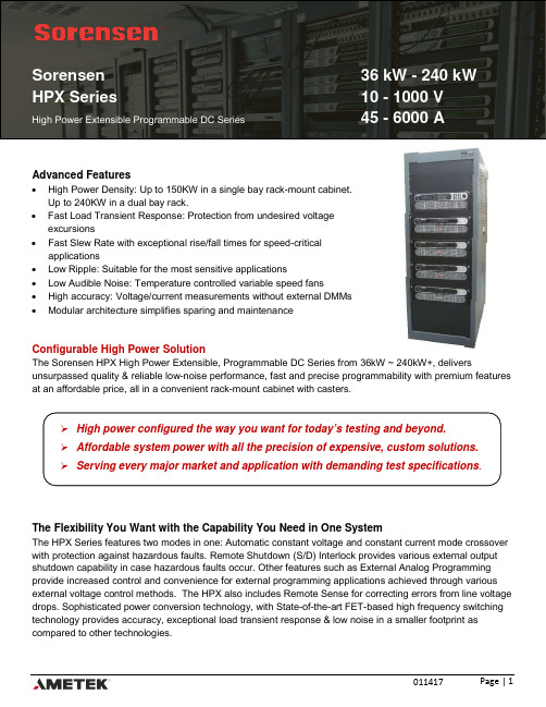
Sorensen36 kW - 240 kW HPX Series10 - 1000 VHigh Power Extensible Programmable DC Series 45 - 6000 AAdvanced Features•High Power Density: Up to 150KW in a single bay rack-mount cabinet.Up to 240KW in a dual bay rack.•Fast Load Transient Response: Protection from undesired voltageexcursions•Fast Slew Rate with exceptional rise/fall times for speed-criticalapplications•Low Ripple: Suitable for the most sensitive applications•Low Audible Noise: Temperature controlled variable speed fans•High accuracy: Voltage/current measurements without external DMMs•Modular architecture simplifies sparing and maintenanceConfigurable High Power SolutionThe Sorensen HPX High Power Extensible, Programmable DC Series from 36kW ~ 240kW+, delivers unsurpassed quality & reliable low-noise performance, fast and precise programmability with premium features at an affordable price, all in a convenient rack-mount cabinet with casters.The Flexibility You Want with the Capability You Need in One SystemThe HPX Series features two modes in one: Automatic constant voltage and constant current mode crossover with protection against hazardous faults. Remote Shutdown (S/D) Interlock provides various external output shutdown capability in case hazardous faults occur. Other features such as External Analog Programming provide increased control and convenience for external programming applications achieved through various external voltage control methods. The HPX also includes Remote Sense for correcting errors from line voltage drops. Sophisticated power conversion technology, with State-of-the-art FET-based high frequency switching technology provides accuracy, exceptional load transient response & low noise in a smaller footprint as compared to other technologies.Markets and ApplicationsThe HPX Series is designed for testing today’s complex electronics, including telecommunications, aerospace and commercial electronics requiring sophisticated programmability with high power density. Applications include:•Telecommunications & IT •Industrial Automation & Process Control •Magnets, RF Amplifiers & Beam Steering •Heater Supplies•Battery, Ultracapacitor & Energy Storage Testing •Material Research•Electroplating, Sputtering & Coating •Electrical Component Validation•Burn-in & Lights-out Testing •Laser Diode Validation & Testing•PV Inverter, Fuel Cell & Renewable Energy R&D •Aerospace & Satellite Testing•Test & Measurement •Water Treatment & Purification •Semiconductor Processing •Industrial Automation•Gas, Chemical, Petroleum & Utility Plants •EOL Test, QC and Inspection •Defense, Military & Aerospace ATE •Automotive Component, ECU & HIL Testing •Compliance TestingModular Architecture Benefits•The HPX system does not go down in the event that one of the power building blocks fails. •Modularity also allows more efficient maintenance as sparing can be done at the building block level.Intelligent controls allow for sophisticated sequencing, constant power mode to allow for independent settings of max voltage, current and power and save/recall of the supply settings.•Flexible control includes front panel manual control, isolated analog input, RS232 and Ethernet (LXI) with an option to replace the Ethernet interface with IEEE-488.SpecificationsInput PowerVoltage (Standard) 440/480 VAC ±10% (allowed range 396-528 VAC)Voltage (Options) 208/220 VAC ±10% (allowed range 187-242 VAC) (for power levels to 75KW) 380/400 VAC ±10% (allowed range 342-440 VAC)Frequency 47 to 63 HzPhases 3–phase, 3–wire plus ground. Not phase rotation sensitive. Neutral not used. Power Factor 0.9 typicalEfficiency 87% typical at full load, nominal line for 40-1000V models 85% typical at full load, nominal line for 10-30VDC modelsLoad RegulationVoltage 0.02% of maximum output voltage for 40-1000V models 0.05% of maximum output voltage for 10-30VDC modelsCurrent 0.1% of maximum output current Load RegulationVoltage 0.02% of maximum output voltage for 40-1000V models 0.05% of maximum output voltage for 10-30VDC modelsCurrent 0.1% of maximum output current OtherTransient Response Recovers within 1ms to ±0.75% of full scale output for a 50% to 100% or 100% to 50% load changeDown Programming With full load, the output will program from 100% to 10% in less than 10 secondsVoltage Stability ±0.05% of set point after 30-min warm-up > 8 hrs. with fixed line, load, and temperature at sense points.Temperature Coefficient 0.02%/°C of max output voltage rating for voltage set point, typical 0.03%/°C of max output current rating for current set point, typicalCooling Internal fans in all power supplies, w/ additional fans in racks above 60 kW. Vents from front to rear <60kW.Humidity 95% maximum, non-condensing, 0 to 50°C; 45°C maximum wet-bulb temperature Operating Temperature 0 to 50°CStorage Temperature -25° to 65°CAltitude Operating full power available up to 5,000 ft (1524 m)Front Panel and Remote Digital ProgrammingVoltage ±0.1% of full-scaleCurrent ±0.4% of full-scaleOvervoltage Protection (OVP) ±1% of full-scale outputFront Panel Meter AccuracyVoltage ±0.1% of full-scaleCurrent ±.4% of full-scaleRemote Digital ReadbackVoltage ±0.15% of full-scaleCurrent ±0.4% of full-scaleRemote Analog ProgrammingVoltage ±0.25% of full-scale output for 0-5V range (±0.5% 0-10V range) Current ±1% of full-scale output for 0-5V range (±2% 0-10V range) Overvoltage Protection ±1% of full-scale outputRemote Analog ReadbackVoltage ±1% of full-scale output, 0-10V rangeCurrent ±1% of full-scale output, 0-10V rangeResistive ProgrammingVoltage (0-100%) 0-5 kΩCurrent (0-100%) 0-5 kΩVoltage ProgrammingVoltage (0-100%) 0-5 VDC or 0-10 VDCCurrent (0-100%) 0-5 VDC or 0-10 VDCOvervoltage Protection (OVP) 0.25-5.5 VDCRemote Analog ControlInput to Output Isolation The control signal return for Non-Isolated Analog programming is connected to the negative output terminal. Negative terminal should not exceed 300V to earth ground. The max. voltage with Remote Isolated Analog programming (option) to the negative output terminal is 600V.Remote SensingRemote Sensing Terminals are provided to regulate output voltage at point of load. Maximum line drop is 5% of rated output voltage per line for 40-100V models, 2% of rated output voltage per line for >100V models, 1V for 10-20V, 1.5V for 30VDimension36, 45 & 60kWModels 75, 90 & 105kWModels120, 135 & 150kWModels180, 210 & 240kWModelsWidth 24 in (55.9 cm) 24 in (55.9 cm) 24 in (55.9 cm) 48 in (122 cm) Depth 36 in (96.5 cm) 36 in (96.5 cm) 36 in (96.5 cm) 36 in (96.5 cm) Height 49.5 in (129.73 cm) 73 in (185.42cm) 80 in (203.2cm) 73 in (185.42cm)Options & Order InformationInput Voltage OptionsE (Standard) Input Voltage 440/480VAC L-L +/- 10% (396-528VAC L-L) D (Option)Input Voltage 380/400VAC L-L +/- 10% (342-440VAC L-L)C (Option)Input Voltage 208/230VAC L-L +/- 10% (187-253VAC L-L, power levels up to 75KW)Remote Control Options0ANo Options1A IEEE-488.2 + RS-232C (RS-232 comes standard) 1C Ethernet / RS-232 1D Isolated Analog Control 2A Combined Options, 1A + 1D 2GCombined Options, 1C + 1DModifications*000 No OptionsE00 Addition of AC input circuit breaker and EPO switch with local and remote trip of AC breaker (consult factory for pricing)0R0 Replace ‘L’-mounting brackets with rack slides 00WExtended Warranty*Modifications can be ordered in any combination, e.g, 0RW = Rack slides and extended warranty optionsH P X100 X 1200 E - 1A 000VoltageModificationsModels by Voltage and Power:1) Power factor correction will be standard (included) on all high power systems.2) Cons. Fact. means “consult factory.”。
戴尔Inspiron 3780设置和规格说明书

Inspiron 3780Setup and SpecificationsNotes, cautions, and warningsNOTE: A NOTE indicates important information that helps you make better use of your product.CAUTION: A CAUTION indicates either potential damage to hardware or loss of data and tells you how to avoid the problem.WARNING: A WARNING indicates a potential for property damage, personal injury, or death.© 2018 Dell Inc. or its subsidiaries. All rights reserved. Dell, EMC, and other trademarks are trademarks of Dell Inc. or its subsidiaries. Other trademarks may be trademarks of their respective owners.2018 - 12Rev. A001 Set up your Inspiron 3780 (4)2 Create a USB recovery drive for Windows (6)3 Views of Inspiron 3780 (7)Right (7)Left (7)Base (8)Display (9)Bottom (9)4 Specifications of Inspiron 3780 (11)Dimensions and weight (11)Processors (11)Chipset (12)Operating system (12)Memory (12)Ports and connectors (13)Communications (13)Ethernet (13)Wireless module (14)Audio (14)Storage (15)Media-card reader (15)Intel Optane memory (optional) (15)Keyboard (16)Camera (16)Touchpad (17)T ouchpad gestures (17)Power adapter (17)Battery (18)Display (18)Fingerprint reader (optional) (19)Video (20)Computer environment (20)5 Keyboard shortcuts (21)6 Getting help and contacting Dell (23)Self-help resources (23)Contacting Dell (23)Contents3Set up your Inspiron 3780 NOTE: The images in this document may differ from your computer depending on the configuration you ordered.1Connect the power adapter and press the power button.NOTE: T o conserve battery power, the battery might enter power saving mode. Connect the power adapter and pressthe power button to turn on the computer.2 Finish operating system setup.For Ubuntu:Follow the on-screen instructions to complete the setup. For more information about installing and configuring Ubuntu, see the knowledge base articles SLN151664 and SLN151748 at /support.For Windows:Follow the on-screen instructions to complete the setup. When setting up, Dell recommends that you:•Connect to a network for Windows updates.NOTE: If connecting to a secured wireless network, enter the password for the wireless network access whenprompted.•If connected to the internet, sign-in with or create a Microsoft account. If not connected to the internet, create an offline account.•On the Support and Protection screen, enter your contact details.3 Locate and use Dell apps from the Windows Start menu—RecommendedTable 1. Locate Dell apps1 4Set up your Inspiron 37804 Create recovery drive for Windows.NOTE: It is recommended to create a recovery drive to troubleshoot and fix problems that may occur with Windows.For more information, see Create a USB recovery drive for Windows.Set up your Inspiron 37805Create a USB recovery drive for Windows Create a recovery drive to troubleshoot and fix problems that may occur with Windows. An empty USB flash drive with a minimum capacity of 16 GB is required to create the recovery drive.NOTE: This process may take up to an hour to complete.NOTE: The following steps may vary depending on the version of Windows installed. Refer to the Microsoft support site forlatest instructions.1 Connect the USB flash drive to your computer.2 In Windows search, type Recovery.3 In the search results, click Create a recovery drive.The User Account Control window is displayed.4 Click Yes to continue.The Recovery Drive window is displayed.5 Select Back up system files to the recovery drive and click Next.6 Select the USB flash drive and click Next.A message appears, indicating that all data in the USB flash drive will be deleted.7 Click Create.8 Click Finish.For more information about reinstalling Windows using the USB recovery drive, see the Troubleshooting section of your product's Service Manual at /support/manuals.6Create a USB recovery drive for WindowsViews of Inspiron 3780 Right1SD-card slotReads from and writes to the SD card.2USB 2.0 portConnect peripherals such as external storage devices and printers. Provides data transfer speeds up to 480 Mbps.3Optical driveReads from and writes to CDs, DVDs, and Blu-ray discs.NOTE: Blu-ray support is only available in certain regions.4Security-cable slot (wedge-shaped)Connect a security cable to prevent unauthorized movement of your computer.Left1Power-adapter portConnect a power adapter to provide power to your computer.2HDMI portConnect to a TV or another HDMI-in enabled device. Provides video and audio output.3Network portConnect an Ethernet (RJ45) cable from a router or a broadband modem for network or Internet access.4USB 3.1 Gen 1 ports (2)Connect peripherals such as external storage devices and printers. Provides data transfer speeds up to 5 Gbps.Views of Inspiron 378075Headset portConnect headphones or a headset (headphone and microphone combo).Base1Left-click areaPress to left-click.2T ouchpadMove your finger on the touchpad to move the mouse pointer. Tap to left-click and two finger tap to right-click.3Right-click areaPress to right-click.4Power button with optional fingerprint readerPress to turn on the computer if it is turned off, in sleep state, or in hibernate state.When the computer is turned on, press the power button to put the computer into sleep state; press and hold the power button for 4 seconds to force shut-down the computer.If the power button has a fingerprint reader, place your finger on the power button to log in.NOTE: You can customize power-button behavior in Windows. For more information, see Me and My Dell at/support/manuals.8Views of Inspiron 3780Display1CameraEnables you to video chat, capture photos, and record videos.2Camera-status lightTurns on when the camera is in use.3MicrophoneProvides digital sound input for audio recording, voice calls, and so on.Bottom1Left speakerProvides audio output.2Service Tag labelViews of Inspiron 37809The Service T ag is a unique alphanumeric identifier that enables Dell service technicians to identify the hardware components in your computer and access warranty information.3Right speakerProvides audio output.10Views of Inspiron 37804Specifications of Inspiron 3780 Dimensions and weightT able 2. Dimensions and weightProcessorsT able 3. ProcessorsChipsetT able 4. ChipsetOperating system•Windows 10 Home (64-bit)•Windows 10 Professional (64-bit)•UbuntuMemoryT able 5. Memory specificationsPorts and connectors T able 6. Ports and connectorsCommunications EthernetT able 7. Ethernet specificationsWireless module T able 8. Wireless module specificationsAudioT able 9. Audio specificationsStorageT able 10. Storage specificationsMedia-card readerT able 11. Media-card reader specificationsIntel Optane memory (optional)Intel Optane memory functions only as a storage accelerator. It neither replaces nor adds to the memory (RAM) installed on your computer.NOTE: Intel Optane memory is supported on computers that meet the following requirements:•7th Generation or higher Intel Core i3/i5/i7 processor•Windows 10 64-bit version or higher (Anniversary Update)•Latest version of Intel Rapid Storage T echnology driverT able 12. Intel Optane memoryKeyboardT able 13. Keyboard specificationsCameraT able 14. Camera specificationsTouchpadT able 15. Touchpad specificationsTouchpad gesturesFor more information about touchpad gestures for Windows 10, see the Microsoft knowledge base article 4027871 at .Power adapterT able 16. Power adapter specificationsBatteryT able 17. Battery specificationsDisplayT able 18. Display specificationsFingerprint reader (optional) T able 19. Fingerprint reader specificationsVideoT able 20. Video specificationsT able 21. Video specificationsComputer environment Airborne contaminant level: G1 as defined by ISA-S71.04-1985T able 22. Computer environment* Measured using a random vibration spectrum that simulates user environment.† Measured using a 2 ms half-sine pulse when the hard drive is in use.‡ Measured using a 2 ms half-sine pulse when the hard-drive head is in parked position.Keyboard shortcuts NOTE: Keyboard characters may differ depending on the keyboard language configuration. Keys used for shortcuts remain the same across all language configurations.Some keys on your keyboard have two symbols on them. These keys can be used to type alternate characters or to perform secondary functions. The symbol shown on the lower part of the key refers to the character that is typed out when the key is pressed. If you press shift and the key, the symbol shown on the upper part of the key is typed out. For example, if you press 2, 2 is typed out; if you press Shift + 2, @ is typed out.The keys F1-F12 at the top row of the keyboard are function keys for multi-media control, as indicated by the icon at the bottom of the key. Press the function key to invoke the task represented by the icon. For example, pressing F1 mutes the audio (refer to the table below). However, if the function keys F1-F12 are needed for specific software applications, multi-media functionality can be disabled by pressing Fn + Esc. Subsequently, multi-media control can be invoked by pressing Fn and the respective function key. For example, mute audio by pressing Fn + F1.NOTE: You can also define the primary behavior of the function keys (F1–F12) by changing Function Key Behavior in BIOS setup program.T able 23. List of keyboard shortcutsThe Fn key is also used with selected keys on the keyboard to invoke other secondary functions.5Keyboard shortcuts21T able 24. List of keyboard shortcuts22Keyboard shortcutsGetting help and contacting Dell Self-help resourcesYou can get information and help on Dell products and services using these self-help resources:T able 25. Self-help resourcesIn Windows search, typeContacting DellT o contact Dell for sales, technical support, or customer service issues, see /contactdell.NOTE: Availability varies by country and product, and some services may not be available in your country.NOTE: If you do not have an active internet connection, you can find contact information on your purchase invoice, packing slip, bill, or Dell product catalog.6Getting help and contacting Dell23。
SANYO三洋高压蒸汽灭菌器MLS-3750MLS-3780使用说明书
电源软线连接到专用连接插口
警告
酒精 煤气 汽油
请使用 <MLS-3750型>单相交流100伏、20安以上 <MLS-3780型>单相交流200伏、20安以上 的专用连接插口连接电源软线,否则有可能引起着火和异常动作而造成人员 受伤。
白:AC 黑:AC 绿:地线
1
安装地线、可靠接地
警告
地线安装可靠
不要接长电源软线
● 务必使本灭菌器的沸点设定符合设置区域的海拔高度。在购买灭菌器 时,沸点设定至100℃。在设置于海拔高度500米以上的区域时,请委 托出售灭菌器的商店设定沸点。
危险
劳动安全卫生法施行令附表1中规定的 ·爆炸性物质 ·易燃性物质 ·氧化性物质 ·可燃性物质 ·可燃性气体 不得放置于本灭菌器附近。
使用前
设置
● 本灭菌器务必设置在地面平整且坚实的地方,将其四个脚轮全部锁定 (ON)。
● 请不要手持控制盘部分移动灭菌器。 移动灭菌器时,请松开(OFF)脚轮,牢牢地支持住灭菌器进行移动。 有台阶或不平整地面等时,请手持把手,小心移动脚步。
● 请不要将灭菌器设置在以下地方,否则会导致故障发生。
·受阳光直接照射的地方 · 高湿度的地方
2
安全注意事项
警告
不要让灭菌物品堵塞灭菌器内的孔和温度传感器 不要让灭菌物品挤压灭菌器箱内的温度传感器
孔 温度传感器
孔
否则会导致控制失效和灭菌不充分。
仅对烧杯、烧瓶、试管等容器本身灭菌时,将 其开口朝下、或者横向放置。
温度传感器
否则,会导致控制失效和灭菌不充分。
灭菌袋装入300毫升左右的水并让袋口保持敞开 状态进行灭菌
否则会引起触电。
不要用钉子钉电源软线
否则会使电源软线发热,导致着火。
- 1、下载文档前请自行甄别文档内容的完整性,平台不提供额外的编辑、内容补充、找答案等附加服务。
- 2、"仅部分预览"的文档,不可在线预览部分如存在完整性等问题,可反馈申请退款(可完整预览的文档不适用该条件!)。
- 3、如文档侵犯您的权益,请联系客服反馈,我们会尽快为您处理(人工客服工作时间:9:00-18:30)。
SAMSON 3780说明书调节阀维护及操作规程DCS系统对调节阀的控制主要通过调节阀自身的电气阀门定位器完成。
我司生产线上的调节阀为德国SAMS ON调节阀,SAMSON调节阀采用智能数字阀门定位器(3780,HART协议数字通信),其控制精度高,运行稳定。
定位器的主要性能介绍如下:结构与工作原理HART电气定位器是为连接气动调节阀而设计的,它可确保阀杆位置(受控变量)与控制信号(参考变量)之间的对应关系。
它将控制装置 4至20mA的输出信号和调节调的行程相比较,并产生一个相应的压力信号作为输出变量。
为此,用户需要提供辅助气源压力1.4-6巴。
定位器辅助能源是由4到20mA参考变量信号提供。
定位器由一个感应,非接触或位移传感系统,一个由2/2-通开关阀组成的电控阀块以及一个电控单元组成。
电控单元包含两个用于处理控制算法及管理通讯的微控器.一旦实际阀门行程值(实际值)与参考变量(设定点)之间出现偏差,微控器就会产生一个二进制脉冲调制信号去控制两个 2/2通开关阀,且分别由一个指定的放大器来控制。
其中一个阀控制排气,另一个控制气源.气源阀(3)将供气(7气源压力1·46巴)送到执行器(填充)。
排气阀(将执行器排出空气流排放到大气中(排气)。
这些开关阀即可以有开关状态—一常开。
常闭—一也可产生可变宽度的单脉冲。
对于这两个受控_阀门,阀林将会移动到与参考变连量相对应的位置。
如果没有系统偏差气源阀和排气阀都将关闭。
作为一个标准功能,定位器配有一个故障信息输出(根据DDN19Z34,NANUR标准的进制输出),用于向控制室发送故障信号。
成的激活位于定位器铰接盖上的写保护开关‘可防止设定被HART通讯修改。
作为对标准定位器型号的补充,有几个附加的选项用于扩展定位器功能。
带眼位开关的定位器为了在故障一安全电路中指示出阀门的最终位置,两个软件限位开关或两个接近开关被带强制排空功能的定位器一个控制定位器的6-24V电压信号,使得信压力施加到执行器。
如果此电压减小信号压力被切断;执行器被排空。
执行器弹簧带动阀门移动到故障一安全位置。
位置变进器是一个本安型,由定位器的微控器控制的两线制变送器。
它为阀门位置分配4到 20mA的输出信号。
位置变送器既可指示两个末端位置,““阀关”或”阀开”,也可指示中间位置。
由于发送给定位器的阀门位I人置与输入信号无关(注意最Ih电流),位置变送器是用于检查当前阀门位置的最佳选对于通讯,定位器配备有一个HART协议接口(高速可寻址远程信号交换器)。
数据传输是通过在已有信号线的4到20ffiA电流信号上叠加自K信号(臼K二频移键控)来完使用一个FSK调制解调器和RS232接口.用户可通过***1兼容型手持通讯器或通过可以输入以下参数:控制特性、移动方向、行程极限、行程范围、动作时间及故障信息。
PC机来组态并操作定位器。
当把定位器机械复零后,通过初始化过程,旧Is(智能征作及信息系统)安特通过PC机定位器便可自动启动。
在初始化过程中,零及FSK调制解调器对定位器进行组态。
至于点被自动调整,并检查预设的量程。
如何通过旧IS组志定位器的信息,请参考安装与提作说明EB83802CH。
定位器出厂时的缺省配置是:与额定行程如何通过通讯器组态定位器,多见E B8380-15mm的调节阀连接.并被设计成整体定位连接方式定位器和不同型号执行器连接时所需的配置,只能通过使用HART协议,并借助于与FSK调制解调器相连的通讯器或PC机来进行设置。
HART3780电气阀门定位器调试菜单如下图所示:HART3780电气阀门定位器调试菜单详细说明如下:1. Process (过程)1.1Op.mode(Operating Mode)操作模式操作模式:决定参数变量是否通过模拟电流信号(自动)提供或通过数字通讯(手动)提供。
手动/自动模式无扰切换。
状态:自动-参考变量由模拟电流信号提供。
手动-参考变量通过输入W-manual由数字通讯提供。
故障安全-阀门移动到故障-安全位置。
缺省值(冷启动):故障安全缺省值(热启动):自动1.2Operation Status (操作状况)1.3X (Error Variable X)误差变量X:以行程/角度范围的%表示的误差变量。
1.4W (Reference variable W)参考变量W-手动:参考变量单位mA,在“手动”模式中作为参考变量使用。
1.5W-analog参考变量W-自动:参考变量单位mA,在“自动”模式中通过通讯调整。
范围:3.8mA至22mA1.6e(w-x) (Erroe e)误差e:控制系统偏差%1.7Fault Alarm (故障报警)2. Information (信息)2.1 Device information (设备信息)2.1.1 Tag循环/标记号:循环/标记号文本与现场安装的设备有关。
文本可以被用户随意使用,建议为每一台现场设备分配一个唯一的循环/标记。
长度:32字节对于非IBIS设备→消息。
2.1.2 Manufacturer (制造商)制造商:制造商id号-清楚标识现场设备的制造商。
厂家识别:储存在现场设备中的文本。
长度16字节对于非IBIS设备→描述2.1.3 Pos.typeNo (Positioner Type Number)定位器类型号:定位器的类型号2.1.4 Ex-proof type防爆保护类型状态:未安装/已安装2.1.5 Description描述:文本存储在现场设备中。
长度:16字节对于IBIS→工厂识别2.1.6 Message消息:存储于现场设备中的未赋值文本。
长度:32字节对于非IBIS设备→消息。
2.1.7 Date日期:按欧洲日期格式[DD.MM.YYYY](日.月.年)输入的日期能存储在现场设备中。
日期必须按要求输入。
2.1.8 Serial No序列号:与制造商名和设备类型号一起唯一标识现场设备。
2.1.9 Text input1文本域:储存在现场设备中的未赋值的信息文本。
4行,每行32字符。
2.1.10 Text inupt22.1.11 Text input32.1.12 Text input42.1.13 Software Rev ( Firmware VersionCommunication / Control)固件类型(固化在硬件中的软件):通讯和控制修正值在现场设备中软件执行。
通讯/控制。
2.1.14 Hardware Rev硬件类型:电气/机械:电气/机械修正号在现场设备中实现。
2.2 Device-Type(设备类型)2.2.1 Pos.productNo产品号:定位器的制造商产品号. 长度:16字符。
2.2.2 ActuatorID No执行器id号:执行器和定位器制造商识别号(id)范围:0至999 9992.2.3 Valve ID No阀门id号:带位位器阀门的制造商识别号。
2.2.4 Actuator(执行器类型)2.2.5 Attachment(连接类型)2.2.6 Transmission(传输码)2.2.7 Rated travel2.2.8 Fail-safe Action2.2.9 Pos.transmitter位置变送器:指示可选位置变送器是否已安装。
状态:未安装/已安装2.2.10 Forced Venting强制放空:指示是否安装了可选的强制排空功能。
状态:未安装/已安装强制放空状态:如果已安装,无输入信号将强制调节阀移动到相应的故障安全位置。
状态:控制信号>3V时,强制放空关。
2.2.11 Limit Switches感应式限位开关:用于不带软件限位开关的设备。
你只有通过输入相关信号标识是否已安装感应开关(无自动识别功能)。
状态:未安装/已安装缺省值(冷启动):未安装软件限位开关GW1:对应行程/角度范围的极限值报警,由软件发出的行程(位移)传感器信号决定。
(回差1%)范围:0.0%至120%缺省值(冷启动):2.0%限位开关软件GW2:对应行程/角度范围的极限值报警,由软件检测到的行程传感器信号决定。
(回差1%)范围:0.0%至120%缺省值(冷启动):98%限位开关软件GW1设定当:当电流≤1或≥3时mA时,定义了触点电路状态状态:≥3时mA行程/角度范围内,在行程/角度范围外缺省值(冷启动):范围内的值限位开关软件GW2设定当:当电流≤1或≥3时mA时,定义了触点电路状态状态:≥3时mA行程/角度范围内,在行程/角度范围外缺省值(冷启动):值在范围外2.3 HART-Parameter(HART 参数)2.3.1 Universal rev (Universal Revision)通用类型:通用设备描述类型号与现场设备一致。
2.3.2 Fld dev Rev (Field Device Revision)现场设备修正:现场特殊设备修正值描述与现场设备一致。
2.3.3 Polladdr (Polling Address)查询地址:控制站所使用的地址用于识别现场设备,可由用户改:0用于点对点,1至15用于多点通讯。
范围:0至15缺省值(冷启动):0对于IBIS设备→总线地址总线地址:控制站所使用的地址用于识别现场设备。
用户设置:0对于点对点,1至15用于多点通讯。
范围:0至15缺省值(冷启动):0非IBIS设备→查询地址总线识别:文本用于与现场设备安装相连的装置识别。
文本能自由分配。
我们建议明显识别现场设备。
对于现场总线连接,必须分配总线识别。
长度:8字节非IBIS设备→MSR号MSR号:用于现场安装设备的设备识别的文本。
文本可被用户任意使用。
建议为每台现场设备分配一个唯一的MSR号。
长度:8字节对于IBIS设备→总线识别号。
2.3.4 Num req preams (Number RequestPreambles)同步信号数(要求):现场设备所需的由控制站要求的同步信号数。
3.Diag/Service (调试/维护)3.1 Status (状态)3.1.1 Fault Alarm故障报警状态:故障报警输出的开关状态状态:关,≤1mA开,≥3mA3.1.2 Total Valve Travel总阀门行程:公称任务循环和。
最大值:16500000。
此值批示了阀门往复行程数,例如:对应于在初始化时确定的行程率乘2。
3.1.3 Pulse最小控制脉冲:最短脉冲用于供气或排气阀。
对于行程范围0至20%,20%至80%,80%至100的脉冲分别确定。
状态:无没有确定脉冲排气排气脉冲供气供气脉冲正确排气和供气脉冲3.1.4 Write Protect (Write Protection)写保护:当此选项激活时,设备数据只读,不能重写。