瑞萨电机控制解决方案.
瑞萨32位机 RX62T常见问题与解决办法
在100 MHz的频率下运行时,MCU仅消耗50mA的电流
●根据具体情况,可选择低功耗模式。
(休眠,所有模块停止,软件待机、深度软件待机)
[2012-3-29 10:51:59]
[问:cccfeb]
RX62T驱动电机的电路图有没有?有没有实例在网站上!
目前RX62T的产品实例还没有,客户基本上用H8/3062的老型号在做,如果能换成RX62T效果肯定明显,因为RX62T的性能比H8/3062高了很多.
[2012-3-29 10:51:57]
[问:liang-1011]
RX62T,32bitMCU的主要特点及优势?
[答:Kenwong]
增强型定时器(提高了PWM分辨率,带有比较器的启动定时器)
[答:tonyliu]
1.注意功率器件的选取。2.注意开关频率,通常开关频率越高,效率会有提高。
[2012-3-29 10:47:04]
[主持人:ChinaECNet]
各位网友,本次座谈的演示及问答内容,将于今天下午开始在中电网进行回放,同时还提供本次座谈的PPT内容下载,请大家关注中电网的更新。
[2012-3-29 10:47:52]
[2012-3-29 10:34:16]
[问:zpjnear]
请问光伏并网逆变器,光伏扬水逆变器,光伏微网逆变器中分别使用哪款MCU(Renesas)比较合适?
[答:Kenwong]
RX62T
[2012-3-29 10:34:44]
[问:ezcui]
在光伏逆变器上应用的单片机是否需有哪些严格或特殊的要求?
[2012-3-29 10:56:34]
瑞萨电子电机故障检测eAI解决方案可大大简化家用电器维护

企业大华股份在公安部交科所交通AI 算法竞赛取得两项第一近日,由公安部交通管理科学研究所、道路交通安全公安部重点实验室组织的“道路车辆图像特征人工智能识别算法竞赛”圆满落下帷幕。
凭借十余年在智能交通算法方面的积淀与创新,大华股份在所有6个项目的指标测评中,荣获2项第一,1项第二,1项第三的优异成绩。
施耐德电气EcoStruxure Power 2.0全面通过ISO认证近日,施耐德电气宣布其第二代智能配电系统架构EcoStruxure™ Power已通过了ISO50001、ISO50002和ISO50006认证,使其成为首个获得国际认可的综合数字化能源管理系统。
同时,EcoStruxure Power架构符合IEC网络安全标准,可满足楼宇、工业及数据中心领域客户对中低压配电更加简化、安全及远距离操作的需求。
最新版EcoStruxure Power 2.0架构涵盖众多市场领先的互联互通产品、边缘控制软件和专家顾问服务。
中国联通助力张家口冬奥会1月29日,中国联通河北分公司携手华为在张家口崇礼冬奥赛场完成了基于5G的4K高清VR直播业务,实现了冬奥会无人机航拍、第一视角、360°全景等多场景沉浸式体验。
中国联通也将打造基于5G和冬奥元素的集团级营业厅,设计包含5G滑雪体验区、VR体验区、智慧沃家、智能家居、智能安防等在内的10个功能区。
台达LOYTEC LIOB-585控制器荣获美国ControlTrends大奖 日前,2019 ControlTrends大奖颁奖典礼于亚特兰大举行,台达子公司LOYTEC 2018年推出的I/O控制器LIOB-585,以其连控功能以及兼具单元 (Unitary) 与终端(Terminal) 控制器的能力,获得楼宇自动化年度厂区/设备控制器大奖(Building Automation Plant/Equipment Controller of the Year)。
瑞萨电子推出的RL78-G1系列是RL78产品家族中的通用型微控制器
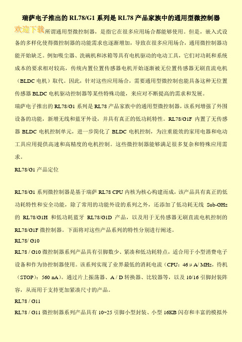
瑞萨电子推出的RL78/G1系列是RL78产品家族中的通用型微控制器所谓通用型微控制器,是指它在很多应用场合都能够使用。
但是,嵌入式设备的多样化使得微控制器的功能需求也逐渐增加,导致在很多应用场合,通用微控制器功能开始缺乏。
例如吸尘器、洗碗机和冰箱等具有电机驱动的电动工具,它们对功耗和系统成本的要求相对较高,传统内置位置传感器电机开始逐渐被无位置传感器无刷直流电机(BLDC电机)取代。
因此,针对这些应用场合,需要通用型微控制也能具备这种无位置传感器BLDC电机驱动控制器等某些特殊功能,来应对不断提高的需求和发展。
瑞萨电子推出的RL78/G1系列是RL78产品家族中的通用型微控制器,该系列增强了外围设备的功能,新增无线和蓝牙外设,并具有真正的低功耗特性。
RL78/G1F内置了无传感器BLDC电机控制单元,进一步简化了BLDC电机控制,为注重能效的家用电器和电动工具应用提供高速和高精度的电机控制。
这些微控制器能够满足很多复杂和特殊应用需求。
RL78/G1产品定位RL78/G1系列微控制器是基于瑞萨RL78 CPU内核为核心构建而成,该产品具有真正的低功耗特性和安全功能,除了常用的功能外设的系列之外,还添加了低功耗无线Sub-GHz 的RL78/G1H和低功耗蓝牙RL78/G1D产品,以及用于无传感器无刷直流电机控制的RL78/G1F微控制器。
下面将对这些产品系列的特性分别进行阐述。
RL78/ G10RL78 / G10微控制器系列产品具有引脚数少、紧凑和低功耗特点,适合用于小型消费电子设备和作为协控制器使用。
该系列实现了业界最低的消耗电流(CPU:46μA/ MHz,待机(STOP):560 nA)。
通过片上振荡器、A / D转换器、比较器等,以及10/16引脚封装阵容,从而用于支持更加紧凑尺寸的产品。
RL78 / G11RL78 / G11微控制器系列产品具有10~25引脚小型封装、小型16KB闪存和丰富的模拟外。
BLDC电机控制算法(瑞萨)

无刷电机属于自換流型(自我方向轉換),因此控制起来更加复杂。
BLDC电机控制要求了解电机进行整流转向的转子位置和机制。
对于闭环速度控制,有两个附加要求,即对于转子速度/或电机电流以及PWM信号进行测量,以控制电机速度功率。
BLDC电机可以根据应用要求采用边排列或中心排列PWM 信号。
大多数应用仅要求速度变化操作,将采用6个独立的边排列PWM信号。
这就提供了最高的分辨率。
如果应用要求服务器定位、能耗制动或动力倒转,推荐使用补充的中心排列PWM信号。
为了感应转子位置,BLD C电机采用霍尔效应传感器来提供绝对定位感应。
这就导致了更多线的使用和更高的成本。
无传感器BLDC控制省去了对于霍尔传感器的需要,而是采用电机的反电动势(电动势)来预测转子位置。
无传感器控制对于像风扇和泵这样的低成本变速应用至关重要。
在采有BLDC电机时,冰箱和空调压缩机也需要无传感器控制。
空载时间的插入和补充大多数BLDC电机不需要互补的PWM、空载时间插入或空载时间补偿。
可能会要求这些特性的BLDC应用仅为高性能BLDC伺服电动机、正弦波激励式BLDC电机、无刷AC、或PC同步电机。
控制算法许多不同的控制算法都被用以提供对于BLDC电机的控制。
典型地,将功率晶体管用作线性稳压器来控制电机电压。
当驱动高功率电机时,这种方法并不实用。
高功率电机必须采用PWM控制,并要求一个微控制器来提供起动和控制功能。
控制算法必须提供下列三项功能:∙用于控制电机速度的PWM电压∙用于对电机进整流换向的机制∙利用反电动势或霍尔传感器来预测转子位置的方法脉冲宽度调制仅用于将可变电压应用到电机绕组。
有效电压与PWM占空度成正比。
当得到适当的整流换向时,BLDC 的扭矩速度特性与一下直流电机相同。
可以用可变电压来控制电机的速度和可变转矩。
功率晶体管的换向实现了定子中的适当绕组,可根据转子位置生成最佳的转矩。
在一个BLDC电机中,MCU必须知道转子的位置并能够在恰当的时间进行整流换向。
瑞萨uPD78F0712的家电风机解决方案.

瑞萨uPD78F0712的家电风机解决方案时间:2011年08月19日中电网字体: 大中小关键词:<"cblue""/search/?q=uPD78F0712"target='_blank'>uPD78F0712<"cblue""/search/?q=家电" target='_blank'>家电<"cblue" "/search/?q=马达控制" target='_blank'>马达控制<"cblue" "/search/?q=瑞萨电子" target='_blank'>瑞萨电子随着科学技术的发展,180°电机控制越来越多在各种领域的应用,尤其在<"cblue" "/search/?q=家电" title="家电">家电领域里。
瑞萨电子目前推出了一系列变频控制专用的8位MCU,本文主要介绍瑞萨电子8位MCU――<"cblue""/search/?q=uPD78F0712"title="uPD78F0712">uPD78F0712的主要特点及基于该MCU的家电风机解决方案。
1. 180°控制的应用场合及特点目前市场上对于家用电器如热水器、油烟机等一般要求其具有低噪声、低损耗、省电节能的特征,因此,类似的这些场合并不适宜使用变频器驱动的交流异步电机,而适合使用小功率无刷直流电机进行调速。
无刷直流电机分为方波控制的BLDC和正弦波控制的PMSM永磁同步电机。
下表是各个电机控制特点比较:表1 电机控制特点由上表可以看出,在小功率电机范围内,180°电机控制具有噪声低、效率高的优点。
瑞萨MCU在汽车仪表及CANLIN应用中的解决方案.

瑞萨MCU在汽车仪表及CAN/LIN应用中的解决方案瑞萨科技于2003年4月由日立制作所和三菱电机的半导体部门合并成立,致力于提供移动通信、汽车电子以及PC/AV(数码家电)领域的半导体解决方案。
在全球汽车半导体市场中,瑞萨占有7.1%的市场份额,排名第四位;在日本市场中占据第一位,市场份额为22.3%。
其汽车半导体解决方案包含了安全、信息、动力总成、底盘以及车身五个方面,其中每个方面都有多种解决方案。
汽车仪表解决方案仪表MCU的特点分以下几个方面:1.内嵌步进电机PWM控瑞萨科技于2003年4月由日立制作所和三菱电机的半导体部门合并成立,致力于提供移动通信、汽车电子以及PC/AV(数码家电)领域的半导体解决方案。
在全球汽车半导体市场中,瑞萨占有7.1%的市场份额,排名第四位;在日本市场中占据第一位,市场份额为22.3%。
其汽车半导体解决方案包含了安全、信息、动力总成、底盘以及车身五个方面,其中每个方面都有多种解决方案。
汽车仪表解决方案仪表MCU的特点分以下几个方面:1. 内嵌步进电机PWM控制器:可直接控制和驱动4-6个步进电机,无需外驱动器IC,因此可以节省成本和布局空间,具有优良的EMI/EMC性能;2. 内嵌LCD控制器:28/32段×4公共引脚,可以直接控制LCD,同样无需外置驱动器IC,因此可以节省成本和布局空间,具有优良的EMI/EMC性能;3. 高速CPU:单指令周期,20 MHz的H8S最小指令执行时间为50ns,而40MHz 的H8SX最小指令执行时间是25ns;4. 强大的定时器:片上16位定时器脉冲单元有三个16位定时器通道,包括输入捕捉、输出比较、PWM和相位计算。
H8S/228X特殊模块的基本功能,包括三个部分:定时器脉冲单元(TPU);步进电机PWM控制器和LCD控制器。
TPU是由3个16位定时器通道组成,包括最多8个脉冲输入/输出,可以为每个通道设置:比较匹配的波形输出;输入捕捉功能;计数器清零操作;同步运行;定时器计数器能够同时写入;可以比较匹配与输入捕捉同时清零;利用同步计数器操作实现寄存器同时输入/输出;与同步运行结合的最大7相位PWM输出。
瑞萨新型100kW级逆变器解决方案实现业界领先的3.9升小型设计等级
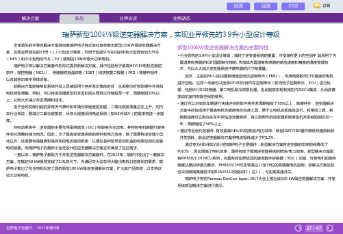
全球领先的半导体解决方案供应商瑞萨电子株式会社宣布推出新型100kW级逆变器解决方案,实现业界领先的3.9升(L)小型设计等级,可用于包括SUV在内的中到大型混合动力汽车(HEV)和中小型电动汽车(EV)使用的100kW级大功率电机。
瑞萨电子将以解决方案套件的形式提供新解决方案,其中包括用于提高HEV/EV电机性能的软件,微控制器(MCU)、绝缘栅双极晶体管(IGBT)和快恢复二极管(FRD)等硬件组件,以及其他功率半导体设备。
新解决方案能够帮助系统开发人员缩短用于各开发步骤的时间:从规格分析到软硬件开发和电机特性调整。
例如,可以将逆变器原型机开发时间从两到三年缩短至一年,周期缩短50%以上,从而大大减少开发周期和成本。
由于全球变暖引起的异常天气事件和环境污染程度的加剧,二氧化碳排放量正在上升。
对汽车行业来说,要减少二氧化碳排放,尽快大规模采用电动系统(如HEV和EV)的需求将进一步提高。
在电动系统中,逆变器的主要作用是将直流(DC)电转换为交流电,并控制电机根据行驶条件变化调整转速与电流。
因此,为了提高逆变器系统的燃料和电力效率,除了需要将逆变器小型化以外,还需要有高精度和高效率的电机驱动系统,以便在各种型号发动机室的有限空间内安装电动装置。
而瑞萨电子的最新小型化设计的逆变器解决方案正好满足了这些需求。
一直以来,瑞萨电子都致力于开发逆变器解决方案套件。
在2014年,瑞萨开发出了一套解决方案,在额定50 kW级别实现了2.9L的尺寸。
为满足对大型车用大输出电机日益增长的需求,瑞萨电子推出了包含电机标定工具的新型100 kW级逆变器解决方案,扩大其产品阵容,以支持这些大功率电机。
新型100kW级逆变器解决方案的主要特性•行业领先的3.9升小型设计等级,减轻了逆变器系统的重量,可安装在更小的空间中其采用了内置温度传感器的IGBT晶圆制作模组. 凭借其内置温度传感器的响应速度和精度的温度管理技术,可以大大减少逆变器系统中散热器的尺寸和重量。
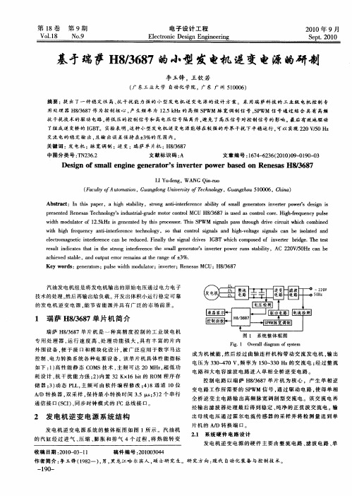
基矛瑞萨H8/3687的小型发电机逆变电源的研制
Vo .8 11 No9 .
电 子 设 计 工 程
E e to i e in En ie rn lcr nc D sg gn eig
21 0 0年 9月
S p .2 0 e t 01
基矛瑞萨 H8 67的小型 发电机 逆变电源的研制 /8 3
李玉锋 , 王钦 若
Ab t a t n ti a e , a h g t b l y s o g a t i tr r n e a i t f s l g n r tr n e tr p w r e in i sr c :I h s p p r i h sa i t , t n n i n e e e c bl y o ma l e e ao s i v re o e ' d sg s i r - f i s p e e td R n s sT c n lg ’ i d sr lg a e mo o o t lMC /6 7 i u e s c n rlc r . g -r q e c u s r s n e e e a e h oo yS n u t a —r d t rc n r U H8 8 s s d a o t o e Hih f u n y p l i o 3 o e e
e e t ma e i n e e e c a e r d c d F n l h i a rv s GB i h c mp s d o iv re b d e T e ts l cr o g t it r r n e c n b e u e . i al t e sg ld e I T wh c o o e f n et r r g . h e t n c f y n i i r s l id c t s t a n t e sr n n e e e c h mal g n r tr n e e o r r n tb l y,AC 2 0 / 0 a e e u t n ia e h t i h t g it r r n e t e s l e e ao ' i v r r p we u s s i t o f s t a i 2 V 5 Hz c n b a h e e t b e n u p t ro e i sa e r n e o ± % . c iv d sa l .a d o t u r rr man t h a g f 3 e t Ke r s e ea os u s i t d ltr n e e ;R n s s MCU;H8 3 8 y wo d :g n r tr ;p le w d h mo u ao ;iv r r e e a t ,6 7
瑞萨借SuperH系列在电机控制领域表现优异.

瑞萨借SuperH系列在电机控制领域表现优异瑞萨借SuperH系列在电机近年来,瑞萨科技在电机控制应用方面不断取得卓著成绩。
尤其在AC伺服器和通用变频器等工业设备和高级家电的应用中,SuperH族产品作为瑞萨的高端MCU,其优势已得到广泛认可,同时也取得了越来越大的市场份额。
节能在目前全球节能需求日益高涨的背景下,为了更为有效地利用从冰箱、洗衣机等家电产品,到工业机器人、各种制造设备等工业产品,现今中小型电机的应用范围非常广泛。
在使用的电机种类上,则包括有刷DC电机和步进电机、无刷DC电机(PMSM)、单相异步电机、三相同步电机等。
同时,还存在PWM调制和矢量控制等与各种电机相对应的控制算法。
为了满足节能的需求,电机控制正朝着更高级、更精密、响应性更快的方向发展。
丰富的电机控制用MCU产品线所谓高级精密的电机控制,即使用MCU进行的控制。
根据目标控制量和在这一需求背景下,为了能够对应各种应用、各种电机、各种控制法,瑞萨在电机控制用MCU产品线上则拥有SuperH、M16C、H8、R8C等各产品群。
特别是在多轴切削适用于工业应用和高档家电SuperH族在电机控制方面的具体应用包括建筑机械、食品加工机械、输送机械、印刷机械等的通用变频器,以及应用于FA领域的输送装置和注塑成型机等的AC伺服器。
此外,在家电产品方面,则可用于空调的室外机和冰箱 (压缩机)、洗衣机 (无刷DC电机和热泵压缩机控制)等高端产品。
以SH-2及SH-2A为核心的产品推广用于电机控制的SuperH族MCU,主要以搭载了SH-2A或SH-2内核的产品群为主。
例如SH-2A内核,在采用超标量体系结构可同时执行2条指令之外,更实现了寄存器组的新型搭载,使中断响应时间得到缩短,大幅提高了实时性能。
可谓是最适合于有高度响应性要求的控制用途CPU内核。
此外,为满足电机控制的需要,SH-2A还同时具有多功能的定时器和高速高分辨率的A/D、D/A变换器等外围功能。
BLDC电机控制算法

BLDC电机控制算法BLDC(Brushless DC)电机是一种无刷直流电机,常用于工业和家用设备中。
它的控制算法起着至关重要的作用,可以决定电机的性能和稳定性。
下面将介绍一种基于瑞萨(Renesas)控制器的BLDC电机控制算法。
1.确定电机转速:从编码器或霍尔传感器中获取电机转速信息。
这个转速信息将用于后续步骤中的PWM(脉宽调制)控制。
2.确定电机位置:使用编码器或霍尔传感器确定电机的位置信息。
这个位置信息是电机控制的关键,因为它决定了电机相位的换向时间。
3.确定换向时机:根据电机的位置信息,确定下一个换向时机。
换向时机是指改变相位电流的时间点,以使转子保持在正确的位置。
这一步需要根据电机模型和性能要求进行计算。
4.设置相位电流:根据换向时机,确定要流经每个相位的电流大小和方向。
这一步需要通过PWM控制来实现。
PWM控制的原理是调整电流的开关时间和占空比,以实现所需的相位电流。
5.更新PWM控制:根据当前位置和期望电流,通过调整PWM控制算法中的参数,实现更准确的电流控制。
这可以通过PID(比例-积分-微分)控制器来实现,根据实际情况进行参数调整。
6.控制电机转速:通过调整相位电流和PWM控制算法中的参数,实现所需的电机转速和运动控制。
这可以通过增加或减少电流或调整换向时机来实现。
7.监控电机状态:通过传感器对电机的状态进行监测,包括电流、转速和温度,以确保电机正常工作和保护。
如果电机发生故障或超过安全工作范围,则应采取相应的措施,如停机或报警。
总结起来,BLDC电机控制算法的主要步骤包括获取转速和位置信息、确定换向时机、设置相位电流、更新PWM控制、控制电机转速和监控电机状态。
通过合理设计和实现这些步骤,可以实现BLDC电机的稳定、高效和精准控制。
瑞萨电子MCU直流无刷电动工具解决方案

RL78 内核 RL78 内核 结合 78K 与 R8C 结合78K与R8C先进功能的 先进功能的
7 7外部 外部/24 /24内部 内部
结合 与 先进功能的 结合78K 78K 与R8C R8C 先进功能的 新一代 MCU 内核 新一代 MCU 内核 新一代 新一代MCU MCU内核 内核
A/D A/D转换器 转换器 A/D 转换器 A/D 转换器 8 x 10 8x 10位 位
8 8x x 10 10位 位
通讯接口 通讯接口 通信接口 通信接口 5 5通道串行接口:可配置 通道串行接口:可配置
5 5通道串行接口:可配置 通道串行接口:可配置 为 为CSI CSI、 、UART UART与 与I2C I2C 为 为CSI CSI、 、UART UART与 与I2C I2C
片上高速振荡器 片上高速振荡器 片上高速振荡器 片上高速振荡器 频率可配置,最高达 频率可配置,最高达
频率可配置,最高达 频率可配置,最高达 64MHz 64MHz 64MHz 64MHz
Flash Flash 64KB 64KB Flash 64KB Flash 64KB RAM RAM 5.5KB 5.5KB RAM RAM 5.5KB 5.5KB Data Data Flash Flash 4KB 4KB Data Data Flash Flash 4KB 4KB
3
© 2011 Renesas Electronics (China) Co., Ltd. All rights reserved.
参考设计特点
转动速度档位设置、过流保护、过热保护、工作状态LED显示 速度最高达2400转/分 小尺寸PCB与低成本 锂电池供电
4
© 2011 Renesas Electronics (China) Co., Ltd. All rights reserved.
HEV_EV inverter solution
High speed and low power consumption by the micro isolator technology with the built-in driver IC
HEV/EV Inverter Solution
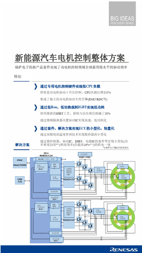
Renesas new kit solution enabling dual-motor control to achieve the best-in-class driving efficiency
Features
Solutions
Low CPU load by dedicated motor control hardware
3% CPU load even in the dual-motor drive & voltage boost control
Dedicated hardware engine (EMU/RDC) enabling the independent dual-motor drive
Low power consumption by IGBT with low Ron and less switching losses
生成 矩形波
内置微 频隔离
器的驱 动IC
功率器件
电流 传感器
电机1
角度 传感器
电机
矢量控制 (EMU)
电流检测
角度检测 (RDC)
PW M输 出
生成 矩形波
内置微 频隔离
器的驱 动IC
电流 传感器
电机2
角度 传感器
电流检测
新能源汽车核心部件--电控IGBT模块入门详解,从小白到精通

根据乘联会数据,2022年6月新能源车国内零售渗透率27.4%,并且2022年6月29日欧盟对外宣布,欧盟27个成员国已经初步达成一致,欧洲将于2035年禁售燃油车。
市场越来越景气,同时国内近期新发布的新能源车型也百花齐放。
不论是普通消费者、新能源汽车产业相关从业者,还是一二级市场投资人,也逐渐深入关注研究新能源车的一些核心部件,尤其是功率器件IGBT模块,今天小编就用问答的形式给大家展开讲讲,希望能够用比较通俗的解释帮助到大家。
电驱系统和IGBT模块的作用要弄明白IGBT模块,就要先了解新能源汽车的电驱系统,先用一句话概括电驱系统如何工作:在驾驶新能源汽车时,电机控制器把动力电池放出的直流电(DC)变为交流电(AC)(这个过程即逆变),让驱动电机工作,电机将电能转换成机械能,再通过传动系统(主要是减速器)让汽车的轮子跑起来。
反过来,把车轮的机械能转换存储到电池的过程就是动能回收。
1、什么是“三电系统”和“电驱系统”?三电系统,即动力电池(简称电池)、驱动电机(简称电机)、电机控制器(简称电控),也被人们成为三大件,加起来约占新能源车总成本的70%以上,是决定整车运动性能核心的组件。
电驱系统,我们一般简单把电机、电控、减速器,合称为电驱系统。
但严格定义上讲,根据进精电动招股说明书,电驱动系统包括三大总成:驱动电机总成(将动力电池的电能转化为旋转的机械能,是输出动力的来源)、控制器总成(基于功率半导体的硬件及软件设计,对驱动电机的工作状态进行实时控制,并持续丰富其他控制功能)、传动总成(通过齿轮组降低输出转速提高输出扭矩,以保证电驱动系统持续运行在高效区间)。
图:电驱系统示意图图片来源:进精电动招股说明书2、什么是“多合一电驱系统”?一开始电机、电控、减速器都是各自独立的零部件,但随着技术的进步,我们把这三个部分集合在一起做成一个部件,就变成了“三合一电驱”。
集成的目的主要是节省空间、降低重量、提升性能、降低成本。
瑞萨PMSM电机位置控制
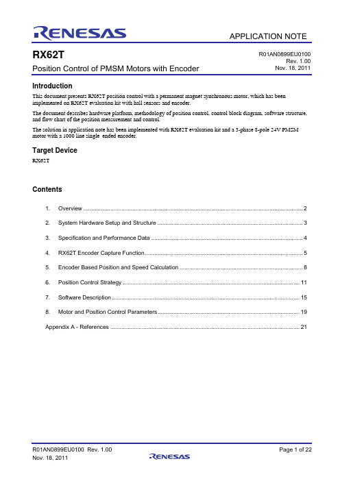
APPLICATIONNOTE RX62T R01AN0899EU0100Rev. 1.00Position Control of PMSM Motors with EncoderNov. 18, 2011IntroductionThis document presents RX62T position control with a permanent magnet synchronous motor, which has beenimplemented on RX62T evaluation kit with hall sensors and encoder.The document describes hardware platform, methodology of position control, control block diagram, software structure,and flow chart of the position measurement and control.The solution in application note has been implemented with RX62T evaluation kit and a 3-phase 8-pole 24V PMSMmotor with a 1000 line single–ended encoder.Target DeviceRX62TContents1.Overview (2)2.System Hardware Setup and Structure (3)3.Specification and Performance Data (4)4.RX62T Encoder Capture Function (5)5.Encoder Based Position and Speed Calculation (8)6.Position Control Strategy (11)7.Software Description (15)8.Motor and Position Control Parameters (19)Appendix A - References (21)1. OverviewPosition control plays an important role in various areas such as automation industry, semiconductor industry, etc. Permanent magnet synchronous motors (PMSM) are ideal for advanced position control systems for their potentials of high efficiency, high torque to current ratio, and low inertia, have been widely used in the industrial fields. Various approaches have been made to realize high performance motion control.With successively improving reliability and performance of digital controllers, advances in Microprocessors (MCU) have greatly enhanced the potential of PMSM in servo position control applications. Digital control can be implemented by MCUs, which make it superior to analog based stepper control, since the controller is much more compact, reliable, and flexible. High performance of PMSM can be obtained by means of field oriented control, which is only realizable in a digital based system.RX62T is a 32-bit high-performance microcontroller with a maximum operating frequency of 100MHz and 165 DMIPS and single precision floating-point unit (FPU), which is equipped with multifunction timers (MTU, GPT), high-speed 12-bit A/D converter and encoder signal capture for facilitating servo motion control.In this application note, a RX62T floating point unit (FPU) based position motion control system is proposed. Position regulation is developed to provide both a trajectory generator and a PID controller, which ensures accurate position control and fast tracking. The trajectory generator provides position set-point commands. The position PID controller operates on the position error and outputs a current command. The current regulation with field oriented control is implemented to secure fast dynamic response.Software developed is applicable to following devices and platforms.MCU: RX62T and RX62NMotor: three-phase permanent magnetic synchronous motors (PMSM)Platform: Renesas RX62T demo kitControl algorithm: Encoder based position control2. System Hardware Setup and StructureRX62T FPU based position control is implemented with Renesas RX62T evaluation kit and a three-phase PMSM motor with a1000 line single-ended encoder as shown in Figure 1.RX62T evaluation kit is a single board inverter, based on the RX series microcontroller RX62T.A complete 3-phase inverter on-board with a low voltage motor24Vexternal power supply to provide DC bus voltage, 15V and 5V power supplyPower devices use Renesas low voltage MOSFETsPower rate up to 120wattsSupport 3 shunt and single shunt current measurementEasily jumper change from the external amplifiers to the internal PGAUSB communication with the PC via a H8S2212 MCUUser GUI to modify motor and control parameters, tune both speed and position controlConnectors for hall sensors and encoder connectionsLCD display to monitor the operation statusSupport the standalone mode set by potentiometer and push buttonsSupport the second motor drive, signals and connector for another motor control power stage are available The motor is a 24V 4 pair poles 3-phase permanent magnetic synchronous motor with3 hall sensors1000 line quadrature encoderFigure 1 System hardware setup (motor and control platform)3. Specification and Performance DataThe implementation of position control is based on Renesas evaluation kit and RX62T MCU, the main specification data are described as following:Input voltage: 24VDCRated bus voltage: 24VOutput voltage: 24VACRated output power: 120WPWM Switch frequency: 20KHzControl loop frequency: 10KHzCurrent measurement: 3 shunt resistorsPosition measurement: 1000 line quadrature encoderImplementation: FPUCPU bandwidth: 17%Used flash memory: 13.444KbytesUsed RAM: 1.725KbytesUsed stack : 336bytes4. RX62T Encoder Capture FunctionThe RX62T is a 32-bit high-performance microcontroller with a maximum operating frequency of 100MHz and 165 DMIPS and single precision floating-point unit (FPU), which is equipped with multifunction timers (MTU, GPT), high-speed 12-bit A/D converter, and 10-bit A/D converter for facilitating motor control. Figure 2 shows the block diagram of a senorless vector control of PMSM motors based on the Renesas RX62T Microcontroller.RX62T has a dedicate function for the encoder measurement as depicted in Figure 2. MTU3 timer external clock input TCLKA, TCLKB, TCLKC, and TCLKD can be used for two-phase encoder pulse inputs. When the MTU3 timer of Channels 1 and 2 are specified by the phase counting mode, an external encoder clock is selected as the counter input clock and TCNT operates as an up/down-counter. The phase difference between two external input clocks is detected and TCNT is incremented or decremented accordingly. The rotor position and speed can be measured by reading the TCNT counts.The following summarizes the MTU3 function for the encoder pulse counting functionality:MTU Channel 1 & 2 support 2-phase pulse counting mode which is called “Phase Counting Mode”This function covers 4 modesAt these modes, the counter works as up/down counter. And it is possible to detect the direction of counter with the flag.Up/down count by detecting phase difference between phase A and B of encoder on mode1 and mode 4 o Mode 1: every rising edge & falling edge of both of encoder pulseo Mode 4: every rising edge & falling edge of phase B encoder plusesUp/down count by two pulse lines which indicate the direction, speed and position.o Mode 2: One pulse line and One directiono Mode 3: Two pulse lines for each directionMTU can detect automatically speed and position data as the pulse width & the pulse. The data of speed and position can be captured every periodic cycle.In this application, the encoder pulse A and B are input to the TCLKA and TCLKB. The Z pulse is to IRQ0. For the second motor, the encoder pulse A and B are input to the TCLKC and TCLKD. The Z pulse is to IRQ3.The host communication using the graphic user interface (GUI) is communicated with the RX62T MCU by the USB communication. It can display the motor operation status in the real time, tune the motor and control parameters, and drive the motor for both speed control and position control.Figure 2 RX62T encoder capture functionalityTable 1 lists the timer register function for Channel 0 to 2 for the encoder capture. The timer MTU enable to automatically detect both the pulse width and the number of pulse of encoder every speed control loop period. It is not necessary of external wiring for any trigger signals. The encoder signals are directly input to Timer external clock; TCLKA and TCLKB as clock source of channel, and also, input command pulse to Timer external clock; TCLKC and TCLKD as clock source of Channel 2.Channel 1 counter is counted by every falling edge and rising edge of encoder pulse.Channel 0 is used for interval time to generate input capture trigger of Channel 1 and Channel 2, and interrupt of speed control loop.Channel 2 measures pulse command input.Channel 0 compare match (speed control loop period) can be selected as input capture trigger for Channel 1 internally.Channel 1 and Channel 2 external timer clock (encoder pulse or command pulse) can be selected as input capture trigger for Channel 0 internally.Table 1 MTU timer registers functionFigure 3 shows how the MTU captures the encoder signals in phase counting mode. The Channel 1 is coupled with Channel 0 to input 2-phase encoder pulses of a servo motor in order to detect position or speed. Channel 1 is set to phase counting mode 1, and the encoder pulse A-phase and B-phase are input to MTCLKA and MTCLKB. In Channel 0, MTU3_0.TGRC compare match is specified as the TCNT clearing source and MTU3_0.TGRA and MTU3_0.TGRC are used for the compare match function and are set with the speed control cycle and position control cycle. MTU3_0.TGRB is used for input capture, with MTU3_0.TGRB and MTU3_0.TGRD operating in buffer mode. The Channel 1 counter input clock is designated as the MTU3_0.TGRB input capture source, and the widths of 2-phase encoder 4-multiplication pulses are detected. MTU3_1.TGRA and MTU3_1.TGRB for Channel 1 are designated for the input capture function and MTU3_0.TGRA and MTU3_0.TGRC compare matches in Channel 0 are selected as the input capture sources to store the up/down-counter values for the control cycles.Therefore, the RX62T MTU itself can realize precise detection of the pulse width and the number of pulses,which are needed to estimate motor speed and position. It doesn’t need the load of the CPU hardly to detectthose. Also the MTU is able to receive the pulse command as well.Figure 3 Encoder pulse capture in phase counting mode5. Encoder Based Position and Speed Calculation5.1 Position and Speed MeasurementA digital encoder outputs three pulse trains: A,B and Z, as shown in Figure 4. These pulses are fed into a timer unit TCLKA and TCLKB that counts events. Pulses A and B are offset by 1/4th of the distance to give a 90-degree offset, so they are known as quadrature counts. Pulse Z occurs only once per rotation. It is fed into the interrupt input (IRQ0) and zeroes out (resets) the counter MTU2_TCNT. When the pulse Z occurs, the rotor angle with respect to the stator frame produces a definite value, preferably zero. If this value is not zero, it is a constant offset that can be measured. Quadrature counters are designed to count these pulses up or down, depending on whether A comes before or after B. That is, the relationship between A and B indicates the direction of rotation.Figure 4 Relationship among the digital encoder pulses A, B and ZThe encoder has been aligned and calibrated with Hall sensor U with zero initial position. The angle is zero count when the Z pulse occurs through the external interrupt IRQ0. From this point onwards it is given a certain count value as the quadrature counter is read. As shown in Figure 5, the phase counting mode 1 is used to up/down count by detecting phase difference between A and B phase. These counts are transformed into a proper angle value for the rotor position.Figure 5 Encoder counting mode operationMotor speed determines how much the angle of the rotor changes over time. As shown in Figure 6, pulses A and B from the encoder are used at the control loop rate. Two angles are measured at constant time intervals, thus giving the measurements needed to compute speed: delta angle and delta time. Speed is computed by dividing the delta angleθΔby the delta time.The motor position is the number of the encoder pulse as N(m)-N(m).θΔ = N(m+1) – N(m)and the motor speed isω = (N(m+1)-N(m)) /TsprFigure 6 Speed calculation using encoder pulses A and B at control loop rate5.2 Initial Position IdentificationIncremental encoders can only give displacements from the initial position and can’t provide absolute position. For PMSM motor and position control, the initial position is required. Although alignment has been calibrated, the initial starting position before the Z pulse is still unknown.By means of Hall sensors the rotor initial position can be identified, and further corrected when the rotor starts rotating. Assuming the Hall sensors are located at each phase, as shown in Figure7. The output signals of the Hall sensors are illustrated in Figure 8. It can be seen that the resolution of the Hall sensor signals are 60° (electrical degree). Table 1 shows the possible combinations corresponding to different positions.Figure 7 Hall sensors for initial rotor positionFrom Figure 8 and Table 2, given a specific Hall sensor output combination, the rotor must reside in certain section with a range of 60°. The initial position is determined as follows. When a group of output signals are obtained, for example, (101), we can decide which section the rotor is in (section 1 in this example). We can set the initial position at the center of the section (30° in this example). It can be seen that the maximum error of the initial position is 30°, which occurs when the rotor is at the edge of two regions. However, even with 30° error, the motor is still able to produce sufficient torque to start the motor.Once the motor starts rotating, the position can be readily corrected when the rotor moves out of the initial region and enters the next section. This position is accurate. In the previous example, when the motor starts rotating in the positive direction from section 1, the rotor position can be corrected when the position is 60°.Table 2 Relationship between hall sensors and rotor position Section Hu Hv Hw RotorPosition1 1 0 1 0~602 1 0 0 60~1203 1 1 0 120~1804 0 1 0 180~2405 0 1 1 240~3006 0 0 1 300~360Figure 8 Hall sensor output signals6. Position Control Strategy6.1 Block Diagram of Position ControlFigure 9 is block diagram of position control. The position control developed includes two loops. The outer loop is position control to make the motor tracking and holding the given position. The inner loop is current control. Actually it is the torque control loop. The motor currents are sampled through three shunt resistors and converted into the dq axis currents. The control loop here is to control the q axis current for the torque.Figure 9 Block diagram of position controlThe position control scheme of the PMSM is illustrated in Figure10. The system has an inner loop of current regulation using vector control, and an outer loop of position regulation. This dual-loop structure ensures the fast torque response by using the vector control, high position accuracy and fast tracking performance with the position controller.In order to determine the d and q axis currents, the phase currents must be measured. Vector formulation uses Clarke and Park transforms to convert the measured phase currents from the (u, v, w) frame to first transform them in the static orthogonal (a,ß) frame (which is 90 degrees apart), and then, to the rotor frame which is also an orthogonal frame aligned along the magnetic field axes known as the (d,q) frame. These transformations use the transcendental functions sine and cosine of the rotor angle; thus, it is a requirement that the rotor angle is known at the time the calculation is made. The position control requires current sensors, plus an encoder attached to the rotor shaft to measure the rotor position.Once the currents are transformed in the (d,q) frame, the control algorithm simply runs the PID or PI loop to calculate the required voltages for the torque and flux. These required voltages (Vdc, Vqc) are then transformed back in the (u, v, w) frame using the inverse Clarke and inverse Park transforms to further calculate the PWM duty cycle.The position command is an input to the position control system. The motor has an encoder mounted on its rotor to give the quadrature pulses A and B, as well as the zero synch pulse Z. All three of the rotor position signals are sent to the MCU’s input-capture and timer/quadrature counter peripheral for making position and speed measurements. The commanded position compares with the actual rotor position. The position regulator uses the traditional PID controller, and outputs the torque control command of iq* to make the motor moving and tracking the commanded position.Figure 10 Position control scheme diagram6.2 Position Control Loop DesignThe basic components of a typical servo position control system are depicted in Figure11. In this figure, the servo position control closes a current loop as described in next section and is modeled simply as a linear transfer function Gireg(s). Of course the servo drive has peak current limits, so this linear model is not entirely accurate; however it does provide a reasonable representation for analysis. For the purposes of this discussion the transfer function of the current regulator or really the torque regulator can be approximated as unity for the relatively lower motion frequencies.Figure 11 Position PID controller topologyThe PMSM motor is modeled as a lump inertia J, a viscous damping term B, and a torque constant Kt. The lump inertia term is comprised of both the servomotor and load inertia. It is also assumed that the load is rigidly coupled such that the torsional rigidity moves the natural mechanical resonance point well out beyond the position controller’s bandwidth. Thisassumption allows us to model the total system inertia as the sum of the motor and load inertia for the frequencies that can be controlled.An encoder coupled directly to the motor shaft measures the actual motor position θ(s). External shaft torquedisturbances Td are added to the torque generated by the motor's current to give the torque available to accelerate the total inertia J.Around the current regulator, motor block is the servo position controller that closes the position loop. The basic servo position controller provides both a trajectory generator and a PID controller. The trajectory generator provides only position set-point commands labeled in Figure 9 as θ*(s). The PID controller operates on the position error and outputs a current command.There are three gains to adjust in the PID controller, Kp, Ki and Kd. These gains all act on the position error defined as:)()(*s s θθθ−=ΔNote the superscript “*” refers to a commanded value.The output of the PID is given mathematically in the time domain as:)()()()(*t dtdK dt t K t K t iq di p θθθΔ+Δ−Δ=∫ Loosely speaking, the proportional term affects the overall response of the system to a position error. The integral term is needed to force the steady state position error to zero for a constant position command and the derivative term is needed to provide a damping action, as the response becomes oscillatory. Unfortunately all three parameters are inter-related so that by adjusting one parameter will affect any of a previous parameter adjustment.Tuning the PID controller can be done if the motor and load parameters are known and the desired frequency response are known. They are adjusted using the following parameters in the header file of “customize.h”.6.3 Current Control LoopThe current loop is a standard PI type based on the standard Park-Clarke stationary reference frame to rotary reference transformations. The initial rotor position is determined by use of the Hall sensors. Once a Hall transition occurs, the rotor position is then determined by reading the incremental encoder. The basic block diagram for the current vector control is shown in Figure 12.Figure 12 Block diagram of current vector controlNeglecting motor saliency, the commanded q axis current, iq* is linearly related to the commanded torque. The “d” axis current command, id* is set to zero as field weakening is not required. The transformation takes two steps. First, the stationary currents are transformed to an arbitrary stationary pair of orthogonal axes α, β and second, the axes are then rotated to the rotor axes for control purposes.The typical current PI controller is depicted in Figure 13. Kp and Ki are the proportional gain and integration gain, respectively, which can be adjusted by the software. The hardware gain Kb takes into account the bus voltage.Figure 13 Current PI controller topologyThe transfer function of the block diagram is:⎟⎠⎞⎜⎝⎛+⎟⎟⎠⎞⎜⎜⎝⎛++⎟⎠⎞⎜⎝⎛+⎟⎟⎠⎞⎜⎜⎝⎛=LK K s L R K K s L K K s L K K s i s i bi b p b i b p 2*)()(It has a characteristic equation in the form of:022002=++ωξωs sTherefore:bp K RL K −=02ξωbi K LK 20ω=The system exhibits the standard second order response with the addition of a real zero. To tune the system, the high frequency of 500Hz needs to be first set for Kp, and then slowly increase the integral term Ki to bring our steady state error to zero.7. Software Description7.1 Overall Software StructurePosition control algorithm is implemented with the complete C code using Renesas’ RX62T MCU floating point unit. The overall software structure is shown in Figure 14.Figure 14 Position software architectureThe procedures include:initializations of RX62T MCU, motor and control parameterscurrent offsets calculationbus voltage and phase currents measurementshall sensor and encoder readinginitial position identificationrotor position calculationvector control transformationmotion profile - trajectory generationposition regulatorcurrent controllersPWM duty calculationspace vector PWM generation7.2 Software HEW WorkspaceShown in Figure 15 is the workspace for position control using Renesas’ HEW compiler.All codes are written in the floating point C language;The software is modularized according to the position control block diagram (as shown in Figure10);I/O definitions and basic MCU drivers are automatically generated by HEW;Motor and control parameters are easily tuned through a header file of “customize.h” and GUI user interface. The codes include dbsct.c; hwsetup.c, intprg.c; main.c; mcrplibf.c; motorcontrol.c; resetprg.c; userif.c and vectbl.c.dbsct.c includes structures used by the runtime library both to clear un-initialized global variables and to write initial values into initialized global variable sections.hwsetup.c is hardware initializations.vecttbl.c contains the array of addresses of ISRs.resetpr.c has functions called just after reset.intprg.c is entry points for all of standard ISRs vectors.main.c including: initialization of control parameters, MTU3 timer, interrupts, serial communication, encoder capture definitions; and uploading eeprom parameters. The current sensor offsets are calculated before theoutput of PWMs. The while loop executes parameter update and SCI communication with graphic user interface.The motorcontrol.c is a major code for position control, which contains most of functions and function calls to implement position control.Mcrplibf.c mainly includes vector control transformations – Clarke, Park, and inverse Clarke and Park transformations, and sine and space vector PWM generation.Figure 15 Encoder counting mode operation position control software workspace7.3 Hall and Encoder Based Position and Speed MeasurementFigure 16 is a flowchart of position measurement. The procedures for the position measurement based on hall sensors and encoder are:Initialize hall sensor and encoder capture timer registers and I/O ports;Identify the rotor initial position using hall sensor;Move the motor to capture the position using encoder pulses;Calibrate the rotor position once the hall commutation changes;After calibration, recalculate the rotor position;Check encoder Z pulse and reset the position offset and encoder pulse capture timer count;Calculate the rotor position and motor speed.Figure 16 Encoder counting mode operation Flowchart of position and speed measurement7.4 PWM Interrupt for Position ControlThe position profile generation and position control are put in the PWM interrupt with 16 kHz carrier frequency. Figure 17 is a flowchart of PWM interrupt.The procedures in the PWM interrupt of MC_ConInt () are:Measure motor phase motor currents and DC bus voltage;Calculate motor position and speed using hall sensors and encoder;Transfer motor currents into dq currents;Current control loop;Update trajectory generator and position profile;Position control loop;PWM generation using space vector PWM modulation or sinusoidal PWM modulation.Figure 17 Flowchart of PWM interrupt for position control8. Motor and Position Control Parameters8.1 Tuning through header fileAccording to the motor data sheet and position control requirements, motor and control parameters, and motion profile should be properly tuned.Motor and control parameters required in the code of “customize.h” include:#define ENC_EDGES_CUSTOM 4000 // total encoder Edges/Revolution#define PWM_FREQ_CUSTOM 16000 // PWM Frequency in Hz#define SAM_FREQ_CUSTOM 16000 // Sample Frequency in Hz#define C_POLI_CUSTOM 4 // polar couples number#define R_STA_CUSTOM 8 // stator phase resistance in Ohm/OHM_DIV#define L_SYN_CUSTOM 10 // synchronous inductance in Henry/HEN_DIV#define POS_MIN_CUSTOM 0 // minimum position in counts#define POS_MAX_CUSTOM 40000 // maximum position in counts#define KP_CUR_CUSTOM 60 // K prop. current control#define KI_CUR_CUSTOM 80 // K integ. current control#define K_P_POSITION 10 // K prop. position control#define K_I_POSITION 12 // K integ. position control#define K_D_POSITION 150 // K derivative psotion control8.2 Operation through GUIThe motor and control parameters can be tuned through Renesas friendly graphic user interface as shown in Figure 18. Without modifying the code, the parameters can be set for the different motors and applications. There is a parameter window to set up 20 parameters. Scrolling up and down through these parameters, the user can make changes to the settings, and “Write” to EEPROM, but this doesn’t change the “customize.h” file. The original values will be restored upon RESET. From Figure 19, it can be seen that these parameters mirror the #defines in the “customize.h” file. The motor and control parameters can be easily changed by the GUI.In the meantime, the GUI has position control window to set the commanded position, and display the motor actual operation status.Figure 18 GUI interface of evaluation kitFigure 19 Parameter windowAppendix A - References1.RX62T Group User’s Manual: Hardware, R01UH0034EJ0110, April 20, 20112.DevCon 2010 Courses:ID-620C, Complete Motor Control Integration with RX62T.ID 623C, Understanding Sensor-less Vector Control with Floating Point Unit (FPU) Implementation.3.DevCon 2008 Courses:ID-504, Speed Control using a Digital Encoder and Vector Formulation4.Application Note of Sensorless Vector Control of three-phase PMSM motors, REU05B0103-0100/Rev.1.00,March, 20095.Application Note of Mcrp05: Brushless AC Motor Reference Platform, REU05B0051-0100, Feb, 2009Website and SupportRenesas Electronics Website/Inquiries/inquiryAll trademarks and registered trademarks are the property of their respective owners.Revision RecordDescriptionRev. Date Page Summary 1.00 Nov. 18, 2011. — First edition issuedGeneral Precautions in the Handling of MPU/MCU ProductsThe following usage notes are applicable to all MPU/MCU products from Renesas. For detailed usage notes on the products covered by this manual, refer to the relevant sections of the manual. If the descriptions under General Precautions in the Handling of MPU/MCU Products and in the body of the manual differ from each other, the description in the body of the manual takes precedence.。
CEVA发布全新通用混合DSP控制器架构CEVABX
敬请登录网站在线投稿2019年第3期95i V i s i o n1000X系列所自带的先进测量和分析功能㊂这些培训信号还可与免费的教育培训套件结合使用;培训套件中包含了全面的示波器实验室指南,以及示波器基础知识的幻灯片㊂瑞萨电子电机故障检测e A I解决方案简化家用电器维护瑞萨电子株式会社推出针对家用电器电机控制的e A I故障检测解决方案㊂该方案采用瑞萨电子R X66T32位微控制器(M C U),基于嵌入式人工智能(e A I),可检测冰箱㊁空调㊁洗衣机等家电因电机异常而发生的故障㊂直接利用可显示电机状态的属性数据(如电流或转速),无需增加传感器,即可用单个M C U实现电机控制及基于e A I的异常情况检测㊂通过基于e A I和针对电机控制的故障检测手段,检测的结果不仅可用于在故障发生时触发警报,还可用于进行预防性维护 例如,e A I可预判需要进行修复和维护的时间点,以及准确定位故障出现的位置㊂在产品发生问题前预测故障这一新功能,将有效提升家电制造商的维护效率及产品安全性㊂S i l i c o n L a b s蓝牙M e s h技术应用于智能家居产品S i l i c o n L a b s宣布其蓝牙M e s h技术被小米(01810.H K)选中,用于该公司近日发布的智能家居产品中㊂此次由小米生态链公司生产且采用S i l i c o n L a b s蓝牙M e s h 技术的产品 涵盖智能球泡㊁智能烛泡㊁智能筒灯和智能射灯等智能照明产品,它们均可通过蓝牙M e s h网络由小爱智能闹钟等设备进行控制㊂新的智能光源产品采用S i l i c o n L a b s运行蓝牙M e s h协议栈的E F R32B G W i r e l e s s G e c k o系统级芯片(S o C)㊂W i r e l e s s G e c k o S o C提供最佳性能及功能组合,包括高传输功率和+125ħ的工作温度,以满足小米产品的设计要求㊂C E V A推出基于神经网络的W h i s P r o语音识别技术C E V A推出基于神经网络的语音识别技术W h i s P r o,瞄准智能云服务和前端设备使用语音作为主要人机接口的快速增长㊂W h i s P r o充分利用C E V A在低功耗语音和音频处理方面的丰富专业知识,是一种始终聆听的多关键词触发技术,允许新智能手机㊁智能扬声器㊁蓝牙耳机和其它语音设备的用户与基于云的语音助理服务进行交互,如亚马逊A l e x a㊁谷歌助手㊁百度D u e r O S等㊂CE V A为其客户提供触发关键词定制服务,从而为包括汽车㊁智能家居和企业在内的一系列应用和终端市场实现语音控制㊂W h i s P r o与C E V A的C l e a r V o x前端语音处理软件技术协同工作,为客户提供功能强大并且基于C E V A D S P 的硬件和软件解决方案,用于语音识别㊂这种语音预处理和神经网络算法的整体式集成,提供超过95%的高识别率,同时消耗最少的计算资源和功率㊂无论在近场和远场用例,该技术在嘈杂环境中亦具备出色的适应性㊂在前端设备上,W h i s P r o技术在本地运行,无需云备份,从而保护用户隐私并以最小延迟提供即时响应㊂C E V A发布全新通用混合D S P/控制器架构C E V A B XC E V A发布全新的通用混合D S P/控制器架构C E-V A B X,用于满足语音㊁视频㊁通信㊁传感和数字信号控制应用中的数字信号处理的新算法需求㊂CE V A B X架构提供电机控制和电气化所需的通用D S P功能,可将C E V A的市场范围扩展到新兴的汽车和工业市场㊂目前,这些这些市场领域采用的传统D S P和D S P协处理性能较低的M P U/M C U不能完全满足需求㊂C E V A B X采用的全新D S P架构结合了D S P内核固有的低功耗和大型控制代码库的高级编程和紧凑代码大小要求㊂C E V A B X 使用11级流水线和5路V L I W微架构,提供了采用双标量计算引擎的并行处理㊁加载/存储和程序控制,达到2G H z主频(基于台积电(T S M C)的7n m工艺节点,使用通用标准单元和存储器编译器)㊂M a t h W o r k s使用M A T L A B和S i m u l i n k加快航空航天设计M a t h W o r k s宣布面向航空航天设计领域推出了MA T L A B和S i m u l i n k的全新飞行分析和可视化功能㊂在2018b版中,A e r o s p a c e B l o c k s e t新增了飞行控制分析工具,协助分析航空航天飞行器的飞行品质;A e r o s p a c e T o o l b o x增添了座舱飞行仪器用户界面的自定义功能,用于可视化和分析航空航天飞行器的运动和行为㊂现在,工程师可以制定从早期飞行器设计和开发阶段到飞行原型开发的连续工作流程,从而缩短从设计到测试所需的时间㊂航空航天设计需要满足严格的设计和监管要求,以确保符合M I L F8785C㊁D O178B和D O178C等标。
基于瑞萨m16c的步进电机精确控制及基于几类空间中微分概念的研究
基于瑞萨M16C的步进电机精确控制摘要本论文题目是在WINDOWS XP为操作系统的开发平台下,使用瑞萨的HEW编辑器,瑞萨的NC30编译器和瑞萨的KD30调试器,编写好控制系统代码,使用瑞萨的M16C系列单片机芯片,来实现SIHONGMOTOR16H38-0806A二相六线步进电机的基本驱动,键盘的基本控制,LCD显示器的基本显示。
并运用L298N驱动电路作为接受M16C系列单片机的电脉冲输出信号从而满足二相六线步进电机的基本驱动要求并通过LCD显示器准确的描述其基本转动内容。
通过M16C系列单片机的芯片自带定时器的PWM输出来构成对二相六线步进电机所需要的时序脉冲的输入,进而实现对二相六线步进电机的精确和细分的控制。
本文主要论述的是二相六线步进电机应用的背景知识和背景技术外,另外,还对二相六线步进电机的工作原理进行描述,然后以瑞萨的M16C系列单片机的芯片为主的控制器提出了整个系统的硬件设计方案及如何利用瑞萨的M16C系列单片机的芯片来控制二相六线步进电机的运行。
关键词:步进电机,M16C单片机,PWM,细分,精确控制PRECISE CONTROL FOR STEPPER MOTOR BASED ON RENESAS M16CABSTRACTThe topic of this paper is in the WINDOWS XP operating system development platform, the use of Renesas HEW editor, Renesas NC30 compiler and KD30 debugger, to write a good control system code, the use of Renesas M16C series single chip, to achieve SIHONGMOTOR16H38-0806A phase six wire stepper motor basic drive, keyboard control, LCD basic display display. And the use of L298N drive circuit as to accept the M16C Series MCU electrical pulse output signal to meet two phase six wire stepper motor basic drive requirementsand through the LCD display accurate description of its basic contents of rotation. Through the M16C Series MCU chip built-in timer PWM output of two phase six wire stepper motor need timing pulse input, and then the two phase six wire stepper motor subdivision control precision and.This article main elaboration is phase six wire stepper motor application background and technical background, in addition, also on two phase six wire stepper motor principle are described, and then to Renesas M16C series single chip based controller is presented. The system hardware design and how to use Renesas M16C Series MCU the chip to control the phase six wire stepper motor running.Key Words:Stepper motor,Renesas single-chip M16C,PWM,Subdivision,Precise Control目录第一章绪论 (6)1.1 引言 (6)1.2 步进电机的分类 (7)1.3 步进电机应用背景 (8)1.4 国内外研究情况 (9)第二章技术概述 (10)2.1 单片机控制步进电机驱动原理 (10)2.1.1 步进电机驱动原理 (10)2.1.2 步进电机的细分原理 (12)2.2 瑞萨M16C芯片及其开发板的介绍 (14)2.3 NC30编译器及KD30调试器使用技术说明 (16)2.3.1 NC30的编译过程 (16)2.3.2 KD30软件调试器的使用方法 (16)第三章步进电机控制系统的硬件设计 (19)3.1 控制系统总体构成 (19)3.2 控制系统的电路图 (20)3.2.1 瑞萨M16C芯片平面图 (20)3.2.2 LCD电路图 (21)3.2.3 按键的电路图 (21)3.2.4 细分控制按键电路图 (22)3.2.5 瑞萨M16C单片机+二相六线步进电机+L298N的电路设计图 (23)3.3 系统实现平台及工具 (24)第四章步进电机控制系统的软件设计 (26)4.1 步进电机控制系统的程序流程图 (26)4.2 系统功能模块层次划分图 (27)4.3 步进电机控制系统的操作序列图和状态迁移图及示意图 (29)4.4 步进电机的主要文件构成表 (36)4.5 控制系统的功能检测 (36)第五章结论 (39)参考文献 (41)致谢 (43)附录 (45)第一章绪论1.1 引言历史证明了,一个发展国家的制造业水平在相当大的程度上决定了该国家的综合实力,国家的发展也在相当大的程度上依考于其先进的制造业水平,所以,绝大多数的发展国家都相当重视并发展制造业,在二战之后,计算机控制技术、微电子技术、信息和自动化技术有了疾快的发展,并在制造业中得到了越来越广泛的应用,拥有很多特点的步进电机就是一个极其重要角色。
河北瑞萨TDL-326励磁控制器操作说明书
电流低于设定值时,报警继电器输出报警信号,同时显示报警。在电机正常运转
过程中,励磁电流不会低于下限值,在出现失磁失步、欠励失步情况时,励磁电
流必然低于下限值,所以控制器可以有效的检测到电机是否失步运行。
强励环节
当定子侧电网电压下降至额定电压 80%时,由外部送入强励触点信号,控 制器输出强励电压至到外部触点断开,外部强励信号在 8 秒内仍然存在,则报警 停车。
TDL-326 全数字智能同步电机励磁控制器
目录
第一章 序言······················································2 第二章 控制原理及功能特性········································4 第三章 安装及配线················································7 第四章 参数设定··················································8 第五章 故障处理及维护············································11
为了正常投励,还设置了投励时间限制,即在设定时间内未投入励磁,设
定时间到,直接投入励磁。 启动过程中,控制器显示投励时间和滑差率,如图 3-5 所示
河北瑞萨工业自动化技术有限公司
-5–
客服电话:0311-87714900 87724900 13933027159
TDL-326 全数字智能同步电机励磁控制器
恒电流调节环节
当控制器设定为恒电流方式工作时,在电机工作电网电压波动时,控制器 根据设定的励磁电流值自动调节,控制器内部采用智能 PID 运算方式,调节速 度快,超调量小,调节平稳。
- 1、下载文档前请自行甄别文档内容的完整性,平台不提供额外的编辑、内容补充、找答案等附加服务。
- 2、"仅部分预览"的文档,不可在线预览部分如存在完整性等问题,可反馈申请退款(可完整预览的文档不适用该条件!)。
- 3、如文档侵犯您的权益,请联系客服反馈,我们会尽快为您处理(人工客服工作时间:9:00-18:30)。
瑞萨电机控制解决方案
瑞萨MCU适当均衡了性能和成本,能够解决大量应用的电机控制挑战。
瑞萨MCU:丰富的特性集*高性能16/32位CISC和RISC引擎为实时控制提供了处理功能*可选浮点单元(FPU)和具有DSP功能的CPU内核*嵌入式存储器:FLASH (1MB,最大值)、RAM(40KB,最大值)*面向电机控制应用的集成式多功能定时器单元*高速、多通道A/D和D/A转换器*片上外设能够轻松连接外设存储器、LSI和主机PC*面向节能应用的低功耗模式*片上调试模式简化了开发,缩短了
瑞萨MCU适当均衡了性能和成本,能够解决大量应用的电机控制挑战。
瑞萨MCU:丰富的特性集
*高性能16/32位CISC和RISC引擎为实时控制提供了处理功能
*可选浮点单元(FPU)和具有DSP功能的CPU内核
*嵌入式存储器:FL AS H(1MB,最大值)、RAM(40KB,最大值)
*面向电机控制应用的集成式多功能定时器单元
*高速、多通道A/D和D/A转换器
*片上外设能够轻松连接外设存储器、LSI和主机PC
*面向节能应用的低功耗模式
*片上调试模式简化了开发,缩短了运转周期
瑞萨面向电机控制应用的MCU系列
Super H系列简介
SuperH系列提供了当今复杂设计所需的最高的处理吞吐量。
SuperH能够实现工作频率高达400MHz的高精度、高速设计,可以并行处理多条指令的超标量设计,具有单周期存取功能(其进一步加快了处理速度)的
1MB大容量片上Flash存储器。
该高性能处理器系列整合了大量高级片上外设,具有极低的功耗,可以创建基于RISC的MPU/MCU系统,可以消除对定制ASIC的需求。