DT52E内页说明书-A-07
XSD-701-52干燥柜产品说明说明书

XSD-701-52 Dry CabinetOutstanding performanceThe XSD series has an outstandingperformance for drying moisture sensitivecomponents and pcb’s.The dynamic drying unit of the 5000 seriesreaches very reliable low humidity values of≤0,5% RH and automatically regenerates ifnecessary.As a result of an insulated double metalsandwich construction a precise temperatureof 60°C can be reached with a very low powerconsumption.A radial fan and heater supports the dryingprocess and realizes an equable temperatureand moisture level in the cabinet. Therelevant process data is obtained by use of anaccurate Rotronic sensor.User friendly handlingESD featuresInsulation Data loggingOnline read outInterior lightingDoor & humidity alarm buzzerLeveling outLockable doors Sliding shelvesU 5000 series drying unitRotronic sensor Power supplyFeaturesDisplay with easy menu structureNorm (IEC 61340-5-1)ESD stainless steel body (<103 Ohm/sq).Conductive glazing (in- and outside 103 Ohm/sq). 60 mm sandwich construction with PolyuretheneIntegrated data logger over Sensor with standard 2000 measuring points (optional software is required).RS 232 interface for data (optional software is required). Low power consumption LED lightingLonger dooropenings are detected, high RH levels are detectedAdjustable legsEvery door can be locked seperately with a key.In height adjustable sliding shelves (5 pcs)≤ 0.5% RH, made in GermanyPrecision sensor, accuracy +/- 0,8 % RH, +/- 0,3°CPower cord 5 meter with IEC plugBenefits Drying time (see reference table)Recovery time after door opening Temperature stabilityTemperature settingEnergy saving consumptionNetworkIPCEuropean QualityMaintenanceFast drying time, Level 3 component, <1,4 mm = 18 hours (60°C / 1% RH) < 6 minutesThe same temperature level throughout the drying cabinet as a result of the use of a radial fan in combination with ventilation and heating canal in an insulated sandwich con-struction. Accuracy +/- 2°C Heating up to 60°CAs a result of a Dynamic dry unit, sandwich construction with insolating Polyurethene. OptionalAccording to IPC-Jstd 033C Made in GermanyEasy to service, low maintenanceTechnical Data CabinetExternal dimensions: (W x H x D) 700 x 1930/2110 x 808 mmInternal dimensions: (W x H x D) 544 x 1504 x 600 mmWeight: 142 kgWeight on shelf: 50 kgShelves (WxD): 5 pcs, 535 x 550 mm.Volume: 490 LElectric supply: 230 VAC (120 VAC optional)Power consumption: 450 W/h (60° C)Protection class: class 1, hard groundedHumidity level cabinet: ≤ 0,5 % RH can be reached with drying unit U 5002 Sensor accuracy: +/- 0,8 % RH, +/- 0,3°CTemperature accuracy: 60° C, +/- 2° CTechnical Data 52 DisplaySettings:Language MenuNominal Value HumidityNominal Value Humidity AlarmDelay Humidity Alarm (in combination with heater)Nominal Value Temperature (in combination with heater)Temperature Alarm (in combination with heater)Delay Temperature AlarmDoors AlarmInterlockingManual RegenerationDisplay:Supply voltage (supplied by drying unit) 24 VAC/DCInput 4 function keys (tactile-touch keys)Display 61 x 33 mm, white, controllable backlight, adjustable contrastSUB-D plug ( “universal“ 9-wire standard serial cable)Power consumption at 24 VDC, 40 mATechnical Data Rotronic Sensor HC2-SBased on the Airchip 3000 Technology use the HygroClip2 probes can be used for control of temperature andhumidity.The HygroClip 2 probes can be configured with theROTRONIC HW4 software and share the followingfeatures:Measurement of relative humidity and temperature.Data recording of up to 2000 relative humidity andtemperature value pairs.Programmable automatic sensor test with fail safemode and sensor drift compensation. Technical Data dry-unit U 5000 seriesDehumidifying performance: 120 g/h max.Minimal humidity 0,2% RHDehumidifying Temperature 10 – 60° CElectric supply: 230 VAC (120 VAC available)Dimensions (L x B x H): 487 x 487 x 150 mmWeight: 14 kgTest conditionsInstrument: Vaisala.Type of dew point sensor: Vaisala drycap 180MAccuracy of dew point sensor: ± 0,2° C at + 20° C (+ 68° F) Location of sensor: In the direct surrounding of cabinet sensorAmbient conditions: Humidity 50 ± 5% rH, 25° ± 2°C, Pressure 994 ± 20 hPa. Dooropenings:2 dooropenings, 15 sec. (average RH 0,70%)Performance testNumber of different types of shelves that can be mounted in cabinet:Number of shelves (47000141)56789101112 13 14 15 Distance (in mm) between shelves if equaly devided 260 210 165 165 115 115 7070707070Remaining space between top shelf and top cabinet235 190 235 40235 90430 330 235 140 40Number of drawers 1 2 3 4 5 6 7 8 9 10 11 12 13 14 15 Remaining space in mm 1366 1270 1174 1078 982 886 790 694 598 502 406 310 214 118 22XSD-701-52Dimensions mentioned in mm.Technical DrawingTechnical Drawings502553Long stripShort strip2525Drawer formationDrawer divider systemReel rack 20014005Reel rack formation, 38 reels of 8mm can be placed in 1 reel rack, totally 152 reels.Technical Drawings Different Feeder racks possibleShelves formation Honeycomb systems2 pieces of honeycomb system 1 piece of honeycomb systemSMD Reel rack with reel supports,L x W = 530 x 265 mm incl 18 reel supports;Item number 20014005Humdidity alarm signal Lamp, two-color, (orange/green or red/green), magnetically fixed, providing optical signals onoperational states and exceeded limit values. Opreates on 24 V. Item number orange/green 20016030 . Reel support,additional reel supports for 20014005:Item number 20014201Door release pedal,These foot pedals enables you to open the doors keeping your hands free, Item number 47000146 N2 auto flow system,The Auto-Flow-System is developed to use in combination with a Totech drying cabinet.The device is used for the quick removal of moisture in the cabinet after the doors hasbeen opened. The drying process is realized by using nitrogen (N²), which is add auto-matically after the doors have been closed. (by means of adjustable timer function)Item number 22613000OptionsAdditional Sliding Shelves, stainless steel sliding shelf on metal rollers, 100% extractableItem number 47000141Drawer,stainless steel drawerItem number 47000127N2 flow system,The Flow-System is developed to use in combination with a Totech dryingcabinet. The apparatus is used for adding nitrogen (N²).Item number 20010020Divider system drawer,Stainless steel devider system which enables you to create compartments with a min-imum measurement of ± 2,5 x 2,5 cm or a multiple of 2,5 cm. A standard set con-tains 5 long strips (553 mm) and 5 short strips (502 mm).Item number 47000129Cover plate for XSD shelves,prevent small items to fall throughItem number 47000132Options Additional Sliding Shelves , stainless steel sliding shelf, (without rollers)Item number 47000136Honeycomb system, Flexible stainless steel storage system for IC Tubes components & PCB’s. The width of the compartments is adjustable before installing the system in the cabinet. The number of compartments variates from 17 till 170. In total 4 systems can be Installed in a cabinet. Item number 20050100 Options HygroClip 2, Probe with maximum accuracy for all climate measurements Item number 470000027 Exchange calibrated sensor: Item number 47000040 S Feeder System, This feeder rack is suitable for Siemens S Feeder systems. Sold in combination with reel rack Item number 46204009 X Feeder System,This feeder rack is suitable for Siemens X Feeder systems. Sold in combination with reel rackItem number 46204004 Humidity calibrator Hygropalm 22, presision measuring device for calibrating sensors Set including Hygroclip sensor, case and cable: Item number 20001019 Hygropalm only: Item number 20001016version 08-06Options HW4-E software, Standard edition for use with 1 cabinet . Rotronic HW4 is a process oriented, validated software for use with the Rotronic line of digital humidity-temperature instruments. Item number 47000034 HW4-P software, Professional Edition for use with several cabinets. Rotronic HW4 is a process oriented, validated software for use with the Rotronic line of digital humidity-temperature instruments. Item number 47000031 MSL Basic software, Software solution for the monitoring of moisture sensitive components and their MSL States during storage and processing in the production. With the software the exact drying state individually for each component is monitored and displayed. Here, a complete history for each component is traceable up to the full processing. The evaluation of the drying conditions is based on the requirements of the IPC / JEDEC J-STD-033C directive. Item number 20017450 MSL software upgrade standard, Upgrade to monitor moisture sensitive components and your MSL were to an another storage facility (dry cabinet) with the standard-MSL-software . Item number 20017452 MSL advanced software, MSL upgrade offers multiple functions to the MSL standard Software. One of the possibili-ties is that it can read out multiple HC2-S sensors. To adjust storage conditions ,picking of stock, removal of used parts & more stock control. Item number 20017451Rotronic datalogger set, Including Software HW4-E-V3 and Cable AC3006 Item number 47000580Sensor accuracy: +/- 0,8 % RH, +/- 0,3°C。
海尔大型电力风热水杯上的产品说明书
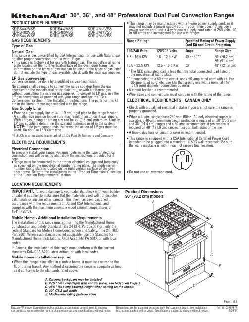
IMPORTANT:To avoid damage to your cabinets, check with your builder 194°F (90°C).codes.q Product Dimensions Page 1 of 2A.Optional backguard may be installedB.27¾" (70.5 cm) depth with control panel, see NOTE*C.35¾" (90.2 cm) cooktop height when setting on the wheelsD.36" (91.4 cm) widthE.Model/serial rating plate locationA.Optional backguard may be installedB.27¾" (70.5 cm) depth with control panel, see NOTE*C.35¾" (90.2 cm) cooktop height when setting on the wheelsD.48" (121.9 cm) widthE.Model/serial rating plate locationA.18" (45.7 cm) upper cabinet to countertopB.30" (76.2 cm) model: 30" (76.2 cm) min. upper cabinet width 36" (91.4 cm) model: 36" (91.4 cm) min. upper cabinet width 48" (121.9 cm) model: 48" (121.9 cm) min. upper cabinet widthC.13" (33 cm) max. upper cabinet depthD.For minimum clearance to top of range, see NOTE**E.30¼" (76.8 cm) on 30" (76.2 cm) models 36¼" (92.1 cm) on 36" (91.4 cm) models 48¼" (122.6 cm) on 48" (121.9 cm) modelsF.6" (15.2 cm) min. clearance from both sides of range to side wall or other combustible materialG.15" (38.1 cm)H.22" (55.9 cm) on 30" (76.2 cm) models 28" (71.1 cm) on 36" (91.4 cm) models 40" (101.6 cm) on 48" (121.9 cm) models I.1½" (3.8 cm)J.3" (7.6 cm)K.5" (12.7 cm)L.6" (15.2 cm) on 30" (76.2 cm) models 14" (35.5 cm) on 36" (91.4 cm) models 24" (61.0 cm) on 48" (121.9 cm) models M.10½" (26.7 cm)N.6" (15.2 cm)O.6" (15.2 cm), see NOTE***48" (121.9 cm) modelsNOTE:The following illustration is for dimension planning purposes only,and the locations and appearances of the features shown may not match *NOTE:When installed in a 24" (61.0 cm) base cabinet with 25" (63.5 cm)countertop; front of oven door protrudes 1⁷⁄₈" (4.8 cm) beyond 24" (61.0 cm) base cabinet.Cabinet DimensionsCabinet opening dimensions shown are for 25" (64 cm) countertop depth,24" (61 cm) base cabinet depth and 36" (91.4 cm) countertop height.Dimensions must be met in order to ensure a flush fit to backwall.IMPORTANT:If installing a range hood above the range, follow the range hood installation instructions for dimensional clearances above the cooktop *NOTE:Receptacle must be rotated 90°for Canadian installation.**NOTE: Minimum Clearances30" (76.2 cm) models: 30" (76.2 cm) minimum clearance between the top of the cooking platform and the bottom of an uncovered wood or metal cabinet.36" (91.4 cm) models: 42" (106.7 cm) minimum clearance between the top of the cooking platform and the bottom of an uncovered wood or metal cabinet.48" (121.9 cm) models: 42" (106.7 cm) minimum clearance between the top of the cooking platform and the bottom of an uncovered wood or metal cabinet.***NOTE:If backwall is constructed of a combustible material and abackguard is not installed, a 6" (15.2 cm) minimum clearance is required for all models.Page 2 of 2。
DM16LE内页说明书-A-02
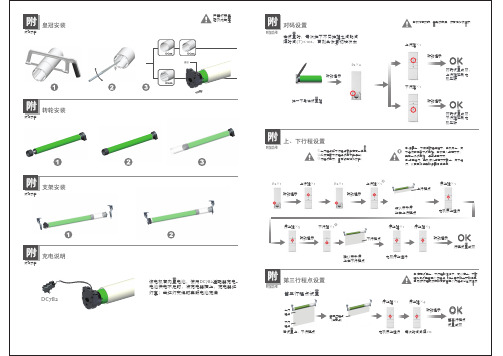
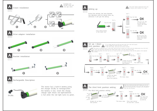
转轮安装附加功能附支架安装附加功能附充电说明附加功能附皇冠DC782该电机有内置电池,使用DC782适配器充电。
电池供电不足时,将充电器插上,充电器红灯亮;当红灯变绿时表明电池充满电机如已对码,重新对码后,原有记忆被清除;对码设置P2×2上行键下行键×1转动提示转动提示对码设置成功,上行键控制电机正转OK对码设置成功,下行键控制电机正转OK在设置时,每次按下不同按键之间的间隔时间(T)≤10s ,否则会恢复初始状态按一下马达设置键转动提示上、下行程设置附加功能附第三行程点设置附加功能附P2×1P2×1上行键×1停止键×5下行键×1上行键×1停止键转动提示转动提示转动提示停止键×5转动提示电机停止运行停止键×1电机停止运行确认帘子停止在上行程点确认帘子停止在下行程点行程设置成功OK① 调整上、下限位行程过程中,电机向上、向下运行时按一下设置键,电机进入步进方式,再按一次设置键,退出步进方式;② 步进运行:电机将以步进方式向上、向下运行,以便更加准确的调整限位位置;①上行程点和下行程点不能在同一位置;②必须完成下行程点设置才能退出;③行程设置好,具有断电记忆功能;上行程点下行程点① 在已设定上、下行程的情况下,可以在上、下行程之间设定第三个行程点,作为卷帘的半开的位置② 删除行程或对码的同时第三个行程点也会被清除第三行程点设置已设置上、下行程点下行程点上行程点第三行程点(任意点)停止键×1停止键×4每次时间间隔≥1s转动提示电机停止运行第三行程点设置成功OK。
Honeywell IH21 UHF RFID Reader 配件指南说明书
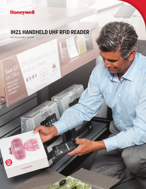
IH21 HANDHELD UHF RFID READER Accessories GuideACCESSORIESIH21-EPL-CT40IH21-EPL-CT50ePop-Loq Snap-On Adaptor for CT40Snaps easily on or off the mobile computer. Compatiblewith the homebase for terminal charging.ePop-Loq Snap-On Adaptor for CT60Snaps easily on or off the mobile computer. Compatiblewith the homebase for terminal charging.IH21 RFID READERSIH21A0002IH21A0014IH21 Bluetooth®RFID ReaderWith ePop-Loq®, UHFAntenna, Trigger Handle,Battery, Battery Cover, noimager, red and black. ETSIIH21 BluetoothRFID ReaderWith ePop-Loq, UHFAntenna, Trigger Handle,Battery, Battery Cover, noimager, red and black. FCCIH21-EPL-EDA50IH21-EPL-D75EePop-Loq Snap-On Adaptor for ScanPal™ EDA50Snaps easily on or off the mobile computer. Compatiblewith the homebase for terminal charging.ePop-Loq Snap-On Adaptor for D75eSnaps easily on or off the mobile computer. Compatiblewith the homebase for terminal charging.IH21 Handheld UHF RFID Reader Accessories Guide | 2ScanPal is a trademark or registered trademark of Honeywell International Inc. Bluetooth is a trademark or registered trademark of Bluetooth SG, Inc.ePop-Loq is a trademark or registered trademark of Technology Solutions (UK) Ltd.All other trademarks are the property of their respective owners.IH21 Handheld UHF RFID Reader Accessories Guide | Rev B | 06/19© 2019 Honeywell International Inc.For more informationHoneywell Safety and Productivity Solutions 9680 Old Bailes RoadFort Mill, SC 29707800-582-4263 IH21-CB-1IH21-QBC-1318-060-001IH21 Docking Homebase Kit includes power supply unit and mini USB lead. 4-Slot Battery Charger Must order 12V 4A power supply and power cord separately. Individual charge status LED for each battery slot in addition to a main power supply status LED.Spare Battery For IH21 RFID reader, 3.7V 2300 mAh.。
DT70说明书
DT70数字式重量变送器使用说明书天津市丽景微电子设备有限公司用前须知初次使用前,请详细阅读本说明书,现场使用许多疑难问题,在本说明书中将找到答案。
使用前,请检查称重系统其他部件是否匹配。
使用本仪表,注意防晒、防雨水、防撞击。
使用本仪表,请尽可能配备常用安装、检修工具:小型一字螺丝刀,数字式万用表,称重传感器模拟器(mV信号发生器)。
本产品安按照国标GB/T 7724-1999要求,进行严格品质保证,符合各项标准本产品已通过CE认证※ 注:使用四线制传感器时,需把EX+和SEN+短接,EX-和SEN-短接。
※ 注:如需要DT70通讯部分说明书,请另外跟厂商索取。
注:本公司保留对产品进行修改和改进的权力,因此,技术上的改进,恕不另行通知。
目录概述1–1 简介 (1)技术参数2–1 DT70仪表订货代码 (2)2–2 DT70选配件订货代码 (3)2–3 一般参数 (4)2–4 数字部分 (4)2–5 模拟部分 (4)安装与接线说明3–1 安装注意事项 (5)3–2 安装尺寸图 (5)3–3 接线图及接线端子列表 (7)3–4 显示面板 (10)基本操作图4–1 DT70功能框架图 (13)4–2 操作流程 (13)4–3 DT70功能树图 (14)一般功能设置5–1 功能设定步骤 (19)5–2 功能设定列表 (20)通讯参数设定及通讯协议6–1 通讯参数设定 (23)6–2 通讯参数列表 (24)仪表标定7–1 标定操作步骤 (27)7–1–1 实物标定 (27)7–1–2 数字标定 (28)7–1–3 标定系数 (29)7–1–4 模拟量输出 (30)7–2 标定参数列表 (31)7–2–1 实物标定参数列表 (31)7–2–2 数字标定参数列表 (31)7–3 设备可能显示的错误代码 (32)诊断功能8–1 诊断功能操作步骤 (34)8–2 诊断功能列表 (34)8–3 诊断功能具体描述 (34)8–3–1 毫伏值显示 (34)8–3–2 按键测试 (35)8–3–3 显示测试 (35)8–3–4 显示版本号 (35)8–3–5 显示序列号 (35)8–3–6 外部控制输入测试 (35)8–3–7 继电器输出测试 (35)8–3–8 参数恢复出厂设定 (35)8–3–9 通讯口测试 (36)8–3–10 模拟量输出测试 (36)8–3–11 IAP升级 (36)称重定值比较量设置9–1 设置参数步骤 (37)9–2 高低限参数设置列表 (38)输入/输出10–1 开关量输入 (39)10–1–1 输入接口与外接开关的联接 (39)10–1–2 输入接口与PLC的联接 (40)10–2 开关量输出 (41)10–2–1 输出接法 (41)10–2–2 输出说明 (41)10–2–3 比较条件说明 (41)10–3 模拟量输出 (42)10–3–1 技术规格 (42)11 记录1 概述1–1 简介DT70应变传感器数字变送控制器(以下简称变送器)是一种多用途重量信号转换设备,集显示、变送和控制于一体,具有串行数字信号输出,模拟信号输出等多种功能;采用导轨安装方式,体积小、重量轻;DT70经过严格的电磁兼容性测试,性能可靠。
高兰地铁路公司产品说明书

sand
d u nes and
h ard
sand y
b each .
Th e D ee sid e L i nc ,
w h ich g rand
ru
est
mnsouanlotnagi n
th e p i ctu resq ue sce ne ry i n th e K
v al ley of
i ng d om.
B RA E M A R via B almo ral .
G lf O
. —The re are e xce lle nt G olf C o urses at many p lace s o n th e Railw ay.
A full li st may b e ob tai ned o n ap pli cation . T h e C o m p any’s G o lf C o u r se at C r u d e n
th e D e e , te rm i nate s at Ballate r amo ng th e
B A L M ORA L ,
th e
K ing ’ s Hi g h land
home, is
w ith in
ni ne miles of
B
al
lat
e
r .
C oach es run d ai ly d uri ng summe r b etw e e n B allate r and
w ho w i sh to b reak thei r o urn ey b efore proce eding to k ye .
I t i s an ideal spot for Vi sitors i n search of qui et.
COT-UN5200A 产品说明书
COT-UN5200A产品说明书文档版本:V20190215 目录1 功能特点 (3)2 快速入门 (4)2.1 硬件连接 (4)2.2 网络环境 (4)2.3 设备默认参数 (6)2.4 传输测试 (7)3 产品概述 (8)3.1 技术指标 (8)3.2 外形尺寸(毫米) (9)3.3 接口定义 (10)3.4 S1跳线功能 (11)4 网络基础功能介绍 (12)4.1 IP地址/子网掩码/网关 (12)4.2 网页配置 (13)4.3 指示灯状态 (14)4.4 网络工作模式 (14)4.4.1工作模式:TCP Server (15)4.4.2工作模式:TCP Client (15)4.4.3工作模式:UDP Client (16)4.4.4工作模式:UDP Server (17)4.5 串口功能 (17)4.6特色功能 (18)4.6.1 心跳包功能 (18)4.6.2 Modbus网关功能 (18)4.6.3 注册包功能 (18)4.6.4 数据路由功能 (19)5 AT指令配置 (21)1 功能特点n采用高速高性能ARM处理器,工业级工作温度,硬件TCP/IP协议栈稳定可靠n DC9-32V宽工作电压,多重保护,正反接自适应n10/100Mbps自适应网络,支持TCP Server、TCP Client、UDP Server、UDP Client 多种工作模式n内置中英文网页,可通过WEB网页进行参数配置n支持RS232和RS485端口,两个端口可以同时独立工作,互不影响n支持RTS/CTS硬件流控功能n串口波特率支持1200bps~115.2Kbps;支持None、Odd、Even校验方式n支持Modbus网关功能,工业现场使用方便n RJ45带Link/Data指示灯,网口内置隔离变压器,1.5KV电磁隔离n允许用户自定义MAC地址n支持静态IP地址和DHCP自动获取IP地址n支持keepalive机制,可快速探查死连接等异常并快速重连n支持修改密码,可用于网页参数修改,更安全n支持路由功能,可选择网络数据、串口数据的传输方向[ 产品图示]2 快速入门COT-UN5200A模块用于实现串口到以太网口的数据的双向透明传输,用户无需关心具体细节,模块内部完成协议转换。
蜂巢智能 Holywell CN75 和 CN75e 手持计算机用户指南说明书

The CN75 and CN75e mobile computers’ no-compromise design provides the power and performance required by today’s mobile fieldservice and transportation workers.CN75Ultra-Rugged Mobile ComputerThe Honeywell CN75 and CN75e mobile computers offer the versatility customers demand, providing the choice of aWindows® or Android™ operating system on a single device to meet changing enterprise business demands.The no-compromise design is powered by a 1.5 GHz dual-core, multi-engine processor with 2 GB RAM and 16 GB Flash, offering the highest degree of future-proofing capability.Specifically designed for mobile field service workers who need power and performance in a compact form factor, the Honeywell CN75 mobile computer offers the perfect balance of ruggedness, duty cycle and ergonomics while providing unparalleled versatility. The CN75e device offers the same power-packed computing but with a larger keypaddesign, making it ideal for delivery environments where workers may be wearing gloves or have more data input–intensive applications.The CN75 and CN75e mobile computers deliver unparalleled reliability with smart battery technology that provides enough power to last a full work shift, eliminating dead batteries and downtime. The CN75 and CN75e mobile computers are also equipped with a high-performance imager that provides fast and accurate barcode scanning capabilities even in low-light scanning environments, with unmatched motion tolerance to eliminate costly delays in scan-intensive applications.The no-compromise design extends to radio connectivity, as well. The wide-area solutions feature a Flexible Network voice and data WWAN radio that operates on networks worldwide, offering switch-on-the-fly network selection capability and eliminating the need for multiple pools of devices dedicated to one network.FEATURES AND BENEFITSSupports Windows Embedded Handheld 6.5 and Android 6.0 Marshmallowoperating systems for flexible application support and migration.Flexible radiotechnology provides optimal network coverage and asuperior solution for implementing least- cost routing strategies.Withstands 2.4 m (8 ft) drops to concrete, 2,000 (1 m) tumbles and has an IP67 seal rating against rain and dust.Advanced barcode imaging technology with motion tolerance for snappy scanning and white illumination with laser aiming for high read rates.Full compatibility with printers,application software, communications and a complete set of peripherals andaccessories, enabling a comprehensive enterprise business solution.PHYSICAL CHARACTERISTICSCN75 Dimensions with Battery:L x W x D: 16.9 cm x 8.0 cm x 3.4 cm (6.65 in x 3.15 in x 1.34 in)Weight: 450 g (15.9 oz) with batteryCN75e Dimensions with Battery:L x W x D: 19.5 cm x 8.0 cm x 3.4 cm (7.66 in x 3.15 in x 1.34 in)Weight: 491 g (17.3 oz) with batteryENVIRONMENTALOperating Temperature: -20°C to +60°C (-4°F to +140°F)*Storage Temperature: -30°C to +70°C (-22°F to +158°F)Charging Temperature: +5°C to +35°C (41°F to 95°F)Relative Humidity: Non-condensing, 95%Rain and Dust Resistance: IP67Drop Spec: 2.4 m (8 ft) to concrete per MIL-STD 810G, 1.8 m (6 ft) to concrete across operating temperature range per MIL-STD 810G, 2,000 (1 m) tumbles per IEC 60068-2-32 specification Electrostatic Discharge: +/-15 kV air discharge; +/-8 kV direct dischargePOWERBattery Pack: 3.7 V, 4000 mAh; IEEE 1725 compliant, Li-Ion, removable, rechargeableOPERATING SYSTEM:Microsoft® Windows Embedded Handheld 6.5 or Android 6.0 Marshmallow with GMSMULTI-ENGINE PROCESSOR ARCHITECTURETexas Instruments 1.5 GHz OMAP 4470 dual-core, multi-engine processor architectureMEMORYRAM: 2 GBROM: 16 GB FlashStorage Expansion: Customer-accessible micro-SD slot for removable memory cards up to 32 GBDISPLAY8.9 cm (3.5 in) Transmissive VGA480 x 640 pixels65,536 (16-bit RGB) colorsHigh-durability touch screenHardened Corning® Gorilla® Glass display for superior durabilityLED backlightAmbient light sensorSTANDARD COMMUNICATIONSUSB – Full Speed 2.0 Host, USB – Full Speed 2.0 Client SOFTWARE APPLICATIONS ANDCOMPONENTSDevice Management:SmartSystems™ Foundation providesa single, integrated environmentfor hands-free deployment andmanagement of devices on-siteor remote. Also compatible withleading third-party data and devicemanagement products.ScanNGo for easy barcode-basedenterprise-wide device provisioning.It can be used to download devicemanagement software from HoneywellISVs.CloneNGo, a peer-to-peer devicemanagement software that enablessimple device cloning, eliminating theneed to use a management console fordevice provisioning.Application Development: HoneywellDeveloper LibraryDevice Health Monitoring: On-boardmonitoring of key subsystems includingscanning, communications and batterylifeOptional Honeywell Enterprise ClientPack: Terminal Emulation and HTML 5BrowserOptional Launcher: Application lockingDATA MANAGEMENTSkynax® Mobile CommunicationsINTEGRATED RADIOSWireless WAN: Worldwide Voice and Data(can switch between UMTS and CDMAradio networks)UMTS/HSPA+UMTS Frequencies: 800, 850,900, 1900, 2100 MHzGSM/GPRS/EDGE Frequencies:850, 900, 1800, 1900 MHzMax Speeds (Networkdependent): Uplink – 5.76Mbps; Downlink – 14.4 MbpsCDMA/EV-DO Rev ADual Band CDMA2000 Bands:BC0 & BC1 (800/1900 MHz)Max Speeds (NetworkDependent): Uplink – 1.8Mbps; Downlink – 3.1 MbpsWireless LAN: IEEE 802.11 a/b/g/nSecurity: Wi-Fi Certifiedfor WPA and WPA2,Authentication: 802.1xCisco Compatibility: CCXv4Encryption: WEP (64- or128-bit), AES, TKIPWireless PAN: Integrated Bluetooth®Power Class 1.5 Version 4GLOBAL POSITIONING SYSTEM(with WAN Radio Option): 12-channelintegrated GPS; network-independentautonomous mode; supports assistedoperation via XTRA®, CP E911GPS dedicated AT commandsProtocol: NMEA-0183 V2.3Tracking Sensitivity: better than -158dBmGLONASS supportSENSOR TECHNOLOGYAccelerometer: Embedded accelerometerenables automatic or application-specificfeatures such as screen rotation or systemsuspendAUDIO SUPPORTSupports VoIP/speech recognition/push-to-talk applications; front andrear speakers; rear speaker >80 dB at40 cm (15.7 in); front receiver and frontpanel microphone for handset audioommunication and audio recording;ireless Bluetooth headset support; wiredheadset support via snap-on adapterINTEGRATED SCANNEREA30 High-Performance Motion-Tolerant 2D Imager: (up to 500 in/s)white LED illumination; red laser aimerand framer optimized for all lightingconditions. Capable of scanning allcommon 1D and 2D barcodes; 1D assmall as 4 mils; 2D as small as 6.6 mils.Refer to User’s Manual for depth-of-fieldperformance.INTEGRATED CAMERA5-megapixel auto-focus color camerawith LED flashKEYPAD OPTIONSAll keypad options feature backlit hardkeycaps with laser-etched legends.CN75:NUMERIC KEYPAD QWERTY KEYPADCN75e:LARGE NUMERIC KEYPAD LARGE QWERTY KEYPADCN75/CN75e Mobile Computer Datasheet | Rev B | 08/21© 2021 Honeywell International Inc.For more informationHoneywell Safety andProductivity Solutions300 S Tryon St Suite 500Charlotte, NC 28202877-841-2840For a complete listing of all compliance approvals and certifications, please visit /compliance . For a complete listing of all supported barcode symbologies, please visit/symbologies .Microsoft, Windows, and the Windows Logo are registered trademarks or trademarks of Microsoft Corporation. ScanPal is a trademark or registeredtrademark of Honeywell International Inc.Android is a trademark or registered trademark of Google LLC.Bluetooth is a trademark or registered trademark of Bluetooth SG, Inc.Corning and Gorilla Glass are trademarks or registered trademarks of Corning, Inc.Qualcomm is a trademark or registered trademark of Qualcomm Incorporated.All other trademarks are the property of their respective owners.HONEYWELL GLOBAL SERVICES SUPPORTContact for Support: Public Knowledgebase Articles:Telephone support available in North America (800-782-4263). Outside of this area, contact your local representative.ACCESSORIESFlexDock modular docking system, vehicle dock, vehicle holder, snap-on adaptors, removable scan handle, magnetic stripe reader, 6822 full-page printer and PW50 workboard printerREGULATORY APPROVALS AND COMPLIANCECN75LAN, CN75WANSafety: cULus Listed, BSMIEMC: Class B – FCC/ICES/EN, GOST-R Radio: FCC, Industry Canada, A-tick (AU), NCC, IDA,ICASA, POSTEL, NTC, ETA, SIRIM, ANATELEnvironmental: EU Directives-WEEE; RoHS; Batteries and Accumulators; Packaging and Waste Packaging NON-INCENDIVE VERSIONCN75 and CN75e with NI certification comply with the following: Suitable for use in Division 2 locationsSafety: cULus Listing – ISA/ANSI 12.12.01Gases: Class I – Groups A, B, C, D Dusts: Class II – Groups F, G Fibers and Flyings: Class III*Max. Ambient:50°C (122°F) T6。
埃尔克斯电子产品的五种型号功能规范说明书

SPECIFICATIONS13Models 7520DT, 7530DT, 7540DT, 7550DT and 7564SAFunctional SpecificationsINPUTVoltage 115/230 VAC 15, Single Phase, User selection Frequency 50/60 Hz 5Fuse6.3 Amp 250V Slo-Blo for 7550DT and 7564SA 5 Amp 250V Slo-Blo for 75/20/30/40DTDIELECTRIC WITHSTAND TEST MODEOutput Rating5 KV @ 40 mA for 7550DT and 7564SA, 5 KV @ 20mA for 75/20/30/40DT6 KV @ 10 mA DC for 75/30/40/50DT and 7564SAOutput AdjustmentRange:0 - 5 KV AC 0 - 6 KV DCResolution: 1 volt/step Accuracy:(2 of setting 5 volts) Ramp-HI 12mA peak maximum, ON/OFF selectableCharge-LORange:0.0 - 350.0A DC or Auto setHI-Limit AC Range:0.00 - 40.00 mA for 7550DT and 7564SA, 0.00 - 20.00 mA for 75/20/30/40DT Resolution: 0.01 mA/step Accuracy: (2 of setting 2 counts) DC Range:0 - 9999AResolution: 1A/stepAccuracy:(2 of setting 2 counts) LO-Limit AC Range:0.000 - 9.999 mA Resolution: 0.001 mA/stepAccuracy: (2 of setting 2 counts) DC Range:0.0 - 999.9 AResolution: 0.1A/stepAccuracy:(2 of setting 2 counts) Arc Detection Range:1 - 9Failure DetectorAudible and VisualRecycledEquipment(410)email:***************************1981SPECIFICATIONS14Voltage Display Range: 0.00 - 6.00 KV Full Scale0.00 - 5.00 KV Full Scale for 7520DT onlyResolution: 10 volt/stepAccuracy: (2 of reading 2 counts)Current Display Auto RangeAC Range 1: 0.000mA - 3.500mAResolution: 0.001mA/stepRange 2: 3.00 - 40.00 mA for 7550DT and 7564SA,3.00 - 20.00 mA for 75/20/30/40DTResolution: 0.01 mA/stepDC Range 1: 0.0 A - 350.0 AResolution: 0.1A/stepRange 2: 300 A - 3500 AResolution: 1A/stepRange 3: 3000 A - 9990 AResolution: 10A/stepAccuracy: All Ranges (2 of reading 2 counts)DC Output Ripple 4**********************,ResistiveLoad Discharge Time 200 msMaximum CapacitiveLoad DC Mode1uF < 1KV0.75uF < 2KV0.5uF < 3KV0.08uF < 4KV0.04uF < 5KV0.01uF < 6KVAC Output Wave Form Sine Wave, Crest Factor = 1.3 - 1.5Output Frequency Range: 60 or 50 Hz, User SelectionAccuracy: 1%Output Regulation (1 of setting 5 volts) from no load to full load Dwell Timer Range: 0, 0.3 - 999.9 sec (0 = Constant)Resolution: 0.1 sec incrementsAccuracy: (0.1% + 0.05 sec)Ramp Timer Range: AC 0.1 - 999.9 secDC 0.4 - 999.9 secResolution: 0.1 sec incrementsAccuracy: (0.1% + 0.05 sec)RecycledEquipment(410)email:***************************SPECIFICATIONS15Ground Continuity For 75/20/30/40/50DT Current : DC 0.1 A 0.01A, fixedMax. ground resistance : 1 0.1, fixed Ground Fault Interrupt GFI Trip Current: HV Shut Down Speed: 450 A max (AC or DC)< 1msINSULATION RESISTANCE TEST MODE Model 75/30/40/50DT, 7564SAOutput VoltageRange:100 - 1000 Volts DC Resolution: 1 volt/step Accuracy:(2 of reading 2 volts) Short Circuit Current Maximum: 12mA peak Voltage DisplayRange: 0 - 1000 VResolution: 1 volt/stepAccuracy:(2 of reading 2 counts) Resistance DisplayRange: 1 - 9999 M (4 Digit, Auto Ranging)Resolution:500VDC 1000VDC M M M 0.001 1.000 - 5.388 1.000 - 9.999 0.01 1.40 - 53.88 2.80 - 99.99 0.1 14.0 - 538.8 28.0 - 999.9 1104 - 9999280 - 9999Accuracy:(2 of reading 2 counts) at test voltage 500 - 1000V and 1 - 1000 M(8 of reading 2 counts) at test voltage 500 - 1000V and 1000 - 9999 M(8 of reading 2 counts) at test voltage 100 - 500V and 0 - 1000 MCharge-LO Range: 0.000 - 3.500A or Auto Set HI-Limit Range: 0 - 9999 M (0 = Off) LO-Limit Range: 1 - 9999 MDelay TimerRange: 0, 0.5 - 999.9 sec (0 = Constant) Resolution: 0.1 sec/stepAccuracy:(0.1% + 0.05 sec)Ground Fault InterruptGFI Trip Current:HV Shut Down Speed:450 A max (AC or DC) < 1msRecycledEquipment(410)email:***************************SPECIFICATIONS16GROUND BOND TEST MODE Model 7564SA onlyOutput Voltage Range: 3.00 - 8.00 Volts AC (Open Circuit Limit) Resolution: 0.01 volt/stepAccuracy: (2 % of Setting + 0.03V ) O.C. Condition Output Frequency Range: 60 or 50 Hz, User Selection Accuracy: 1%Output CurrentRange: 3.00 - 30.00 Amps AC Resolution: 0.01 Amp/stepAccuracy :(2 % of Setting + 0.02 A) Current DisplayRange: 0.00 - 30.00 Amps Resolution: 0.01 Amp/stepAccuracy:(3 % of Reading + 0.03 A) Resistance DisplayRange: 0 - 600 m Resolution: 1 m /stepAccuracy:(2 % of Reading + 2 m ) HI-LimitRange: 0 - 600 m for 3 - 10 A 0 - 150 m for 3 - 30 A Resolution: 1 m /stepAccuracy:(2 % of Setting + 2 m ) LO-LimitRange: 0 - 600 m for 3 - 10 A 0 - 150 m for 3 - 30 A Resolution: 1 m /stepAccuracy:(2 % of Setting + 2 m ) Dwell TimerRange: 0, 0.5 - 999.9 sec (0 = Constant) Resolution: 0.1 sec/step Accuracy:(0.1% + 0.05 sec)Milliohm OffsetMax. Offset Capability: 200 mResolution: 1 m / stepAccuracy:(2 % of Setting + 2 m )RecycledEquipment(410)email:***************************SPECIFICATIONS17GENERAL SPECIFICATIONSPLC Remote Control Input - Test, Reset, Recall memory 1, 2 and 3Output - Pass, Fail, Test-in-ProcessMemory Allows storage of up to 50 groups different test programsand 8 step/each memory. Step is not available on 7520DT SecurityProgrammable password lockout capability to avoid unauthorized access to test set-up program. LCD Contrast Setting 9 ranges set by the numeric keys on the front panel. Buzzer Volume Setting 10 ranges set by the numeric key on the front panel.Calibration Software and adjustments are made through front panel. Mechanical Bench or rack mount with tilt up front feet. Dimension7540DT, 7550DT and 7564SA:(W x H x D) 17 x 5.8 x 20.3 in. (432 x 147 x 515 mm) 7520DT and 7530DT:(W x H x D) 17 x 5.8 x 12 in. (432 x 147 x 305 mm)Weight7564SA without scanner 52.5 lbs (24 Kgs) 7564SA with built-in scanner 57.0 lbs (26 Kgs) 7550DT without scanner 50.5 lbs (23 Kgs) 7550DT with built-in scanner 55.0 lbs(25 Kgs) 7540DT with 4 port scanner 39.6 lbs (18 Kgs) 7540DT with 8 port scanner41.8 lbs(19 Kgs) 7530DT scanner not available 24.8 lbs (11.27 Kgs) 7520DT scanner not available 24.8 lbs(11.27 Kgs)Scanner Port Two Port Maximum including the built-in scanner. Not available on 7520DT, 7530DT and 7540DT.Scanner Built-in OptionHigh Voltage x 4 Ports (7540DT only)High Voltage x 8 Ports (75/40/50DT and 7564SA) Ground Bond x 8 Ports (7564SA only)RecycledEquipment(410)email:***************************。
eDM16LE内页说明书-A-02
CrownAAdditionalf u n c t i o nDrive adapter installationAAdditionalf u n c t i o nBracket installationA Additional f u n c t i o n Rechargeable DescriptionIf the motor already experienced match code,the memory will be cleared if do it againP2×2Up×1Down×1Set up is ok. Theup limit buttoncontrol the motorclockwise.OKSet up is ok. Thedown limit buttoncontrol the motorclockwise.OKPress setting buttonof the motor onceSetting upDuring the settings, the time betweentwo operation must be shorter than 10s,otherwise it will quit the settingRun for hintRun for hintRun for hintRun for hint① In the process of adjusting the up / down limit: when the motor moving up or down, press the setting button once, the motorwill be under the step-moving status,press the setting button again to quit the step-moving status② The step-moving status: the motor will run up or down by the way of step-moving so that the limit position can be adjustedmore correctlyP2×1P2×1Up×1Up×1Stop×1Stop×1AAdditionalf u n c t i o nSet up / downlimit positionRun for hint Run for hint OK① It is invalid when the up limit and down limit are at the same location② Must complete the down limit point to limit set;③ After limit setting with power and memory function;Stop×5Stop×5Confirm the Blindto stop in thedown limit positionThe uplimit pointThe downlimit pointThe motor stopsThe motor stopsSetting is okConfirm the Blindto stop in the uplimit positionDown×1Run for hintOKStop×1Run for hintThe motor stops① After the up limit and down limit setting, you can setthe third limit point between them as the half open position② The third limit point will be cancelled as the cancellationof limit and code matchingThe third limit position settingAAdditionalf u n c t i o nThe third limit position settingAlready set up, downlimit positionThe uplimitpositionThe downlimitpositionThe thirdlimit position(any position)Stop×4The third limitpoint settingsuccessfullyEvery time intervalnot less than 1 secondDC782The motor has a built-in battery,using the charger DC782 to recharge.when the battery is low, insert the charge, charger light shows red light.batteriesis full when the red light turns to green.。
FL45200A系列高容量直读流量计说明书
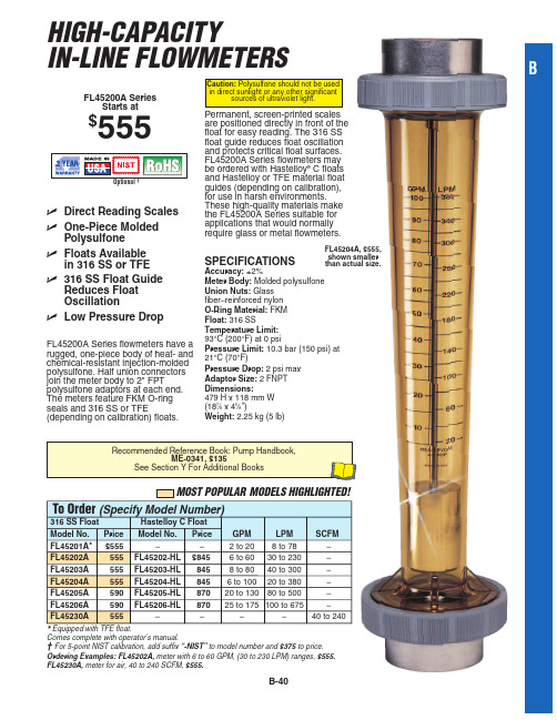
FL45200A Series flowmeters have a rugged, one-piece body of heat- and chemical-resistant injection-molded polysulfone. Half union connectors join the meter body to 2" FPT polysulfone adaptors at each end. The meters feature FKM O-ring seals and 316 SS or TFE (depending on calibration) floats.
S+ DQG &RQGXFWLYLW\
Conductivity Instrumentation, Dissolved Oxygen Instrumentation, Environmental Instrumentation, pH Electrodes and Instruments, Water and Soil Analysis Instrumentation
To Order (Specify Model Number)
316 SS Float
Hastelloy C Float
Model No. Price Model No. Price GPM
LPM
SCFM
FL45201A* $555
–
–
2 to 20 8 to 78
–
FL45202A
555 FL45202-HL $845 6 to 60 30 to 230
拓普测量ES-50系列全站仪使用手册说明书

内含锂离子电池 锂离子电池报废时必须回收或者正确处理。
:这是日本测量仪器制造厂商协会的标志。
ii
如何阅读本说明书
符号约定
本说明书使用下列符号和约定:
[观测]等 {ESC}等 <放样>等
:表示操作前应阅读的注意事项和重要内容。 :表示参见的章节及其名称。 :表示补充说明。 :表示某个特别术语或操作的说明。 :表示所显示的软键内容。 :表示 ES 操作键盘上的操作键。 :表示显示界面名称。
关于本说明书的约定
· 除特殊说明外,本说明书中的“ES”表示ES-52/55。 · 本说明书中所用显示界面均来自ES-52仪器。 · 说明书界面中所采用的软键功能菜单均为出厂时的默认值,软键功能菜单可由用户
自行改变。
什么是软键:“4.1仪器部件名称”和软键自定义“30.3键功能定义”
· 在阅读各测量操作章节之前,请先阅读“5.基本操作”的内容,了解仪器的基本操 作方法。
· 有关参数设置项的选取和数据输入方法,参见“5.1键盘基本操作”。
· 说明书中介绍的测量程序均采用“连续测量”模式。选取其它测量模式时的操作程
序信息将随
给出。
·
表示该功能/选项并非所有的产品都具有。关于您的产品是否具有,请联系您当
地的代理商。
· KODAK为柯达公司注册商标。
· 本说明书中出现的其它公司或产品名称均为相应公司商标或注册商标。
轻松测量普及型全站仪 使用手册
ES-50 系列
ES-52 ES-55
测量仪器
ES-50 系列
3R 级激光产品
使用手册
· 感谢您选购ES-52/55全站仪。在本说明书中,除特殊说明外,ES即指ES-52/55全站 仪。
深煎油测试仪 油质表 DT-70 用户手册说明书
User ManualDeep Frying Oil Tester / Oil Quality Meter DT-70Contents1Safety notes (1)2Technical specifications (2)3Interpretation of the measured values (2)4Device description (3)5Measurement (4)6Settings / configuration mode (4)7Advanced alarm settings (5)8Calibration (5)9Warranty (6)10Disposal (6)1 Safety notesPlease read this manual carefully and completely before you use the device for the first time. The device may only be used by qualified personnel and repaired by CE M Instruments personnel. Damage or injuries caused by non-observance of the manual are excluded from our liability and not covered by our warranty.•The device must only be used as described in this instruction manual. If used otherwise, this can cause dangerous situations for the user and damage to the meter.•The instrument may only be used if the environmental conditions (temperature, relative humidity, …) are within the ranges sta ted in the technical specifications. Do not exposethe device to extreme temperatures, direct sunlight, extreme humidity or moisture. Thedevice is intended for indoor use.•Before the measurement, the device should have stabilised at ambient temperature, which is important when moving from cold to warm rooms and vice versa.•Do not expose the device to shocks or strong vibrations.•The case should only be opened by qualified CE M Instruments personnel.•Before making a measurement, make sure the device is entirely closed.•Never use the instrument when your hands are wet.•You must not make any technical changes to the device.•The appliance should be cleaned with a damp cloth after each use. Use only pH-neutral cleaner, no abrasives or solvents.•The device must only be used with accessories from CE M Instruments or equivalent.•When the frying oil tester is not used for a longer period of time, remove the batteries.•Do not store the meter together with any chemicals.•Before each use, inspect the case for visible damage. If any damage is visible, do not use the device.•Wear your personal protective equipment during each measurement to avoid injury.This also applies to other people near the measuring location as oil splashes can causeserious injury to human skin and eyes.•To avoid burns, never touch the sensor or the metal shaft directly after the measurement as these parts can become very hot when they are immersed into hotoil.•Remove the oil quality meter from the oil when you leave the place.•Do not use the instrument in explosive atmospheres. Also avoid proximity to explosive, easily flammable or chemical substances when the sensor is hot.•Only use the device in systems that are electrically tested on a regular basis. Never connect the conductive metal parts of the meter with a source of voltage. Inspect thesystem visually before each measurement. If there are any signs of damage, do notcarry out any measurements until the problem has been resolved.•The measurement range as stated in the specifications must not be exceeded under any circumstances.•Non-observance of the safety notes can cause damage to the device and injuries to the user.We do not assume liability for printing errors or any other mistakes in this manual.We expressly point to our general guarantee terms which can be found in our general terms of business.If you have any questions please contact CE M Instruments. The contact details can be foundat the end of this manual.a certain percentage, depending on the type of oil/fat.4 Device description5 Measurement1.Press and release the on / off key to switch on the device.2.The temperature display will show “Lo”.3.The PC display will show “- - -“.4.Insert the sensor into the hot oil so that the oil level is between the minimum and maximum lines on the metal shaft.5.If you want to freeze the measured value in the display, press the HOLD key.6.Press the HOLD again to deactivate the HOLD function.7.When the temperature indication flashes and shows "HI", the oil/fat is too hot and exceeds the upper end of the measurement range of 200 °C.8. When the temperature indication flashes and shows "Lo", the oil/fat is too cold and is below the lower end of the measurement range of 30 °C.9. When the PC indication flashes and shows "Lo," the oil/fat used is not suitable to be tested with the DT-70.Important notes to achieve the most accurate results-During the measurement, there should not be any fried food in the oil/fat. After taking out the fried items, wait at least 5 minutes before making a measurement.-If you would like to measure in an induction cooker, switch it off as its electromagnetic field can falsify the result.-Stir the oil/fat briefly with the device to ensure an even temperature.-Avoid direct contact with metal objects such as cooking pots or frying baskets as this can influence the measurement result. Minimum distance: 1 cm.-Replace the oil/fat when a PC value of 24 % is reached. Different countries have different threshold values to stick to. It is recommended to replace the oil/grease before reaching the threshold value.6 Settings / configuration modeActivate the configuration mode by pressing the HOLD key and the arrow left key at the same time. Now you can navigate through the submenus, make the desired settings and confirm these by pressing the HOLD key. The next menu will open automatically.Set temperature unitSwitch on the device and press the HOLD key and the arrow left key simultaneously for approx.3 seconds. °C or °F will appear in the display.e the arrow keys to set the temperature unit (°C/°F).2.Confirm the selected temperature unit by pressing the HOLD key to confirm.Switch on / off audible alarm (ALA)e the arrow keys to switch on / off the audible alarm (ALA).4.Press the HOLD key to confirm.Switch on / off Auto Power Off function (OFF)5.Press the arrow keys to switch on / off the Auto Power Off function.6.Confirm your selection with the HOLD key.Switch on / off alarm LEDe the arrow keys to turn on / off the LEDs.8.Press the HOLD key to confirm.Switch on / off calibration mode (CAL)9.Press the arrow keys to switch on / off calibration mode.10.Press the HOLD key to confirm.Reset device to factory settings (RST)e the arrow keys to reset the device to its factory settings (on).12.Press the HOLD key to save and exit.Switch the background lighting (BL) on or off13.Press the arrow keys to turn on / off the backlight.14.Press the HOLD key to save and exit.To leave configuration mode, press the on / off key.7 Advanced alarm settingsSwitch on PC alarm (High)1.Switch on the device and hold down the arrow left key for approx. 3 seconds until the LEDsturn red.e the arrow keys to set the alarm value.3.Save the setting by pressing the HOLD key or press the on / off key to return to measurementmode without saving.Switch on PC alarm (Low)1.Switch on the device and hold down the arrow right key for approx. 3 seconds until the LEDsturn green.e the arrow keys to set the alarm value.3.Save the setting by pressing the HOLD key or press the on / off key to return to measurementmode without saving.8 Calibratione a reference oil with a known PC value for calibration. Heat the oil to 50 °C.2.Enter calibration mode as described above. “CAL” will be displayed. Immerse the sensor intothe calibration oil. Make sure the oil is between the Min/Max lines on the sensor shaft.3.When the reading has stabilised, press the arrow keys to adjust the reading in increments of0.5 %.4. When the displayed value matches the reference value, press the HOLD key to save the value. You can reset your calibration to factory settings by opening the menu item factory settings (RST) via the configuration mode as described under Settings and then pressing the arrow right key and the HOLD key.9 WarrantyYou can read our warranty terms in our General Business Terms and Conditions which you can find here: https://testmeter.sg/page/terms.10 DisposalFor the disposal of batteries in the EU, the 2006/66/EC directive of the European Parliament applies. Due to the contained pollutants, batteries must not be disposed of as household waste. They must be given to collection points designed for that purpose.In order to comply with the EU directive 2012/19/EU we take our devices back. We either re-use them or give them to a recycling company which disposes of the devices in line with law.For countries outside the EU, batteries and devices should be disposed of in accordance with your local waste regulations.If you have any questions, please contact CE M Instruments.CE M Instruments contact informationChinaCEM Instruments19th Building, 5th Region, Baiwangxin Industry Park, Songbai Road, Baimang, Xili, Shenzhen,China P.C. 518108Tel.: +86 (755) 27353188Fax: +86 (755) 27652253 / 27653699 cemyjm@ce www.ce SingaporeGMM Technoworld Pte Ltd 8, Burn Road, #05-01 Trivex Singapore 369977T ele phone: +656386 1815 WhatsApp: +658218 9655 sales@testmeter.sg www.testmeter.sg。
SEIKO C-7使用说明书
7B24使用说明书应对世界3个地区的太阳能电波 日本、中国、美国※ 选购时的金属表带,可在经销店或本公司售后服务中心进行调整。
在其他商店进行调整可能会收费,或不能得到服务。
承蒙选购本公司的产品,谨在此表示衷心的感谢。
使用之前,请熟读本说明书,并正确地使用手表。
本说明书请安放在随手能看到的地方,以便必要时参阅。
BSC7B24-A 210923123456781. 使用产品时的注意事项..............................................4 特点......................................................................................6 各部件的名称和主要功能.........................................8 关于B 按钮 ....................................................................10 关于表把..........................................................................112. 使用之前..........................................................................12 确认能源余量...........................................................12 确认时间和日期......................................................133. 接收电波,以对准时间和日期。
........................14 接收电波的机制......................................................14 自动接收和强制接收.. (15) 接收环境.....................................................................16 大致的接收范围:日本(JJY) .......................16 大致的接收范围:中国(BPC) ......................17 大致的接收范围:美国(WWVB) .................18 为了容易接收电波.................................................19 接收困难的环境......................................................20 确认是否能够接收......................................................22 接收结果的显示......................................................224. 什么是时差修改功能是什么..................................24 时差修改功能的特点............................................24 关于时差修改功能的问答..................................25 设定时差(选择接收局) .........................................26 世界主要地区时差一览表 (28)5. 关于充电充电................................................................30 充电的方法................................................................30 充电大致所需时间.................................................31 关于能源..........................................................................32 能源短缺预告功能.................................................32 节能功能.....................................................................336. 注意事项..........................................................................34 维修...............................................................................34 性能与型号................................................................35 防水性能.....................................................................36 抗磁性能(磁性的影响) ....................................40 表带...............................................................................42 特殊表扣表带的使用方法..................................44 关于Lumibrite(智慧光能) ..............................49 电源. (50) 保证...............................................................................52 售后服务.....................................................................547. 强制接收的方法(以手动方式接收电波) ...............56 不能接收电波时...........................................................58 手动对准时间的方法............................................58 手动对准日期的方法............................................60 关于标准位置................................................................62 四周发出磁性的物体............................................63 标准位置的对准方法.................................................64 对准日期的标准位置............................................64 以手动对准时分针的标准位置........................66 出现这样的问题时......................................................68 万一出现异常动作时.................................................76 系统的复位................................................................768. 产品规格.. (80)※ 请立刻与经销店或本公司售后服务中心联系。
多功能定时器(DBA52)说明书
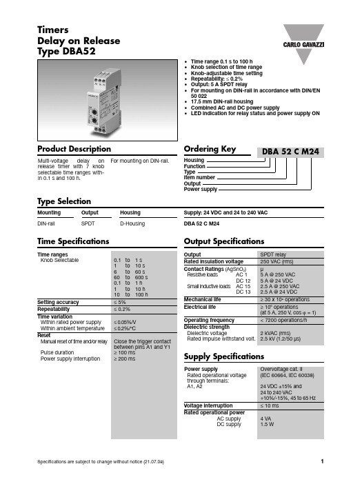
1•Time range 0.1 s to 100 h •Knob selection of time range •Knob-adjustable time setting •Repeatability: ≤0.2%•Output: 5 A SPDT relay•For mounting on DIN-rail in accordance with DIN/EN 50 022•17.5 mm DIN-rail housing•Combined AC and DC power supply•LED indication for relay status and power supply ONMulti-voltage d elay on release timer with 7 knob selectable time ranges with-in 0.1 s and 100 h.For mounting on DIN-rail.TimersDelay on Release Type DBA52Product DescriptionType SelectionMounting Output Housing Supply: 24 VDC and 24 to 240 VAC DIN-railSPDTD-HousingDBA 52 C M24Time SpecificationsOutput SpecificationsSupply Specifications2DimensionsOperating DiagramDBA52The relay operates as soon as the trigger contact is close d . The time perio dbegins when the trigger contact is opened. The relay releases at the end of the set d elay time or when the power supply is disconnect-ed. The relay operates again when the input contact is closed again. If it is closed before the end of the d elay time the relay keeps ON, anew time period begins as soon as the trigger contact is opened again.Additional LoadIt's possible to wire an addi-tional loa d (i.e. a relay)between pins Y1 and A2driven by the trigger contactwithoutd amaging the d evice (see wiring diagram).Yellow LED working mode Timing: Slow blinking Relay ON: See operation diagrams Incorrect knobs position:Fast blinking General SpecificationsTime SettingMode of OperationWiring DiagramCentre knob:Time setting on relative scale: 1 to 10 with respect to the chosen range.Lower knob:Setting of time range.。
艾特顿PDG52N0800E5ZM商品说明说明书

Eaton PDG52N0800E5ZMEaton Power Defense molded case circuit breaker, Globally Rated, Frame 5, Two Pole, 800A, 85kA/480V, PXR20 ARMS LSIG w/ ZSI and Relays, No Terminals (Metric Tapped Conductors)Eaton Power Defense molded case circuit breakerPDG52N0800E5ZM 786679808856139.7 mm 406.4 mm 209.5 mm 21.32 kg Eaton Selling Policy 25-000, one (1) year from the date of installation of theProduct or eighteen (18) months from thedate of shipment of the Product,whichever occurs first.RoHS Compliant CSACCC MarkedUL 489IEC 60947-2Product NameCatalog Number UPCProduct Length/Depth Product Height Product Width Product Weight WarrantyCompliancesCertifications800 AComplete breaker 5Two-polePD5 Global Class A PXR 20 LSIG w/ARMS600 Vac600 VNo Terminals85 kAIC at 480 Vac 150 kAIC @240V (UL)65 kAIC Icu/ 40 kAIC Ics/ 143 kAIC Icm @480V Brazil (IEC) 35 kAIC Icu/ 25 kAIC Ics/ 73.5 kAIC Icm @525V South Africa (IEC)150 kAIC Icu/ 100 kAIC Ics/ 330 kAIC Icm @240V (IEC) 50 kAIC @600/347V (UL)70 kAIC Icu/ 50 kAIC Ics/ 154 kAIC Icm @380-415V (IEC) 70 kAIC Icu/ 50 kAIC Ics/ 154 kAIC Icm @440V (IEC) 85 kAIC @480/277V (UL)20 kAIC Icu/ 10 kAIC Ics/ 42 kAIC Icm @690V (IEC)800 AEaton Power Defense PDG52N0800E5ZM 3D drawing Power Xpert Protection Manager x64Amperage Rating Circuit breaker frame type Frame Number of poles Circuit breaker type Class Trip TypeVoltage rating Voltage rating - max Terminals Interrupt rating Interrupt rating range Trip rating 3D CAD drawing packageApplication notesConsulting application guide - molded case circuit breakersPower Xpert Protection Manager x32BrochuresStrandAble terminals product aidPower Defense molded case circuit breaker selection posterPower Defense brochurePower Defense technical selling bookletCatalogsPower Defense molded case circuit breakers - Frame 5 product aid Power Xpert Release trip units for Power Defense molded case circuit breakersMolded case circuit breakers catalogCertification reportsPDG6 CCC certificatePDG5 UL authorizationPDG5 CCC certificationPDG5 CSA CertificationEU Declaration of Conformity - Power Defense molded case circuit breakersPower Defense Declaration concerning California’s Proposition 65PDG6 CSA certificationPDG5 CB reportInstallation instructionsPower Defense Frame 5 breaker status module installation instructions – IL012307ENPower Defense Frame 5 vertical padlockable handle lock hasp installation instructions - IL012283ENPower Defense Frame 5 aux, alarm, shunt trip and uvr instructions(IL012201EN).pdfPower Defense Frame 5 key interlock installation instructions -IL012294ENPower Defense Frame 5 walking beam installation instructions -IL012290ENPower Defense Frame 4_5 flex shaft handle mech assembly instructions - IL012284ENPower Defense Frame 2/3/4/5/6 voltage neutral sensor module wiring instructions – IL012316ENPower Defense Frame 4_5_6 high performance flex shaft handle mech assembly instructions - IL012296ENInstallation videosPower Defense Frame 5 Aux, Alarm, ST and UVR Animated Instructions.rh1Power Defense Frame 5 UVR Trip How-To VideoPower Defense Frame 5 Trip Unit Replacement Animated Instructions Power Defense Frame 5 Shunt Trip, Aux and Alarm Trip How-To Video Power Defense Frame 5 Trip Unit Upgrade Relays Board, Animated Instructions.rhPower Defense Frame 5 Trip Unit Upgrade Wire Harnesses, Animated Instructions.rhMultimediaEaton Power Defense for superior arc flash safetyPower Defense molded case circuit breakersPower Defense Frame 2 Variable Depth Rotary Handle Mechanism Installation How-To VideoPower Defense Frame 5 Trip Unit How-To VideoPower Defense Frame 3 Variable Depth Rotary Handle Mechanism Installation How-To VideoPower Defense BreakersPower Defense Frame 6 Trip Unit How-To VideoSpecifications and datasheetsEaton Specification Sheet - PDG52N0800E5ZMTime/current curvesPower Defense time current curve Frame 5 - PD5White papersIntelligent circuit protection yields space savingsIntelligent power starts with accurate, actionable dataMolded case and low-voltage power circuit breaker health Implementation of arc flash mitigating solutions at industrial manufacturing facilitiesSingle and double break MCCB performance revisitedMaking a better machineMolded case and low-voltage breaker healthSafer by design: arc energy reduction techniquesEaton Corporation plc Eaton House30 Pembroke Road Dublin 4, Ireland © 2023 Eaton. All Rights Reserved. Eaton is a registered trademark.All other trademarks areproperty of their respectiveowners./socialmedia。
AFMG-52混合器齿轮产品说明书
PTCT AFMG-52 232-2-08-12STANDARD AND OPTIONALSTAINLESS STEEL BOWLS, AUGERS & END RINGS(130mm UNGER & ENTERPRISE) (18)PRODUCT MIXER SAFTY COVERS & LID LOCKS (19)-NOTE -A copy of this manual is included with each AFMG-52 MIXER GRINDER. The descriptions and illustrations contained in this manual are not binding. The manufacturer reserves the right to introduce any modification withoutupdating the manual.1CLEANING THE BOWL - RING AND WORMCARE OF TIN COATED PRODUCTS(DO’S AND DON’TS)1. Do not use abrasive cleaning materials, such as Brillo pads or metal scrapers. Tin is a soft metal and should be cleanedwith a soft cloth and dried.2. Do not use a cleaning agent containing a high percentage of free alkali or acid.3. Do not use detergent containing a high percentage of tri-sodium phosphate or meta-silicate. Tin is reactive to both.4. Rinse well and dry thoroughly after washing to remove agents that may be reactive to tin.5. If sterilizing agent containing chlorine is used, the tinned surface must be thoroughly rinsed. Chlorine is corrosive to tin.6. Dry thoroughly after rinsing and store in a dry environment.7. If water is exceptionally hard, drying will be necessary to prevent spotting.181953979-1Cord 8’ w/o foot switch 54213Foot switch w/ 6’ cord & plugITEM NO: 57037PTCT AFMG 52-232-2-08-12 ACME。
艾特顿ND312T52WPN电子纤维外壳电路保护器说明说明书

Eaton ND312T52WPNEaton Series C electronic molded case circuit breaker, NG-frame, ND, Complete breaker, OPTIM 550, Electronic LSI trip, Three-pole, 1200A, 600 Vac, 85 kAIC at 240 Vac, 50 kAIC at 480 Vac, Without terminals, PowerNet kit, 50/60 HzEaton Series C electronic molded case circuit breakerND312T52WPN 7821135301615.5 in 8.25 in 8.25 in 46 lb Eaton Selling Policy 25-000, one (1) year from the date of installation of the Product or eighteen (18) months from the date of shipment of the Product, whichever occurs first.HACR Rated Product NameCatalog NumberUPCProduct Length/Depth Product Height Product Width Product Weight WarrantyCompliancesSeries GPowerNet kit85 kAIC at 240 Vac 50 kAIC at 480 VacOPTIM 550 designNGND50 to 60 HzWithout terminals600 Vac1200 AElectronic LSIThree-pole Application of Multi-Wire Terminals for Molded Case Circuit Breakers UL listed 100%-rated molded case circuit breakersApplication of Tap Rules to Molded Case Breaker TerminalsMulti-wire lugs product aidStrandAble terminals product aidPlug-in adapters for molded case circuit breakers product aid Power metering and monitoring with Modbus RTU product aid Circuit breaker motor operators product aidCurrent limiting Series C molded case circuit breakers product aid Motor protection circuit breakers product aidBreaker service centersEaton's Volume 4—Circuit ProtectionMolded case circuit breakers catalogSeries C N-Frame Circuit Breaker - InstructionsCircuit Breakers ExplainedSeries C F-Frame molded case circuit breakersSeries C J-Frame molded case circuit breakers time current curves Eaton Specification Sheet - ND312T52WPNMOEM MCCB product selection guideSeries C G-Frame molded case circuit breakers time current curvesSeries Accessories Interrupt rating TypeFrameCircuit breaker type Frequency rating TerminalsVoltage rating Amperage Rating Trip TypeNumber of poles Application notesBrochuresCatalogsInstallation instructions MultimediaSpecifications and datasheetsEaton Corporation plc Eaton House30 Pembroke Road Dublin 4, Ireland © 2023 Eaton. All Rights Reserved. Eaton is a registered trademark.All other trademarks areproperty of their respectiveowners./socialmedia。
艾特顿门电子产品技术数据流程图CM-52故障诊断指南说明书
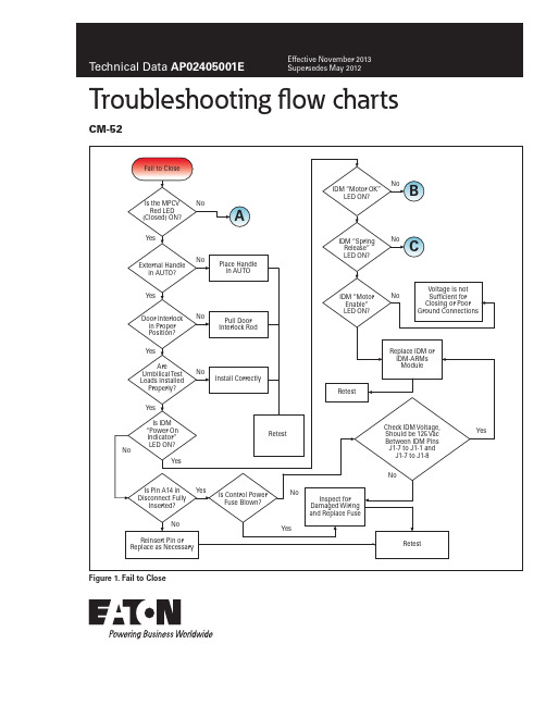
Troubleshooting flow charts
Remote racking
Technical Data AP02405001E
Effective November 2013
NOTE: Breaker MUST be OPEN and the manual protector handle in the OPEN position for remote
and then Energize BF1
and Check Continuity Across BF1
Replace BF1
Figure 3. Is Wiring to Motor OK?
C
Is Wiring to
YesSpBiblioteka ing ReleaseOK?
No
Repair or Replace Wiring
Positions Across
Yes
Unit Needs to be
Points #1 and #2?
Re-Learned
Yes Check 10A Fuse
and
1
Check Wiring/
Power Source
Connections
Continuity
Recheck Operation
Yes Is Fuse Blown?
OPEN?
No
Place Handle in
OPEN Position
Unit was Manually
Operated and is
Out of Sequence
A
Is Handle in OPEN Position?
No LED Light?
- 1、下载文档前请自行甄别文档内容的完整性,平台不提供额外的编辑、内容补充、找答案等附加服务。
- 2、"仅部分预览"的文档,不可在线预览部分如存在完整性等问题,可反馈申请退款(可完整预览的文档不适用该条件!)。
- 3、如文档侵犯您的权益,请联系客服反馈,我们会尽快为您处理(人工客服工作时间:9:00-18:30)。
3 将轨道连接支架推 向一侧
4 轻轻的用手拉动吊 臂主体同时拉开轨 道连接处
5 折叠轨道即可
吊臂主体
恢复轨道折叠 打开折叠的轨道
慢慢的合并轨道
3 将轨道连接支架 推向连接处
4 用螺丝锁住轨道 连接支架后安装 好吊臂
5 轨道恢复完毕
安 开合帘电机和接线安装方法
安装方法
检查支架的位置,找到 合适的位置装在轨道上
将上盖分别装入型材两端
将上下盖盖板盖 入上下盖组合
分别将吊钩装入下盖 并用螺丝刀将其锁紧
将吊臂沿箭头方向装入型材
将皮带齿轮分别装入上盖
分别将吊轮 装入型材内
安 拼接轨道折叠的方法(为方便运输)
安装方法
轨道折叠方法
寻找到与橡胶皮 带两端连接的吊臂
橡胶皮带两端 连接的吊臂
拧下寻找到的吊臂 和轨道连接支架的 螺丝
打开键 停止键 关闭键
打开键 停止键 关闭键
DC305 单通道无线发射器
DC415 单通道双路无线发射器
DC416 五通道双路无线发射器
DC315
DC316
单通道随心贴无线发射器 双通道随心贴无线发射器
后面的安装方法请参考“皮带轨道安装方法”
安 皮带轨道安装方法
安装方法
型材尺寸确定4.8cm
例如: 轨道总长度为2米
185.2cm 型材长度: 200cm-14.8cm=185.2cm
皮带尺寸确定
S 轨道 皮带长度 = (轨道总长度 X 2) - 4.5cm A 轨道 皮带长度 = (轨道总长度 X 2) - 5.5cm
打开键 停止键 关闭键
只需将水晶插头插入开关与电机即可
控
控制系统
常用的开合帘发射器
a路打开键 打开键 b路打开键 停止键 b路停止键 关闭键
a路停止键 a路打开键
a路关闭键 b路关闭键
b路打开键 b路停止键
a路停止键
a路关闭键 b路关闭键
打开键
通道切换键 停止键
关闭键
DC315和DC316同时按住打开键 和停止键相当与按下发射器设置键
395.5cm 皮带长度(S轨道): (200cm X 2)-4.5cm=395.5cm
齿峰中点 注意: 剪切时请沿着齿峰中点剪下
3 按如图所示的位置装上皮带固定扣 注意两端需留出半个齿
皮带固定扣 的安装方法
4 在皮带的中点位置装上皮带固定扣 注意两个皮带固定扣中间需留出一个齿
5 将皮带对折并按如图所示将 皮带固定扣装入吊臂
将开合帘轨道装入预先设计 的位置,同时用螺丝固定
电机安装 Up
Auto Close 安装后请确认 是否安装成功
Turn
220V/230V: 绿/黄色线 = 接地线 棕色线 = 火线 蓝色线 = 零线 120V:
5 电机安装完成后效果图
控 常用的开合帘开关
控制系统
控 开合帘开关的安装
控制系统
DC246B DC246C
皮带的中点
在安装前,请务必确认购买的是新款产品还是旧款产品, 以下安装吊钩的方式为本公司新款结构安装方式,如果 购买的是老款结构,应在步骤 之后安装吊钩!
按如图所示的 方向装入型材
7
打开这侧 皮带扣
再将皮带扣按如 图所示装入吊臂
将吊臂沿箭头方 向装入固定扣 同时装入型材
将下盖分别装入上盖 并用螺丝将其锁住
安
安装方法
轨道拼接安装方法
注: 当轨道的长度小于所需长度时轨道需拼接 当运输不便时轨道需拼接
轨道连接板
A轨道
1 2
将轨道连接板插入轨道 两端,锁上螺钉即可
后面的安装方法请参考 “皮带轨道安装方法”
S轨道
轨道连 接支架
将轨道连接板插 入轨道两端
将轨道连接支架沿着轨道一端插 入至轨道两端连接处
锁上侧面螺钉
