仪表阀门说明书
美标阀门型号说明书[2]
![美标阀门型号说明书[2]](https://img.taocdn.com/s3/m/d4a5af81172ded630b1cb6c9.png)
实用文档1.4阀门及小型设备代号解释1.4.1闸阀(GATE VALVE)、截止阀(GLOBE VALVE)止回阀(CHECK VALVE)、针型阀(NEEDLE GLOBE VALVE) - / 特殊代码(3位)见表1.4.1-8阀芯材质,见表1.4.1-7阀体材质,见表1.4.1-6连接型式,见表1.4.1-5接管壁厚,见表1.2.1-2*传动机构,见表1.4.1-4结构型式,见表1.4.1-3压力等级,见表1.4.1-2阀门类别,见表1.4.1-1 注*:只有“连接型式”中为BW时才有此项↑对CL900.1500.2500三个等级的阀门,一般采用压力密封阀盖,此时“阀盖垫片”和“阀盖螺栓”项缺省。
→等级1a、2a、3a、4a、5a适用于JB标准阀门。
注:←如果阀门的结构型式为“2”、“8”和“9”,即阀盖为压力密封阀盖,则该表中的“阀盖垫片材料”和“阀盖螺栓材料”栏缺省。
↑如果阀门的结构型式为“5”,则该表中的“阀杆填料”栏缺省。
表1.4.1-8,特殊代码1.4.2球阀(BALL VALVE)特殊代码(3位)见表1.4.1-8阀芯材质,见表1.4.2-2阀体材质,见表1.4.1-6连接型式,见表1.4.1-5接管壁厚,见表1.2.1-2*传动机构,见表1.4.1-4结构型式,见表1.4.2-1压力等级,见表1.4.1-2阀门类别:球阀/BALL VALVE,代号-Q1.4.3 旋塞阀(PLUG VALVE)阀芯材质,见表1.4.3-2阀体材质,见表1.4.1-6连接型式,见表1.4.1-5接管壁厚,见表1.2.1-2*传动机构,见表1.4.1-4结构型式,见表1.4.3-1压力等级,见表1.4.1-2阀门类别:旋塞阀/PLUG VALVE,代号-P1.4.4 蝶阀(BUTTERFLY VALVE)阀芯材质,见表1.4.4-2阀体材质,见表1.4.1-6连接型式,见表1.4.1-5接管壁厚,见表1.2.1-2*传动机构,见表1.4.1-4结构型式,见表1.4.4-1压力等级,见表1.4.1-2阀门类别:蝶阀/BUTTERFLY VALVE,代号-D1.4.5 疏水阀(STEAM TRAP VALVE)阀芯材质,见表1.4.5-2阀体材质,见表1.4.1-6连接型式,见表1.4.1-5结构型式,见表1.4.5-1压力等级,见表1.4.1-2阀门类别:疏水阀/STEAM TRAP VALVE,代号-S1.4.6 过滤器(STRAINER)阀体材质,见表1.2.1-3连接型式,见表1.4.1-5接管壁厚,见表1.2.1-2*结构型式,见表1.4.6-1压力等级,见表1.3.1-2阀门类别:过滤器(STRAINER),代号-T 阀芯材质一般为3041.4.7视镜(SIGHT GLASS)阀体材质,见表1.2.1-3连接型式,见表1.4.1-5接管壁厚,见表1.2.1-2*结构型式,见表1.4.7-1压力等级,见表1.3.1-2阀门类别:视镜(SIGHT GLASS),代号-G 注*:只有“连接型式”中为BW时才有此项1.4.8仪表测压阀(Y)接管材质,见表1.4.8-3阀芯材质,见表1.4.1阀体材质,见表1.2.1-3近主管接管长度,见表1.4.8-2接管壁厚,见表1.2.1-2压力等级,见表1.3.1-2主阀类型,见表1.4.8-1阀门类别:仪表测压阀,代号-Y。
西安汇源仪表阀门 SXDF系列 双向直动式电磁阀 说明书

双向直动式电磁阀SXDF-8~100系列常闭式SXDF-8K~100K 系列常开式BSXDF-8~100系列防爆型一、产品概述SXDF-8~100系列直动式双向电磁阀是我公司工程技术人员在参改国外同类产品的基础上自发研制成功的一种多功能高技术的自控阀门。
该产品具有结构紧凑,动作灵敏,性能可靠,特别是介质方向可任意流动,解决了目前国内外绝大多数电磁阀只允许介质单向流通的难题,可适用于工业及民用自控领域对管道中的介质进行快速切断及远程控制。
二、主要特点1、工作介质或正反方向流动:由于采用进出口平衡结构,介质压力互相抵消,故电磁阀可实现正反方向正常工作。
2、介质范围广:由于采用直动式,使用介质不需先导孔调整,故可实现气体、液体及各种油类同时使用。
3、无压差工作:由于电磁阀动作不受工作介质压力影响,只靠电磁铁吸力及复位弹簧共同作用。
故工作可靠、安全、迅速。
4、可直接用于真空管道中:由于采用了软密封方式,介质压力与复位弹簧力可均作用于阀口,所以关闭严密,内外泄漏量均高于行业标准最高要求。
5、流通面积大:易于克服通道结疤、堵塞等弊端。
三、工作原理当电磁线圈通电时,电磁铁产生吸力,克服弹簧力。
由于阀塞上、下介质压力相等互相抵消,故阀塞不受介质压力影响。
在铁芯的拉力作用下,阀塞被推离阀口,使阀门开启。
当电磁铁线圈断电后,同样阀塞处于平衡状态,电磁铁吸力消除,阀塞在复位弹簧力的作用下推到密封阀座上,使阀门紧密关闭。
四、主要技术参数公称通径 8 10 15 20 25 32 40 50 65 80 100连接方式 G1/4 G3/8 G1/2 法兰 G3/4法兰G1″法兰G11/4法兰G11/2法兰G2″ 法兰 四孔法兰 四孔法兰八孔法兰公称压力 1.6Mpa 介质压力 +1.0Mpa~ -0.8Mpa +0.8Mpa~ -0.6Mpa 工作温度 5℃~80℃ (特殊-20℃~+150℃)环境温度 -20℃~+60℃工作电压 AC220V 380V 110V DC24V 220V线圈功耗 70W 80W 120W 150W 防爆等级 ExdIICT4 适用介质 气体 燃气 水 轻油开关时间 ≤1S材 质 不锈钢 铸铁、铸钢、不锈钢螺纹式结构图(1)螺纹式外形尺寸(单位:mm )型号规格SXDF-8B SXDF-10B SXDF-15B SXDF-20 SXDF-25SXDF-32SXDF-40SXDF-50 备 注 连接方式 G 1/4″/G 3/8″/G 1/2″G 3/4″ G 1″ G11/4″ G11/2″ G2″长(L ) 69 73 100 115 120 168 宽(A ) 80 80 80 86 95 125 高(H ) 185 195 218 270 275 295 常开型高度增加40mm防爆型高度 增加35mm宽度加40mm(2)法兰型外形尺寸(单位:mm )型号规格 SXDF-15BF SXDF-20BF SXDF-25BF SXDF-32BF SXDF-40BFSXDF-50BF 备 注 连接方式 4孔法兰 4孔法兰 4孔法兰 4孔法兰 4孔法兰 4孔法兰 长(L ) 110 110 140 148 148 195 宽(A ) 95 105 115 135 145 160 高(H ) 225 235 260 335 340 360常开型高度增加40mm防爆型高度增加35mm(3)大口径法兰型外形尺寸(单位:mm )型号规格 SXDF-65FSXDF-80F SXDF-100F SXDF-125F SXDF-150F SXDF-200F 备 注 连接方式 4孔法兰 4孔法兰 4孔法兰 4孔法兰 4孔法兰 4孔法兰 长(L ) 290 310 350 400 480 600 宽(A ) 185 200 220 250 285 340 高(H ) 450 480 520 600 650 680 常开型高度增加40mm防爆型高度增加35mm H六、安装使用注意事项1、电磁阀安装时应选择振动较小的水平管道锻为宜,尽量远离弯道处,以防止水锤对阀芯的冲击。
仪表专业阀门定位器操作维护规程
仪表专业阀门定位器操作维护规程一、概述阀门定位器是调节的主要附件,它与气动调节阀配套使用,接受调解器(包括DCS 或P1.G的调节回路)、气动仪表或电气转换器的输出信号,然后输出气信号去控制气动调节阀,当调节阀动作后,阀的阀位又通过机械装置反馈到阀门定位器,从而使阀门的位置能按调节器输出的控制信号进行正确定位。
阀门定位器的产品按其结构形式和工作原理可以分成电气阀门定位器、气动阀门定位器和智能阀门定位器。
电气阀门定位器能够起到电气转换器和气动阀门定位器的两种作用。
阀门定位器能够增大调节阀的输出功率,减少调节信号的传递滞后,加快阀杆的移动速度,能够提高阀门的线性度,克服阀杆的摩擦力并消除不平衡力的影响,从而保证调节阀的正确定位。
通用型阀门定位器可用于弹簧抚慰型(但动作型)执行器及双动作型执行器,反馈方式通常有直行程和角行程之分,一般均能实现正、反作用的任务选择,反馈凸轮特性有线性、等百分比等特性选择。
智能型电气阀门定位器性能稳定、调校方便;有自动校准系统和HART协议通讯功能;能实现与DCS、现场总线控制系统直接通讯,具备强大自诊断功能及其他扩展功能,控制更精确、稳定,维修简单。
二、电气、气动阀门定位器以KOSOEP800系列阀门定位器为例。
1技术标准(1)气源:净化空气额定压力0.14-0.7MPa(具体以有关产品说明书为难)。
(2)输入信号:4〜20mADC(电气定位器)或20〜IOOKPa(气动定位器)。
(3)输出信号:0.02-0.IMPa或0.04-0.2MPa,最大输出可到100%气源压力(双动作型阀门定位器除外)。
(4)灵敏度:0.1%。
(5)环境温度:-20〜80℃。
(6)电气阀门定位器绝缘电阻:〉20MΩo(7)基本误差:±1机(8)回差:1%。
2检查校验(1)校准仪器1) a.电流信号发生器1台2) b.气动定值器1台3) c.校准压力表2台(2)定位器的检查校验一般应在调节阀(或执行器)检查校验合格、定位器与调节阀装配好后进行。
asco阀门安全仪表系统用电磁阀使用手册-iec 61508说明书

I&M V 9629 R6 Solenoid Valves used in SafetyInstrumented SystemsASCO Valves ®Page 1 of 7Table of Contents1 I ntroduction (3)1.1 Terms and Abbreviations (3)1.2 Acronyms (3)2 Designing a Safety Instrumented Function using an ASCO Solenoid Valve (4)2.1 Safety Function (4)2.2 Environmental limits (4)2.3 Application limits (4)2.4 Design Verification (4)2.5 SIL Capability (5)2.5.1 Systematic Integrity (5)2.5.2 Random Integrity (5)3 Installation and Commissioning (5)3.1 Installation (5)3.2 Response Time (6)4 Operation and Maintenance (6)4.1 Proof test without automatic testing (6)4.2 Proof test with automatic partial valve stroke testing (6)4.3 Repair and replacement (7)4.4 ASCO Notification (7)5 ASCO Solenoid Pilot Valves Covered (7)6 Status of the document (7)6.1 Releases (7)1 IntroductionThis Operating Manual provides the necessary information to design, install, verify and maintain a Safety Instrumented Function (SIF) utilizing an ASCO Solenoid Valve. This manual provides necessary requirements for meeting the IEC 61508 or IEC 61511 functional safety standards.1.1 Terms and Abbreviations• Process Valve Any valve that is used to control the flow of media being used in a process.For the purpose of this document, this is usually a 2-way valve whosemovement is being controlled by an actuator and pilot valve.• Pilot Valve A 3-way or 4-way valve that is used to send or remove pressurized mediato and from an actuator for the opening and closing of a process valve.• Direct Acting Refers to a solenoid valves main orifice that is opened and closed as adirect result of the solenoid valves electromagnetic movement when thecoil is energized and de-energized.• Indirect Acting Refers to a solenoid valve’s main orifice that is opened and closed as aresult of fluid flow being directed from the electromagnetic 3-way solenoidpilot.• Safety Freedom from unacceptable risk of harm• Functional Safety The ability of a system to carry out the actions necessary to achieve or tomaintain a defined safe state for the equipment / machinery / plant /apparatus under control of the system• Basic Safety The equipment must be designed and manufactured such that it protectsagainst risk of damage to persons by electrical shock and other hazardsand against resulting fire and explosion. The protection must be effectiveunder all conditions of the nominal operation and under single faultcondition• Safety Assessment The investigation to arrive at a judgment - based on evidence - of thesafety achieved by safety-related systems• Fail-Safe State The state where the solenoid is de-energized and its return spring holdsthe pilot in the closed position.• Fail Safe Failure that causes the valve to go to the defined fail-safe state without ademand from the process.• Fail Dangerous Failure that does not respond to a demand from the process (i.e. beingunable to go to the defined fail-safe state).• Fail Dangerous Undetected (DU) Failure that is dangerous and that is not being diagnosed byautomatic stroke testing.• Fail Dangerous Detected (DD) Failure that is dangerous but is detected by automatic stroke testing.• Fail No Effect Failure of a component that is part of the safety function but that has noeffect on the safety function.• Low Demand Mode Mode, where the frequency of demands for operation made on a safety-related system is no greater than twice the proof test frequency.1.2 Acronyms• FMEDA Failure Modes, Effects and Diagnostic Analysis• HFT Hardware Fault Tolerance• MOC Management of Change: These are specific procedures often done whenperforming any work activities in compliance with government regulatoryauthorities.• PFD AVG Average Probability of Failure on Demand• SFF Safe Failure Fraction, the fraction of the overall failure rate of a device thatresults in either a safe fault or a diagnosed unsafe fault.• SIF Safety Instrumented Function, a set of equipment intended to reduce therisk due to a specific hazard (a safety loop).• SIL Safety Integrity Level, discrete level (one out of a possible four) forspecifying the safety integrity requirements of the safety functions to beallocated to the E/E/PE safety-related systems where Safety Integrity Level4 has the highest level of safety integrity and Safety Integrity Level 1 hasthe lowest.• SIS Safety Instrumented System – Implementation of one or more SafetyInstrumented Functions. A SIS is composed of any combination ofsensor(s), logic solver(s), and final element(s).2 D esigning a Safety Instrumented Function (SIF) using an ASCOSolenoid Valve2.1 Safety FunctionWhen de-energized, the ASCO Solenoid Pilot Valve moves to its fail-safe position. Depending on the solenoid specified Normally Closed (NC) or Normally Open (NO), the valve will supply the fluid media or vent the fluid media depending on the piping of the installation. Please note that the solenoid pilot valve must be piped to the actuator in accordance with the manufacturer’s recommendations and allowable desired function.The valve is intended to be part of final element subsystem as defined per IEC 61508 and the achieved SIL level of the designed function must be verified by the designer.2.2 Environmental limitsThe environmental limits of each solenoid are specified in the products respective catalog and Installation & Maintenance Instructions. The designer of a SIF must check that the product is rated for use within the expected environmental limits.2.3 Application limitsThe application limits of an ASCO Solenoid are specified in the products respective catalog and Installation & Maintenance Instructions. It is especially important that the designer check for material compatibility considering on-site chemical contaminants and air supply conditions. If the solenoid valve is used outside of the application limits or with incompatible materials, the reliability data provided becomes invalid.2.4 Design Verification• A detailed Failure Mode, Effects, and Diagnostics Analysis (FMEDA) report is available from ASCO.This report details all failure rates and failure modes as well as the expected lifetime.•The achieved Safety Integrity Level (SIL) of an entire Safety Instrumented Function (SIF) design must be verified by the designer via a calculation of PFD avg considering redundant architectures, proof test interval, proof test effectiveness, any automatic diagnostics, average repair time and the specific failure rates of all products included in the SIF. Each subsystem must be checked to assure compliance with minimum hardware fault tolerance (HFT) requirements. The Exida exSILentia tool is recommended for this work.•When using an ASCO Solenoid in a redundant configuration, a common cause factor of 5% should be included in safety integrity calculations.•The failure rate data listed the FMEDA report is only valid for the useful life time of an ASCO Solenoid.The failure rates will increase sometime after this time period. Reliability calculations based on the data listed in the FMEDA report for mission times beyond the lifetime may yield results that are too optimistic, i.e. the calculated Safety Integrity Level will not be achieved.2.5 SIL Capability2.5.1 Systematic IntegrityThe product has met manufacturer design process requirements of Safety Integrity Level (SIL) 3. These are intended to achieve sufficient integrity against systematic errors of design by the manufacturer. A Safety Instrumented Function (SIF) designed with this product must not be used at a SIL level higher than the statement without “prior use” justification by end user or diverse technology redundancy in the design.2.5.2 Random IntegrityThe solenoid valve is a Type A Device. Therefore when used the only component in a final element subassembly, a design can meet SIL 3 @ HFT=1 and SIL 2 @ HFT=0.When the final element assembly consists of many components (solenoid valve, quick exhaust valve, actuator, isolation valve, etc.) the SIL must be verified for the entire assembly using failure rates from all components. This analysis must account for any hardware fault tolerance and architecture constraints.3 Installation and Commissioning3.1 Installation•The ASCO Solenoid valve must be installed per standard installation practices outlined in the Installation Manual.•The environment must be checked to verify that environmental conditions do not exceed the ratings.•The ASCO Solenoid must be accessible for physical inspection.•Instrument Air Filtration: These solenoids are intended for use on clean, dry air or inert gas filtered to50 microns or better. To prevent freezing, the dew point of the media should be at least 18°F(10°C)below the minimum temperature to which any portion of the clean air or gas system could be exposed.Instrument air in compliance with ANSI/ISA Standard S7.3-1975 (R1981) exceeds the above requirements and is, therefore, an acceptable medium for these valves.• It is the operator’s responsibility to only use design options such as latches, when it is safe to do so.• Typical 3-way pilot valve piping configurations:a. 1 out-of 1 – This is the most common pilot valve configuration used.b. 2 out-of 2 – This is commonly used for high availability applications. In the case that onesolenoid valve was to spuriously trip, the second solenoid still maintains the position of theactuator/process valve at its operating state. Both solenoids must close in order to shift theactuator/process valve to its non-operating state.3.2 Response TimeThe response time of a solenoid pilot valve will vary by design. The factors that affect response time are pilot valve orifice size, operating pressure, size of actuator, torque required to open and close process valve, and distance between pilot valve and actuator. It is the responsibility of the end user to use a pilot valve that delivers the correct opening and closing time of the process valve required for the application.4 Operation and Maintenance4.1 Proof test without automatic testingThe objective of proof testing is to detect failures within an ASCO Solenoid that are not detected by any automatic diagnostics of the system. Of main concern are undetected failures that prevent the safety instrumented function from performing its intended function.The frequency of proof testing, or the proof test interval, is to be determined in reliability calculations for the safety instrumented functions for which an ASCO Solenoid is applied. The proof tests must be performed more frequently than or as frequently as specified in the calculation in order to maintain the required safety integrity of the safety instrumented function.The following proof test is recommended. Any failures that are detected and that compromise functional safety should be reported to ASCO.Table 11Bypass the safety PLC or take other appropriate action to avoid a false trip, following company Management of Change (MOC) procedures2Inspect the external parts of the solenoid valve for dirty or clogged ports and other physical damage. Do not attempt disassembly of the valve.the 3De-energize the solenoid coil and observe that the actuator and valve move. Energize solenoid after a small movement of the valve.4Inspect the solenoid for dirt, corrosion or excessive moisture. Clean if necessary and take corrective action to properly clean the air supply. This is done to avoid incipient failures due todirty air.5Record a n y failures i n your c o m p a n y’s S I F i n s p e c t i o n d a t a b a s e. Restore the loop t o full operation.6Remove the bypass from the safety PLC or otherwise restore normal operationThis test will detect approximately 99% of possible DU failures in the solenoid (Proof Test Coverage).The person(s) performing the proof test of an ASCO Solenoid should be trained in SIS operations, including bypass procedures, solenoid maintenance and company Management of Change procedures. No special tools are required.4.2 Proof test with automatic partial valve stroke testingAn automatic partial valve stroke testing scheme that performs a full stroke of the solenoid valve and measures valve movement timing will detect most potentially dangerous failure modes. It is recommended that a physical inspection (Step 2 from Table 1) be performed on a periodic basis with the time interval determined by plant conditions. Maximum inspection interval is five years but an annual inspection is recommended.4.3 Repair and replacementAccording to section 7.4.7.4 of IEC 61508-2 a useful lifetime based on experience, should be assumed. General field knowledge suggests that most solenoid valves have a useful life of 3 to 10 years, but may be longer depending on the valve series and other factors.It is the responsibility of the end user to establish a preventative maintenance process to replace all solenoids before the end of the useful life.4.4 ASCO NotificationAny failures that are detected and that compromise functional safety should be reported to ASCO Valve. Please contact ASCO customer service.5 ASCO Solenoid Pilot Valves CoveredSelect ASCO valves from the following series have been evaluated per IEC 61508 parts 1 and 2 and covered under this document:∙8314 Series - 3-Way Direct Acting Pilot Valves∙8320 Series - 3-Way Direct Acting Pilot Valves∙8316 Series - 3-Way Indirect Acting Pilot Valves∙551, 552, 553 Series - 3 and 4-Way Indirect Acting Pilot Valves∙8317, 8320, 8321 Series - 3-Way Harsh Environment Pilot Valves∙327/8327 Series - 3-Way Direct Acting Pilot Valves.∙126 Series - 3-Way Direct Acting Pilot Valves.∙8317 Series – 3-Way Piloting Quick Exhaust valve∙307 Series - 3-Way Direct Acting Pilot Valves∙364 Series – 3-Way Spool Valves∙362/562 Series – 3-Way and 4-Way Spool Valves6 Status of the document6.1 ReleasesRevision: GECN Number: 264756Release status: V9629 Initial Release on 02/18/11。
智能阀门定位器说明书

此界面是参数设定状态的第一界面。项号10表示直行程执行器。如果执行器为角行程执行器,则用户按向上键进入下一界面,表示角行程执行器。按向下又回到直行程执行器设定界面。退出执行器类型设定界面,按功能 + 向上键,进入执行器正/反作用设定界面。执行器类型则为退出时界面设定的状态。
2.1.3 位置变送电流输出模块报警及限位传感器模块
2.1.5 气动连接模块
02
气动连接
2-1-5 外接气源示意图
行器进气排气流量调节
1为执行器进气流量调节阀, 2为执行器出气流量调节阀
01
单作用及双作用执行器作用压力输入口Y1 位置反馈作用连杆 供气动力气源输入口Dz 具有消音作用的消耗气体排出口E
设定方法与定位器类型设定相同。项号11为正作用/反作用设定界面。按功能+向上键,系统退出执行器正/反作用设定,进入阀门气开气关设定界面。按功能 +向下键 进入10号菜单。以下所有菜单的转化以此类推,不再重复说明。 正作用表示4—20mA对应于0—100%行程。 反作用表示4—20mA对应于100—0%行程。
3.5.2.3 阀门定位器参数设定及初始化操作 1. 执行器类型设定:直行程/角行程,系统默认为直行程。 2.执行器正/反作用设定。默认为正作用
阀门气开、气关特性设定 气开型阀门设定,项号为12 型阀门设定,项号为12 特性曲线设定 定
2.1.1 主板
定位器当前位置通过2线制4~20mA输出反馈。一个数字输出表示一组故障信息,这两个报警输出电路与其他电路是隔离的。两个可调整限位位置的数字量输出通道。 2.1.4 现场总线扩展模块 在现代仪器仪表中现场总线技术的应用越来越广泛。然而,由于现场总线的多样性和复杂性,因此为了适应不同的系统就要配置不同的现场总线系统:PROFIBUS 、INTERBUS、CANBUS 总线、FF 总线、HART 总线。目前,我们能够提供HART总线通讯选择板卡。
天津百利二通电器 BFA 型 阀门电动装置控制 说明书

BFA型阀门电动装置控制器使用说明书天津百利二通电器有限公司概述BFA型电动阀门控制器是与阀门电动装置配套使用的产品,也是一种用以远距离控制电动阀门的仪表装置,用以控制电动阀门的开启和关闭。
根据实际工作情况,可以设置不同的功能,满足不同用户的要求。
特点:△ 体积小、结构简单、安装接线方便;△ 采用小型轻触按钮,灵敏可靠,寿命长;△ 小型开度表,指示准确,调整方便;△ 具有多功能特点,可根据不同要求增、减功能要求;技术指标:电源电压:380V、AC、50Hz三相四线制。
控制电压:220V、AC、50Hz。
环境温度:-20%~40℃相对湿度:≤90%(20±5℃时)周围不含有强腐蚀性、易燃、易爆介质。
外形及安装尺寸:外型尺寸160(长)×80(宽)×295(深)mm柜屏安装时开孔尺寸 152(长)×76(宽)mm工作原理简介:控制器的电路由主电路,控制电路,指示电路三部分组成,原理见附图。
按下“电源”按钮,接通电源。
按下“选择”按钮,选择现场与远控工作方式。
弹起为远控(控制器上)操作方式,远控指示灯亮;按下为现场操作方式,现场指示灯亮,此时控制器上开阀、关阀按钮不起作用。
按下“开阀”按钮,交流接触器KO吸合,电气自锁,阀门向开阀方向运行,直至阀门运行到全开位置,开向行程开关(常闭)断开,电机停止运行。
开向行程开关(常开)闭合“阀开”红色指示灯亮;按下“关阀”按钮,交流接触器KC吸合,电气自锁,阀门向关阀方向运行,直至阀门运行到全关位置,关向行程开关(常闭)断开,电机停止运行。
关向行程开关(常开)闭合“阀关”绿色指示灯亮。
在阀门向开或关方向运行过程中,如需要停止运行,可按下“停止”按钮可立即终止运行。
阀门在开或关运行过程中(或在开始启动时),如果超过控制转矩,开方向转矩开关或关方向转矩开关断开,电机停止运行。
“转矩”指示灯亮,(红色)。
在开阀或关阀过程中,如果电机温升过高或电流过大,电动装置电动机内热保护元件动作或控制器内热继电器动作,电机停止转动。
控制阀操作说明书(DOC)

MASONEILAN21000系列控制阀操作手册(中文版)二○○三年目录调节阀代码注释 (2)1 引言 (3)2 概述 (3)3 拆除 (3)4 安装 (3)5 送气管道 (4)6 阀体拆卸 (4)6.1 螺纹阀芯 (4)6.2 速换阀芯 (5)7 维修/检修 (6)7.1 螺纹基座拆除 (6)7.2 套管拆除 (6)7.3 研磨基座 (6)7.3A 螺纹阀芯…………………………………………………7.3B 速换阀芯…………………………………………………7.4 逻辑双重端阀……………………………………………………7.5 阀芯轴插杆………………………………………………………7.6 包装箱(标准) ……………………………………………………7.7 包装箱(润滑) ……………………………………………………7.8 软基座活塞………………………………………………………8 阀体再组装……………………………………………………………8.1 螺纹微调…………………………………………………………8.2 速换微调…………………………………………………………9 附图……………………………………………………………………模型序号图1尺寸和比率图21 引言在安装、运行和维修该设备之前,应全面审查并理解下列指南。
在整篇文章中,都有安全和警告注意事项,必须严格坚持,否则,会造成严重损坏或者设备失灵。
Masoneilan在非常熟练的服务工程师,他们广泛应用于阀门和部件的运行、维修和检修。
另外,还进行常规的培训计划以培训我们的阀门及仪表的操作、维修和应用的客户服务与仪表人员。
通过你们的Masoneilan代表或者地区办公室,进行这些服务的安排。
在进行维修时,只用Masoneilan的更换部件。
可以通过当地的Masoneilan代表或者地区办公室购买部件。
订购部件时,通常包括检修机组的模型和系列号。
2 概述安装和维修指南应用于Masoneilan 21000系列控制阀的所有尺寸和比率,不管使用的微调类型。
阀门定位器说明书

—1—
图 1 智能阀门定位器原理框图
2.1 功能介绍
自适应功能:自动寻找阀门零点和满度,优化阀门控制参数, 提高控制精度 组态功能: 可设置阀门特性曲线、动作方式、死区、行程范围、关断值、事件输出 自诊断功能:能显示输入电流值、上/下行程时间、死区、预判值等 故障模式:故障时定位器可选择 全开、全关、保持、手动等模式 通讯功能:HART 协议的通讯功能 电流反馈功能:输出 4~20mADC 阀位反馈信号
3 技术参数
气指标 输入输出
气源压力 阀泄漏量 稳态耗气量 适应执行机构 行程范围 电流输入 反馈输出
0.14~0.7 Mpa < 0.6L / H < 36L / H
单作用、双作用 直行程 10~100mm;角行程 30~120º 4~20mA DC,最小输入电流>3.6mA;可设定分程控制起点和终点
1 用户须知
1.1 安全指示
定位器先上电,后供气源; 产品使用过程中,不要随意的触摸反馈连接装置; 产品必须正确安装、正确操作和正确维护。
1.2 开箱清单
智能阀门定位器; 安装配件; 用户手册; 另外订制附件,详见装箱清单。
1.3 重要信息提示
为了您能更好地应用这份说明,以及保障你在调试,运行和维修这台仪器时的安全,请注意下列符
智能电气阀门定位器
用户手册
1 用户须知 ...................................................................................................................................................... 1
梅索尼兰阀门说明书
阀门调试梅索尼兰是一种智能式的定位器,对该种气动阀的调试,首先对控制回路查线和接线方式确认,再次对仪表管道进行吹扫。
注意事项:在进行设置时必须从信号源输入4~20mA电流信号或者从HART(数字通信协议)输入,操作电源来自于4~20mA电流信号或者是12/24VDC电压等多支路供应。
当SVI阀门调节器或控制器没有按钮或者没有显示,如果要进行系统设置或校验,则必须用HART通信协议或者个人计算机上阀门软件来进行阀门参数设定。
该定位器又分为气开式(正作用式:4mA指令对应全关、20mA指令对应全开)、气关式(反作用式:4mA指令对应全开、20mA指令对应全关)和双气缸(厂家说:出厂是什么参数就是什么不需要更改什么参数)三种型号,梅索尼兰有一个简便操作接口、高精度的阀位执行机构、据有自动设置和调整功能。
所以我们首先要认识阀门的用户接口(interface),梅索尼兰有三个操作按钮,○1左边一个按钮上标有“*”字样,这个按钮允许我们进行选择或者确认被改的参数;○2中间这个按钮上标有“-”字样,这个按键允许我们从下一个菜单移到上一个菜单,或者对所修改的参数进行减操作;○3右边这个按钮上标有“+”字样,这个按键允许我们从上一个菜单移到下一个菜单,或者对所修改的参数进行加操作。
当我们首次调试时,第一个看到的画面是“POS…”,如果要调整该定位器,首先必须从“POS…”切换到手动位置,画面显示的是:“MAN POS”。
当阀门在自动位置时我们可以用以下方法进行切换。
首先按标记为“+”的键,只到阀门显示(→MAN)字样时,按“*”键就可以进入手动状态,在手动状态时阀门应显示(MAN POS)字样。
这时如果再按下“*”键,就可以进行手动操作该阀门。
如果想切换到自动位置时,只要该定位器显示(MAN POS)字样时,表示阀门现为手动状态。
这时我们只有按下“+”键,只到显示(→OPER)字样,这时按“*”键,阀门将会自动进入自动状态。
智能阀门定位器说明书

图 3.5.2.2.2
显示界面(见图3.5.2.2.2)。在未初始化状 态中,按 用于充气,按 用于放气。
2.参数设定、初始化状态 不论在未初始化状态界面,还是在正常运营界面,顾客只需同步按下:
+ + 三个键3秒钟就能够进入到参数设定和初始化状态。
3.正常运营状态 参数设定、初始化成功后,定位器系统自动进入运营状态。
6.调整阀门定位器位置,使阀门定位器到达最高点和最低点时,反馈连杆 摆动角度不超出允许范围。
7.阀门定位器旳进一步调整见3.5节“初始化及投入使用”。
3.3 电气连接
图3-2-2 安装图
阐明:在进行电气连接前确 保全部旳可选择模块已安 装好。
注意:在进行电气安装时, 请参见有关原则,尤其在 危险旳环境中更要根据危 险
智能阀门定位器阐明书
安全注意事项
1.智能阀门定位器简介
2.定位器旳构造
2.1 定位器旳单元构成
3.操作阐明
3.1 外型连接尺寸 3.2 安装 3.3 电气连接 3.4 气动连接 3.5 初始化及投入使用
4. 主要技术参数
5.维护注意事项
6.故障诊疗
返回
安全注意事项
在使用本定位器之前,请务必仔细阅读下面旳安全 注意事项。
2.执行器正/反作用设定。默以为正作用 设定措施与定位器类型设定相同。项号11为
正作用/反作用设定界面。按功能+向上键,系 统退出执行器正/反作用设定,进入阀门气开气 关设定界面。按功能 +向下键 进入10号菜单。 下列全部菜单旳转化以此类推,不再反复阐明。
正作用表达4—20mA相应于0—100%行程。 反作用表达4—20mA相应于100—0%行程。
单作用定位器压力测量模块涉及两个压力表,能够显示输入、输出 气体旳压力。
Fisher DVC2000系列数字式阀门控制器-中文详细说明书

快速使用指南资料号57892005年1月DVC2000系列FIELDVUE® DVC2000系列数字式阀门控制器手册简介安装基本设置和校验技术规格和相关资料注意该手册提供了DVC2000系列数字式阀门控制器的安装、初始设置和校验、以及维护信息。
获得更多的信息,你可以阅读从Fisher销售商那里获得的FIELDVUE®DVC2000系列数字式阀门控制器使用手册——资料号 5772,或者直接访问我们的网址:DVC2000系列展开这一页以查看“现场液晶界面流程图”DVC2000系列现场液晶界面流程图主屏TRAVEL=66.8% 14.6 MA 0.92 BAR停止仪表动作行程偏差检查装配检查输入气源检查I/P(输入/输出)转换器在预设屏幕上以下项目是用警告图标进行确认的12 3 4 5 6 7 8快速设置阀门会移动3秒种定位0%...定位100%...定位0%...定位50%...行程校验校验阀门会移动3秒种自动手动调整调整阀门会移动3秒种阀门会移动3秒种自动手动详细设置零控制信号阀压力单位BAR自动手动关开BARPSIKPA阀门会移动3秒种模拟输入校验输入4 mAmA(输入会改变)3秒种阀位变送器校验送4 mA或送20 mA保存并退出?按保存并退出不保存退出控制现场控制手动SP=xxx控制=xxx模拟式或数字式手动式定位100%...定位0%...定位50%...定位50%...移动阀门至100%行程处自动手动移动阀门至0%行程处自动整定进行中...自动整定完成自动整定失败使用手动整定整定C衰减保存并退出不保存退出保存并退出?按+5不确定-5专家C,D,E,F,GHI,J,K,L,M输入范围下限 4 mA输入范围上限 20 mA特性曲线线形4 mA...19 mA5 mA...20 mA快开线形等百分比用户设置输入20 mA保存并退出?按保存并退出不保存退出只有在安装了变送器硬件的情况下才有用11111DVC2000系列更换主板SWITCH1=打开SWITCH2=关闭FW:1,HW1:1TUNING=C 保护 OFF关开只有在安装了限位开关的情况下才有用快速设置完成校准完成校准失败保存并退出?按保存并退出不保存退出英语法语西班牙语德语意大利语日语汉语语言 取消(返回主屏幕)注意:按住 + 3到10秒种+ + +语言选择 + + +3到10秒种变送器4 mA 限位开关1 90%限位开关1关闭 90%限位开关2 10%限位开关2关闭 10%关开125%...-25%高于低于无效125%...-25%低于高于无效保存并退出?按阀门可能移动 3秒种不保存退出?按只有在安装了变送器硬件的情况下才有用只有在安装了限位开关硬件的情况下才有用1111111DVC2000系列安装□ 正确地把用于阀门的仪表安装到执行机构上。
ABB阀门定位器 EDP300--instruction(V1.0)说明书

电气连接
根据下列接线端子图以及设计要求进行相应的配线(一般只需+11,-12,+31,-32)
A 侧基本模块:
+11
-12
+31 -32
+41 -42
+51 -52
+81 -82
+83 -84
设定阀门开度阈值:当定位器的给定信号大于该参 数值时,定位器将通过彻底的排气或充气,在控制 模式下移动阀门到 100%,55.0 … 100%
选择 On 参数时,若给定信号为 100%,定位器将在 100%处持续进行调节,适用于阀门行程 100%不是 机械全开位的场合。选择 Off 参数时,若给定信号 为 100%,定位器将驱动阀门至机械全开位,并将 供气压力作用于阀门,以保证阀门完全打开。
EDP300 智能定位器
简明安装及操作说明书(V1.0)
ABB (中国)自动化有限公司 仪器仪表总部
Tel: 021 5048 0101
Fax: 021 6105 6992
HOT LINE: 8008190190
4006209919
气路连接
• 使用与定位器气源端口处标识的标准接口连接气源.
气源的要求:仪表气体(无油、无尘、无水,符 合DIN / ISO8573-1污染及含油三级标准,最大颗 粒直径< 5um,且含量<5mg/m3,油滴<1mg/m3。露 点温度低于工作温度10k)
阀门工作范围的下行程设置,只在自动控制中有效
设定阀门关度阈值:当定位器的给定信号小于该参 数值时,定位器将通过彻底的排气或充 气,在控制模式下移动阀门到 0%。,0 ... 45.0%
西门子进程仪器仪表档案-压力传感器压力、温度、流量和阀门仪表用户手册说明书
Siemens Process Instrumentation Pressure, Temperature, Flow and Valve Instrumention User Manual ArchivesPressure Transmitters•Mycro XTC Models 340A and 340G Absolute and Gauge Pressure Transmitter-Controllers (SD340A/G, Issue 1, 3/92) - PDF 4.4 MB •Mycro XTC Differential Pressure Transmitter-Controller (SD340D, Issue 3, 2/93) - PDF 4.4 MB•Mycro XTC Models 340E and 340F Flanged Pressure Transmitter-Controller (SD340E/F -1, Issue 1, 10/92) - PDF 4.3 MB•XTC Transmitters Series 341 Pressure Transmitters (UM341, Rev 2, July 1998) - PDF 890K•User's Manual for XTC Transmitters, Series 340 Pressure Transmitter-Controllers (UM340-1, Rev. 5; April 2000) - PDF 1.9MB•ITT Conoflow Seals for XTC Transmitters (PI34-6, Rev 1, July 1995) - PDF 1.5 MB•SITRANS P, Pressure Transmitters, DS Series (precedes DSIII) 7MF4032 Operating Instructions (C73000-B5676-C82-1) - PDF 1.5 MB •SITRANS P, Absolute pressure transmitter, DS Series (precedes DSIII) 7MF4232 Operating Instructions (C79000-B5676-C92-01, 1999) - PDF 1.3 MB•SITRANS P, Absolute pressure transmitter, DS Series (precedes DSIII) 7MF4332 Operating Instructions (C73000-B5676-C84-1, 1994) - PDF 2.7 MB•SITRANS P, Differential pressure and flow transmitter, DS series (precedes DSIII) 7MF4432 and 7MF4532 Operating Instructions (C73000-B5676-C86-1, 1994) - PDF 3.1 MB•SITRANS P, Level transmitter, DS Series (precedes DSIII) 7MF4632 Operating Instructions (C73000-B5676-C88-1, 1994) - PDF 2.0 MB •TUV approved - Critical Pressure Transmitters, Model 345 User Manual (UM345-1, Rev. 3; April 2005) - PDF 3 MBTemperature•User's Manual for XTC Series 343 Temperature Transmitters (UM343-1, Rev. 2; March 1999) - PDF 3.3 MB•User's Manual for XTC Transmitter Series 344 (UM344-2, Issue 1, August 1995) - PDF 954KFlow•Model 140 MX Meter Body, SSPH Fluidic Flowmeter (SD140-1, Issue 4, 9/93) - PDF 700 KB•Model 140 MX Parts Drawing (No. 15344-78, 12/92) - PDF 69 KB•Model 14 Meter Body for Thermal or Deflection Sensor SSPH Fluidic Flowmeter (SD14-1, Issue 1, 4/83) - PDF 1.1 MB•Model Series 141 and 142 Fluidic Flowmeters (SD141, Issue 2, 12/92) - PDF 1.2 MB•Model 14 Q/I Converter For Fluidic Flowmeter with Thermal Sensor (SD14-2, Issue 3, 8/91) - PDF 3.4 MB•Model 14 Signal Converter for Meter Body with Deflection Sensor (SD14-3, Issue 1, 7/83) - PDF 1.6 MB•Model 14CNB SSPH Fluidic Flowmeter, Signal Converter Noise Compensation Kit Instructions (15900-1, Issue 1, 7/84) - PDF 199 KB •Analog 2-Wire Flow Transmitter (SD15973-10, Issue 2, 10/94) - PDF 991 KB•XTC Transmitters Model 340S SteaMeter (UM340S-1, Rev 2, 7/97) - PDF 970 KB•XTC Transmitters Model 340W Venturi Flow Transmitter (UM340W-1, Issue 1, 10/96) - PDF 658 KBValve Instrumentation•Model 70 Motion Transmitter Valve Positioner (SD70-6, 7/73) - PDF 415 KB•Model 71 Valve Positioners (SD71, 9/82) - PDF 392 KB•Series 71, 72, Side-Mounted Valve Positioners (SD72, Issue 8, 4/90) - PDF 1.9 KB•Series 711, 721 Valve Positioners (SD721-1, 6/74) - PDF 378 KB•Model Series 750E I/P Electronic Valve Positioner (SD750E, Rev 3; Jan.1992) - PDF 907KB•Model Series 750P Pneumatic Valve Positioner (SD750P, Issue 4, 7/94) - PDF 2.4 MB•User's Manual, Series 760D ValvePAC™ Digital Valve Controller (UM760D-1, Rev. 1; October 1998) PDF 1.5 MB•Model 760D ValvePAC Easy Start Instructions (Issue 1, 12/99) - PDF 199 KB•Model 772R Current-To-Pneumatic Transducing System (SD772R, Issue 1, 11/89) - PDF 934 KB•Model 773D I/PAC Current-To-Pneumatic Transducer (SD773D-1, Issue 3, 7/97) - PDF 1.2 MB•Model 773F I/PAC Current-To-Pneumatic Transducer (SD773F-1, Issue 2, 7/97) - PDF 1.2 MB•Model Series 781 Pneumatic to Electric Transducer (SD781, Issue 5, 6/82) - PDF 1.6 MB•Series 785 Multi-Point P/I Transducer (SD785, Issue 1, 12/86) - PDF 1.1 MB。
世伟洛克 40G系列和40系列 一体式仪表球阀 说明书
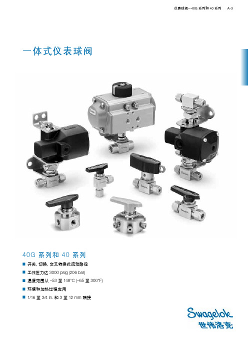
40G 系列和 40 系列■ 开关,切换,交叉转换式流动路径■ 工作压力达 3000 psig (206 bar)■ 温度范围从 –53 至 148°C (–65 至 300°F)■ 环境和加热过程应用■ 1/16 至 3/4 in . 和 3 至 12 mm端接一体式仪表球阀世伟洛克仪表球阀世伟洛克一体式仪表球阀多年来一直受到各个行业的广泛认可和采用。
原始的世伟洛克 40 系列和最新的 40G 系列阀门都可应用于多种执行机构、流动路径和手柄选购件,同时很容易进行在线填料调节。
有关世伟洛克仪表球阀的重要信息世伟洛克球阀设计用于全开或全 闭位置。
在一段时间内没有拧过的阀门可 能会有更高的初始执行扭矩。
在阀门的使用寿命期限内,可能 需要进行填料调节以防泄漏。
■ 使用说明书会随每个 40G 系列和 40系列阀附送。
■ 每个 40G 和 40 系列阀门都在1000 psig (69 bar) 的条件下进行氮气测试,如果低于1000 psig (69 bar),则在其额定压力下进行测试。
40系列阀门填料必须重新调整以便用在比测试压力高的场合。
有关标准产品测试,请参见第 P A-7页;有关选购件产品测试,请参见第P A-24页。
■ 安装之前暴露到动态温度条件下的仪表球阀可能会丢失其初始填料负载。
可能需要进行填料调整。
■ 41G 和 42G 系列阀门需要 8 mm 深井式套筒,43G 系列阀门需要 9 mm的深井式套筒,来调节填料螺栓。
■ 41 和 42 系列阀门需要 3/8 in. 开口扳手;44 系列阀门需要 1/2 in. 开口扳手;45 系列阀门需要 5/8 in. 开口扳手,来调节填料螺栓。
■ 43 系列阀门需要转换接头来调节填料螺栓。
订购号:MS-WK-4340G 系列和 40 系列比较➀活动负载 PFA (适用于所有尺寸)和UHMWPE ( 适用于41,42和43系列阀门的尺寸)填料可用于扩展至低温额定值 –53°C (–65°F)。
EPC380模块式智能阀门定位器使用说明书
EPC380模块式智能阀门定位器使用说明书1. 使用范围·适用执行器:供电电压380V±15%(AC), 与功率单元配套(接触器)控制开、关、停的电机。
·工作环境:环境温度:-20℃~75℃。
相对湿度:小于90%。
2.输入信号·调节输入信号:4~20mA(DC),输入负载阻抗小于150Ω。
·开度输入信号:电位器信号,500Ω~5KΩ。
3.输出信号·阀门位置反馈输出信号:4~20mA (DC,隔离),输出带负载能力不小于500Ω。
·开关控制信号:可控硅输出。
4.控制精度·灵敏度:在自动位置,灵敏度设定为自动调整方式另可手动设置灵敏度位置, 0.5%、1%、1.5%、2%、2.5%、3%、4%、5%共8挡。
5. 操作说明·标定:在手动位置,灯灭。
点动“开阀”键,电动阀门开向运行直至到开限位开关停止,此过程指示灯(红)慢闪烁,点动“关阀”键灯灭。
按住“开阀”键不松开5秒,阀全开指示灯(红)快闪烁以示确认,确认该位置为全开(满度)位置,抬起“开阀”键,满度标定过程结束。
此时指示灯(红)常亮。
点动“关阀”键,电动阀门关向运行直至到关限位开关停止,此过程指示灯(绿)慢闪烁,点动“开阀”键灯灭。
按住“关阀”键不松开5秒,阀全关指示灯(绿)快闪烁以示确认,确认该位置为全关(零点)位置,抬起“关阀”键,零点标定过程结束。
此时指示灯(绿)常亮。
·设置灵敏度位置:在自动位置,灵敏度设定为自动调整方式后,ΔP提前量值将由模块对目标自动计算得出并及时调整。
最终震荡次数不大于3次。
在手动设置灵敏度位置,ΔP提前量值将由模块对目标自动计算得出并及时调整。
灵敏度为手动设定值,最终震荡次数不大于3次。
当装置发生震荡时,手拨旋钮放大灵敏度到合适的档位。
ΔP:定义为电动阀门的控制误差,产生于电动阀门的电动装置的机械误差和电动装置电机断电后电动装置的惰走。
北方阀门说明书

12 1 P1 P2 P3 14 U 13
XK1
KZK,GZK THR MTH U OC,CC
KZK GZK
图中行程开关为阀门在中间位置时的状态,转矩开 关为电动装置输出转矩未超过设定控制转矩时的状态。
2 3
开关标识 接线脚编号 接线脚编号
OR,CR 控制开、关向运转继电器 TH FUSE XK XKA,XGA
1KXK
用户接线参考
无源触点组
XK1 操作状态开关(250VAC/15A),在XK C
A B
C
N 1
2
3
6
关 阀
8
开 阀
9
10 11
12 13 14
电容(50V/100μ)
V
整体型接线图 C221-8
9032~9035适用,24VDC
开度指示仪表电源
三相四线制 380VAC
天津市北方阀门控制设备公司
关
1GXK GZK
9 8 6
OR CR
注:
C + 24VDC
远控
断开
OR 2KXK CR 10 2GXK 11
符号说明:
用户接线端子
KXK,GXK
开、关向行程限位开关(250VAC/15A) 开、关向转矩控制开关(250VAC/15A) 空间加热电阻(220VAC) 埋在电机绕组内的温度保护开关 560W电位器 (阀门开向运行时P2 ,P3间电阻值增大) 控制开、关向运转接触器 热过载继电器 控制回路熔断器(0.5A) 现场/远控转换开关 开、关阀门现场操作开关 现场/远控开关处于“远控”状态时闭合
A B C N
动作程序
3
MTH CK XKA FUSE TH XK XGA OC1 CC
电动调节阀使用说明书

3
额定流量系数Krm /h
10
16
25
40
63 100 160 250 400 630 100 1600
公称压力PNMPa
1.6; 4; 6.4
0~10mA 配用执行
机构型号 4~20mA
DKZ-420 DKZ-430 ZKZ-320 ZKZ-330
DKZ-4200 DKZ-4300 ZKZ-3200 ZKZ-3300
电开关 电闭式
始点偏差 ±2.5%
±5%
终点偏差 ±5%
±2.5%
表4 额定行程偏差
±2.5% ±2.5%
泄漏量: 双座调节阀:不大于额定流量系数的5×10⁻³倍。
-4
单座调节阀:不大于额定流量系数的10 倍。 填料函及其它连接处的密封性:无渗漏。 耐压强度:在表5规定的试验压力下受压阀腔无渗漏。
图2 直通双座调节阀
图3 直通单座调节阀
第4页 共10页
BELL 天津贝尔自动化仪表技术有限公司
电动调节阀系列
六、外形尺寸及安装尺寸
1 ZAZP型电动单座调节阀的外形尺寸见图4及表8。(其它型号,执行机构部分参见相应说明书)
A
B1
B2
A
H 1'
H1
H2
H2
公称 通径 普通 带散热 DN 阀盖 片阀盖 H2 mm H1 H1'
阀门
伺服 放大器
位置 发送器
积分式执行机构
电动 操作器 动作切换
输入及正向 控制信号
反馈信号 机械联接
a 没 接 入 电 动 操 作 器
图 1
b 接 入 电 动 操 作 器
1 电动执行机构 电动执行机构的结构与工作原理见相应直行程电动执行机构使用说明书。 2 调节阀 调节阀与工艺管道中被调介质直接接触,阀芯在阀体内运动,改变阀芯与阀座之间的流通面积 即改变阀门的阻力系数就可以对工艺参数进行调节。 调节阀由上阀盖(或高温上阀盖)、阀体、下阀盖、阀芯与阀杆组成的阀芯部件、阀座、填料、 压板等组成。调节阀结构图见图2、图3。
- 1、下载文档前请自行甄别文档内容的完整性,平台不提供额外的编辑、内容补充、找答案等附加服务。
- 2、"仅部分预览"的文档,不可在线预览部分如存在完整性等问题,可反馈申请退款(可完整预览的文档不适用该条件!)。
- 3、如文档侵犯您的权益,请联系客服反馈,我们会尽快为您处理(人工客服工作时间:9:00-18:30)。
仪表阀门说明
仪表阀门是吸收国内外结构形式特点,根据使用场合不同,采用专门材质,特殊的结构形式,以达到合理使用。
这种仪表阀门具有连接牢固,密封可靠,安装拆卸方便等优点。
广泛用于石油、化工、燃气、轻工、电力、医药、冶金等装置系统。
QG·M1型压力表用球阀QG·QY1型气源球阀
连接尺寸
J J·M8型节流式仪表截止阀JJ·M1型压力表截止阀
连接尺寸
JJ·Y1型卡套式截止阀JJ·BY1型取压截止阀
连接尺寸
QG·Y1型卡套式球阀QG·AY1型取压球阀
连接尺寸
J11H(W)-160ⅢJ14H(W)-160ⅢJ24H(W)-160Ⅲ直通压力表截止阀角式压力表截止阀角式压力表截止阀
J29H-160 J29H-320压力计截止阀J49H-160 J49H-320压力计截止阀
连接尺寸
连接尺寸。
