PX-GL001A音频信号隔离器说明书
隔离器说明书

m XP 系列信号隔离器 co 概述 . XP 系列信号隔离器(一进一出,一进二出)是在自动化控制系统中对各种工业信号变送、转换、隔离、传输、运算的仪表,可 n 与各种工业传感器配合,取回参数信号,隔离变送传输,满足用户本地监视远程数据采集的需求。广泛应用于机械、电气、电信、 o 电力、石油、化工、钢铁、污水处理、楼宇建筑等领域的数据采集、信号传输转换、PLC、DCS 等工业测控系统,用来完善和补充 p 系统模拟∣/O 插件功能,增加系统适用性和现场环境的可靠度。 ur 特点 s 测量:直流电压、直流电流等 . 精度:≤±0.1%RO w 隔离:输入、输出、电源三方完全隔离,抗干扰能力强 w 电源:DC24V 或 AC220V w 支持带电热插拨装卸方便、精度高、线形度高、抗干扰性强、长期工作的稳定性
7(/
)$;
Model:XP-V-V010-A420-D Input: 0~10Vdc Output1:4~20mAdc Aux.power:DC24V 描述:此产品为一进一出信号隔离器,一路 0~10Vdc 直流电压信号输入,隔离变送输出一路 4~20mAdc 直流电 流信号;辅助电源为直流 24V.
苏州迅鹏仪器仪表有限公司
选型代码
苏州迅鹏仪器仪表有限公司
7(/
)$;
外形尺寸
95(L)*23(W) *120(H)mm
XP系列信号隔离器
35mm 导轨卡装;主机与底座可以插拔分离
接线图
www.surpon.com
常用规格实例
Model:XP-A-A420-2A420-D(等同于 XP-A-A420-A420A420-D,可以简写成 XP-A-A420-2A420-D) Input: 4~20mAdc Output1:4~20mAdc ; Output2:4~20mAdc Aux.power:DC24V 描述:此产品为一进二出信号隔离器,一路 4~20mA 直流信号输入,隔离变送输出两路信号,输出 1 为 4~20mAdc 直流电流信号;输出 2 也为 4~20mA 直流电流信号;辅助电源为直流 24V.
信号隔离器及功能及工作原理
信号隔离器及功能及工作原理信号隔离器的功能及工作原理信号隔离器的工作原理及功能是什么?工作原理:首先将变送器或仪表的信号,通过半导体器件调制变换,然后通过光感或磁感器件进行隔离转换,然后再进行解调变换回隔离前原信号,同时对隔离后信号的供电电源进行隔离处理。
保证变换后的信号、电源、地之间绝对独立。
功能:一:保护下级的控制回路。
二:消弱环境噪声对测试电路的影响。
三:抑制公共接地、变频器、电磁阀及不明脉冲对设备的干扰;同时对下级设备具有限压、额流的功能是变送器、仪表、变频器、电磁阀PLC/DCS输入输出及通讯接口的忠实防护。
DIN系列导轨结构,易于安装,可有效的隔离:输入、输出和电源及大地之间的电位。
能够克服变频器噪声及各种高低频脉动干扰。
信号隔离器的主要类型有哪些?隔离器:工业生产中为增加仪表负载能力并保证连接同一信号的仪表之间互不干扰,提高电气安全性能。
需要将输入的电压、电流或频率、电阻等信号进行采集、放大、运算、和进行抗干扰处理后,再输出隔离的电流和电压信号,安全的送给二次仪表或plc\dcs使用。
配电器:工业现场一般需要采用两线制传输方式,既要为变送器等一次仪表提供24V配电电源,同时又要对输入的电流信号进行采集、放大、运算、和进行抗干扰处理后,再输出隔离的电流和电压信号,供后面的二次仪表或其它仪表使用。
安全栅:一些特殊的工业现场(如燃气公司和化工厂)不但需要两线制传输,既提供配电电源又有信号隔离功能,同时还需要具有安全火花防爆的性能,可靠地遏制电源功率、防止电源、信号及地之间的点火,限流、降压双重限制信号及电源回路,把进入危险场所的能量限制在安全定额范围内。
信号隔离器安装维护应注意哪些事项?由于生产厂家不同,对隔离器的生产工艺、接线定义也不都相同,但使用场合基本相同,所以对产品的防护要求及维护基本相同。
1.使用前应详细阅读说明书。
2.作为信号隔离使用时,应将输入端串入环路电路中,输出端接取样回路。
信号隔离器的作用和使用注意事项

信号隔离器的作用和使用注意事项信号隔离器在工业生产过程中实现监视和控制需要用到各种自动化仪表、控制系统和执行机构,它们之间的信号传输既有微弱到毫伏级、微安级的小信号,又有几十伏,甚至数千伏、数百安培的大信号;既有低频直流信号,也有高频脉冲信号等等,构成系统后往往发现在仪表和设备之间信号传输互相干扰,造成系统不稳定甚至误操作。
出现这种情况除了每个仪表、设备本身的性能原因如抗电磁干扰影响外,还有一个十分重要的因素就是由于仪表和设备之间的信号参考点之间存在电势差,因而形成“接地环路”造成信号传输过程中失真。
因此,要保证系统稳定和可靠的运行,“接地环路”问题是在系统信号处理过程中必须解决的问题。
解决“接地环路”的方法根据理论和实践分析,有三种解决方案:第一种方案:所有现场设备不接地,使所有过程环路只有一个接地点,不能形成回路,这种方法看似简单,但在实际应用中往往很难实现,因为某些设备要求必须接地才能保证测量精度或确保人生安全,某些设备可能因为长期遭到腐蚀和磨损后或气候影响而形成新的接地点。
第二种方案:使两接地点的电势相同,但由于接地点的电阻受地质条件及气候变化等众多因素的影响,这种方案其实在实际中无法完全能做到。
第三种方案:在各个过程环路中使用信号隔离方法,断开过程环路,同时又不影响过程信号的正常传输,从而彻底解决接地环路问题。
作为一种连接现场仪表和控制室设备的电子接口模块,信号隔离器通常安装在控制室机柜的导轨上,新手朋友对信号隔离器的使用,还有些陌生,对有哪些注意事项尚不十分了解,下面说说信号隔离器的使用注意事项有哪些呢?第一:信号隔离器使用前根据装箱单,以及产品标签,仔细核对和确认产品数量、型号和规格,并认真阅读信号隔离器的使用说明书;第二:信号隔离器的使用环境应无导电粉尘,无腐蚀性气体、无强烈冲击和振动。
第三:信号隔离器为一体化结构,不可拆卸,同时应避免碰撞和跌落,请勿涂改和撕下产品上的任何标贴。
GL-A59 短路隔离器
GL-A59型短路隔离器使用说明书一、总述GL-A59短路隔离器用于总线短路故障保护,适用于总线型A 系列火灾报警控制系统。
总线回路正常工作时短路隔离器不动作,当回路上短路隔离器输出端某处发生短路故障(短路电流>400mA )时,短路隔离器动作切断输出端连接的所有设备,从而保证总线其它部分工作正常。
待故障修复后,短路隔离器可自行将输出端的所有设备重新纳入系统。
使用短路隔离器便于确定总线发生短路的位置,短路隔离器不需编码,不占用回路中的地址。
二、主要技术指标1.工作方式:无极性二线制2.静态电流:<2.5mA3.动作电流:<15mA4.保护电流:两档可选择,>400mA 或>1200mA5.工作指示:红色(正常监视状态不亮,动作时常亮)6.使用环境:温度:-10℃~50℃;相对湿度:≤95%(40℃±2℃无凝露)7.外型尺寸:86×86×41mm (带底座)8.重量:约125克(带底座)三、使用说明1.GL-A59外形示意图如图1所示:图1GL-A59短路隔离器主体跳线说明:跳线JP1跳接1,2脚,动作电流>1200mA ;跳接2,3脚,动作电流>400mA ,出厂默认跳接1,2脚。
2.短路隔离器底座端子示意图图2GL-A59短路隔离器底座(DZ-A59)2端子说明:端子标号功能说明端子标号功能说明IN1总线输入(无极性)OUT1总线输出(无极性)IN2总线输入(无极性)OUT2总线输出(无极性)注:输入输出线不能反接使用,反接可能导致隔离器损坏。
3.接线方法图3接线示意图4.建议短路隔离器输出端带智能探测器(或智能模块)的数量≤32。
四、安装与调试(⚠警告:模块严禁设置在配电(控制)柜(箱)内。
)1.确认短路隔离器类型与施工图纸上所注类型相匹配;2.按图2或图3所示,正确接线;3.按施工图纸,使用2枚M4螺钉,通过图2中所示的两个椭圆形螺丝孔,将短路隔离器底座固定好,再将短路隔离器主体插到短路隔离器底座上,并应确保两者接触良好;4.待全部短路隔离器安装完毕,且确认无误后,接通控制器电源。
苏州迅鹏信号隔离器英文说明书(最全)word资料
SUZHOUSURPONINSTRUMENTCO.,LTDCurrenttoCurrentDistributor FEATURE:Measure:DCVOLTAGE,DCCURRENTAccuracy:≤±0.1%ROIsolation:input,outputandpowerarecompletelyisolated;highcapabilityofanti-interference.Powersupply:DC24VorAC220V1.MODELSELECTION2.SIZEANDSHAPEADD:F673hengfengbuilding,NO.26-6NorthTongjingRoad.Suzhou,JiangsuprovincechinaFax:0086-512-68381803 Ph:0086-512-68381802SUZHOUSURPONINSTRUMENTCO.,LTDADD:F673hengfengbuilding,NO.26-6NorthTongjingRoad.Suzhou,JiangsuprovincechinaFax:0086-512-68381803 Ph:0086-512-68381802SUZHOUSURPONINSTRUMENTCO.,LTDADD:F673hengfengbuilding,NO.26-6NorthTongjingRoad.Suzhou,JiangsuprovincechinaFax:0086-512-68381803 Ph:0086-512-68381802模拟量信号隔离模块、模拟量信号隔离器产品型号:DATA-8301产品概述:模拟量信号隔离模块主要用于对各类4~20mA信号采集设备或控制设备进行隔离保护。
该隔离模块实现了电源、输入信号、输出信号的全面隔离,唐山平升模拟量信号隔离模块可有效消除串流、电磁、谐波等干扰信号、显著提高信号质量。
单路电压传感器

使用说明一、 概述本产品为一种单相交流电压隔离传感器 ,采用的是电磁隔离原理,能够对单相的交流电压进 行采样,并隔离输出 0~5V 、0~20mA 或4~20mA 多种标准信号,其输入和输出之间实现电的隔离, 输出信号与输入信号间有完全的线性关系。
该产 品具有精度好,隔离耐压高,低温漂,体积小, 安装方便等优点,符合国际标准。
可广泛应用于 交流电压信号的实时检测 /监控,通讯,电力,铁 路,工业控制等领域。
二、 产品型号品逞标志一I 交流电流一 单相 谕岀类型£1-跟赊电压V 百;3-直SS 电压 4—); 5—4™ 2 OmA (工y 如6-1-5V (W ; 3-0-1 OV (Vd )'三、主要技术指标测试条件:辅助电源:+12V ,室温:25 C*输入范围:0~ 1 ~ 1000V*精度等级:0.2级、0.5级(采用引用误差) *工作温度:0~50 C*温漂特性:0.2 级 200ppm/ C 0.5 级 500ppm/C *隔离耐压:2500 V DC*负载能力:电压输出》 2 k Q 电流输出w 300 Q *响应时间:w 400 mS*静态功耗:电压输出w 200mW电流输出(4~20mA ) w 250mW*输入过载能力:2倍额定电压输入值,一秒10次PX 系列电量隔离传感器/变送器图3所示。
图3 DIN 导轨或螺钉安装平面图七、注意事项1.电源电压必须符合标称值,特别是+12V 和+15V 产品不能接入+24V 电源,否则会烧坏产品;2. 当用万用表表笔测量电压或电流时,应把接线端子螺钉旋到底,否则有可能测不到电压 或电流输出值;3. 使用时必须按所选产品型号对应的接线参考 图,正确连接信号输入、输出和辅助电源接 线,检查无误后再接通辅助电源;4. 使用环境应无结露、无导电尘埃和破坏绝缘、 金属的腐蚀性气体存在;5.产品出厂时已调校好零点和精度,请勿随意 调校,确需现场调校时,请与我公司联系;6. 传感器为一体化结构,不可拆卸,同时应避 免碰撞和跌落。
配电器(隔离器)系列说明书
+-
78
输入2 4~20mADC
+-
10 11
+36
24VDC 电源
+12
1~5V/4~20mADC 输出1
+45 1~5V/4~20mADC
输出2
■外形尺寸和安装尺寸
智能信号处理变送器
SWP-8080
输入1
输入2
输入3
4~20mADC
+ mV-
4~20mADC /1~5VDC
当仪表工作不正常时,要对仪表进行维修。由于本仪表为功能模块结构,维修 时,只需对模块各引出端进行检查;供电电压端是否为24V DC(21.4~26.6)V
DC,受信信号端是否为(0.2~1.0)V DC,输出端是否为(1~5)V DC或(4~ 20)mA DC。若不正常,查明原因后给予处理。模块本身在正确使用中不易损坏,一 旦损坏后,只能另换新的模块。
3 +
-6
12 +-
45
+-
24VDC 1~5V/4~20mADC
隔离器(单通道) SWP8047 输入
4~20mADC
7+ 8 -
隔离器(双通道)
SWP-8038 4~20mADC 4~20mADC
输入1 7 +8 - 输入2 10 +11-
隔离器(一进二出)
SWP-8034 输入1
4~20mADC +-
1. 向两线制变送器提供电源;
2. 将两线制变送器的(4~20mADC信号转换为(1~5)VDC的信号;
3. 具有隔离功能,即实现了输入/输出/电源三者之间的相互隔离,有效地防止了各种干扰进入
Datavideo DAC-80 音频隔离变换器说明书
Instruction Manualw w w.d a t a v i d e o.c o mAUDIO ISOLATIONTRANSFORMER DAC-80Table of ContentsFCC COMPLIANCE STATEMENT (3)WARNINGS AND PRECAUTIONS (3)WARRANTY (5)S TANDARD W ARRANTY (5)T HREE Y EAR W ARRANTY (5)DISPOSAL (6)1.INTRODUCTION (7)F EATURES (7)S YSTEM D IAGRAM (8)2.CONNECTIONS & CONTROLS (9)F RONT P ANEL (9)R EAR P ANEL (10)3.ELECTRONIC CIRCUIT DIAGRAM (11)4.SPECIFICATIONS (11)SERVICE & SUPPORT (12)Disclaimer of Product and ServicesThe information offered in this instruction manual is intended as a guide only. At all times, Datavideo Technologies will try to give correct, complete and suitable information. However, Datavideo Technologies cannot exclude that some information in this manual, from time to time, may not be correct or may be incomplete. This manual may contain typing errors, omissions or incorrect information. Datavideo Technologies always recommend that you double check the information in this document for accuracy before making any purchase decision or using the product. Datavideo Technologies is not responsible for any omissions or errors, or for any subsequent loss or damage caused by using the information contained within this manual. Further advice on the content of this manual or on the product can be obtained by contacting your local Datavideo Office or dealer.FCC Compliance StatementThis device complies with part 15 of the FCC rules. Operation is subject to the following two conditions:(1)This device may not cause harmful interference, and(2)This device must accept any interference received, including interferencethat may cause undesired operation.Warnings and Precautions1.Read all of these warnings and save them for later reference.2.Follow all warnings and instructions marked on this unit.3.Unplug this unit from the wall outlet before cleaning. Do not use liquid oraerosol cleaners. Use a damp cloth for cleaning.4.Do not use this unit in or near water.5.Do not place this unit on an unstable cart, stand, or table. The unit mayfall, causing serious damage.6.Slots and openings on the cabinet top, back, and bottom are provided forventilation. To ensure safe and reliable operation of this unit, and to protect it from overheating, do not block or cover these openings. Do not place this unit on a bed, sofa, rug, or similar surface, as the ventilation openings on the bottom of the cabinet will be blocked. This unit should never be placed near or over a heat register or radiator. This unit should not be placed in a built-in installation unless proper ventilation is provided.7.This product should only be operated from the type of power sourceindicated on the marking label of the AC adapter. If you are not sure of the type of power available, consult your Datavideo dealer or your local power company.8.Do not allow anything to rest on the power cord. Do not locate this unitwhere the power cord will be walked on, rolled over, or otherwise stressed.9.If an extension cord must be used with this unit, make sure that the totalof the ampere ratings on the products plugged into the extension cord do not exceed the extension cord rating.10.Make sure that the total amperes of all the units that are plugged into asingle wall outlet do not exceed 15 amperes.11.Never push objects of any kind into this unit through the cabinetventilation slots, as they may touch dangerous voltage points or short out parts that could result in risk of fire or electric shock. Never spill liquid of any kind onto or into this unit.12.Except as specifically explained elsewhere in this manual, do not attemptto service this product yourself. Opening or removing covers that are marked “Do Not Remove” may expose you to dangerous voltage points or other risks, and will void your warranty. Refer all service issues to qualified service personnel.13.Unplug this product from the wall outlet and refer to qualified servicepersonnel under the following conditions:a.When the power cord is damaged or frayed;b.When liquid has spilled into the unit;c.When the product has been exposed to rain or water;d.When the product does not operate normally under normal operatingconditions. Adjust only those controls that are covered by the operatinginstructions in this manual; improper adjustment of other controls mayresult in damage to the unit and may often require extensive work by aqualified technician to restore the unit to normal operation;e.When the product has been dropped or the cabinet has been damaged;f.When the product exhibits a distinct change in performance, indicatinga need for service.WarrantyStandard Warranty•Datavideo equipment are guaranteed against any manufacturing defects for one year from the date of purchase.•The original purchase invoice or other documentary evidence should be supplied at the time of any request for repair under warranty.•The product warranty period beings on the purchase date. If the purchase date is unknown, the product warranty period begins on the thirtieth day after shipment from a Datavideo office.•Damage caused by accident, misuse, unauthorized repairs, sand, grit or water is not covered under warranty.•Viruses and malware infections on the computer systems are not covered under warranty.•Any errors that are caused by unauthorized third-party software installations, which are not required by our computer systems, are not covered under warranty.•All mail or transportation costs including insurance are at the expense of the owner.•All other claims of any nature are not covered.•Cables and batteries are not covered under warranty.•Warranty only valid in the country or region of purchase.•Your statutory rights are not affected.Three Year Warranty•All Datavideo products purchased after July 1st, 2017 arequalified for a free two years extension to the standardwarranty, providing the product is registered withDatavideo within 30 days of purchase.•Certain parts with limited lifetime expectancy such as LCD panels, DVD drives, Hard Drive, Solid State Drive, SD Card, USB Thumb Drive, Lighting, Camera module, PCIe Card are covered for 1 year.•The three-year warranty must be registered on Datavideo's official website or with your local Datavideo office or one of its authorized distributors within 30 days of purchase.DisposalFor EU Customers only - WEEE MarkingThis symbol on the product indicates that it will not betreated as household waste. It must be handed over tothe applicable take back scheme for the recycling ofWaste Electrical and Electronic Equipment. For moredetailed information about the recycling of this product,please contact your local Datavideo office.CE Marking is the symbol as shown on the left of this page.The letters "CE" are the abbreviation of French phrase"Conformité Européene" which literally means "EuropeanConformity". The term initially used was "EC Mark" and itwas officially replaced by "CE Marking" in the Directive 93/68/EEC in 1993. "CE Marking" is now used in all EU official documents.1. IntroductionDAC-80 is designed to remove hum and buzz created by ground loops. Normal voltage differences in the system grounding points between different pieces of equipment cause small AC power currents to flow in the shield of audio cables. Capacitance between a power transformer’s primary and secondary windings introduce signals to the circuit ground which will also create small current flows in the cable shield. Either of these problems will create hum in audio signals. DAC-80 breaks the inter-equipment ground path and greatly increases the rejection in the input circuits while remaining transparent to the audio signal. Features•Easy to use•Eliminate audio noise caused by ground loops•Designed for low signal loss and low distortion•Passive device (No power required)System Diagram2. Connections & Controls Front PanelCH1 / CH2 Audio InputXLR Balanced Audio input (Channel 1 / 2)LIFT Toggle SwitchThese switches turn to UP position, audio ground not connected. Breaks ground loops, provides audio isolation.These switches turn to DOWN position, for chassis shield and audio ground connected. Corrects balance on audio lines.(Left switch =CH2, Right switch = CH1)Rear PanelCH1 /CH2 Audio OutputXLR Balanced Audio output (Channel 1/ 2).113.Electronic Circuit Diagram4. SpecificationsImpedance600Ω+/- 10%(Input & output)Bandwidth Frequency 20Hz ~20KHz ±0.5dB THD: 1 KHz < 0.015% @ +4dBu; 20Hz: 0.05% @+4dBu Insertion loss <0.5dB Turns Ratio 1:1Input 2 XLR Audio Input Channels Output 2 XLR Audio Output ChannelsDimensions 85mm x 45.2mm x 111.5mm (W x H x D)All the trademarks are the properties of their respective owners. Datavideo Technologies Co., Ltd. All rights reserved 2018Service & SupportJul-07.2017Please visit our website for latest manual /product/DAC-80It is our goal to make your products ownership a satisfying experience. Our supporting staff is available to assist you in setting up and operating your system. Please refer to our web site for answers tocommon questions, support requests or contact your local office below.DATAVIDEO WORLDWIDE OFFICES Tel: +1-562-696 2324Fax:+1-562-698 6930E-mail:*******************E-mail:******************Datavideo Technologies China Co601,Building 10,No.1228,Rd.Jiangchang,Jingan District,Shanghai Tel: +86 21-5603 6599Fax:+86 21-5603 6770E-mail:********************Datavideo Visual Technology(S) Pte Ltd No. 178 Paya Lebar Road #06-07Singapore 409030Tel: +65-6749 6866Fax:+65-6749 3266E-mail:****************************Datavideo Technologies Co. Ltd 10F. No. 176, Jian 1st Rd.,Chung Ho District, New Taipei City 235, Taiwan Tel: +886-2-8227-2888Fax:+886-2-8227-2777E-mail:*********************.tw Datavideo Corporation 7048 Elmer Avenue.Whittier, CA 90602, U.S.A.Datavideo UK LimitedBrookfield House, Brookfield Industrial Estate, Peakdale Road, Glossop, Derbyshire, SK13 6LQ Tel: +44-1457 851 000Fax:+44-1457 850 964E-mail:******************.uk Datavideo Technologies China Co 902, No. 1 business building, Xiangtai Square, No. 129,Yingxiongshan Road, Shizhong District, Jinan City, Shandong Province, China Tel: +86 531-8607 8813E-mail:********************Datavideo France s.a.r.l.Cité Descartes 1, rue Albert Einstein Champs sur Marne 774477 –Marne la Vallée cedex 2Tel: +33-1-60370246Fax:+33-1-60376732E-mail:*****************Datavideo Hong Kong Ltd G/F.,26 Cross Lane Wanchai, Hong KongTel: +852-2833-1981Fax:+852-2833-9916E-mail:******************.hk Datavideo India NoidaFax:+91-0120-2427338E-mail:******************Tel: +91-0120-2427337A-132, Sec-63,Noida-201307, IndiaDatavideo India KochiTel: +91 4844-025336Fax:+91 4844-0476962nd Floor- North Wing, Govardhan Building,Opp. NCC Group Headquaters, Chittoor Road, Cochin- 682035Datavideo Technologies Europe BV Floridadreef 1063565 AM Utrecht,The NetherlandsTel: +31-30-261-96-56Fax:+31-30-261-96-57E-mail:*****************Datavideo Technologies China Co No. 812, Building B, Wankai Center,No.316, Wan Feng Road, Fengtai District, Beijing, ChinaTel: +86 10-8586 9034Fax:+86 10-8586 9074E-mail:********************Datavideo Technologies China CoA1-2318-19 Room,No.8, Aojiang Road,Taijiang District,Fuzhou,Fujian,China Tel**************,*************Fax**************E-mail:********************Datavideo Technologies China Co B-823,Meinian square,No.1388,Middle of Tianfu Avenue,Gaoxin District,Chengdu,SichuanTel: +86 28-8613 7786Fax:+86 28-8513 6486E-mail:********************Datavideo Technologies (S) PTE Ltd No. 178 Paya Lebar Road #06-03Singapore 409030Tel: +65-6749 6866Fax:+65-6749 3266E-mail:******************。
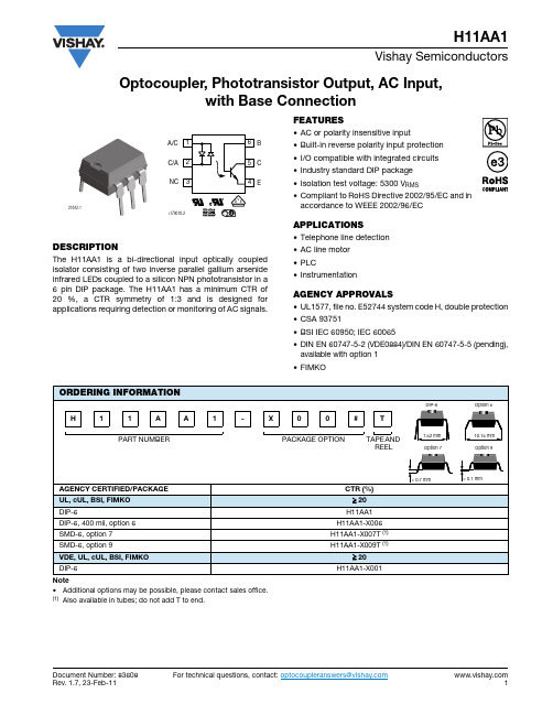
H11AA1 双向输入光纤隔离器说明书
Document Number: 83608For technical questions, contact: *****************************Optocoupler, Phototransistor Output, AC Input,with Base ConnectionH11AA1Vishay SemiconductorsDESCRIPTIONThe H11AA1 is a bi-directional input optically coupled isolator consisting of two inverse parallel gallium arsenide infrared LEDs coupled to a silicon NPN phototransistor in a 6 pin DIP package. The H11AA1 has a minimum CTR of 20 %, a CTR symmetry of 1:3 and is designed for applications requiring detection or monitoring of AC signals.FEATURES•AC or polarity insensitive input•Built-in reverse polarity input protection •I/O compatible with integrated circuits •Industry standard DIP package •Isolation test voltage: 5300 V RMS•Compliant to RoHS Directive 2002/95/EC and in accordance to WEEE 2002/96/ECAPPLICATIONS•Telephone line detection•AC line motor •PLC•InstrumentationAGENCY APPROVALS•UL1577, file no. E52744 system code H, double protection •CSA 93751•BSI IEC 60950; IEC 60065•DIN EN 60747-5-2 (VDE0884)/DIN EN 60747-5-5 (pending),available with option 1•FIMKONote•Additional options may be possible, please contact sales office.(1)Also available in tubes; do not add T to end.21842-1 For technical questions, contact: *****************************Document Number: 83608H11AA1Vishay Semiconductors Optocoupler, Phototransistor Output,AC Input, with Base ConnectionNote•Stresses in excess of the absolute maximum ratings can cause permanent damage to the device. Functional operation of the device is not implied at these or any other conditions in excess of those given in the operational sections of this document. Exposure to absolute maximum ratings for extended periods of the time can adversely affect reliability.Note•Minimum and maximum values were tested requierements. Typical values are characteristics of the device and are the result of engineering evaluations. Typical values are for information only and are not part of the testing requirements.ABSOLUTE MAXIMUM RATINGS (T amb = 25 °C, unless otherwise specified)PARAMETER TEST CONDITIONSYMBOLVALUEUNITINPUTForward continuous current I F ± 60mA Power dissipation P diss100mW Derate linearly from 25 °C 1.3mW/°COUTPUT Power dissipation P diss200mW Derate linearly from 25 °C2.6mW/°C Collector emitter breakdown voltage BV CEO 30V Emitter base breakdown voltage BV EBO 5V Collector base breakdown voltage BV CBO 70VCOUPLERIsolation test voltage (RMS)Between emitter and detector,referred to standard climate 23 °C/50% RH, DIN 50014V ISO5300V RMS Creepage distance ≥ 7mm Clearance distance ≥ 7mmComparative tracking index per DIN IEC 112/VDE 0303, part 1CTI 175Isolation resistance V IO = 500 V, T amb = 25°C R IO ≥ 1012ΩV IO = 500 V, T amb = 100°CR IO ≥ 1011ΩStorage temperature range T stg - 55 to + 150°C Operating temperature range T amb - 55 to + 100°C Lead soldering time at 260 °CT sld10s ELECTRICAL CHARACTERISTCS (T amb = 25 °C, unless otherwise specified)PARAMETER TEST CONDITIONSYMBOLMIN.TYP.MAX.UNITINPUTForward voltage I F = ± 10 mAV F1.21.5VOUTPUTCollector emitter breakdown voltage I C = 1 mA BV CEO 30V Emitter base breakdown voltage I E = 100 μA BV EBO 5V Collector base breakdown voltage I C = 100 μA BV CBO 70V Collector emitter leakage current V CE = 10 VI CEO5100nACOUPLERCollector emitter saturation voltageI F = ± 10 mA, I C = 0.5 mAV CEsat0.4VCURRENT TRANSFER RATIO (T amb = 25 °C, unless otherwise specified)PARAMETERTEST CONDITION SYMBOL MIN.TYP.MAX.UNIT DC current transfer ratioI F = ± 10 mA, V CE = 10 VCTR DC20%Symmetry(CTR at + 10 mA)/(CTR at - 10 mA)0.3313H11AA1Optocoupler, Phototransistor Output,AC Input, with Base ConnectionVishay Semiconductors TYPICAL CHARACTERISTICS (T amb = 25 °C, unless otherwise specified)Fig. 1 - LED Forward Current vs.Forward VoltageFig. 2 - Normalized Non-Saturated and Saturated CTR vs.LED CurrentFig. 3 - Normalized Non-Saturated and Saturated CTR vs.LED Current Fig. 4 - Normalized Non-Saturated and Saturated CTR vs.LED CurrentFig. 5 - Normalized Non-Saturated and Saturated CTR vs.LED CurrentFig. 6 - Collector Emitter Current vs.Temperature and LED CurrentDocument Number: 83608For technical questions, contact: *****************************H11AA1Vishay Semiconductors Optocoupler, Phototransistor Output,AC Input, with Base ConnectionFig. 7 - Collector Emitter Leakage Current vs. Temperature Fig. 8 - Normalized CTR cb vs. LED Current and Temperature Fig. 9 - Collector Base Photocurrent vs. LED Current Fig. 10 - Normalized Photocurrent vs. LED Current Fig. 11 - Normalized Saturated h FE vs.Base Current and TemperatureFig. 12 - Normalized Saturated h FE vs.Base Current and Temperature For technical questions, contact: *****************************Document Number: 83608Document Number: 83608For technical questions, contact: *****************************H11AA1Optocoupler, Phototransistor Output, AC Input, with Base ConnectionVishay Semiconductors Fig. 13 - Propagation Delay vs. Collector Load ResistorFig. 14 - Switching WaveformFig. 15 - Switching Schematic For technical questions, contact: *****************************Document Number: 83608H11AA1Vishay Semiconductors Optocoupler, Phototransistor Output,AC Input, with Base ConnectionPACKAGE DIMENSIONS in millimetersPACKAGE MARKINGNotes•Only options 1 and 7 are reflected in the package marking. •The VDE Logo is only marked on option1 parts.•Tape and reel suffix (T) is not part of the package marking.Legal Disclaimer Notice VishayDisclaimerALL PRODUCT, PRODUCT SPECIFICAT IONS AND DAT A ARE SUBJECT T O CHANGE WIT HOUT NOT ICE T O IMPROVE RELIABILITY, FUNCTION OR DESIGN OR OTHERWISE.Vishay Intertechnology, Inc., its affiliates, agents, and employees, and all persons acting on its or their behalf (collectively, “Vishay”), disclaim any and all liability for any errors, inaccuracies or incompleteness contained in any datasheet or in any other disclosure relating to any product.Vishay makes no warranty, representation or guarantee regarding the suitability of the products for any particular purpose or the continuing production of any product. To the maximum extent permitted by applicable law, Vishay disclaims (i) any and all liability arising out of the application or use of any product, (ii) any and all liability, including without limitation special, consequential or incidental damages, and (iii) any and all implied warranties, including warranties of fitness for particular purpose, non-infringement and merchantability.Statements regarding the suitability of products for certain types of applications are based on Vishay’s knowledge of typical requirements that are often placed on Vishay products in generic applications. Such statements are not binding statements about the suitability of products for a particular application. It is the customer’s responsibility to validate that a particular product with the properties described in the product specification is suitable for use in a particular application. Parameters provided in datasheets and / or specifications may vary in different applications and performance may vary over time. All operating parameters, including typical parameters, must be validated for each customer application by the customer’s technical experts. Product specifications do not expand or otherwise modify Vishay’s terms and conditions of purchase, including but not limited to the warranty expressed therein.Except as expressly indicated in writing, Vishay products are not designed for use in medical, life-saving, or life-sustaining applications or for any other application in which the failure of the Vishay product could result in personal injury or death. Customers using or selling Vishay products not expressly indicated for use in such applications do so at their own risk. Please contact authorized Vishay personnel to obtain written terms and conditions regarding products designed for such applications.No license, express or implied, by estoppel or otherwise, to any intellectual property rights is granted by this document or by any conduct of Vishay. Product names and markings noted herein may be trademarks of their respective owners.© 2017 VISHAY INTERTECHNOLOGY, INC. ALL RIGHTS RESERVEDRevision: 08-Feb-171Document Number: 91000。
PLC信号隔离器说明书
侧视图
标 准 精 度 : ±0 . 1 % / 25℃ 温 度 系 数 : ±0 . 0 1 5 %/℃
响 应 时 间 : ≤0.5s(0→90%)
电源电压变动的影响 : ≤0 . 1 % /允 许 电 压 范 围 绝 缘 电 阻 : 输入-输出-电源之间
1 0 0 MΩ 以 上/ D C 5 0 0 V
智能热电阻隔离器
机器规格
型号: X 35 R T
主要功能与特点
● 小型卡装式构造的信号隔离处理器 ● “ 输入-输出-电 源 ”三者 隔 离 ● 软件非线性修正,输入输出高线性度转换 ● 软件自稳零,消除温漂和时漂引起的误差 ● 用 户可通 过P C设定信号 范 围和信 号 类型 ● 可高密度安装
25
型号 X35V
代码
说明 智能电压隔离端子
输入信号 XX
10.0~5V 11.1~5V 12.0~10V
输出信号 供电电源 可选功能
1I/1V 2I/2V 3I/3V
AC DH DL
P
0~10mA/0~5V 4~20mA/1~5V 0~20mA/0~10V
85VAC~265VAC 18VDC~48VDC 12VDC~26VDC
智能热电偶隔离器
机器规格
型 号: X 3 5 T C
主要功能与特点
● 小型卡装式构造的信号隔离处理器 ● “ 输入-输出-电 源 ”三者 隔 离 ● 软件非线性修正,输入输出高线性度转换 ● 软件自稳零,消除温漂和时漂引起的误差 ● 用 户可通 过P C设定信号 范 围和信 号 类型 ● 可高密度安装
侧视图
标 准 精 度 : ±0 . 1 % / 25℃ 温 度 系 数 : ±0 . 0 1 5 %/℃
GST-8313A隔离器说明书

GST-LD-8313A隔离器安装使用说明书(Ver.1.03,2020.03)一、概述GST-LD-8313A隔离器(以下简称隔离器),主要用于隔离总线上发生短路的部分,保证总线上的其它设备正常工作。
待故障修复后,总线隔离器可将被隔离出去的部分重新纳入系统。
并且,使用隔离器便于确定总线发生短路的位置。
二、特点1.采用32位ARM微处理器实现信号处理,用数字信号与控制器进行通信,工作稳定可靠,对电磁干扰有良好的抑制能力;2.总线短路故障排除后,可将被隔离出去的部分重新纳入系统;3.输入、输出信号无极性;4.隔离器端口采用电压检测,产品性能更可靠;5.小型化设计,新型插拔式卡接结构,安装、拆卸简单方便,适合模块箱等多种安装方式。
三、技术特性1.工作电压:总线24V 允许范围:16V~28V2.工作电流:待机电流≤0.34mA 动作电流≤2.00mA;3.负载能力:每个隔离器后最多可配接32个设备;4.指示灯:动作指示灯,黄色,正常监视状态闪亮,线路故障时常亮;5.使用环境:温度:-10℃~+55℃相对湿度≤95%,不凝露6.外形尺寸:86mm×50mm×31mm ;7.外壳防护等级:IP30;8.壳体材料和颜色:ABS,白色;9.重量:约59g(带底壳);四、结构特征与工作原理1.隔离器的外形示意图如图1所示。
图1 外形示意图2.工作原理当隔离器检测到短路故障时,在短路部分上串入电阻;当隔离器检测到短路恢复后去掉电阻,并将被隔离部分重新纳入系统。
五、安装与布线警告:安装设备之前,请切断回路的电源并确认导轨已安装牢靠。
1.安装前应首先检查外壳是否完好无损,标识是否齐全。
2.模块端子及安装示意图如图2所示。
安装孔安装孔图2 端子及安装示意图接线说明如下:Z1、Z2:输入信号总线,无极性;ZO1、ZO2:输出信号总线,无极性。
3.布线要求:选用截面积不小于1.0mm2的RVS双绞线。
南京优倍隔离器说明书

通用型隔离器性能简介:输入电流/电压信号,变送输出隔离的电流/电压信号,实现了输入、输出与电源之间的三端隔离;本产品响应快,功耗低,温度特性好。
应用范围:可与各类仪表及DCS,PLC等设备配套使用,在石油、化工、制造、电力、冶金等行业的重大工程中有着广泛应用。
技术参数:隔离传输准确度:±0.1%F·S(25℃±2℃)输出纹波:<1mV响应时间:≤0.2ms;可订制更快响应时间的产品稳定时间:≤2ms信号频率范围:0Hz~300Hz(0Hz~5kHz可订制)温度漂移:<30ppm/℃输入阻抗:电流:≤60Ω;电压:0V~5V:≥1MΩ;0V~10V:≥2MΩ负载能力:0mA~10mA:≤600Ω;; 0(4)mA~20mA:≤300Ω-10mA~+10mA:≤1kΩ; -20mA~+20mA:≤500Ω0(1)V~5V:≥1MΩ;0V~10V:≥2MΩ-5V~+5V:≥1MΩ; -10V~+10V:≥2MΩ需要更大的负载能力请在订货时说明。
功耗:单路输出两路输出24VDC 0.4W0.6W220VAC1.0V A 1.2V A供电电压范围:18V DC~32V DC85V AC~265V AC(120V DC~360V DC)面板说明:PWR:电源指示灯(绿色);工作时常亮。
通用型隔离器选型型号说明NPGL-CM ╳╳╳╳╳通用型隔离器缺省为单通道输入通道D双通道1 4mA~20mA2 1V~5V3 0mA~10mA3E -10mA~10mA4 0V~5V4E -5V~5V5 0V~10V5E -10V~10V6 0mA~20mA输入信号6E -20mA~20mA14mA~20mA21V~5V30mA~10mA3E-10mA~10mA40V~5V4E-5V~5V50V~10V5E-10V~10V60mA~20mA第一路输出6E-20mA~20mA缺省为无第二路输出1 4mA~20mA21V~5V3 0mA~10mA3E -10mA~10mA40V~5V4E -5V~5V50V~10V5E -10V~10V6 0mA~20mA第二路输出6E -20mA~20mA缺省为交流220V供电方式D 直流24V选型说明:正负信号输出的产品仅支持一入一出。
PX-GL3.5音频隔离器说明书
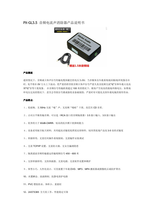
PX-GL3.5 音频电流声消除器产品说明书产品概述通常情况下,音频或立体声信号传输电缆屏蔽层的电压为0V,当多媒体及车载系统地回路/地环现象存在时,电平将在0V左右上下波动,更严重的将导致音频立体声信号严重失真及低频交流“嗡”音和车载火花高频“嗞”音等干扰现象。
在音频信号传输距离超过100米的情况下,极易产生较高的接地环路电压,如果地环电压过高的情况下,甚至会导致信号源或接收设备被烧毁,严重时有可能危及到车载电瓶的使用寿命。
产品特点:1、低底噪、无50Hz交流“嗡”声、无高频“嗞啦”干扰、高层次CD音质。
2、点对点平衡传输音频、可以选(RCA接口的音频隔离器)3.5接口输入、3.5接口输出3、优异的大于60dB-CMRR,较高的抗共模干扰抑制能力4、设备采用航空航天材料,具用超高灵敏度低照度还原特性,较同类低端产品高3-5倍的灵敏度5、即插即用,无需任何操作系统限制,无需输件安装调试6、无需TCP/IP设置,无需防火墙、无安全漏洞隐患7、隔离滤波音频传输最远传输视频信号450-600米8、支持即插即用,支持热插拨、无需电源,无需软件设置和维护9、体型小巧,人性化设计,可直接置于车载DVD、MP3、MP4播放器或摄像机后或防护罩内10、内置瞬态、浪涌抑制、抗静电保护电路11、PVC塑胶防水、体积小、重量轻12、24X7X365 全天侯工作,性能稳定可靠13、尺寸:长*宽*高(54*34*15) mm产品性能指标:输入输出隔离绝缘耐压:300Vp-p以上多媒体立体声隔离静噪器特性:设备插损<0.5dB回损:大于18dB接口: 3.5mm母头阻抗:300欧姆Min-600欧姆Max(输入-输出、输入电平:0.5Vp-p(Min)-1Vp-p - 3Vp-p (Max)、模拟地环路隔离及静噪处理音频响应带宽:50Hz-15KHz共模抑制:大于68dB@1KHz立体声通道隔离度:62dB工作温度:-10℃-85℃(车规级可选)储藏温度:-30℃-70℃适用音频格式:模拟立体声产品连接示意图:注:此产品不分输入输出,只需串接在音响线路中即可.。
信号隔离器说明书——苏州迅鹏

苏州迅鹏仪器仪表有限公司
XP 系列信号隔离器
概述
XP 系列信号隔离器 (一进一出,一进二出)是在自动化控制系统中对各种工业信号变送、转换、隔离、传输、运算的仪表,可 与各种工业传感器配合,取回参数信号,隔离变送传输,满足用户本地监视远程数据采集的需求。广泛应用于机械、电气、电信、 电力、石油、化工、钢铁、污水处理、楼宇建筑等领域的数据采集、信号传输转换、PLC、DCS 等工业测控系统,用来完善和补充 系统模拟∣/O 插件功能,增加系统适用性和现场环境的可靠度。
此系列信号隔离器还包含无源隔离器来自苏州迅鹏仪器仪表有限公司
w
7(/
.s
)$;
ur
po
n. c
om
95(L)*23(W) *120(H)mm
35mm 导轨卡装;主机与底座可以插拔分离
此系列信号隔离器还包含无源隔离器 特点
精度:≤±0.1%RO 测量:直流电压、直流电流等
隔离:输入、输出、电源三方完全隔离,抗干扰能力强 电源:DC24V 或 AC220V 支持带电热插拨装卸方便、精度高、线形度高、抗干扰性强、长期工作的稳定性
选型代码
w w
苏州迅鹏仪器仪表有限公司
w
7(/
.s
ur
)$;
po
n. c
om
XP系列信号隔离器
外形尺寸
接线图
w w
常用规格实例
Model:XP-A-A420-2A420-D (等同于 XP-A-A420-A420A420-D ,可以简写成 XP-A-A420-2A420-D) Input: 4~20mAdc Output1:4~20mAdc ; Output2:4~20mAdc Aux.power:DC24V 描述: 此产品为一进二出信号隔离器, 一路 4~20mA 直流信号输入 , 隔离变送输出两路信号, 输出1为 4~20mAdc 直流电流信号; 输出 2也为 4~20mA 直流电流信号;辅助电源为直流 24V.
GL 中文说明书

GL SERIESGL2400 中文说明书一年保修期购买者从购买此调音台即日开始,有一年期限的免费检测零件或者工艺的保修期。
为了保证高水准的演绎,请于操作前通读此用户指导手册。
在发生错误的情况下,如符合下列情形的保修条件,请将需要检修的产品注明并尽早返回到我司或者我们的代理机构检修。
保修条件1.用户是依据此用户指导手册的说明来安装与操作此调音台的。
2.除了如此用户手册或维修手册的描述,只要此调音台不是被滥用,有意,意外,疏忽,或者更改所引起的故障,或者是由我司认可的故障。
3.任何由我司或者代理机构所建议的调整,改装或修理。
4.此保修并不包括音量直滑推子的磨损。
5.需检修的产品要随同购买证明一起发送回我司或者代理机构,运费需预付。
6.返修的产品一定要打好包装以免运输故障发生。
在某些地方,这些条列可能会有改变。
如果有任何附加的保修,请与我司代理机构核对。
重要安全指示警告:在操作前请先阅读以下内容:阅读指示: 保留这些安全与操作指示以便日后使用。
包括所有印刷在这里与调音台上的警告。
根据此用户手册描述的操作指示来操作。
请勿拆除机箱: 操作时请保持机箱正常安装。
如果机箱需要拆除来设置内部选项,请先拨除电源线断开电源。
此工作只能由合格技术人员来执行。
电源来源: 只能按照此用户手册上所描述的与符合印在此调音台后面板上要求的电源,才可以连接到此调音台上。
电源线线路: 整理好电源线路,那样电源线才不会被踩,不会绊人或者被放置其上的物体压挤。
潮湿环境: 为了减少火患与电击的危险,请勿把此调音台暴露于雨水和湿气中,或者于潮湿或多雨的环境下使用此调音台。
请勿放置液体容器于调音台上,因其有可能会溅出并循空隙进入到调音台当中。
热量与振动: 请勿将调音台与可引起过热的设备放置在一起,或者直接放置于阳光底下,因为这样可引致火患发生。
把调音台远离哪些可产生热量或者过分振动的设备和地方。
维修: 如果暴露于潮湿环境中,有液体进入机内,有物体进入空隙内,电源线或者插头有损坏,暴风雨兼有打雷期间,或者察觉到机内冒烟,有气味或者产生噪音,请立刻关掉调音台,并拔掉电源线。
12路隔离语音控制器说明书
12路隔离语音控制器说明书V1.1(型号:YS-12)秦皇岛千目电子有限公司电话:************传真:************/1.产品特性 (2)2.产品图片、接口介绍 (2)2.1产品外形和接口图片 (2)2.2接口介绍 (3)2.3产品尺寸图 (3)3.语音录制过程 (3)3.1准备音频文件 (3)3.2硬件连接 (4)3.3录音下载 (4)3.3.1连接设备 (4)3.3.2录音 (4)3.3.3参数设置 (5)3.3.4放音测试 (5)4.控制方式 (5)4.1开关控制-12路开关 (5)4.1.1接线方式 (5)4.1.2控制方式 (6)4.2通讯协议 (6)5.技术支持及联系方式 (6)语音控制器说明书(型号:YS12)YS12语音控制器千目电子推出的一款新型语音产品。
具有价格低、稳定可靠、可重复录音等特点。
可广泛应用于工业控制、安防报警、语音提示等场合。
1.产品特性●12路光耦隔离输入控制信号,可以控制12路语音播放。
●485通讯支持Modbus-RTU协议,方便与其他设备进行组网调试。
●WA V音频格式,音频录制时间可达24分钟。
●板载FLASH存储器,成本低、可靠性更好。
●板载标准3.5MM音频孔,立体声输出,可外接音箱、音柱等功放设备。
●板载音频输出端子,可外接无源喇叭。
直接发声,方便应用。
●板载电源插孔,可直接插入电源。
●板载电源端子,方便工业现场接入电源。
●性能参数工作电源电压:直流12V1A工作温度:-20~85℃外接喇叭参数:8欧10W2.产品图片、接口介绍2.1产品外形和接口图片2.2接口介绍◆电源接口:支持电源插座和接线端子2种供电方式。
适应宽电压范围12V直流。
◆485通讯接口A+、B-:与485通讯设备功能1:进行模块参数设置。
(注:需要专门软件,我司免费提供)功能2:远程发送指令,控制语音模块播放语音。
◆音频2接口:声音输出接口,直接接无源喇叭,播放语音。
信号隔离器的使用方法
信号隔离器的使用方法1.引言1.1 概述信号隔离器是一种应用广泛的电子设备,用于处理电路中的信号传输和隔离问题。
它被广泛应用于工业自动化、电力系统、通信系统等领域,起到了至关重要的作用。
信号隔离器的主要作用是将电路中的信号进行隔离,防止信号传输时的干扰和噪音污染。
在很多情况下,不同电路之间的信号传递会导致互相影响和信号失真的问题。
这往往会导致电路的工作不稳定或者数据错误的传输。
而信号隔离器通过采用特定的电路设计和信号处理技术,能够有效地解决这些问题。
信号隔离器的工作原理基于电气隔离技术,它将输入信号电路和输出信号电路之间通过绝缘层进行隔离,使得两个电路之间的信号无法直接相互影响。
这种隔离方式能够有效降低噪音干扰、电磁干扰等因素对信号传输的影响,提高系统的稳定性和可靠性。
在信号隔离器的使用方法上,首先需要选择合适的信号隔离器类型和规格。
根据实际需求和电路特点,选择适合的隔离器能够更好地满足需求。
其次,在安装和连接时,需要按照隔离器的说明书进行正确的操作,并且保证信号输入端和输出端的连接正确可靠,避免接触不良等问题。
此外,使用信号隔离器时还需要注意电源供应和电气安全。
合理选择和配置电源,确保信号隔离器的正常工作和长期稳定性。
同时,在操作时要注意遵守电气安全规范,避免电路短路、过载等问题的发生。
总之,信号隔离器是一种重要的电子设备,其使用方法和原理对于保证电路信号传输和隔离的稳定性具有重要意义。
合理选择隔离器类型、正确安装和连接、注意电源供应和电气安全等方面的注意事项,能够保证信号隔离器的正常工作,并有效解决信号传输中的干扰和噪音问题。
希望本文能够帮助读者更好地理解信号隔离器的基本概念和使用方法,为相关领域的应用提供参考和指导。
1.2 文章结构文章结构部分:文章将从三个部分进行展开,即引言、正文和结论。
引言部分将首先概述信号隔离器的基本情况,介绍其用途和作用。
接着,探讨文章的结构,即本文将通过对信号隔离器的使用方法进行详细介绍,以使读者能够全面了解其使用要点。
通用型智能隔离器说明书
16 + (L)
单路电流输入-单输出
-1
V
+2
9+
输出
10 -
14 接地
15 -(N)
电源
16 + (L)
单路电压输入-单输出
-1
mA
+2
9+
10
输出1
-
-1
电压输入
11 +
+2
12
输出2
-
14 接地
15 - (N)
16
电源
+ (L)
9+
10
输出1
-
11 +
12
输出2
-
14 接地
15 -(N)
16
ANPE 优倍电气 America New Power Electric
NPGL 通用型智能隔离器使用说明书
变送仪表专家
☞ 先进技术
√ 全智能、数字化、可编程; √ 环境温度、零点、满幅自动补偿; √ 极高的稳定性,确保准确度多年不变; √ 电源、输入、输出、双回路间高隔离度; √ 符合国际电工委员会 IEC61000 相关抗电磁干扰标准。
☞ 选型说明
□ 单回路输入最多可以有两路输出,双回路输入每路只能对应 一路输出。
□ 双回路产品输入信号如需不同,请与本公司联系特殊订货; □ 含通讯产品仅单输入,并且最多只有一路输出。
ANPE 优倍电气 America New Power Electric
变送仪表专家
☞ 面板指示
□ PWR:电源指示灯(绿色); □ ALM:输入信号报警指示灯(红色);
☞ 使用环境
安装位置不得有强烈振动,以及来自信号端、电源端及空间 的超过 IEC61000-4-4:1995 中第三类工业现场电磁干扰的强度, 并使用环境中不得有对金属、塑料件起严重腐蚀作用的有害物质。
Radial Twin-Iso双通道线级隔离器说明书

Radial Engineering Ltd.1845 Kingsway Ave., Port Coquitlam, BC V3C 1S9, Canada Tel: 604-942-1001 • Fax: 604-942-1010 email:******************Twin-Iso ™True to the Music Radial Twin-Iso user guide - Part #: R870 1025 00 / 10-2021User Guide ®WELCOMECongratulations on your purchase of the Radial Twin-Iso stereo (dual mono) line-level isolator. The Twin-Iso is a handy device that will allow you to isolate audio equipment and eliminate troublesome noise caused by ground loops.The Radial Twin-Iso employs two high-performance Jensen isolation transformers to ensure the best signal transfer is enjoyed without artifacts or distortion. This makes the Twin-Iso a perfect choice where multiple consoles need to be sub-mixed, when isolating amplifi er distribution racks and for connecting remote speaker towers. The Twin-Iso can also eliminate ground loop problems where equipment must be connected to alternate power sources such as generators.As with all Radial products, the Twin-Iso is made with 14 gauge steel and features an internal welded I-beam frame for maximum rigidity. Switches and jacks are protected by our unique bookend construction, making the Twin-Iso virtually impossible to damage even in the most abusive touring environments.We have purposely written this manual to be short, as most users will likely be familiar with the Twin-Iso’s applications. We do suggest that you take a moment to read through this document to familiarize yourself with the features that have been built in. For more detailed information, please visit the Radial website. This is where we post questions and answers that come from users after the product is released. If you do not fi nd an answer, we invite you to send *********************************************************** query in a prompt and professional manner.The Radial Twin-Iso is a wonderful device that will surely provide you with years of problem-solving connectivity. Enjoy!INTRODUCTIONThe Radial Twin-Iso has been designed to provide electrical isolation between two line-level devices such as between two mixing consoles, remote speakers, crossovers and amplifi er racks. Use the Twin-Iso anywhere source and destination devices may cause system noise because of diff erent ground potentials (often referred to as ground loops).So-called ground loops are caused by diff ering voltage references from various pieces of equipment that, when connected together, can introduce a 60 cycle hum in the sound system. Although there are various solutions that can beengineered to eliminate noise, the simplest and most eff ective is to isolate the source and destination with an audio transformer.The Radial Twin-Iso employs two high-quality Jensen transformers to do the task. Jensen is renowned for their quality and the ability of their transformers to handle high signal levels without saturation and transfer the signal without introducing phase distortion or group delay. Although the cost is higher, a good quality transformer will assure the signal remains true to the source, resulting in better sound.When you fi rst pick up the Radial Twin-Iso, you will immediately notice the weight. This ‘hefty’ device employs a welded steel I-beam internal construction to assure the internal PCB will not torque, preventing part failure. Besides the heavy-duty enclosure, the extra-large transformers add to the Twin-Iso’srobustness. As a rule, the larger the transformer, the more signal handling capacity it will have and Jensen transformers can drive loads of 600 ohms up to +21dBu at 20Hz.The Radial Twin-Iso is equipped with two XLR inputs and two XLR outputs. Each channel is 100% isolated from the other to eliminate cross-talk or interaction, thus allowing two completely diff erent audio sources to use the Twin-Iso at the same time. Although the Twin-Iso is designed for +4dB professional line-level signals, the transformers will actually handle over 20dB without choking.Each of the Twin-Iso’s outputs feature a 180° polarity reverse switch to ensure both consoles are ‘in phase’ and pushing the speakers in the same direction. This allows the Twin-Iso to feed a sub-group or auxiliary input of a console where polarity reversals are generally not provided. Finally, the Twin-Iso is equipped with a ground lift switch to further reduce system noise should it be present.USING THE TWIN-ISOAs with all Radial products, using the Twin-Iso is simple and straight forward. Make sure the sound system is turned off and all levels are set to zero before making audio connections. This will avoid any pops in the sound system that could cause damage to speakers.The Twin-Iso is completely passive and does not require a power supply of any kind. Connect the source device to the Twin-Iso inputs. Connect the Twin-Iso outputs to the destination device. Turn the system up slowly and listen for noise. In the unlikely event you should encounter noise, simply depress the ground lift switch. That’s all there is to it.AUX CONSOLE master outputs connect to Twin-Iso inputs.MAIN CONSOLE Twin-Iso outputs feed main console.J-RAK The optional J-RAK™ is a high density rackshelf for Radial DI’s and splitters.It’s a 2RU rack chassis that allows up to 8 Radial devices in one neat high density 19" package. The DI’s can be mounted with either the input side or output side facing the front. Ideal for studio or touring. Constructed of 14 gauge steel with a baked enamel fi nish.J-CLAMP The optional J-CLAMP™ can mount a single Radialdevice to virtually any surface. Perfect for hiding awayinside racks, on podiums or under tables. Constructedof 14-gauge steel with a baked enamel fi nish.TWIN-ISO BLOCK DIAGRAM LEFT IN LEFT OUT RIGHT IN RIGHT OUT POLARITY GND LIFTPOLARITY98INPUT PANEL1. Ground lift (inputs) Lifts the ground pin-1 on bothXLR input connectors. 2. Input-1 & 2 For low impedance, balanced line-level signals.3. Bookend design 14gauge steel outer shellcreates protective zone around connectors andswitches. OUTPUT PANEL4. Output-1 & 2 line-level transformer-isolatedoutputs.5. Polarity reverse 180°- Polarity reverse switch foroutputs-1 & 2.6. Full-bottom no-slip pad This provides electricalisolation and plenty of"stay-put" friction to keepthe Twin-ISO in one place.CONSTRUCTION7. Ultra rigid steel I-beam enclosure eliminatesstress that could torquethe PC board and causesolder joint failure.8. Jensen transformers off er outstanding audioperformance.9. Military-grade double-sided PCB with plated through-holes is bolted towelded steel standoff s.10. Sturdy high-cycle PCB mounted switches arerated for long life.731056TWIN-ISO SPECIFICATIONSFrequency response 10Hz to 50kHz +/- 1dBMax output level +21dBu (20Hz, 1% THD)Phase distortion 0.3° at 20HzTotal harmonic distortion 0.001% THD @1k, +4dBu (0.035% at 20Hz) Common-mode rejection 94dB @ 60Hz (83dB @ 3kHz)Inputs Balanced, line-level, pin-2 hotOutputs Balanced, line-level, pin-2 hotPower requirement None, completely passiveSize 3.25" x 5" x 1.875"Weight2 lbs.RADIAL LIMITED THREE YEARTRANSFERABLE WARRANTYRADIAL ENGINEERING LTD. (“Radial”) warrants this product to be free from defects in material and workmanship and will remedy any such defects freeof charge according to the terms of this warranty. Radial will repair or replace (at its option) any defective component(s) of this product (excluding fi nish and wear and tear on components under normal use) for a period of three (3) years from the original date of purchase. In the event that a particular product is no longer available, Radial reserves the right to replace the product with a similar product of equal or greater value. To make a request or claim under this limited warranty, the product must be returned prepaid in the original shipping container (or equivalent) to Radial or to an authorized Radial repair center and you must assume the risk of loss or damage. A copy of the original invoice showing dateof purchase and the dealer name must accompany any request for work to be performed under this limited and transferable warranty. This limited warranty shall not apply if the product has been damaged due to abuse, misuse,misapplication, accident or as a result of service or modifi cation by any other than an authorized Radial repair center.THERE ARE NO EXPRESSED WARRANTIES OTHER THAN THOSE ON THE FACE HEREOF AND DESCRIBED ABOVE. NO WARRANTIES WHETHER EXPRESSED OR IMPLIED, INCLUDING BUT NOT LIMITED TO, ANY IMPLIED WARRANTIES OF MERCHANTABILITY OR FITNESS FOR A PARTICULAR PURPOSE SHALL EXTEND BEYOND THE RESPECTIVE WARRANTY PERIOD DESCRIBED ABOVE OF THREE YEARS. RADIAL SHALL NOT BE RESPONSIBLE OR LIABLE FOR ANY SPECIAL, INCIDENTAL OR CONSEQUENTIAL DAMAGES OR LOSS ARISING FROM THE USE OF THIS PRODUCT. THIS WARRANTY GIVES YOU SPECIFIC LEGAL RIGHTS, AND YOU MAY ALSO HAVE OTHER RIGHTS, WHICH MAY VARY DEPENDING ON WHERE YOU LIVE AND WHERE THE PRODUCT WAS PURCHASED.True to the Music ®。
- 1、下载文档前请自行甄别文档内容的完整性,平台不提供额外的编辑、内容补充、找答案等附加服务。
- 2、"仅部分预览"的文档,不可在线预览部分如存在完整性等问题,可反馈申请退款(可完整预览的文档不适用该条件!)。
- 3、如文档侵犯您的权益,请联系客服反馈,我们会尽快为您处理(人工客服工作时间:9:00-18:30)。
PX-GL001A 单声道音频电流声消除器产品说明书
产品概述
通常情况下,音频或立体声信号传输电缆屏蔽层的电压为0V,当多媒体及车载系统地回路/地环现象存在时,电平将在0V左右上下波动,更严重的将导致音频立体声信号严重失真及低频交流“嗡”音和车载火花高频“嗞”音等干扰现象。
在音频信号传输距离超过100米的情况下,极易产生较高的接地环路电压,如果地环电压过高的情况下,甚至会导致信号源或接收设备被烧毁,严重时有可能危及到车载电瓶的使用寿命。
产品特点:
1、低底噪、无50Hz交流“嗡”声、无高频“嗞啦”干扰、高层次CD音质。
2、单路高保真(RCA接口的音频隔离器)RCA接口输入、输出。
3、优异的大于60dB-CMRR,较高的抗共模干扰抑制能力
4、设备采用航空航天材料,具用超高灵敏度低照度还原特性,较同类低端产品高3-5倍的灵敏度
5、即插即用,无需任何操作系统限制,无需输件安装调试
6、无需TCP/IP设置,无需防火墙、无安全漏洞隐患
7、隔离滤波音频传输最远传输视频信号450-600米
8、支持即插即用,支持热插拨、无需电源,无需软件设置和维护
9、体型小巧,人性化设计,可直接置于车载DVD、MP3、MP4播放器或摄像机后或防护罩内
10、内置瞬态、浪涌抑制、抗静电保护电路
11、PVC塑胶防水、体积小、重量轻
12、24X7X365 全天侯工作,性能稳定可靠
13、尺寸:长*宽*高58mm*31mm*21mm
产品性能指标:
输入输出隔离绝缘耐压:500Vp-p以上
多媒体立体声隔离静噪器特性:设备插损<0.5dB回损:大于18dB
接口:RCA母头
阻抗:300欧姆Min-600欧姆Max(输入-输出、输入电平:0.5Vp-p(Min)-1Vp-p - 3Vp-p (Max)、模拟地环路隔离及静噪处理
音频响应带宽:20Hz-15KHz
共模抑制:大于68dB@1KHz
立体声通道隔离度:62dB
工作温度:-10℃-85℃(车规级可选)
储藏温度:-30℃-70℃
适用音频格式:模拟立体声
产品连接示意图:
注:此产品不分输入输出,只需串接在音响线路中即可.。
