XM35T信号隔离器说明书
隔离器说明书

m XP 系列信号隔离器 co 概述 . XP 系列信号隔离器(一进一出,一进二出)是在自动化控制系统中对各种工业信号变送、转换、隔离、传输、运算的仪表,可 n 与各种工业传感器配合,取回参数信号,隔离变送传输,满足用户本地监视远程数据采集的需求。广泛应用于机械、电气、电信、 o 电力、石油、化工、钢铁、污水处理、楼宇建筑等领域的数据采集、信号传输转换、PLC、DCS 等工业测控系统,用来完善和补充 p 系统模拟∣/O 插件功能,增加系统适用性和现场环境的可靠度。 ur 特点 s 测量:直流电压、直流电流等 . 精度:≤±0.1%RO w 隔离:输入、输出、电源三方完全隔离,抗干扰能力强 w 电源:DC24V 或 AC220V w 支持带电热插拨装卸方便、精度高、线形度高、抗干扰性强、长期工作的稳定性
7(/
)$;
Model:XP-V-V010-A420-D Input: 0~10Vdc Output1:4~20mAdc Aux.power:DC24V 描述:此产品为一进一出信号隔离器,一路 0~10Vdc 直流电压信号输入,隔离变送输出一路 4~20mAdc 直流电 流信号;辅助电源为直流 24V.
苏州迅鹏仪器仪表有限公司
选型代码
苏州迅鹏仪器仪表有限公司
7(/
)$;
外形尺寸
95(L)*23(W) *120(H)mm
XP系列信号隔离器
35mm 导轨卡装;主机与底座可以插拔分离
接线图
www.surpon.com
常用规格实例
Model:XP-A-A420-2A420-D(等同于 XP-A-A420-A420A420-D,可以简写成 XP-A-A420-2A420-D) Input: 4~20mAdc Output1:4~20mAdc ; Output2:4~20mAdc Aux.power:DC24V 描述:此产品为一进二出信号隔离器,一路 4~20mA 直流信号输入,隔离变送输出两路信号,输出 1 为 4~20mAdc 直流电流信号;输出 2 也为 4~20mA 直流电流信号;辅助电源为直流 24V.
信号隔离器及功能及工作原理

信号隔离器及功能及工作原理信号隔离器的功能及工作原理信号隔离器的工作原理及功能是什么?工作原理:首先将变送器或仪表的信号,通过半导体器件调制变换,然后通过光感或磁感器件进行隔离转换,然后再进行解调变换回隔离前原信号,同时对隔离后信号的供电电源进行隔离处理。
保证变换后的信号、电源、地之间绝对独立。
功能:一:保护下级的控制回路。
二:消弱环境噪声对测试电路的影响。
三:抑制公共接地、变频器、电磁阀及不明脉冲对设备的干扰;同时对下级设备具有限压、额流的功能是变送器、仪表、变频器、电磁阀PLC/DCS输入输出及通讯接口的忠实防护。
DIN系列导轨结构,易于安装,可有效的隔离:输入、输出和电源及大地之间的电位。
能够克服变频器噪声及各种高低频脉动干扰。
信号隔离器的主要类型有哪些?隔离器:工业生产中为增加仪表负载能力并保证连接同一信号的仪表之间互不干扰,提高电气安全性能。
需要将输入的电压、电流或频率、电阻等信号进行采集、放大、运算、和进行抗干扰处理后,再输出隔离的电流和电压信号,安全的送给二次仪表或plc\dcs使用。
配电器:工业现场一般需要采用两线制传输方式,既要为变送器等一次仪表提供24V配电电源,同时又要对输入的电流信号进行采集、放大、运算、和进行抗干扰处理后,再输出隔离的电流和电压信号,供后面的二次仪表或其它仪表使用。
安全栅:一些特殊的工业现场(如燃气公司和化工厂)不但需要两线制传输,既提供配电电源又有信号隔离功能,同时还需要具有安全火花防爆的性能,可靠地遏制电源功率、防止电源、信号及地之间的点火,限流、降压双重限制信号及电源回路,把进入危险场所的能量限制在安全定额范围内。
信号隔离器安装维护应注意哪些事项?由于生产厂家不同,对隔离器的生产工艺、接线定义也不都相同,但使用场合基本相同,所以对产品的防护要求及维护基本相同。
1.使用前应详细阅读说明书。
2.作为信号隔离使用时,应将输入端串入环路电路中,输出端接取样回路。
信号隔离器的作用和使用注意事项

信号隔离器的作用和使用注意事项信号隔离器在工业生产过程中实现监视和控制需要用到各种自动化仪表、控制系统和执行机构,它们之间的信号传输既有微弱到毫伏级、微安级的小信号,又有几十伏,甚至数千伏、数百安培的大信号;既有低频直流信号,也有高频脉冲信号等等,构成系统后往往发现在仪表和设备之间信号传输互相干扰,造成系统不稳定甚至误操作。
出现这种情况除了每个仪表、设备本身的性能原因如抗电磁干扰影响外,还有一个十分重要的因素就是由于仪表和设备之间的信号参考点之间存在电势差,因而形成“接地环路”造成信号传输过程中失真。
因此,要保证系统稳定和可靠的运行,“接地环路”问题是在系统信号处理过程中必须解决的问题。
解决“接地环路”的方法根据理论和实践分析,有三种解决方案:第一种方案:所有现场设备不接地,使所有过程环路只有一个接地点,不能形成回路,这种方法看似简单,但在实际应用中往往很难实现,因为某些设备要求必须接地才能保证测量精度或确保人生安全,某些设备可能因为长期遭到腐蚀和磨损后或气候影响而形成新的接地点。
第二种方案:使两接地点的电势相同,但由于接地点的电阻受地质条件及气候变化等众多因素的影响,这种方案其实在实际中无法完全能做到。
第三种方案:在各个过程环路中使用信号隔离方法,断开过程环路,同时又不影响过程信号的正常传输,从而彻底解决接地环路问题。
作为一种连接现场仪表和控制室设备的电子接口模块,信号隔离器通常安装在控制室机柜的导轨上,新手朋友对信号隔离器的使用,还有些陌生,对有哪些注意事项尚不十分了解,下面说说信号隔离器的使用注意事项有哪些呢?第一:信号隔离器使用前根据装箱单,以及产品标签,仔细核对和确认产品数量、型号和规格,并认真阅读信号隔离器的使用说明书;第二:信号隔离器的使用环境应无导电粉尘,无腐蚀性气体、无强烈冲击和振动。
第三:信号隔离器为一体化结构,不可拆卸,同时应避免碰撞和跌落,请勿涂改和撕下产品上的任何标贴。
Everlight IRM-36xxM3F45系列微型红外接收器说明书
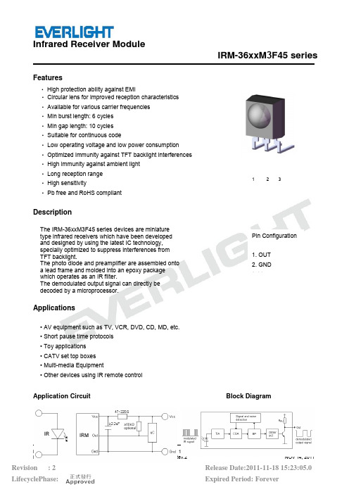
IRM-36xxM 3F45 seriesFeatures‧High protection ability against EMI‧Circular lens for improved reception characteristics ‧Available for various carrier frequencies ‧Min burst length: 6 cycles ‧Min gap length: 10 cycles ‧Suitable for continuous code‧Low operating voltage and low power consumption Optimized immunity against TFT backlight ‧interferences ‧High immunity against ambient light ‧Long reception range ‧High sensitivity‧Pb free and RoHS compliantDescriptionThe IRM-36xxM 3F45 series devices are miniature type infrared receivers which have been developed and designed by using the latest IC technology, specially optimized to suppress interferences from TFT backlight.The photo diode and preamplifier are assembled onto a lead frame and molded into an epoxy package which operates as an IR filter.The demodulated output signal can directly be decoded by a microprocessor.Applications• AV equipment such as TV, VCR, DVD, CD, MD, etc.• Short pause time protocols • Toy applications • CATV set top boxes • Multi-media Equipment• Other devices using IR remote controlApplication Circuit Block DiagramPin Configuration 1.OUT 2.GND 3.V123IRM-36xxM3F45 seriesThe RC Filter must be connected as close as possible toVcc and GND pins.Parts TableModel No.Carrier FrequencyIRM-3636M3F4536 kHzIRM-3638M3F4538 kHzIRM-3640M3F4540 kHzPackage Dimensions(Dimensions in mm)IRM-36xxM3F45 seriesNotes:Tolerances unless dimensions ±0.3mm.Absolute Maximum Ratings (T a=25°C)Parameter Symbol Rating UnitSupply Voltage Vcc6VOperating Temperature Topr-20 ~ +80Storage Temperature Tstg-40 ~ +85IRM-36xxM3F45 seriesSoldering Temperature *1Tsol260*1 4mm from mold body for less than 10 secondsElectro-Optical Characteristics (Ta=25 , Vcc=3V)Parameter Symbol MIN.TYP.MAX.Unit ConditionCurrent consumption Icc---0.40.6mA No input signal Supply voltage V CC 2.7- 5.5VPeak wavelengthλp---940---nmReception range L014------mSee chapter‚Test method’L456------Half angle(horizontal)φh---±35---degHalf angle(vertical)φv---±35---degHigh level pulse width T H450---700μs Test signalaccording tofigure 1Low level pulse width T L500---750μsHigh level output voltage V OH Vcc-0.4------V I SOURCE 1μA Low level output voltage V OL---0.20.5V I SINK 2mA Internal pull up resistor R PU85100115kΩTest methodThe specified electro-optical characteristics are valid under the following conditions.1.Measurement environmentA place without extreme light reflections.2.External lightThe environment contains an ordinary, white fluorescent lamp without high frequency modulation. The color temperature is 2856K and the illumination at the IR receiver is less than 10 Lux (Ev 10Lux).3.Standard transmitterThe test transmitter is calibrated by transmitter is adjusted until Vo=400wavelength of 940nm. The photo dio 4.The measurement system is shown Fig.-1 Transmitter Wave F Fig.-2 standard transmitte TypicalElectro-Optical Charac d by using the circuit shown in figure 2. The radiation =400mVp-p. Both,the test transmitter and the photo d oto diode for calibration is PD438B (λp=940nm,Vr=5V hown in Fig.-3ave FormD.U.T out mitter calibration Fig.-3 Mea haracteristicCurvesIRM-36xxM 3F45 seriesation intensity of the hoto diode,have a peak r=5V).T output PulseMeasuring SystemIRM-36xxM3F45 seriesIRM-36xxM3F45 series Code informationProtocol Suitable Protocol SuitableJVC Yes RCA YesMatsushita Yes Sharp YesMitsubishi Yes Sony 12 Bit YesNEC Yes Sony 15 Bit NoRC5Yes Sony 20Bit NoRC6Yes Toshiba YesRCMM Yes Zenith YesRCS-80Yes Continuous Code YesDevice MarkingNotes1 denotes Year code2 denotes Month code3 denotes Device number4denotes Carrier frequency(2: 36KHz, 4: 38KHz and 5: 40KHz)Packing Quantity1500 pcs / Box10 Boxes / CartonIRM-36xxM3F45 series DISCLAIMER1.Above specification may be changed without notice. EVERLIGHT will reserve authority on materialchange for above specification.2.When using this product, please observe the absolute maximum ratings and the instructions for useoutlined in these specification sheets. EVERLIGHT assumes no responsibility for any damage resulting from use of the product which does not comply with the absolute maximum ratings and the instructions included in these specification sheets.3.These specification sheets include materials protected under copyright of EVERLIGHT. Reproduction inany form is prohibited without the specific consent of EVERLIGHT.。
苏州迅鹏信号隔离器英文说明书(最全)word资料
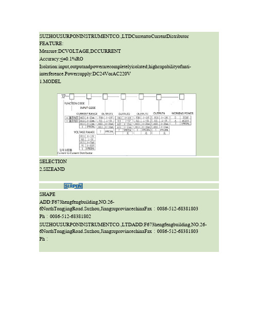
SUZHOUSURPONINSTRUMENTCO.,LTDCurrenttoCurrentDistributor FEATURE:Measure:DCVOLTAGE,DCCURRENTAccuracy:≤±0.1%ROIsolation:input,outputandpowerarecompletelyisolated;highcapabilityofanti-interference.Powersupply:DC24VorAC220V1.MODELSELECTION2.SIZEANDSHAPEADD:F673hengfengbuilding,NO.26-6NorthTongjingRoad.Suzhou,JiangsuprovincechinaFax:0086-512-68381803 Ph:0086-512-68381802SUZHOUSURPONINSTRUMENTCO.,LTDADD:F673hengfengbuilding,NO.26-6NorthTongjingRoad.Suzhou,JiangsuprovincechinaFax:0086-512-68381803 Ph:0086-512-68381802SUZHOUSURPONINSTRUMENTCO.,LTDADD:F673hengfengbuilding,NO.26-6NorthTongjingRoad.Suzhou,JiangsuprovincechinaFax:0086-512-68381803 Ph:0086-512-68381802模拟量信号隔离模块、模拟量信号隔离器产品型号:DATA-8301产品概述:模拟量信号隔离模块主要用于对各类4~20mA信号采集设备或控制设备进行隔离保护。
该隔离模块实现了电源、输入信号、输出信号的全面隔离,唐山平升模拟量信号隔离模块可有效消除串流、电磁、谐波等干扰信号、显著提高信号质量。
交流信号隔离器的参数和特点

交流信号隔离器的参数和特点交流信号隔离器是一种常用的电子元器件,可以有效地隔离交流信号,提高信号传输质量。
本文将介绍交流信号隔离器的参数和特点。
一、参数交流信号隔离器的参数主要包括插入损耗、隔离度、通频带、输入/输出电阻、工作电压等。
1. 插入损耗插入损耗是指信号通过隔离器时,隔离器内部产生的信号损耗,一般以dB为单位表示。
插入损耗越小,表示信号损失越小,隔离效果越好。
2. 隔离度隔离度是指隔离器对输入信号与输出信号之间的隔离程度,一般以dB为单位表示。
隔离度越高,表示隔离器隔离能力越强,对信号的隔离效果越好。
3. 通频带通频带是指隔离器在隔离信号时,对信号的频率范围。
一般来说,隔离器的通频带越宽,可以隔离的频率范围就越广。
4. 输入/输出电阻输入/输出电阻是指隔离器在输入/输出端口的电阻值。
一般来说,输入/输出电阻越小,对信号的干扰就越小。
5. 工作电压工作电压是指隔离器能够正常工作的最大电压值。
在使用隔离器时,应该根据隔离器的工作电压范围来选择合适的电源。
二、特点交流信号隔离器具有如下的特点:1. 隔离效果好交流信号隔离器能够有效地隔离输入信号和输出信号,降低信号干扰、提高信号传输效率。
2. 通用性强交流信号隔离器适用于多种场景,如电力系统、工控系统、通讯系统、仪器仪表等,具有很强的通用性。
3. 安装简便交流信号隔离器通常具有小体积、轻便的特点,安装也十分简便。
4. 维护成本低交流信号隔离器的维护成本低,可以长时间稳定工作,不需要定期更换零部件,降低了使用成本。
三、总结交流信号隔离器是一种十分实用的电子元器件,能够有效地提高信号传输质量,具有插入损耗小、隔离效果好、通用性强、安装简便、维护成本低等特点。
在实际应用中,应该根据需要选择合适的隔离器,提升信号传输效率,保障系统的稳定运行。
单通道智能型隔离器使用说明书
使用说明书U-YAP602S-LCCN1 1性能简介输入电流或电压信号,经过变换,输出隔离的电流或电压信号,实现了输入、输出与电源之间的三端隔离,可以给现场的变送器提供隔离的工作电源。
本产品响应快,功耗低,温度特性好。
可与各类仪表及DCS,PLC等设备配套使用,在石油、石化、制造、电力、冶金等行业的重大工程中有着广泛应用。
2技术参数输入信号(1,2,3):电流:0(4)mA~20mA;0mA~10mA电压:0(1)V~5V;0V~10V如需其它信号类型请订制,具体信号类型详见产品标签输入阻抗:电流:≤60Ω电压:≥1MΩ输出信号(7,8,9;10,11,12):无源电流:4mA~20mA有源电流:0(4)mA~20mA;0mA~10mA直流电压:0(1)V~5V;0V~10V如需其它信号类型请订制,具体信号类型详见产品标签输出纹波:≤5mV rms(负载250Ω)负载能力:无源电流:RL≤[(U-3)/0.02]Ω;U为回路供电电压0(4)mA~20mA:≤550Ω;0mA~10mA: ≤1.1kΩ0(1)V~5V:≥1MΩ; 0V~10V:≥2MΩ配电电压:空载电压≤26V,满载电压≥22V隔离传输准确度:±0.1%F.S(25℃±2℃)温度漂移:40ppm/℃响应时间:≤0.5s介电强度(漏电流1mA,测试时间1分钟):≥1500V AC(输入/输出/电源之间)电磁兼容:EMC符合IEC 61326-3-1满载功耗:220V AC供电,空载功耗≤0.8W220V AC供电,满载功耗≤2.5W供电电压范围:85V AC~265V AC(90V DC~360V DC)3输出状态跟随方式:在用户不特别指明的情况下,无论输入信号出现何种故障状态(4~20mA或1~5V 输入断线或短路除外,此时输出0mA/ V),在满量程范围内输出均跟随输入信号变化,但最大不超出输出量程上限的110% (如0~20mA输出时,最小输出可为0mA,最大不超过22mA)。
深圳万讯隔离器说明书
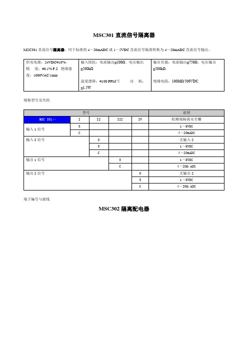
MSC301直流信号隔离器MSC301直流信号隔离器,用于标准的4~20mADC或1~5VDC直流信号隔离转换为4~20mADC直流信号输出。
规格型号及代码端子编号与接线MSC302隔离配电器MSC302隔离配电器向现场二线制变送器提供工作电源,同时将现场二线制变送器的电流信号转化为4~20mADC或1~5VDC直流信号输出。
规格型号及代码端子编号与接线MSC304热电阻温度变送器MSC304热电阻温度变送器,将现场热电阻的电势信号隔离转换为一路或二路与温度范围相对应的直流信号输出。
且每一路输入/电源/输出完全隔离。
规格型号及代码端子编号与接线MSC303热电偶温度变送器MSC303热电偶温度变送器,将现场热电偶的电势信号隔离转换为温度范围相对应的直流信号输出。
主要技术指标供电电源:24VDC±10%;精度:±0.1% F.S(Δ>10mV)±0.2% F.S(10mV>Δ>5Mv)输出负载:电流输出≤750Ω、电压输出≥500kΩ温度漂移:±150 PPM/℃绝缘电阻:100MΩ/500VDC绝缘强度:1000V/1min 功耗:≤1.5W型号说明 MSC303-I II III IV 热电偶温度变送器输入1信号1 K型热电偶2 S型热电偶3 E型热电偶4 B型热电偶5 R型热电偶6 T型热电偶7 J型热电偶G 其他热电偶输入2信号0 无输入2输出1信号2 0~5VDC3 1~5VDCB 0~20mA DCC 4~20mA DC G 其他量程输出2信号0 无输出22 0~5VDC3 1~5VDCB 0~20mA DCC 4~20mA DC G 其他量程端子编号与接线MSC305滑线电阻变送器MSC305型滑线电阻变送器,将滑线电阻滑动臂的电阻变化信号隔离转换为与其阻值对应的4~20mADC或1~5VDC直流信号输出。
供电电源:24VDC±10% 激励电流:≤0.3Ma精度:±0.1% F.S线性:输出于被测电阻呈线性关系。
PLC信号隔离器说明书
侧视图
标 准 精 度 : ±0 . 1 % / 25℃ 温 度 系 数 : ±0 . 0 1 5 %/℃
响 应 时 间 : ≤0.5s(0→90%)
电源电压变动的影响 : ≤0 . 1 % /允 许 电 压 范 围 绝 缘 电 阻 : 输入-输出-电源之间
1 0 0 MΩ 以 上/ D C 5 0 0 V
智能热电阻隔离器
机器规格
型号: X 35 R T
主要功能与特点
● 小型卡装式构造的信号隔离处理器 ● “ 输入-输出-电 源 ”三者 隔 离 ● 软件非线性修正,输入输出高线性度转换 ● 软件自稳零,消除温漂和时漂引起的误差 ● 用 户可通 过P C设定信号 范 围和信 号 类型 ● 可高密度安装
25
型号 X35V
代码
说明 智能电压隔离端子
输入信号 XX
10.0~5V 11.1~5V 12.0~10V
输出信号 供电电源 可选功能
1I/1V 2I/2V 3I/3V
AC DH DL
P
0~10mA/0~5V 4~20mA/1~5V 0~20mA/0~10V
85VAC~265VAC 18VDC~48VDC 12VDC~26VDC
智能热电偶隔离器
机器规格
型 号: X 3 5 T C
主要功能与特点
● 小型卡装式构造的信号隔离处理器 ● “ 输入-输出-电 源 ”三者 隔 离 ● 软件非线性修正,输入输出高线性度转换 ● 软件自稳零,消除温漂和时漂引起的误差 ● 用 户可通 过P C设定信号 范 围和信 号 类型 ● 可高密度安装
侧视图
标 准 精 度 : ±0 . 1 % / 25℃ 温 度 系 数 : ±0 . 0 1 5 %/℃
NHR-M35系列开关量转换器使用说明书
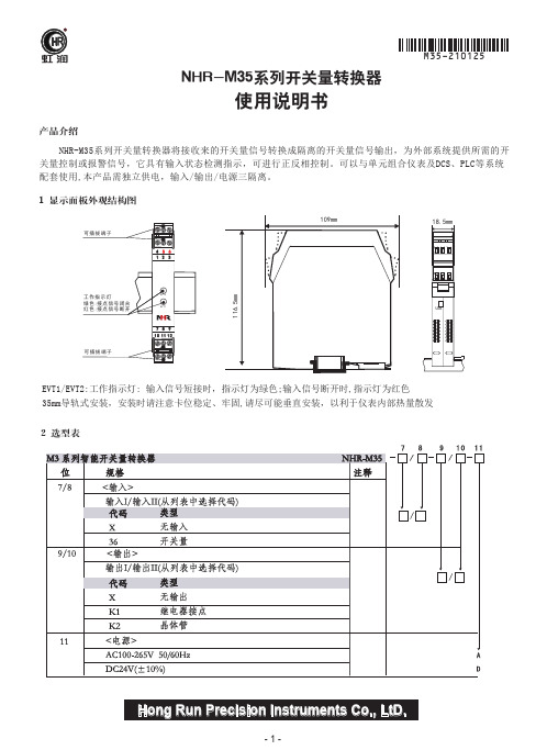
Hong Run Precision Instruments Co., LtD.NHR-M35系列开关量转换器将接收来的开关量信号转换成隔离的开关量信号输出,为外部系统提供所需的开关量控制或报警信号,它具有输入状态检测指示,可进行正反相控制。
可以与单元组合仪表及DCS、PLC等系统配套使用,本产品需独立供电,输入/输出/电源三隔离。
产品介绍1 显示面板外观结构图2 选型表NHR-M35系列开关量转换器使用说明书EVT1/EVT2:工作指示灯: 输入信号短接时,指示灯为绿色;输入信号断开时,指示灯为红色35mm导轨式安装,安装时请注意卡位稳定、牢固,请尽可能垂直安装,以利于仪表内部热量散发109mm116.5m m18.5mmUSB456321789101112可插拔端子工作指示灯绿色:接点信号闭合红色:接点信号断开可插拔端子EVT1EVT2虹润输入输入信号配电电压短路电流输出输出信号继电器输出继电器响应时间晶体管输出电压输入和输出特性(设置为同相控制时)现场开关闭合或输入回路电流>2.1mA,输出继电器或晶体管导通,通道绿色指示灯亮现场开关开路或输入回路电流<1.2mA,输出继电器或晶体管不导通,通道红色指示灯亮输入和输出反相控制设置由面板拨码开关J5设置电源电源功耗其它参数绝缘电阻(输入/输出/电源之间)绝缘强度(输入/输出/电源之间)工作温度相对湿度保存温度安装方式外形尺寸重量电磁兼容性适用现场设备触点开关、接近开关(频率≤5KHZ)≈8V(开路时)≈8mA继电器或晶体管输出容量:AC220V/10A,DC30V/2A ≤5ms集电极输出时:高电平VCC(≤30V),低电平≤2.5V 发射极输出时:高电平VCC-2.5V,低电平≤0.5VDC24V(±10%),AC100-265V 50/60HzDC24V 单路输出功耗:≤0.8W;双路输出功耗:≤1.2W AC100-265V 单路输出功耗:≤1.0W;双路输出功耗:≤1.4W ≥100MΩ(500VDC时)1500Vrms (1 min,无火花)0~50℃(无凝露、无结冰)25%~85%RH-10~60℃(无凝露、无结冰)35mmDIN导轨安装18.5*109*116.5mm(宽*高*深)约140克符合GB/T18268工业设备应用要求(IEC 61326-1)触点开关、接近开关拨码1、2控制第一路输入,拨码3、4控制第二路输入拨码1:ON,2:OFF,则表示一路同相控制,反之反相控制。
5V继电器隔离模块使用说明书

5V继电器隔离模块使用说明书继电器隔离模块使用说明书【产品展示图片产品展示图片】】继电器隔离模块使用说明引脚说明引脚说明::板子尺寸:(长* 宽*高)52mm*22mm*20mm板子孔距:(长*宽) 34mm*19mm安装孔径:2mm输入端输入端::1、+5V---电源正输入口电源正输入口;;2、IN----信号输入口信号输入口((低电平有效低电平有效,,开启继电器开启继电器));3、GND---电源负输入口电源负输入口。
输出端输出端::1、NC---常闭输出口常闭输出口;;2、COM---公共端口公共端口;;3、NO---常开输出口常开输出口。
简要说明一、尺寸尺寸::长52mmX 宽22mmX 高20mm 二、主要器件主要器件::EL817、DC5V 继电器继电器隔离模块使用说明书电压电压::直流5V-至12V三、可控制10A 250VAC 、10A 30VDC 负载特点特点::1、具有输出信号指示灯具有输出信号指示灯;;2、直接可接单片机输出口直接可接单片机输出口;;3、抗干扰能力强抗干扰能力强,,具有光电隔离具有光电隔离;;4、具有二极管续流保护具有二极管续流保护;;5、可单独控制一台外围设备可单独控制一台外围设备;;6、继电器寿命长可连续吸合10万次万次;;7、外部连线采用旋转压接端子外部连线采用旋转压接端子,,使接线更牢固使接线更牢固;;8、四周有固定安装孔四周有固定安装孔,,方便固定安装方便固定安装。
适用场合适用场合::单片机学习单片机学习、、电子竞赛电子竞赛、、产品开发产品开发、、毕业设计等等附录附录::原理图九九新电子九九新电子网站网站网站:: 淘宝店淘宝店::/。
DMM-5T-2三相多功能面板指示器说明书

designed for versatile monitoring of parameters of a single- or three-phase power supply line. The multimeter allows for high accuracy measurements of all relevant network parameters, such as phase voltages and currents, phase-to-phase voltages, active, reactive, apparent power, power factor. In addition, the multimeter provides a full four-quadrant measurement of ener-gy (both imported and exported) and analyses the distribution of voltage and current harmonics up to and including 63-harmonic.No.Description 1Indicator of the selected network type:»1P2W – 1-phase, 2-wire installation »3P3W – 3-phase, 3-wire installation »3P4W – 3-phase, 4-wire installation 2A bar graph indicating the power consumption of each phase 3DMD – displays the demand indication4AVG – displays the average value from all of the phases5Power display indicator:»P – active power»Q – reactive power »S – apparent power6Signalling of the operation of the pulse outputs7Displaying values:»MIN – minimum value »MAX – maximum value8Indicators of measured values9Indicators of RS-485 communication10Indicates the units of displayed measured values11Indicators:»PF – power factor»THD % – the percentage of total harmonic distortion »Hz – frequency12Graphical power factor indicator13Energy consumption indicator including unit14Indicates the type of energy displayed in field 13:»TOTAL – total energy consumption»IMP – energy imported»EXP – energy exportedInstallation and connection of the multimeter should be carried out by the qualified personnel. All available pro-tection requirements must be taken into account.Power supply voltage. The DMM-5T-2 Multimeter is po-wered via the V1, V2, V3, N voltage terminals and does not require an auxiliary power supply. It is recommen-ded to protect the power supply and voltage circuits of the meter with a 1 A fuse-link.Measuring voltage. The maximum value of the me-asuring voltage must not exceed 280 V AC (phase voltage between the L-N terminals) or 500 V AC (phase voltage between the L-L terminals). Exceeding the maximum va-lue of the measuring voltage may damage the device.Measuring current. The multimeter is designed for in-direct current measurement using current transformers with a 5 A secondary current. If the measuring current exceeds 6 A, it may damage the device.Environmental conditions. The device is designed tooperate at a temperature of -25÷55°C with air humiditybelow 90%. Exceeding the operating limits may result inincorrect operation or damage to the multimeter.An opening of 92×92 mm should be made in the panel, and the thickness of the material used to make the panel should not ex-ceed 5 mm.Insert the multimeter from the front of the panel with all wires disconnected and press it against the surface of the panel. After mounting the multimeter on the panel, the cabling can be connected.View of the multimeter from the side of the connector platesVOLTAGE L1Voltagemeasu-rementchain,powersupplyof themetertage terminals to the measuredinstallation must be adapted tothe type of measured network, inaccordance with the diagrams onpages 10, 11, 12.L2L3The voltage circuits of the metershould be protected with a 1 Aslow blow fuse-link.NCURRENT I1↑I1↓Currentmeasu-rementchainThe current measuring chainis adapted to connect currenttransformers with 5 A secondarycurrent and minimum powerof 0.5 VA.I2↑I2↓The current input of the metermarked with the ↓ symbolshould be connected to theS1 terminal of the currenttransformer. The current inputof the meter marked with the ↑symbol should be connected tothe S2 terminal of the currenttransformer.cont. CURRENT I3↑I3↓Currentmeasu-rementchainTo prevent high potentials fromoccurring at the transformerterminals, all S2 terminals ofthe transformers should beearthed.PULSE P1+COMP2+PulseoutputsPassive pulse outputs (opencollector), Class A compliantIEC 62053-31P1 – programmablepulse output (functionand number of pulses)P2 – energy consumption indi-cation (3200 pulse/kWh)COM – common ground of P1and P2 outputs.Maximum load of a singleoutput pulse:voltage ≤30 V current ≤20 mARS-485A+Commu-nicationinterfaceIt is recommended to useshielded cables dedicated toRS-485 communication.B-Terminating resistors with a va-lue of 120Ω must be connectedat the ends of the bus.GUp to 32 devices can beconnected in one branch of theRS-485 bus.3P4W system - 3-phase, 4-wire network, semi-indirect measurementConnection diagrams for other network systems andmeasurement variants are available in the full device manual that can be downloaded from .pl from the product page.»Voltage, current, activeand reactive power forindividual phases;»In configuration mode,return to the previousmenu by pressingthe ESC.»Enabling/disabling ofthe automatic viewswitching mode withmeasured values.»Phase voltages;»Phase-to-phase voltage;»Phase currents;»Voltage and currentharmonics (sum) byphase;»Phase sequence;»In configuration modeor value selectionmode– button Left.»Voltage harmonics (from1 to 63), change of thedisplayed harmonicsusing the Up or Downbuttons.»Frequency and totalpower factor;»Power factor by phase;»Current harmonics(from 1 to 63), changeof the displayed har-monics using the Up orDown buttons.»Maximum and averagecurrent consumption;»While in configurationor value selectionmode - the Up button(increasing the value).»Current harmonics(from 1 to 63), changeof the displayed har-monics using the Up orDown buttons.»Active power by phase;»Reactive power byphase;»Apparent power byphase;»Total active, reactiveand apparent power;»While in configurationor value selectionmode – the DOWNbutton (decreasing thevalue)»Operating time of thedevice»Total active energy;»Total reactive energy;»Imported activeenergy;»Imported reactiveenergy;»Exported activeenergy;»Exported reactiveenergy;»While in configurationor value selectionmode – the Rightbutton.»Entering configurationmode;»Confirming parametervalue.Measuring systemnetwork 1P2W – 1-phase, 2-wire3P3W – 3-phase, 3-wire3P4W – 3-phase, 4-wire Current measurementrated current In 0.25÷5 (6) A* * the actual value of the measured current will depend on the size of the current transformers usedCurrent measurement cont.power consumption 0,5 VA/phase Voltage measurementmeasurement range 58÷276 V AC (phase voltage L-N)100÷480 V AC (phase-to-phase voltage L-L) frequency 45÷55 Hz Operating conditionstotal power consumptiontypical ≤2 VA temporary ≤15 VA operating temperature -25÷55°C storing temperature -40÷70°C relative humidity 0÷95%(without condensation or aggressive gases) class of contamination 2 housing flammability UL94–V0 ingress protectionfront IP54 back IP20 case size 96×96×62 mm size of the mounting hole 92×92 mm panel thickness 1÷5 mm Communicationpulse outputs 2 RS-485 Modbus RTU baud-rate 2400/4800/9600/19200/38400 bps parity BRAK/EVEN/ODDstop bits 1, 2VoltageCurrent0÷9999.9 kA0,2 % Power factor-1÷1 1 % Frequency45÷65 Hz0,2 % Active power0÷3600 MW0,5 % Reactive power0÷3600 MVAr 1 % Apparent power0÷3600 MVA 1 %Active energy0÷9999999.9 kWhKlasa 0,5S (IEC62053-22)Reactive energy0÷9999999.9 kVArh 2 % Phase angle 2 % Total harmonicdistortion of currentand voltage (total orindividual from 2÷63harmonic)0÷100% 2 %of purchase. The warranty is only valid with proof of purchase. Contact your dealer or contact us directly.with the essential requirements of The Low Voltage Directive (LVD) 2014/35/EU and the Electromagnetic Compatibility (EMC) Directive 2014/30/UE. The CE Declaration of Conformity, along with the references to the standards in relation to which confor-mity is declared, can be found at .pl on the product page.。
PX-GL3.5音频隔离器说明书
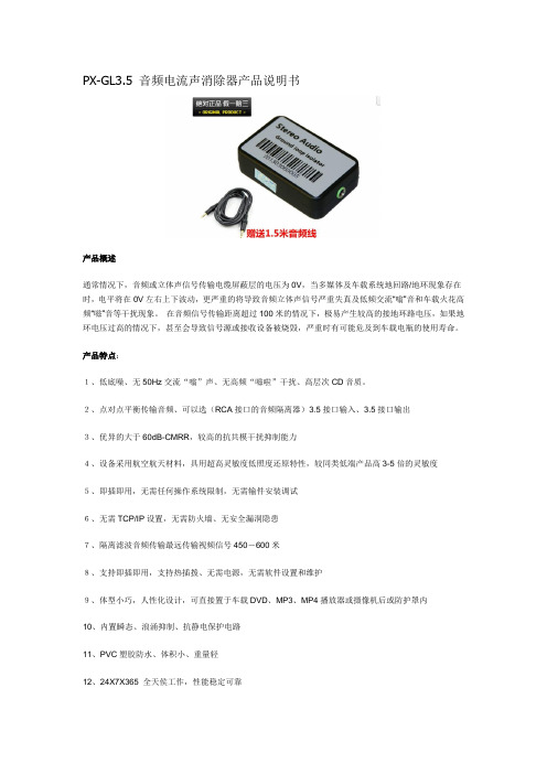
PX-GL3.5 音频电流声消除器产品说明书产品概述通常情况下,音频或立体声信号传输电缆屏蔽层的电压为0V,当多媒体及车载系统地回路/地环现象存在时,电平将在0V左右上下波动,更严重的将导致音频立体声信号严重失真及低频交流“嗡”音和车载火花高频“嗞”音等干扰现象。
在音频信号传输距离超过100米的情况下,极易产生较高的接地环路电压,如果地环电压过高的情况下,甚至会导致信号源或接收设备被烧毁,严重时有可能危及到车载电瓶的使用寿命。
产品特点:1、低底噪、无50Hz交流“嗡”声、无高频“嗞啦”干扰、高层次CD音质。
2、点对点平衡传输音频、可以选(RCA接口的音频隔离器)3.5接口输入、3.5接口输出3、优异的大于60dB-CMRR,较高的抗共模干扰抑制能力4、设备采用航空航天材料,具用超高灵敏度低照度还原特性,较同类低端产品高3-5倍的灵敏度5、即插即用,无需任何操作系统限制,无需输件安装调试6、无需TCP/IP设置,无需防火墙、无安全漏洞隐患7、隔离滤波音频传输最远传输视频信号450-600米8、支持即插即用,支持热插拨、无需电源,无需软件设置和维护9、体型小巧,人性化设计,可直接置于车载DVD、MP3、MP4播放器或摄像机后或防护罩内10、内置瞬态、浪涌抑制、抗静电保护电路11、PVC塑胶防水、体积小、重量轻12、24X7X365 全天侯工作,性能稳定可靠13、尺寸:长*宽*高(54*34*15) mm产品性能指标:输入输出隔离绝缘耐压:300Vp-p以上多媒体立体声隔离静噪器特性:设备插损<0.5dB回损:大于18dB接口: 3.5mm母头阻抗:300欧姆Min-600欧姆Max(输入-输出、输入电平:0.5Vp-p(Min)-1Vp-p - 3Vp-p (Max)、模拟地环路隔离及静噪处理音频响应带宽:50Hz-15KHz共模抑制:大于68dB@1KHz立体声通道隔离度:62dB工作温度:-10℃-85℃(车规级可选)储藏温度:-30℃-70℃适用音频格式:模拟立体声产品连接示意图:注:此产品不分输入输出,只需串接在音响线路中即可.。
温度隔离变送器消除变频器干扰

经常接到客户电话咨询,西门子37-300PLC接受热电偶信号时,如果现场所有动力设备停止工作时,PLC能准确接收热电偶的信号,读取数据也比较稳定,但是当现场的变频器启动后,PLC读取的数据就是出现异常波动,长庆油田水泥添加剂厂混合搅拌机的75KW蛟龙变频器启动时,用来测量水泥温度的热电偶会上下波动50多度,有时甚至会超过测量范围,但如果蛟龙电机的变频器停止工作,那么温度显示就正常,上下跳动在1℃以内。
用高速6位半万用表测量发现,变频器不启动时,PLC接收端的信号为16.210mV, 系统触摸屏显示温度375度,温度正常,但如果启动变频器,PLC接收端的信号上下会跳动10多mV,温度显示也有上下200℃的跳动,从此分析,热电偶信号受到变频器的严重干扰因为热电偶信号输出很小(一般在几十个mV),在复杂的工业现场,尤其变频器周围有着很强的电磁干扰,加之热电偶引线较长,极易受到变频器干扰,导致热电偶传输到plc 端口的信号很不稳定。
为此,我们在热电偶输出端,靠近热电偶接线盒处加装XM35T温度隔离变送器,把热电偶输出的mV级小信号在0-1000度范围内变送输出为4-20mA的电流信号,再把电流信号送至PLCmA输入端口,重新设置plc的输入信号,开机后,无论变频器是否启动,PLC读数都很稳定、正常,显然XM35T温度隔离变送器有效的解决了现场变频器对热电偶信号的干扰,并使得信号传输距离可以延长至百米左右。
西安西曼电子科技有限公司生产的XM35T隔离变送器输入、输出、电源是三隔离的,同时输出信号经过高速光电隔离器的隔离,有效的消除周围设备的电磁干扰对热电偶信号的影响,成功的解决了变频器对小信号的干扰。
在解决问题时,我们也发现有几个热电偶传感器的工艺存在缺陷,热电偶的两根金属丝和外部不锈钢保护壳是接触的,这样一来,热电偶的金属丝就会和整个设备接触,有时用手去摸设备外壳,由于静电的原因,热电偶的输出也会有跳动,有的用户如果把热电偶的外层屏蔽网接地,那么热电偶将会被短路,造成无法测量。
信号隔离器说明书——苏州迅鹏

苏州迅鹏仪器仪表有限公司
XP 系列信号隔离器
概述
XP 系列信号隔离器 (一进一出,一进二出)是在自动化控制系统中对各种工业信号变送、转换、隔离、传输、运算的仪表,可 与各种工业传感器配合,取回参数信号,隔离变送传输,满足用户本地监视远程数据采集的需求。广泛应用于机械、电气、电信、 电力、石油、化工、钢铁、污水处理、楼宇建筑等领域的数据采集、信号传输转换、PLC、DCS 等工业测控系统,用来完善和补充 系统模拟∣/O 插件功能,增加系统适用性和现场环境的可靠度。
此系列信号隔离器还包含无源隔离器来自苏州迅鹏仪器仪表有限公司
w
7(/
.s
)$;
ur
po
n. c
om
95(L)*23(W) *120(H)mm
35mm 导轨卡装;主机与底座可以插拔分离
此系列信号隔离器还包含无源隔离器 特点
精度:≤±0.1%RO 测量:直流电压、直流电流等
隔离:输入、输出、电源三方完全隔离,抗干扰能力强 电源:DC24V 或 AC220V 支持带电热插拨装卸方便、精度高、线形度高、抗干扰性强、长期工作的稳定性
选型代码
w w
苏州迅鹏仪器仪表有限公司
w
7(/
.s
ur
)$;
po
n. c
om
XP系列信号隔离器
外形尺寸
接线图
w w
常用规格实例
Model:XP-A-A420-2A420-D (等同于 XP-A-A420-A420A420-D ,可以简写成 XP-A-A420-2A420-D) Input: 4~20mAdc Output1:4~20mAdc ; Output2:4~20mAdc Aux.power:DC24V 描述: 此产品为一进二出信号隔离器, 一路 4~20mA 直流信号输入 , 隔离变送输出两路信号, 输出1为 4~20mAdc 直流电流信号; 输出 2也为 4~20mA 直流电流信号;辅助电源为直流 24V.
信号隔离器系列安全操作及保养规程
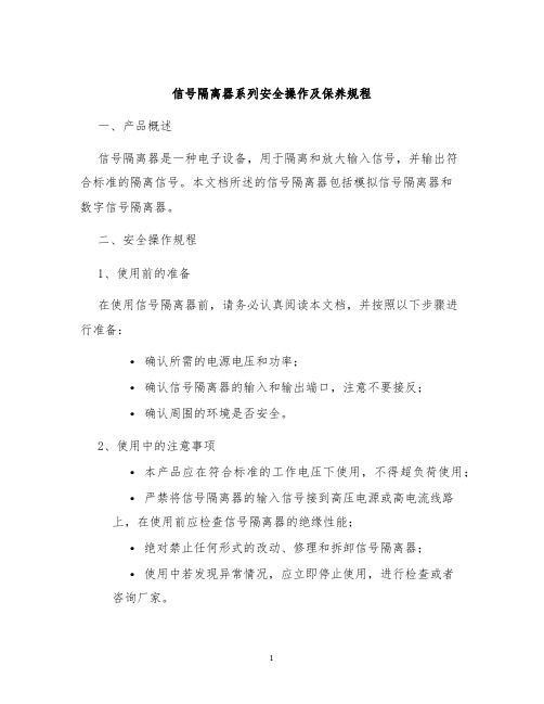
信号隔离器系列安全操作及保养规程一、产品概述信号隔离器是一种电子设备,用于隔离和放大输入信号,并输出符合标准的隔离信号。
本文档所述的信号隔离器包括模拟信号隔离器和数字信号隔离器。
二、安全操作规程1、使用前的准备在使用信号隔离器前,请务必认真阅读本文档,并按照以下步骤进行准备:•确认所需的电源电压和功率;•确认信号隔离器的输入和输出端口,注意不要接反;•确认周围的环境是否安全。
2、使用中的注意事项•本产品应在符合标准的工作电压下使用,不得超负荷使用;•严禁将信号隔离器的输入信号接到高压电源或高电流线路上,在使用前应检查信号隔离器的绝缘性能;•绝对禁止任何形式的改动、修理和拆卸信号隔离器;•使用中若发现异常情况,应立即停止使用,进行检查或者咨询厂家。
3、维护保养•在使用前应检查信号隔离器的各部件是否正常,保证各部件没有松动、磨损、风化等缺陷;•信号隔离器内部具有高精度和高灵敏度的元件,保持内部清洁和干燥十分重要;•不要在信号隔离器上堆放或放置其他物品,保持通风和散热的状态;•信号隔离器需要定期检查和维护保养,建议每年对设备进行一次全面的检修。
三、处理故障1、故障现象•输入信号丢失或出现异常;•输出信号没有反应或输出异常;•信号隔离器本身发出异常的声音。
2、处理方法•首先检查输入和输出端口是否接反或者接错,调整后重新测试;•如果仍出现故障,可以尝试更替输入信号源或检查信号源的电缆或连接器;•如果以上方法均无法解决问题,建议拆卸信号隔离器进行检查或者咨询专业人士。
四、注意事项1、安全防范使用信号隔离器时,请注意以下安全事项:•请勿打开信号隔离器盖板,不懂维修的用户请勿自行拆卸;•请勿接触信号隔离器的内部元器件,以免发生触电事故;•请勿将信号隔离器安装在湿度较大或者通风不良的地方。
•如需使用外部电源,请务必使用正规的产品。
2、保养要点•请勿在信号隔离器表面擦拭任何化学药品;•请勿在信号隔离器上重压或敲打;•请勿将信号隔离器暴露在阳光下或者长时间在高温环境下使用。
电流信号隔离模块使用说明书

4~20mA信号隔离模块使用说明书0 概述在矿用自动化系统中,用于现场数据采集的传感器多为本质安全型,或者传感器信号输出为本质安全型。
而系统的中央控制设备,比如PLC就地控制箱(微机箱),则为非本质安全型。
若将本安的传感器与非安的就地控制箱直接电气连接,便破坏本安设备的安全性能,这是不符合安全要求的。
4~20mA信号隔离模块可实现电流直流信号的线性隔离以及本安与非安之间信号的线性传输,同时可扩充传感器输出端口的驱动能力。
1 特点输入范围:2~30mA二线制电流环;输出范围:2~30mA二线制电流环;输入电阻:24Ω;输出负载能力:>500Ω;线性度:±0.5%;传输特性:Iin/Iout=1;工作电压:12~27VDC;绝缘特性:>109Ω;输入输出耐压:2.5KV.1min;图1 模块照片工作温度:-25 ℃~ +85℃。
2 应用4~20mA电流环信号隔离;0~5Hz频率信号隔离;200~1000Hz模拟信号隔离。
3 外形尺寸外形尺寸详见图2。
折断处图2 外形尺寸模块设计为四合一的方式,既一个隔离板上有四个完全相同的单元,每个单元可实现一路模拟信号的隔离。
单元与单元之间设计为可折断方式,从折断处可拆分为单独的功能单元,方便较小系统以及大系统的使用。
图 3 接线端子含义4 电气特性4.1 电气特性参数名称符号条件最小值典型值最大值单位备注工作电压Vcc 12 24 27 V最小输入I inmin 1.6 1.8 2.0 mA最大输入I inmax Vcc=24VDC 30 32 34 mA最大负载R Lmax Vcc=24VDC,Iin=30mA500 Ω工作温度-25 85 ℃贮运温度-55 125 ℃传递系数K 0.97 1.03线性度0.5%传递系数温度漂移0.024.2 典型图表5 典型应用以及连线方法5.1 接线端子含义接线端子及其含义如图3所示,个接线端子的定义如下:信号输入+:In+;信号输入-:In-;信号输出+:Out+;信号输出-:Out-。
XM3 D-sub 接口器系列用户指南说明书
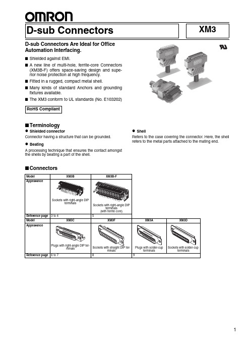
XM3 D-sub ConnectorsD-sub Connectors Are Ideal for OfficeAutomation Interfacing.■Shielded against EMI.■A new line of multi-hole, ferrite-core Connectors(XM3B-F) offers space-saving design and supe-rior noise protection at high frequency.■Fitted in a rugged, compact metal shell.■M any kinds of standard Anchors and groundingfixtures available.■The XM3 conform to UL standards (No. E103202)■Terminologyz Shielded connectorConnector having a structure that can be grounded.z BeatingA processing technique that ensures the contact amongst the shells by beating a part of the shell.z ShellRefers to the case covering the connector. Here, the shell refers to the metal parts attached to the mating end.■ConnectorsRoHS CompliantSockets with right-angle DIPterminalsSockets with right-angle DIPterminals(with ferrite core)3 to 45XM3C XM3F12D-sub Connectors XM3■Ratings and Characteristics■Materials and Finish■Applicable WiresThe applicable wires for solder cup terminals are AWG 22 to 28 (solid or stranded).ItemModel XM3AXM3B XM3B-FAll XM3C models except for those with 37 pins XM3D XM3FXM3C models with 37 pinsRated current 5 A 3 ARated voltage 300 VACContact resistance 15 m Ω max. (at 20 mVDC, 100 mA max.)Insulation resistance 1,000 M Ω min. (at 500 V DC)Dielectric strength 1,000 VAC for 1 min (leakage current: 1 mA max.)Insertion durability200 timesAmbient operating temperature−55 to 105°C (with no condensation or icing)Item ModelXM3BXM3B-FXM3CXM3FXM3AXM3DHousingPBT (UL94 V-0)/blackPBT (UL94 V-0)/Milky white ContactsMating endPhosphor bronze/nickel base, gold plated Bronze/nickel base, gold platedPhosphor bronze/nickel base, gold plated TerminalsPhosphor bronze/nickel base, tin platedPhosphor bronze/nickel base, tin platedBronze/nickel base, tin platedPhosphor bronze/nickel base, tin platedShellSteel/nickel platedD-sub Connectors XM33XM3B Sockets with Right-angle DIP Terminals■Model Number Legend■Dimensions(unit: mm)1.Number of contacts 09: 9 contacts 15: 15 contacts 25: 25 contacts 37: 37 contacts2.Anchor specifications 1: With Anchor 25: No anchors3.Anchor screw specifications 1: M2.6 × 0.45 metric screws 3: #4-40 UNC inch screws 0: No anchors4.Grounding Fixture1: T ap Hole Grounding Fixture 2: Lock Pin Grounding Fixture Note:Anchors and GroundingFixtures are not supplied if 2, 3,and 4 are blank.T w o, 3.1 dia.25-contact model sho w n a b o v e.(W ith anchor 2, Lock Pin, Gro u nding Fixt u res)Mo u nting holes (t = 1.6 mm, b ottom v ie w )T w o, 3.2 ±0.1 dia.1 ±0.1 dia.DimensionsNo. of contacts Dimensions (mm)A B C D E F 930.824.9916.3010.968.22 2.741539.133.3224.6519.1816.44 2.742553.047.0438.3533.1230.36 2.763769.363.5054.8049.6846.922.76Note:XM3B Sockets were manufactured in accordancewith JIS X 5101. Terminal pitches are a mixed ar-rangement of 2.77- and 2.74-mm contacts on 25-and 37-contact models as specified in the JIS standard. A pitch of 2.76 mm is recommended for the mounting holes because of the more advanced numerical control available today. This is sufficient to avoid any problems.XM3B-@@22 (No anchors, no grounding fixtures)XM3B-@@22-501 (No anchors, Tap Hole Grounding Fixtures)XM3B-@@22-111 (With Anchor 2 (See note 1.), Tap Hole Grounding Fixtures)XM3B-@@22-131 (With Anchor 2 (See note 2.), Tap Hole Grounding Fixtures)XM3B-@@22-502 (No anchors, Lock Pin Grounding Fixtures)XM3B-@@22-112 (With Anchor 2 (See note 1.), Lock Pin Grounding Fixtures)XM3B-@@22-132 (With Anchor 2 (See note 2.), Lock Pin Grounding Fixtures)Note:1.Metric screws (M2.6 × 0.45)2.Inch screws (#4-40 UNC)4D-sub Connectors XM3■Ordering InformationNote:e the XM3B-@@22 (No anchors or grounding fixtures) in combination with suitable Anchors and Grounding Fixtures.2.T wo M 3 × 0.5 T ap Hole Grounding Fixtures and an M3 × 0.5 Lock Pin Grounding Fixture for the Anchor side are provided.3.For other models with Anchors or Grounding Fixtures, contact your OMRON representative. For accessories, refer to Accessories (Sold Separately) in the XM2/XM3 datasheet.AppearanceAccessoriesNo. of contacts Anchor 2 andTap Hole Grounding FixturesAnchor 2 andLock Pin Grounding FixturesNo anchors or grounding fixtures (See note 1.)XM2Z-0011 Anchor 2 (M2.6 × 0.45 metric screws)---XM2Z-0061Tap Hole Grounding Fixtures XM2Z-0062Lock Pin Grounding Fixtures ---9XM3B-0922-111XM3B-0922-112XM3B-092215XM3B-1522-111XM3B-1522-112XM3B-152225XM3B-2522-111XM3B-2522-112XM3B-252237XM3B-3722-111XM3B-3722-112XM3B-3722Accessories No. of contacts XM2Z-0013 Anchor 2 (#4-40 UNC inch screws)XM2Z-0061Tap Hole Grounding Fixtures XM2Z-0062Lock Pin Grounding Fixtures 9XM3B-0922-131XM3B-0922-13215XM3B-1522-131XM3B-1522-13225XM3B-2522-131XM3B-2522-13237XM3B-3722-131XM3B-3722-132AppearanceAccessories No. of contacts No anchors, withTap Hole Grounding FixturesNo anchors, withLock Pin Grounding FixturesNo anchorsXM2Z-0061Tap Hole Grounding Fixtures XM2Z-0062Lock Pin Grounding Fixtures9XM3B-0922-501XM3B-0922-50215XM3B-1522-501XM3B-1522-50225XM3B-2522-501XM3B-2522-50237XM3B-3722-501XM3B-3722-502Tap Hole Gro u nding Fixt u reAnchor 2Lock Pin Gro u nding Fixt u reAnchor 2Tap Hole Gro u nding Fixt u reLock Pin Gro u nding Fixt u reD-sub Connectors XM35XM3B-F Sockets with Right-angle DIP Terminals and Ferrite Cores■Dimensions(unit: mm)■Ordering Information25-contact model sho w n a b o v e. (W ith Tap Hole Gro u nding Fixt u res)T w o, M3T w o, M3Ferrite core T ap Hole Gro u nding Fixt u reMo u nting holes (t = 1.6 mm, b ottom v ie w)T w o, 3.2 ±0.1 dia.1 ±0.1 dia.Sockets with Right-angle DIP Terminals XM3B-@@22-501F(With Tap Hole Grounding Fixtures)DimensionsNo. of contacts Dimensions (mm)A B C D E F G 930.824.9916.3010.968.22 2.7414.31539.133.3224.6519.1816.44 2.7422.02553.047.0438.3533.1230.36 2.7636.53769.363.5054.8049.6846.922.7653.3Note:XM3B Sockets were manufactured in accordancewith JIS X 5101. Terminal pitches are a mixed ar-rangement of 2.77- and 2.74-mm contacts on 25-and 37-contact models as specified in the JIS standard. A pitch of 2.76 mm is recommended for the mounting holes because of the more advanced numerical control available today. This is sufficient to avoid any problems.AppearanceAccessories No. of contacts Tap Hole Grounding FixturesXM2Z-0061Tap Hole Grounding Fixtures9XM3B-0922-501F 15XM3B-1522-501F 25XM3B-2522-501F 37XM3B-3722-501FT ap Hole Gro u nding Fixt u re6D-sub Connectors XM3XM3C Plugs with Right-angle DIP Terminals■Model Number Legend■Dimensions(unit: mm)1.Number of contacts 09: 9 contacts 15: 15 contacts 25: 25 contacts 37: 37 contacts2.Anchor specifications 1: With Anchor 25: No anchors3.Anchor screw specifications 1: M2.6 × 0.45 metric screws 3: Inch screws 0: No anchors4.Grounding Fixture1: T ap Hole Grounding Fixture 2: Lock Pin Grounding Fixture Note:Anchors and GroundingFixtures are not supplied if 2, 3, and 4 are blank.DIP TerminalsXM3C-@@22 (No Anchors or Grounding Fixtures)XM3C-@@22-501 (No Anchors, with Tap Hole Grounding Fixtures)XM3C-@@22-502 (No Anchors, with Lock Pin Grounding Fixtures)XM3C-@@22-111 (With Anchor 2 and Tap Hole Grounding Fixtures)XM3C-@@22-112 (With Anchor 2 and Lock Pin Grounding Fixtures)D-sub Connectors XM37■Ordering InformationNote:The XM3C-@@22-111/-112 with Anchor 2 (M2.6 × 0.45) and Grounding Fixtures as well as the XM3C-@@22-501/-502 with Grounding Fix-tures and no Anchor are available as standard models. T wo M3 × 0.5 T ap Hole Grounding Fixtures and an M3 × 0.5 Lock Pin Grounding Fixture for the Anchor side are provided.Contact your OMRON representative for other anchor and grounding fixture specifications. See Accessories (Sold Separately) of XM2/XM3for details on accesories.Tap Hole Grounding Fixtures and Lock Pin Grounding Fixtures are not sold separately.AppearanceAccessoriesNo. of contacts Anchor 2 and Tap Hole Grounding FixturesAnchor 2 and Lock Pin GroundingFixturesNo anchors or Grounding FixturesXM2Z-0011 Anchor 2 (M2.6 × 0.45 metric screws)---Tap Hole Grounding FixturesLock Pin Grounding Fixtures ---9XM3C-0922-111XM3C-0922-112XM3C-092215XM3C-1522-111XM3C-1522-112XM3C-152225XM3C-2522-111XM3C-2522-112XM3C-252237XM3C-3722-111XM3C-3722-112XM3C-3722AppearanceAccessories No. of contacts No anchors, with Tap Hole GroundingFixturesNo anchors, with Lock Pin GroundingFixturesNo anchorsTap Hole Grounding Fixtures Lock Pin Grounding Fixtures 9XM3C-0922-501XM3C-0922-50215XM3C-1522-501XM3C-1522-50225XM3C-2522-501XM3C-2522-50237XM3C-3722-501XM3C-3722-502Anchor 2Tap Hole Gro u nding Fixt u reAnchor 2Lock Pin Gro u nding Fixt u reT ap Hole Gro u nding Fixt u reLock Pin Gro u nding Fixt u reXM3F Sockets with Straight DIP Terminals■Dimensions(unit: mm) Straight DIP TerminalsXM3F-@@20 XM3F-@@20-112(With Anchor and Lock Pin Grounding Fixtures)■Ordering Information8D-sub Connectors XM3XM3A Plugs with Solder-cup TerminalsXM3D Sockets with Solder-cup Terminals■Dimensions(unit: mm)D-sub Connectors XM39。
信号隔离器的使用方法

信号隔离器的使用方法1.引言1.1 概述信号隔离器是一种应用广泛的电子设备,用于处理电路中的信号传输和隔离问题。
它被广泛应用于工业自动化、电力系统、通信系统等领域,起到了至关重要的作用。
信号隔离器的主要作用是将电路中的信号进行隔离,防止信号传输时的干扰和噪音污染。
在很多情况下,不同电路之间的信号传递会导致互相影响和信号失真的问题。
这往往会导致电路的工作不稳定或者数据错误的传输。
而信号隔离器通过采用特定的电路设计和信号处理技术,能够有效地解决这些问题。
信号隔离器的工作原理基于电气隔离技术,它将输入信号电路和输出信号电路之间通过绝缘层进行隔离,使得两个电路之间的信号无法直接相互影响。
这种隔离方式能够有效降低噪音干扰、电磁干扰等因素对信号传输的影响,提高系统的稳定性和可靠性。
在信号隔离器的使用方法上,首先需要选择合适的信号隔离器类型和规格。
根据实际需求和电路特点,选择适合的隔离器能够更好地满足需求。
其次,在安装和连接时,需要按照隔离器的说明书进行正确的操作,并且保证信号输入端和输出端的连接正确可靠,避免接触不良等问题。
此外,使用信号隔离器时还需要注意电源供应和电气安全。
合理选择和配置电源,确保信号隔离器的正常工作和长期稳定性。
同时,在操作时要注意遵守电气安全规范,避免电路短路、过载等问题的发生。
总之,信号隔离器是一种重要的电子设备,其使用方法和原理对于保证电路信号传输和隔离的稳定性具有重要意义。
合理选择隔离器类型、正确安装和连接、注意电源供应和电气安全等方面的注意事项,能够保证信号隔离器的正常工作,并有效解决信号传输中的干扰和噪音问题。
希望本文能够帮助读者更好地理解信号隔离器的基本概念和使用方法,为相关领域的应用提供参考和指导。
1.2 文章结构文章结构部分:文章将从三个部分进行展开,即引言、正文和结论。
引言部分将首先概述信号隔离器的基本情况,介绍其用途和作用。
接着,探讨文章的结构,即本文将通过对信号隔离器的使用方法进行详细介绍,以使读者能够全面了解其使用要点。
Eaton MTLx532 脉冲隔离器说明书
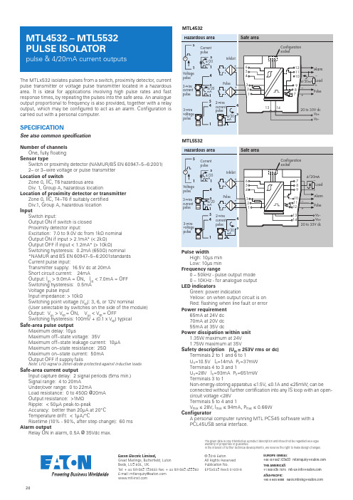
24© 2016 EatonAll Rights Reserved Publication No.Eaton Electric Limited,Great Marlings, Butterfield, Luton Beds, LU2 8DL, UK.Tel: + 44 (0)1582 723633 Fax: + 44 (0)1582 422283E-mail:********************EUROPE (EMEA):+44(0)******************************THE AMERICAS:+********************************ASIA-PACIFIC:+*********************************The given data is only intended as a product description and should not be regarded as a legal warranty of properties or guarantee.In the interest of further technical developments, we reserve the right to make design changes.DR AF TThe MTLx532 isolates pulses from a switch, proximity detector, current pulse transmitter or voltage pulse transmitter located in a hazardous area. It is ideal for applications involving high pulse rates and fast response times, by repeating the pulses into the safe area. An analogue output proportional to frequency is also provided, together with a relay output, which may be configured to act as an alarm. C onfiguration is carried out with a personal computer.SPECIFICATIONSee also common specificationNumber of channelsOne, fully floating Sensor typeSwitch or proximity detector (NAMUR/BS EN 60947–5–6:2001)2– or 3–wire voltage or pulse transmitter Location of switchZone 0, IIC, T6 hazardous areaDiv. 1, Group A, hazardous locationLocation of proximity detector or transmitterZone 0, IIC, T4–T6 if suitably certified Div.1, Group A, hazardous location InputSwitch input:Output ON if switch is closed Proximity detector input:Excitation: 7.0 to 9.0V dc from 1kΩ nominal Output ON if input > 2.1mA* (< 2kΩ) Output OFF if input < 1.2mA* (> 10kΩ)Switching hysteresis: 0.2mA (650Ω) nominal *NAMUR and BS EN 60947–5–6:2001standards Current pulse input:Transmitter supply: 16.5V dc at 20mA Short circuit current: 24mAOutput: I in > 9.0mA = ON, I in < 7.0mA = OFF Switching hysteresis: 0.5mA Voltage pulse inputInput impedance: > 10kΩSwitching point voltage (V sp ): 3, 6, or 12V nominal(User selectable by switches on the side of the module)Output: V in > V sp = ON, V in < V sp = OFFSwitching hysteresis: 100mV + (0.1 x V sp ) typical Safe-area pulse outputMaximum delay: 10µsMaximum off–state voltage: 35VMaximum off–state leakage current: 10µA Maximum on–state resistance: 25ΩMaximum on–state current: 50mA Output OFF if supply failsNote: LFD signal is Zener-diode protected against inductive loadsSafe-area current outputInput capture delay: 2 signal periods (5ms min.)Signal range: 4 to 20mAUnder/over range: 0 to 22mALoad resistance: 0 to 450Ω @20mA Output resistance: >1MΩRipple: < 50µA peak-to-peakAccuracy: better than 20µA at 20°C Temperature drift: < 1µA/°CRisetime (10% - 90%, after step change): 60 ms Alarm outputRelay ON in alarm, 0.5A @ 35Vdc max.Pulse widthHigh: 10µs min Low: 10µs min Frequency range0 – 50kHz - pulse output mode 0 – 10KHz - for analogue output LED indicatorsGreen: power indicationYellow: on when output circuit is on Red: flashing when line fault or error Power requirement65mA at 24V dc 70mA at 20V dc 55mA at 35V dcPower dissipation within unit1.35W maximum at 24V 1.75W maximum at 35VSafety description (U m = 253V rms or dc)Terminals 2 to 1 and 6 to 1U o =10.5V I o =14mA P o =37mW Terminals 4 to 3 and 1U o =28V I o =93mA P o =651mW Terminals 3 to 1Non-energy-storing apparatus ≤1.5V, ≤0.1A and ≤25mW; can be connected without further certification into any IS loop with an open-circuit voltage <28V Terminals 5 to 4 and 1V max ≤ 28V, I max ≤ 94mA, P max ≤ 0.66W ConfiguratorA personal computer running MTL PCS45 software with a PCL45USB serial interface.MTL5532MTL4532EPSx532 Rev5 010916。
- 1、下载文档前请自行甄别文档内容的完整性,平台不提供额外的编辑、内容补充、找答案等附加服务。
- 2、"仅部分预览"的文档,不可在线预览部分如存在完整性等问题,可反馈申请退款(可完整预览的文档不适用该条件!)。
- 3、如文档侵犯您的权益,请联系客服反馈,我们会尽快为您处理(人工客服工作时间:9:00-18:30)。
五、馈电输出
输出电压:D C 2 2 2 6 V 最大电流:≥6 0 mA
六、性能参数
℃ 综合精度:0 . 2 %/ 2 5 温度系数:±0 . 0 1 5 %/℃ 响应时间:0 . 5 s
二、输入信号:
输入信号变送范围
T 2 0 0~4 0 0℃ 型热电偶R型 热电偶0~1 6 0 0℃ J型 热电偶0~6 5 0℃ WA R 3 2 5热 电偶0~1 3 0 0℃ B型 热电偶2 0 0~1 8 0 0℃ S型 热电偶0~1 6 0 0℃ K型 热电偶0~1 3 0 0℃ E型 热电偶2 0 0~8 0 0℃ P t 1 0 0热 电阻2 0 0~6 0 0℃ C U 5 0热 电阻5 0~1 5 0℃
代码
t-t t-r t-j t-w t-b t-s t-k t-e p100 Cu50
输入信号
0~3 7 5Ω 电阻 D C 0~7 5 mV D c 0~3 0 mV D c 0~5 V D c 0~1 0 V D c 0~2 0 mA D c 0~1 0 mA D c 4~2 0 mA
代码
375 0 - 75 0 - 30 5u 10u 0 - 20 0 - 10 4 - 20
能型信号隔离变送器可以通过手操器更改输入信号和输出信号,对 智 于温度传感器信号,也可以任意设定变送输出的温度范围,以下设定过 程需要有一定的经验销售商进行操作
7
+
电流输出
87+电压输出≥5 0 Nhomakorabea0 KΩ
输出信号电流、电压转换
送器出厂的设定信号为电流输出,如果客户需要电压输出信号,比 变
0 5 v 0 1 0 v
如0 1 0 V,0 5 V等 信号,请把变送器外壳打开,把电路板上的J A V处 两 个插针短路,同时把OUTY参数设定为需要的电压类型
8-
十一、高级设定(经销商或者专业客户可进行操作)
隔离电压:电源/输 入/输 出之间 C A 1 0 0 0 V .一 分钟 热电偶冷端补偿范围:2 0~7 0℃ 热电偶冷端补偿误差:±2℃ 系统稳定时间:4 S
七、输出信号
输出信号 4 2 0 mA 0 2 0 mA 0 1 0 mA 0 5 v 0 . 0 1 5 V ≥5 0 0 KΩ 0 1 0 v 0 . 0 1 5 mA ≤5 0 0Ω 最大漂移 负载能力
inty outy pl ph end
SET
t-t 4 20 0000 2000
t-t 0 20 0001 2001
t-t 10v 0002 2002
5 4
mV 10
GND
同色短路线
R
5 4
mV 10
GND
输出信号类型
SET
变送输出下限
两线制电阻
SET
三线制电阻
变送输出下限
SET
输出配线详解
≤5 0 0Ω 结束 4 2 0 mA 0 2 0 mA 0 1 0 mA
八、使用环境
环境温度:1 0~5 0℃ 环境湿度:0 9 0 % RH(无 结露) 安装导轨:DI N 3 5
九、外形尺寸及结构
8 5 mm
备注:变送范围只在对温度传感器输入时需要填写,电流电压信号按一比一 输出时,不需要填写此项
1 0 5 mm
2 3 mm
四、配电电源
隔离器设计了两种配电电源,客户可按使用现场情况选择 配电电源 A : D C 2 4 V B : A C 2 2 0 V 电压范围 D C 2 2 2 8 V A C 8 5 2 6 5 V 频率、纹波 ≤2 0 mV 5 0 H z 功耗 ≤4 W ≤4 W
三、选型表
型号 X m3 5 T 1: 一入一出 X m3 5 T 2: 一入两出 备注:一入两出只能 DC 24 V供电 输入信号 见技术参数列表 变送范围 ( ~( ℃ ) 变送信号 ~2 1 : D C 4 0 mA ) ~2 2 : D C 0 0 mA ~1 3 : D C 0 0 mA 4 : D C 0 V ~5 5: D C 0 0 V ~1 供电电源 A : D C 2 4 V B : A C 2 2 0 V
1 2 3
7 8 9
1 2 6 1 1 5 1 0 4
隔离变送器
型 号:XM -35 T 工作电源:DC 24 V 输入信号: 变送输出:
西安西曼电子科技有限公司
十、输入接线
1
电源
设定操作如果错误,隔离器工作会出现异常但不会损坏隔离器
7
输出一 输出二
12 11
mA / mV
6 5 4
V R GND
2 3
8 9
输入、输出设定流程
上电初始
+ 10
0 00
SET
输入配线详解
4 10
+
mV mA
4 6
-
4 10
0-10V 0-5V
电
热电偶
输入密码界面
0000 1001
SET
输入信号选择成电流、电压信号时, 后面的设定不会出现PL和PH参数
+
压
+
输入密码1 0 0 1
mA / mV
热电偶
输入信号类型
R
XM 35 T信号隔离变送器
一、特点:
工业级A C / D C ,D C / D C 隔离电源技术,电源、输入、输出1 、输出2 ,四隔离 输出单元增加高速光、电隔离器,提高输出隔离效果,抗干扰能力强 标准D I N 3 5 毫米导轨安装,满足大多数场合使用 可选择1 9 种信号输入,输出类型电流、电压共5 种可选, 热电阻、热电偶信号输入,可任意量程变送,小区间变送精度高