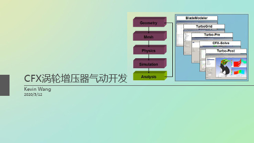
ansys中的bladegen涡轮叶片设计
基于ANSYS和NUMECA的航空发动机涡轮风扇叶片结构仿真分析
基于ANSYS和NUMECA的航空发动机涡轮风扇叶片结构仿真分析林静;潘苏瑜【摘要】本文通过UG软件对NASA Rotor67风扇叶片进行建模,使用ANYSY对其进行离心静变形仿真分析,运用NUMECA对其进行气动力仿真分析,得出叶片在离心力和气动力作用下的变形情况.%Based on the UG software to NASA Rotor67 fan blade modeling, the ANYSY on it from Harbin deformation simulation analysis, using NUMECA to aerodynamic simulation analysis, draw a leaf under the action of centrifugal force and deformation of the situation.【期刊名称】《现代制造技术与装备》【年(卷),期】2016(000)001【总页数】2页(P70-71)【关键词】涡轮风扇叶片;NASA;Rotor67;UG;NUMECA;仿真【作者】林静;潘苏瑜【作者单位】华侨大学机电及自动化学院,厦门 361021;华侨大学机电及自动化学院,厦门 361021【正文语种】中文涡扇发动机,尤其是高涵道比涡扇发动机的风扇叶片是发动机性能的重要衡量标准之一。
因为其产生的推力是涡扇发动机外涵道推力的全部来源。
风扇叶片是涡轮风扇发动机的重要零件。
NASA Rotor67是NASA Lewis研究中心设计的二级风扇中第一级轴流跨声速转子,是为数不多有详细公开发表测试数据的算例。
该风扇被广泛应用于气动计算。
本文选取跨声速风扇叶片NASA Rotor67叶片为算例,运用UG软件进行建模,利用ANSYS对其进行离心静变形仿真分析,利用NUMECA对其进行气动仿真分析。
为了缩短计算时间,提高效率,转子叶片绕旋转轴转动a=2π/N(N为叶片数)。
涡轮叶片气动设计软件BladeDesign
涡轮叶片气动设计软件BladeDesign李剑白;卿雄杰;周山;曾军【摘要】Turbine blade aerodynamic design software BladeDesign which integrates three key design parts: cascade geometry design, S1 flow surface calculation and blade stack greatly improves the designing efficiency of turbine components. The cascade profile design%涡轮叶片气动设计软件BladeDesign将涡轮气动设计中迭代最频繁的叶栅几何设计、s1流面计算、叶片积叠三个环节集成起来,极大地提高了涡轮部件设计的效率。
叶栅型线设计采用目前流行的Bezier曲线,叶栅造型方法充分考虑了工程实际。
集成的S1流面计算网格划分采用ANSYS ICEM CFD 11.0,分析采用ANSYS CFX 11.0。
软件提供了与ANSYS TurboGrid的接口,用于生成叶片排的全三维流场计算网格。
【期刊名称】《燃气涡轮试验与研究》【年(卷),期】2011(000)003【总页数】6页(P11-15,6)【关键词】涡轮叶片;气动设计;参数化;贝赛尔曲线;CFD【作者】李剑白;卿雄杰;周山;曾军【作者单位】中国燃气涡轮研究院,四川成都610500;中国燃气涡轮研究院,四川成都610500;中国燃气涡轮研究院,四川成都610500;中国燃气涡轮研究院,四川成都610500【正文语种】中文【中图分类】V231.31 引言涡轮气动设计是一个较为复杂的系统工程,需要在一维设计、S2流面设计、叶栅几何设计、S1流面计算、叶片积叠、准三维计算、全三维计算之间进行反复迭代,因此,越来越依赖于先进的设计软件。
在这个过程中,迭代最频繁的是叶栅几何设计、S1流面计算、叶片积叠三个环节,涡轮叶片设计软件BladeDesign[1]将这三个环节整合,成为较为有效的涡轮叶片设计工具。
Ansys涡轮机械叶片设计软件:BladeModeler介绍
Ansys 涡轮机械叶片设计软件:BladeModeler 介绍
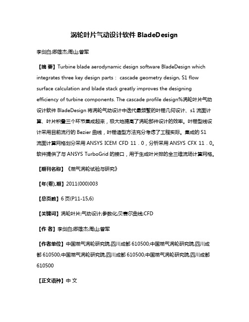
前身是BladeGen,ANSYS BladeModeler 强调了它在涡轮机械叶片设计领域的强大优势。
它能在短时间内设计出形状复杂的叶片,或对已有的叶片几何进行修改。
它内置各种工业常用的叶片模版,方便用户调用。
ANSYS BladeModeler 用户界面友好,整个过程自动化,叶片的三维视图,S1及S2流面图等多种视图完整而丰富。
ANSYS BladeModeler 还可以直接读入几何模型进行修改。
用户可以通过拖动流线上控制点等方式对叶片形状进行三维的方便修改,修改的结果立即直观地呈现在屏幕上。
ANSYS BladeModeler 生成的几何文件可以输出至流体和结构分析软件进行网格划分和数值计算。
特色功能
∙
将叶片设计专家丰富的设计分析经验融入友好的图形化界面 ∙
能直接创建新的叶片几何模型,也能对已有的模型进行修改 ∙
内置模版丰富,几乎可以设计所有的轴流,径流,混流式透平机械的静动叶片.前缘,尾缘,叶根叶尖间隙,大小叶片的处理都极为方便 ∙
各种叶片视图完整而丰富 ∙
压力面,吸力面的独立设计 ∙
子午流线的任意定义 ∙
前缘,尾缘的交互式改变 ∙
与CAD 软件及CFD 软件的良好接口实现了叶片设计,加工,分析一体化 ∙ 支持Workbench 集成
客户价值
∙
内置专家模版,对不同形状的叶片和通道都能快速生成 ∙
界面友好,过程简单流畅 ∙ 前后接口丰富稳定,用户不用放弃原来熟悉的工具
广州有道科技培训中心 h t t p ://w w w .020f e a .c o m。
基于ANSYSWorkbench增压器叶轮结构有限元分析
WLC- PNC@@SS/,/@-MHEV-Q G@HT/-DMG@@-D/-@D@-@CVM@PNC@TNA@C&#- MG/ITVT@C" XG@/PT@HH@CMGC@@2Q/P@-I/N-VHPNQ@H/I@IMVWH/IG@Q WE
ONH/QRNC.I) 9VI@Q N- MG@5jOjO RNC.W@-,G INSMAVC@QNC@I@VC,G NSMG@/PT@HH@CN- IMVM/,V-VHEI/IV-Q PNQVHV-VHEI/I&XGCNLDG IMVM/,V2
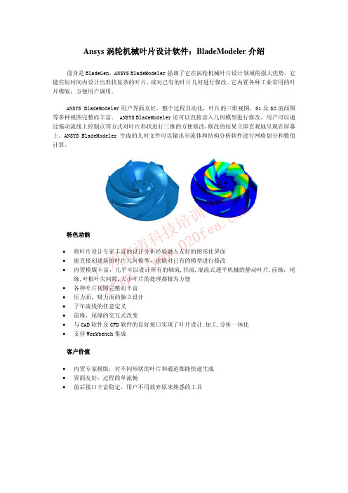
#叶轮有限元分析 $&$ 叶轮建立及网格划分 通过建模软件 ONH/QRNC.I建立叶轮三维实体模型)为避免 三维模型导入 5?OjO RNC.W@-,G 中网格划分失败"建叶轮实体 模型时对一些小特征' 如倒角"导圆( 进行简化处理)将模型保 存成 5?OjO RNC.W@-,G 可以识别的格式' IMT 格式( # 启动 5?OjOj RNC.W@-,G" 打 开 XNNH中 的 5-VHEI/IOEIM@P 中的 OMVM/,OMCL,MLCVH' 静力学分析模块( 模块中"导入三维实体 模型)添加材料库"添加 5HLP/-/LP5HHNE' 铝合金( )进行网格划 分"本次采用 X@MCVG@QCN-I法' 四面体法( 对叶轮进行网格划分" 网格尺寸选择 $PP"完成后用 5IT@,MdVM/N检查网格质量"结果 显示网 格 长 边 与 短 边 之 比 最 大 值 集 中 在 $&$1" 网 格 质 量 良好*(+ # 网格模型总共包含 $1J1(% 个节点"$%)13( 个单元# 网格 划分模型如图 $ 所示#
005_应用ANSYS WORKBENCH完成翼型叶片的设计及优化

应用ANSYS Workbench完成翼型叶片的设计及优化[李琼][华侨大学,361021][ 摘要] 本文介绍利用ANSYS Workben产品,对风扇叶片进行设计和效率优化,并分析其相比传统设计方法的优势。
该设计过程使用了该平台提供的Bladegen , Turbogrid, CFX, AnsysMechanical模块分别进行了叶片设计,网格划分,流体分析以及结构分析。
基于该平台的工具集成仿真环境,使得上述各个模块间的数据传递很容易实现;并且在任一数据被修改后,相应的模型和分析结果可以很方便地被更新,因而整个设计分析过程和传统方法相比极为简便,高效,并且能避免许多人为失误。
[ 关键词]叶片设计,空气动力学分析,流固耦合分析,效率优化Airfoil blade design with ANSYS Workbench[Qiong Li][Huaqiao University, 361021][ Abstract ] The process for airfoil blade design and efficiency optimization by using ANSYS Workbench is presented. Bladegen, Turbogrid, CFX and ANSYS mechanical are applied for blade shapedesign, meshing, aero dynamic analysis and structural analysis respectively. The designand optimization process is greatly simplified as well as the reliability is ensured with theadvantage of the workbench’s compatible simulation environment.[ Keyword ] aero dynamics, efficiency optimization, solid-fluid analysis1前言(背景介绍)为了降低使用成本,提高产品竞争力,风扇类产品的设计除了要使其满足特定工况,如流量,压升,强度等,还要通过优化使其效率最大化。
Ansys涡轮机械叶片设计软件:BladeModeler介绍
Ansys 涡轮机械叶片设计软件:BladeModeler 介绍
前身是BladeGen,ANSYS BladeModeler 强调了它在涡轮机械叶片设计领域的强大优势。
它能在短时间内设计出形状复杂的叶片,或对已有的叶片几何进行修改。
它内置各种工业常用的叶片模版,方便用户调用。
ANSYS BladeModeler 用户界面友好,整个过程自动化,叶片的三维视图,S1及S2流面图等多种视图完整而丰富。
ANSYS BladeModeler 还可以直接读入几何模型进行修改。
用户可以通过拖动流线上控制点等方式对叶片形状进行三维的方便修改,修改的结果立即直观地呈现在屏幕上。
ANSYS BladeModeler 生成的几何文件可以输出至流体和结构分析软件进行网格划分和数值计算。
特色功能
∙
将叶片设计专家丰富的设计分析经验融入友好的图形化界面 ∙
能直接创建新的叶片几何模型,也能对已有的模型进行修改 ∙
内置模版丰富,几乎可以设计所有的轴流,径流,混流式透平机械的静动叶片.前缘,尾缘,叶根叶尖间隙,大小叶片的处理都极为方便 ∙
各种叶片视图完整而丰富 ∙
压力面,吸力面的独立设计 ∙
子午流线的任意定义 ∙
前缘,尾缘的交互式改变 ∙
与CAD 软件及CFD 软件的良好接口实现了叶片设计,加工,分析一体化 ∙ 支持Workbench 集成
客户价值
∙
内置专家模版,对不同形状的叶片和通道都能快速生成 ∙
界面友好,过程简单流畅 ∙ 前后接口丰富稳定,用户不用放弃原来熟悉的工具
广州有道科技培训中心 h t t p ://w w w .020f e a .c o m。
基于ANSYS的某型航空发动机涡轮叶片的振动特性分析
基于ANSYS的某型航空发动机涡轮叶片的振动特性分析本文旨在对一款航空发动机的涡轮叶片进行振动特性分析,通过ANSYS软件进行模拟计算,以期评估其振动强度和工作寿命,为发动机设计提供参考。
1. 背景介绍与分析涡轮叶片作为航空发动机中的核心部件之一,其振动特性直接影响发动机的性能和寿命。
因此,在发动机设计中,对涡轮叶片的振动强度和稳定性进行分析和研究是至关重要的。
在本次分析中,我们将以某型航空发动机的涡轮叶片为例,通过ANSYS软件对其进行振动特性分析。
涡轮叶片的几何形状如图所示。
(图片)2. 建模与网格划分首先,在ANSYS中建立三维模型,采用SolidWorks导入到ANSYS平台。
接着,进行网格划分,采用四面体单元网格划分,设置裂纹控制等参数,进行网格剖分。
3. 材料选择与约束条件设置在建立模型和进行网格划分后,需要对涡轮叶片的材料进行选择,同时设定约束条件。
本次研究中,涡轮叶片的材料选用了镍基合金,其密度为8.28g/cm³,杨氏模量为210GPa,泊松比为0.3。
约束条件包括固定壳体支撑,在振动载荷下叶片不能有位移,不允许旋转。
4. 振动分析在进行建模、网格划分及设置约束条件之后,进入振动分析步骤。
本次分析采用动态分析法,采用隐式求解器求解其模态分析结果。
模态分析结果中包括杆件自然频率、振型形态和统计指标。
5. 计算结果与分析经过模拟计算,得出该涡轮叶片的前三阶固有频率为:335Hz、596Hz、916Hz。
下面就这些结果进行分析:1)自然频率随着振型的变化而变化。
而当达到某一频率时,就会发生共振现象,应引起足够的注意。
2)从涡轮叶片自然频率分析结果来看,其频率较高,工作在这样高的频率下容易导致疲劳断裂,从而出现永久性损坏,缩短了涡轮叶片的工作寿命,亦增加对机体的冲击力。
3) 在涡轮叶片的一些易损部位,比如根部区域,容易发生应力集中,导致应力低于叶片的材料极限从而使叶片疲劳失效。
旋转机械分析系统ANSYS TURBOSYSTEM
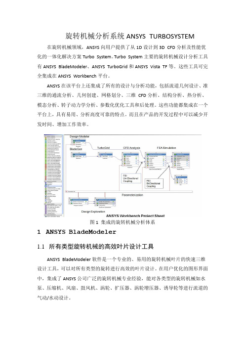
旋转机械分析系统ANSYS TURBOSYSTEM 在旋转机械领域,ANSYS向用户提供了从1D设计到3D CFD分析及性能优化的一体化解决方案Turbo System。
Turbo System主要的旋转机械设计分析工具有ANSYS BladeModeler、ANSYS TurboGrid和ANSYS Vista TF等。
这些工具可完全集成在ANSYS Workbench平台。
ANSYS在该平台上还集成了所有的设计与分析功能,包括流道几何设计、准三维的通流分析、几何创建、网格划分、三维CFD分析、结构分析、热分析、模态分析、转子动力学分析、参数化优化工具和后处理。
这些功能都集成在一个平台上,具有易用、分析高度可靠的特点。
而且在产品的开发过程中可以减少开发时间、增加工作效率。
图1 集成的旋转机械分析体系1ANSYS BladeModeler1.1所有类型旋转机械的高效叶片设计工具ANSYS BladeModeler软件是一个专业的、易用的旋转机械叶片的快速三维设计工具,可以对所有类型的旋转进行高效的叶片设计。
在用户优化的图形界面中,集成了ANSYS公司广泛的旋转机械专业经验,能对各类型的旋转机械如水泵、压缩机、风扇、鼓风机、涡轮、扩压器、涡轮增压器、诱导轮等进行流道的气动/水动设计。
1.2方便的模型导入功能ANSYS BladeModeler可方便地导入已有模型,为将来的模型细节设计、模拟及快速修改做好几何上的准备进。
图3 方便的模型导入功能1.3优秀的设计功能采用模板设计的方法ANSYS BladeModeler内置了六个模板设计工具,包括Radial Impeller、Simp le Axial、Radial Diffuser、Axial、Radial Deswirl Vane、Radial Turbine。
所有类型的旋转机械叶片设计都可以从中找到合适的设计模板。
图4 六种旋转机械设计模板采用Vista 1D设计的方法ANSYS BladeModeler的Vista 1D方法来自于老牌的工程咨询公司,英国PC A工程公司。
某离心叶轮叶片改型设计研究

10.16638/ki.1671-7988.2021.05.019某离心叶轮叶片改型设计研究*覃玄,朱涛(湖北汽车工业学院汽车工程学院,湖北十堰442002)摘要:该文以某高压比离心叶轮为研究对象,以改善叶轮流动特性和提升叶轮的气动性能为目标对其叶片进行改型设计。
文章基于ANSYS BladeGen,采用四阶Bezier曲线对叶轮叶顶弧线以及叶根弧线进行参数改变,通过流场数值模拟分析得到最终设计叶型。
数值模拟结果表明,新设计叶型离心叶轮相较于原叶轮压比提高了0.87%,效率提升了5.69%,达到了本次改型设计的目标。
关键词:离心叶轮;Bezier曲线;叶型设计中图分类号:U462 文献标识码:A 文章编号:1671-7988(2021)05-66-04Research on the Blade Modification Design of a Centrifugal Impeller*Qin Xuan, Zhu Tao( Hubei University of Automotive Engineering Department of Automotive Engineering, Hubei Shiyan 442002 )Abstract: This article is aimed to improve the flow characteristics and aerodynamic performance of a centrifugal impeller. Based on ANSYS BladeGen, by using four order Bezier curve the parameters of tip arc and the hub arc were changed, then the final blade was obtained through the numerical calculation of the flow field. The results show that, the newly designed centrifugal impeller has a 0.87% increase on the pressure ratio and a 5.69% increase on the efficiency, which also has achieved the goal of this article.Keywords: Centrifugal impeller; Bezier curve; Blade designCLC NO.: U462 Document Code: A Article ID: 1671-7988(2021)05-66-04引言压气机是废气涡轮增压器的重要组成部分,本文研究的离心叶轮则为压气机的核心部件[1]。
ANSYS有限元分析实用教程-叶轮,涡轮
Workshop Supplement
INTRODUCTION TO ANSYS 5.7 - Part 2
3.
进入前处理器,分别定义单元类型1为SOLID95, 单元类型2为MESH200.对MESH200单元 设置KEYOPY(1) = 5 :
– Main Menu > Preprocessor > Element Type > Add/Edit/Delete … [Add ...] – 选择 "Structural Solid" 和 "Brick 20node 95",然后按 [Apply] – 选择 "Not Solved" and "Mesh Facet 200",然后按[OK] 选择[Options ...] Set K1 = "TRIA 6-NODE",然后按[OK] [Close] 或使用命令: /PREP7 ET,1,SOLID95 ET,2,MESH200 KEYOPT,2,1,5
– – Main Menu > Preprocessor > Loads > -Loads- Apply > -Structural- Displacement > On Nodes + 或使用命令: D,ALL,UZ
January 30, 2001 Inventory #001444 W2-9
2A. 耦合
– – Main Menu > Preprocessor > MeshTool … 或使用命令: VMESH,1
Workshop Supplement
INTRODUCTION TO ANSYS 5.7 - Part 2
ANSYSfluent菜单中英文对照
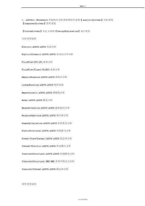
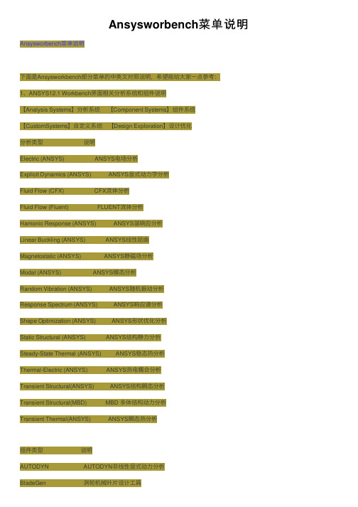
1、ANSYS12.1Workbench界面相关分析系统和组件说明【AnalysisSystems】分析系统【ComponentSystems】组件系统【CustomSystems】自定义系统【DesignExploration】设计优化分析类型说明Electric(ANSYS)ANSYS电场分析ExplicitDynamics(ANSYS)ANSYS显式动力学分析FluidFlow(CFX)CFX流体分析FluidFlow(Fluent)FLUENT流体分析HamonicResponse(ANSYS)ANSYS谐响应分析LinearBuckling(ANSYS)ANSYS线性屈曲Magnetostatic(ANSYS)ANSYS静磁场分析Modal(ANSYS)ANSYS模态分析RandomVibration(ANSYS)ANSYS随机振动分析ResponseSpectrum(ANSYS)ANSYS响应谱分析ShapeOptimization(ANSYS)ANSYS形状优化分析StaticStructural(ANSYS)ANSYS结构静力分析Steady-StateThermal(ANSYS)ANSYS稳态热分析Thermal-Electric(ANSYS)ANSYS热电耦合分析TransientStructural(ANSYS)ANSYS结构瞬态分析TransientStructural(MBD)MBD多体结构动力分析TransientThermal(ANSYS)ANSYS瞬态热分析组件类型说明AUTODYNAUTODYN非线性显式动力分析BladeGen涡轮机械叶片设计工具CFXCFX高端流体分析工具EngineeringData工程数据工具ExplicitDynamicLS-DYNALS-DYNA显式动力分析FiniteElementModelerFEM有限元模型工具FLUNETFLUNET流体分析Geometry几何建模工具MechanicalAPDL机械APDL命令MechanicalModel机械分析模型Mesh网格划分工具Results结果后处理工具TurboGrid涡轮叶栅通道网格生成工具VistaTF叶片二维性能评估工具2、主菜单【File】文件操作【View】窗口显示【Tools】提供工具【Units】单位制【Help】帮助信息3、基本工具条【New】新建文件【Open】打开文件【Save】保存文件【SaveAs】另存为文件【Import】导入模型【CompactMode】紧凑视图模式【ShadeExteriorandEdges】轮廓线显示【Wireframe】线框显示【Ruler】显示标尺【Legend】显示图例【Triad】显示坐标图示【ExpandAll】展开结构树【CollapseEnvironments】折叠结构树【CollapseModels】折叠结构树中的Models项【NamedSelections】命名工具条【UnitConversion】单位转换工具【MessagesMessages】信息窗口【SimulationWizard】向导【GraphicsAnnotations】注释【SectionPlanes】截面信息窗口【ResetLayout】重新安排界面4、建模【Geometry】几何模型【NewGeometry】新建几何模型【DetailsView】详细信息窗口【Graphics】图形窗口显示当前模型状态【Extrude】拉伸【Revolve】旋转【Sweep】扫掠【Skin/Loft】蒙皮【Thin/Surface】抽壳:【Thin】创建薄壁实体【Surface】创建简化壳【FacetoRemove】删除面所选面将从体中删除。
ansys中的bladegen涡轮叶片设计
ansys中的bladegen涡轮叶片设计首先在Workbench中选择Bladegen模块勾选创建轮毂和创建所有叶片选项选择径向叶轮标签,并输入Z值和R值(横轴为Z向,纵向为R)。
选择厚度/角度模式输入叶片包角140度,厚度值及叶片个数为7进入设计总窗口The most critical operation in the meridional view is to define the shapeof the hub and shroud curve. The endpoints for these curves werespecified when Initial Design Parameters were entered in the InitialMeridional configuration dialog.The hub and shroud profile for this case are well defined automatically.In this case, there is no need for any additional modificati**.意思是轮毂和轮缘(套罩)形状的定义在子午面上很关键,我们在前面初始化子午面结构参数已定义了这些曲线的终点。
它们的其它轮廓由系统自动生成,不需要修改。
用户可以通过改变坐标值及曲线特性进行修改。
双击各点修改坐标值来定义进口和出口截面1. Double click the shroud inlet point at the top left of themeridional view.2. The Point Location Dialog will open. The Horizontal value is the Axial location (Z co-ordinate) and the Vertical value represents the Radius.3. Enter -10 and 110 for the horizontal and vertical values. Click OK.4. Double click the hub inlet point (bottom left corner) and enter -10 and 25 for the horizontal and vertical values. Click OK.5. Double click the hub outlet point (top right corner) and enter 91 and 250 for the horizontal and vertical values. Click OK.6. Double click the shroud outlet point (top left corner) and enter 63 and 250 for the horizontal and vertical values. Click OK.查看叶片角度视图,默认激活层为hub layer,如图红点所示注意到纵坐标变化范围为140,即先前设置叶片包角值在角度视图右键选择调整叶片角度前缘尾缘Theta曲线自动转成带有六个控制点的Bezier segment同理进入shroud layer,修改角度定义叶片厚度轮廓,切换到hub layer定义三个点,并输入各厚度zoom to fit 调整视图显示通过五个点来调整抛物厚度曲线,再八个点来调整激活shroud layer,会发现厚度和hub layer是一样的选择叶片属性定义椭圆角生成模型,大功告成!!。
ANSYS CFX介绍.
ANSYS CFX介绍CFX是全球第一个通过ISO9001质量认证的大型商业CFD软件,是英国AEA Technology 公司为解决其在科技咨询服务中遇到的工业实际问题而开发,诞生在工业应用背景中的CFX一直将精确的计算结果、丰富的物理模型、强大的用户扩展性作为其发展的基本要求,并以其在这些方面的卓越成就,引领着CFD技术的不断发展。
目前,CFX已经遍及航空航天、旋转机械、能源、石油化工、机械制造、汽车、生物技术、水处理、火灾安全、冶金、环保等领域,为其在全球6000多个用户解决了大量的实际问题。
回顾CFX发展的重要里程,总是伴随着她对革命性的CFD新技术的研发和应用。
1995年,CFX收购了旋转机械领域著名的加拿大ASC公司,推出了专业的旋转机械设计与分析模块-CFX-Tascflow,CFX-Tascflow一直占据着90%以上的旋转机械CFD市场份额。
同年,CFX成功突破了CFD领域的在算法上的又一大技术障碍,推出了全隐式多网格耦合算法,该算法以其稳健的收敛性能和优异的运算速度,成为CFD技术发展的重要里程碑。
CFX一直和许多工业和大型研究项目保持着广泛的合作,这种合作确保了CFX能够紧密结合工业应用的需要,同时也使得CFX可以及时加入最先进的物理模型和数值算法。
作为CFX的前处理器,ICEM CFD优质的网格技术进一步确保CFX的模拟结果精确而可靠。
2003年,CFX加入了全球最大的CAE仿真软件ANSYS的大家庭中。
CFX 的用户将会得到包括从固体力学、流体力学、传热学、电学、磁学等在内的多物理场及多场耦合整体解决方案。
CFX将永远和我们的用户伙伴一起,用最先进的技术手段,不断揭开我们身边真实物理世界的神秘面纱。
一.CFX产品特点简介CFX是全球第一个在复杂几何、网格、求解这三个CFD传统瓶径问题上均获得重大突破的商业CFD软件。
借助于其独一无二的,有别于其它CFD软件的技术特点,CFX领导着新一代高性能CFD商业软件的整体发展趋势。
Ansysworbench菜单说明
Ansysworbench菜单说明Ansysworbench菜单说明下⾯是Ansysworkbench部分菜单的中英⽂对照说明,希望能给⼤家⼀点参考:1、ANSYS12.1 Workbench界⾯相关分析系统和组件说明【Analysis Systems】分析系统【Component Systems】组件系统【CustomSystems】⾃定义系统【Design Exploration】设计优化分析类型说明Electric (ANSYS) ANSYS电场分析Explicit Dynamics (ANSYS) ANSYS显式动⼒学分析Fluid Flow (CFX) CFX流体分析Fluid Flow (Fluent) FLUENT流体分析Hamonic Response (ANSYS) ANSYS谐响应分析Linear Buckling (ANSYS) ANSYS线性屈曲Magnetostatic (ANSYS) ANSYS静磁场分析Modal (ANSYS) ANSYS模态分析Random Vibration (ANSYS) ANSYS随机振动分析Response Spectrum (ANSYS) ANSYS响应谱分析Shape Optimization (ANSYS) ANSYS形状优化分析Static Structural (ANSYS) ANSYS结构静⼒分析Steady-State Thermal (ANSYS) ANSYS稳态热分析Thermal-Electric (ANSYS) ANSYS热电耦合分析Transient Structural(ANSYS) ANSYS结构瞬态分析Transient Structural(MBD) MBD 多体结构动⼒分析Transient Thermal(ANSYS) ANSYS瞬态热分析组件类型说明AUTODYN AUTODYN⾮线性显式动⼒分析BladeGen 涡轮机械叶⽚设计⼯具CFX CFX⾼端流体分析⼯具Engineering Data ⼯程数据⼯具Explicit Dynamic(LS-DYNA) LS-DYNA 显式动⼒分析Finite Element Modeler FEM有限元模型⼯具FLUNET FLUNET 流体分析Geometry ⼏何建模⼯具Mechanical APDL 机械APDL命令Mechanical Model 机械分析模型Mesh ⽹格划分⼯具Results 结果后处理⼯具TurboGrid 涡轮叶栅通道⽹格⽣成⼯具Vista TF 叶⽚⼆维性能评估⼯具2、主菜单【File】⽂件操作【View】窗⼝显⽰【Tools】提供⼯具【Units】单位制【Help】帮助信息3、基本⼯具条【New】新建⽂件【Open】打开⽂件【Save】保存⽂件【Save As】另存为⽂件【Import】导⼊模型【Compact Mode】紧凑视图模式【Shade Exterior and Edges】轮廓线显⽰【Wireframe】线框显⽰【Ruler】显⽰标尺【Legend】显⽰图例【Triad】显⽰坐标图⽰【Expand All】展开结构树【Collapse Environments】折叠结构树【Collapse Models】折叠结构树中的Models项【Named Selections】命名⼯具条【Unit Conversion】单位转换⼯具【Messages:Messages】信息窗⼝【Simulation Wizard】向导【Graphics Annotations】注释【Section Planes】截⾯信息窗⼝【Reset Layout】重新安排界⾯4、建模【Geometry】⼏何模型【New Geometry】新建⼏何模型【Details View】详细信息窗⼝【Graphics】图形窗⼝:显⽰当前模型状态【Extrude】拉伸【Revolve】旋转【Sweep】扫掠【Skin/Loft】蒙⽪【Thin/Surface】抽壳: 【Thin】创建薄壁实体【Surface】创建简化壳【Face to Remove】删除⾯:所选⾯将从体中删除。
ansys涡轮增压器设计
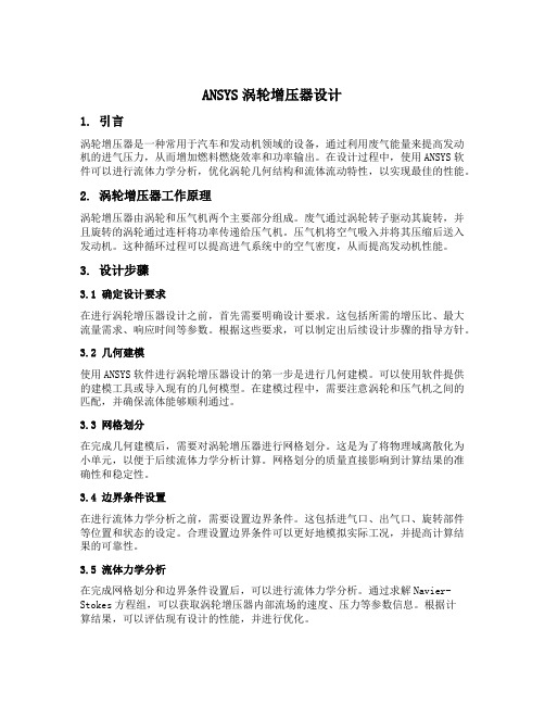
ANSYS涡轮增压器设计1. 引言涡轮增压器是一种常用于汽车和发动机领域的设备,通过利用废气能量来提高发动机的进气压力,从而增加燃料燃烧效率和功率输出。
在设计过程中,使用ANSYS软件可以进行流体力学分析,优化涡轮几何结构和流体流动特性,以实现最佳的性能。
2. 涡轮增压器工作原理涡轮增压器由涡轮和压气机两个主要部分组成。
废气通过涡轮转子驱动其旋转,并且旋转的涡轮通过连杆将功率传递给压气机。
压气机将空气吸入并将其压缩后送入发动机。
这种循环过程可以提高进气系统中的空气密度,从而提高发动机性能。
3. 设计步骤3.1 确定设计要求在进行涡轮增压器设计之前,首先需要明确设计要求。
这包括所需的增压比、最大流量需求、响应时间等参数。
根据这些要求,可以制定出后续设计步骤的指导方针。
3.2 几何建模使用ANSYS软件进行涡轮增压器设计的第一步是进行几何建模。
可以使用软件提供的建模工具或导入现有的几何模型。
在建模过程中,需要注意涡轮和压气机之间的匹配,并确保流体能够顺利通过。
3.3 网格划分在完成几何建模后,需要对涡轮增压器进行网格划分。
这是为了将物理域离散化为小单元,以便于后续流体力学分析计算。
网格划分的质量直接影响到计算结果的准确性和稳定性。
3.4 边界条件设置在进行流体力学分析之前,需要设置边界条件。
这包括进气口、出气口、旋转部件等位置和状态的设定。
合理设置边界条件可以更好地模拟实际工况,并提高计算结果的可靠性。
3.5 流体力学分析在完成网格划分和边界条件设置后,可以进行流体力学分析。
通过求解Navier-Stokes方程组,可以获取涡轮增压器内部流场的速度、压力等参数信息。
根据计算结果,可以评估现有设计的性能,并进行优化。
3.6 优化设计根据流体力学分析的结果,可以对涡轮增压器的几何结构进行优化。
这包括改变叶片形状、调整进出口尺寸等。
通过反复迭代优化,可以逐步提高涡轮增压器的性能。
4. 结果分析与评估在完成涡轮增压器设计和优化后,需要对结果进行分析和评估。
CFX涡轮增压器设计学习笔记 BM BladeGen BladeModer.
Anglபைடு நூலகம்/Thickness
Meridional View
Auxilliary View
Angle View
Thickness View
BladeGen 1.新建:Meridional View
• Curves can be defined as: 曲线可以被定义为:
• • • • • Piecewise Linear分段样条 Cubic Spline三次样条 Bezier贝塞尔曲线 Best Fit Polynomial最适合多项式 Arc Segment弧形段
叶片设计 角度/厚度 模型
叶片设计 压力/吸力模型
BladeGen 1.新建
选择压轮类型, 子午面主要参数 和叶型设计角度 /厚度还是压力/ 吸力模式。
BladeGen 1.新建:叶片初始化定义
• 可以定义包角、厚度、叶片数 量
•定义压 力面和 吸力面 主要参 数
BladeGen 1.新建:设计环境
谢谢观看
kevinwang1983@
Hub High Periodic Trailing Edge
坐标系
笛卡尔
子午面
叶面到叶片
坐标系
M versus R*Theta
坐标系
M-Prime versus Theta
坐标系
• The M-R coordinate system is useful for thickness specification since it is a dimensional view. M-R坐标系适合定义叶片厚度 • The M’- coordinate system is useful since it permits the designer to view the blade-to-blade surface in a plane where blade angles are preserved. M-R坐标系适合定义叶片角度。 • The blade profile can be defined using the Angle/Thickness Model or the Pressure/Suction Mode. 叶片轮廓可以定义使用角/厚度模型或压力面/吸力面模式
基于ANSYS的某涡喷发动机涡轮动频计算
基于ANSYS的某涡喷发动机涡轮动频计算ANSYS是一款常用的工业级三维有限元分析软件,可以用于许多不同领域的计算,特别是在航空航天领域中,其应用广泛。
在该领域中,涡喷发动机是现代飞机中常用的发动机类型之一,其结构复杂,计算难度大。
本文将介绍基于ANSYS的某涡喷发动机涡轮动频计算。
涡喷发动机是一种轴流涡扇发动机。
其由进气道、压气机、燃烧室、涡轮和尾喷管等组成。
其中涡轮是发动机的关键部件之一,其工作原理是通过燃气的高温高压冲击推动涡轮旋转,进而驱动压气机和涡扇运行。
然而,在燃气通过涡轮时,会发生诸如旋转失衡、共振、脱离等问题,这些问题会影响涡轮的性能和寿命。
因此,涡轮动频的计算对涡喷发动机的设计和优化非常重要。
涡轮动频的计算方法一般采用有限元方法。
有限元方法可以将结构分为若干小区域,通过数学算法求得每个小区域内的应力和应变情况,进而计算整个结构的力学特性。
在ANSYS中,我们可以采用有限元方法计算涡轮的模态分析(Modal Analysis)。
模态分析根据结构的弹性特性和材料特性计算出其固有频率及模态,并根据固有频率来判断结构的稳定性。
若结构的某一自由度频率与激励频率相等或近似相等,则会发生共振现象,从而使结构破坏或失效。
在ANSYS中,我们可以通过以下步骤计算涡轮动频。
首先,我们需要建立涡轮的三维模型。
其次,将该模型导入ANSYS中并设置材料属性、约束条件及加载条件。
然后,进行模态分析,计算出涡轮的固有频率和模态。
最后,根据计算结果判断涡轮是否存在动态失衡或共振问题,并结合实际工作情况对涡轮进行更合理的设计和优化。
总之,ANSYS作为一款强大的有限元分析软件,其在涡喷发动机涡轮动频计算方面有着广泛的应用。
通过用ANSYS计算涡轮的固有频率及模态,可以判断涡轮的稳定性,优化涡轮结构设计,提高涡喷发动机的性能和寿命。
涡喷发动机涡轮动频计算所需的相关数据包括涡轮的材料性质、涡轮的几何形状和尺寸、工作温度、转速等。
基于ANSYS软件的叶片轮盘的模态有限元分析报告
基于ANSYS软件的叶片轮盘的模态有限元分析报告一、概述本次大作业主要利用ANSYS软件对叶片轮盘的模态进行分析,计算出叶片轮盘的固有频率和振型。
然后与实际情况进行比较,证明分析的正确性,从而为叶片轮盘的优化分析提供了充分的理论依据,并且通过对ANSYS软件的实际操作深刻体会有限元分析方法的基本思想,对有限元分析方法的实际应用有一个大致的认识。
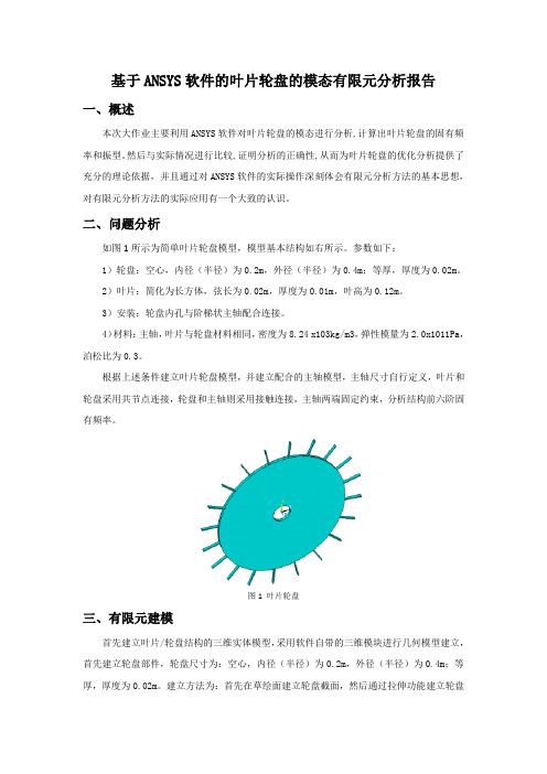
二、问题分析如图1所示为简单叶片轮盘模型,模型基本结构如右所示。
参数如下:1)轮盘:空心,内径(半径)为0.2m,外径(半径)为0.4m;等厚,厚度为0.02m。
2)叶片:简化为长方体,弦长为0.02m,厚度为0.01m,叶高为0.12m。
3)安装:轮盘内孔与阶梯状主轴配合连接。
4)材料:主轴,叶片与轮盘材料相同,密度为8.24 x10³kg/m3,弹性模量为2.0x1011Pa,泊松比为0.3。
根据上述条件建立叶片轮盘模型,并建立配合的主轴模型,主轴尺寸自行定义,叶片和轮盘采用共节点连接,轮盘和主轴则采用接触连接,主轴两端固定约束,分析结构前六阶固有频率。
图1 叶片轮盘三、有限元建模首先建立叶片/轮盘结构的三维实体模型,采用软件自带的三维模块进行几何模型建立,首先建立轮盘部件,轮盘尺寸为:空心,内径(半径)为0.2m,外径(半径)为0.4m;等厚,厚度为0.02m。
建立方法为:首先在草绘面建立轮盘截面,然后通过拉伸功能建立轮盘实体。
完成轮盘建模后,建立叶片部分,叶片尺寸为:简化为长方体,弦长为0.02m,厚度为0.01m,叶高为0.12m。
首先建立叶片截面,然后通过拉伸功能拉伸处单个叶片实体,最后通过环形阵列功能,阵列出18个叶片实体,最终几何模型如下图所示。
再进行主轴部件建立,首先在轮盘圆心位置建立直径为0.4m的草绘圆,并进行拉伸,采用两侧等向拉伸,分别拉伸1m,再做主轴两端分别建立直径为0.2m的草绘圆,并拉伸0.5m,形成阶梯轴,如下所示如图 2所示,采用材料默认的结构钢材料即可,材料的杨氏模量为2e11Pa,泊松比为0.3,密度7850kg/m3,所有部件材料为结构钢。
Bladegen学习资料
Bladegen学习资料[CFX/ICEMCFD]我是这样做Bladegen的,供初学者参考论坛中有很多人对Bladegen的应用感到兴趣,我也是一个初学者,有点体会也许对同是初学者的人们会有所帮助。
1. 在这里以轴流式转轮为例进行说明。
将已有的转轮2D图纸直接输入Bladegen是不可能的。
首先必须把2D图建成3D实体。
在该流体域中通过投影和面之间的相交获取一些曲线的igs文件。
他们是:1. 叶片最外缘型线投影到轮缘(Shroud)曲面上的封闭曲线。
如果由多根曲线组合而成,应拟合成一根曲线。
命名为shroud_curve.igs。
2. 叶片最内侧型线投影到轮轂(Hub)曲面上的封闭曲线。
命名为hub_curve.igs。
3. 在轮轂与轮缘曲线之间,绘制数条流线(本例中选用两条),并分别旋转成两个曲面。
然后用两曲面相交的方法分别求出两条与叶片表面相交曲线。
分别称为curve2.igs 和curve3.igs。
如果这些相交曲线分别由多个线段组成,则将他们分别拟合成单一曲线。
4. 叶片最外缘型线的骨线投影到轮缘(Shroud)曲面上的流线状曲线,称为shroud_curve.igs。
5. 叶片最内侧型线的骨线投影到轮轂(Hub)曲面上的流线状曲线,称为hub_curve.igs。
至此,有了这四条封闭曲线和两条开敞流线状曲线,进入Bladegen的条件已具备。
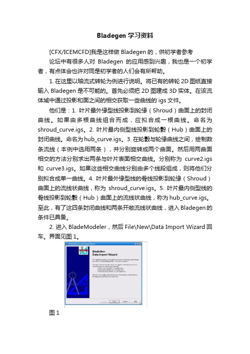
2. 进入BladeModeler,然后File\New\Data Import Wizard回车。
界面见图1。
图13. 两次Next后,进入如图2所示界面。
选第一选项(图中红圈)后Next。
图24. 点击Next直到出现图3所示界面。
用图中Add File按键相继输入六条igs曲线。
图35. 先点击右侧清单第二步中的Select Hub Curve,再在图形界面中点击相对应的曲线,被点中的曲线变为红色。
用同样的方法处理Shroud Curve。
- 1、下载文档前请自行甄别文档内容的完整性,平台不提供额外的编辑、内容补充、找答案等附加服务。
- 2、"仅部分预览"的文档,不可在线预览部分如存在完整性等问题,可反馈申请退款(可完整预览的文档不适用该条件!)。
- 3、如文档侵犯您的权益,请联系客服反馈,我们会尽快为您处理(人工客服工作时间:9:00-18:30)。
首先在Workbench中选择Bladegen模块
勾选创建轮毂和创建所有叶片选项
选择径向叶轮标签,并输入Z值和R值(横轴为Z向,纵向为R)。
选择厚度/角度模式
输入叶片包角140度,厚度值及叶片个数为7
进入设计总窗口
The most critical operation in the meridional view is to define the shape
of the hub and shroud curve. The endpoints for these curves were
specified when Initial Design Parameters were entered in the Initial
Meridional configuration dialog.
The hub and shroud profile for this case are well defined automatically.
In this case, there is no need for any additional modificati**.
意思是轮毂和轮缘(套罩)形状的定义在子午面上很关键,我们在
前面初始化子午面结构参数已定义了这些曲线的终点。
它们的其它轮廓由系统自动生成,不需要修改。
用户可以通过改变坐标值及曲线特性进行修改。
双击各点修改坐标值来定义进口和出口截面
1. Double click the shroud inlet point at the top left of the meridional view.
2. The Point Location Dialog will open. The Horizontal value is the Axial location (Z co-ordinate) and the Vertical value represents the Radius.
3. Enter -10 and 110 for the horizontal and vertical values. Click OK.
4. Double click the hub inlet point (bottom left corner) and enter -10 and 25 for the horizontal and vertical values. Click OK.
5. Double click the hub outlet point (top right corner) and enter 91 and 250 for the horizontal and vertical values. Click OK.
6. Double click the shroud outlet point (top left corner) and enter 63 and 250 for the horizontal and vertical values. Click OK.
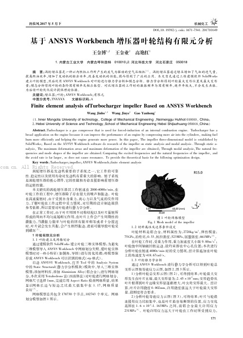
查看叶片角度视图,默认激活层为hub layer,如图红点所示注意到纵坐标变化范围为140,即先前设置叶片包角值
在角度视图右键选择调整叶片角度
前缘
尾缘
Theta曲线自动转成带有六个控制点的Bezier segment
同理进入shroud layer,修改角度
定义叶片厚度轮廓,切换到hub layer
定义三个点,并输入各厚度
zoom to fit 调整视图显示
通过五个点来调整抛物厚度曲线,再八个点来调整
激活shroud layer,会发现厚度和hub layer是一样的选择叶片属性定义椭圆角
生成模型,大功告成!!。