AM335x uboot spl分析
AM335x学习记录

AM335x 学习笔记1 硬件及其开发环境篇1.1 开发环境的搭建1.1.1 路由器方式的 NFS 启动1) 通过路由器的方式来启动 NFS 文件系统 设置路由器局域网的网关:192.168.1.1,然后将开发板和 PC 都连接在路由器的 LAN 端口,并且采用 DCHP 的 方式来实现 tftp 和 nfs。
2) uEnv.txtserverip=192.168.1.27 rootpath=/opt/ti-sdk-am335x-evm/targetNFS bootfile=uImage-am335x-evm.bin ip_method=dhcp tftp_nfs_boot=echo Booting from network...; dhcp ${loadaddr} ${bootfile}; run net_args; bootm ${loadaddr} uenvcmd=run tftp_nfs_boot1.1.2 Root 用户登陆#sudo passwd root #****** #****** #sudo –s –H 切换到 root 用户 然后就可以重启虚拟机,以用户 root 来登陆1.1.3 中文字库问题#locale –a 查看 是否有 zh_CN,zh_CN.gb18030,zh_CN.gb2312 等 #vim /var/lib/locales/supported.d/local#dpkg-reconfigure locales #locale-gen zh_CN.GB18030 #locale-gen zh_CN.GB2312 #locale-gen zh_CN.GBK1.1.4 环境变量设置路径#vim /etc/envinoment 常用的 3 个永久设置路径 #vim /etc/envirnoment #vim /etc/profile #vim ~/.bashrc (/root/.bashrc)1.1.5 设置 ubuntu 的上网 ip设置为 bridge 连接方式,设定静态 IP 地址.1.1.6 更改 sh 工具#rm /bin/sh # ln –s /bin/bash /bin/sh #apt-get install fakeroot1.1.7 安装必须的工具#apt-get install vim #apt-get install build-essential #apt-get install libtool #apt-get install bsion(干什么用的还不清楚) GNU autotools 主要包括三个工具 autoconf, automake,libtool1.1.8 虚拟机开发工具的安装$ sudo apt-get install build-essential libncurses-dev flex bison autoconf automake libmpfr-dev texinfo nfs-kernel-server tftpd-hpa libcloog-ppl1.2 AM335x BeagleBone 的 NFS 启动Sd 卡的识别:在/media/下面显示内容 在/dev/sd* 下显示分区 卸载:#unmount /dev/sdb1 这个是在 AM335X-LINUX-PSP-04.06.00.03 里面找的 1) 制作 sd 启动盘 MLO+uboot.img+uImage+rootfs#!/bin/bash if [[ -z $1 || -z $2 || -z $3 || -z $4 ]] then echo "mksd-am335x Usage:" echo " echo " exit fi if ! [[ -e $2 ]] then echo "Incorrect MLO location!" exit fi if ! [[ -e $3 ]] then echo "Incorrect u-boot.img location!" exit fi if ! [[ -e $4 ]] then echo "Incorrect uImage location!" exit fi if ! [[ -e $5 ]] then echo "Incorrect rootfs location!" exit fi echo "All data on "$1" now will be destroyed! Continue? [y/n]" read ans if ! [ $ans == 'y' ] then exit fi echo "[Partitioning $1...]" DRIVE=$1 dd if=/dev/zero of=$DRIVE bs=1024 count=1024 SIZE=`fdisk -l $DRIVE | grep Disk | awk '{print $5}'` echo DISK SIZE - $SIZE bytes CYLINDERS=`echo $SIZE/255/63/512 | bc` echo CYLINDERS - $CYLINDERS mksd-am335x <device> <MLO> <u-boot.img> <uImage> <rootfs tar.gz >" Example: mksd-am335x /dev/sdc MLO u-boot.img uImage nfs.tar.gz"{ echo ,9,0x0C,* echo ,,,} | sfdisk -D -H 255 -S 63 -C $CYLINDERS $DRIVE echo "[Making filesystems...]" mkfs.vfat -F 32 -n boot "$1"1 &> /dev/null mkfs.ext3 -L rootfs "$1"2 &> /dev/null echo "[Copying files...]" mount "$1"1 /mnt cp $2 /mnt/MLO cp $3 /mnt/u-boot.img cp $4 /mnt/uImage umount "$1"1 mount "$1"2 /mnt tar zxvf $5 -C /mnt &> /dev/null chmod 755 /mnt umount "$1"2 echo "[Done]"2) 建立 uEnv.txt (我是将 tf 卡放入读卡器,在虚拟机下面 vim 编写的。
基于AM335x的U-Boot-SPL 的CCS 调试

基于AM335x的U-Boot/SPL 的CCS 调试在基于Linux的AM335x软件开发流程中,第一步就是U-Boot/SPL(SecondProgram Loader)的移植。
在移植中遇到问题比较常见,而U-Boot/SPL的调试手段比较简陋,不便于迅速找到问题。
利用仿真器可以单步调试的特点,就可以迅速定位到出问题的代码所在位置,加速移植的调试过程。
本文主要介绍如何用CCS+emulator调试基于AM335x的U-Boot/SPL。
1. AM335x Linux启动过程以及U-Boot/SPL调试代码的准备1.1 [url=]AM335x Linux[/url]的启动过程AM335x Linux的启动主要包括ROM,SPL,U-Boot 和kernel四个启动步骤:A. ROM codeROM code是固化在芯片内部的代码,当上电时序正确,而且晶振等芯片启动所需的条件都具备时,AM335x 会从ROM code开始运行。
ROM code首先会读取sys_boot引脚上的配置,以确定存放SPL的存储器,或者可以获取SPL的外设。
具体可以参考AM335x technical reference manual中的第26章Initialization。
ROM code会从相应的地方读取/获取SPL,并运行SPL。
B. SPLSPL和U-Boot 是bootloader的两个阶段。
这里分为两个阶段的原因是,ROM code中不会配置DDR,时钟等最小系统,所以ROM code只能把bootloader加载到片上SRAM中,而片上SRAM对成本影响很大,所以通常很小,例如在AM335x上只有64K,不足够放下整个U-Boot,所以将U-Boot分成两部分,SPL 和U-Boot。
SPL主要的职责就是初始化DDR,时钟等最小系统,以读取U-Boot,并加载到DDR中。
具体来看,SPL 由ROM code加载到片上SRAM的起始位置,也就是0x402F0400。
AM335x的网口启动及Flash烧写用户指南

AM335x的网口启动及Flash烧写用户指南概述:鉴于AM335x可以通过网口启动的方式将MLO,u-boot.img,kernel通过TFTP的方式下载至开发板,并可通过NFS的方式完成文件系统的挂载,因此,对最小系统板而言,仅需网口便可完成整个Linux的启动。
本文基于网口的启动方式,对网口启动的操作流程进行描述,并着重介绍了如何使用网口启动方式进行flash的烧写。
由于使用该方式进行flash烧写的操作是在UBoot环境中以脚本的方式实现,因此,用户可自定义具体的操作流程,灵活性较好。
PC环境:主机: Windows 7虚拟机: Virtual Box(version 4.1.12), Ubuntu 10.04.Linux SDK版本: 06.00.00.00AM335x开发板平台:GPEVM.网口启动配置流程:1.在Ubuntu中安装TFTP服务和NFS服务,确保可以正常TFTP download和挂载NFS。
(网上关于如何TFTP kernel以及挂载NFS的资料较多,因此,本文主要针对MLO(SPL)和u-boot阶段的设计进行描述,对kernel和NFS的加载操作将不再赘述)。
本示例中,TFTP目录为”/tftpboot”,NFS目录为”/nfs_share”。
2.在Ubuntu中进行DHCP服务的安装和配置:本示例中,通过以下步骤将本机建成主机IP为192.168.1.1的服务器,地址空间为192.168.1.100至192.168.1.199。
a.使用root账户登录Ubuntu,使用该命令进行DHCP服务的安装:apt-get install dhcp3-server(本文中粗斜体为命令行输入内容,下同)b.增加dhcp服务的网卡端口(本例中使用的网口为eth0)。
安装完成后,进入/etc/default目录,修改dhcp3-server文件:i.vim /etc/default/dhcp3-serverii.在INTERFACES=””的参数中增加eth0iii.保存后退出.c.增加地址空间定义。
AM335x Flash Tool -- UniFlash 烧写工具使用简介及问题解决方案汇总
AM335x Flash Tool -- UniFlash 烧写工具使用简介及问题解决方案汇总大家好,目前很多人都在关注AM335x flash tool(UniFlash)的进展情况,这篇文章会对当前的进展情况进行汇总,并就客户使用过程中遇到的一些问题,给出了相应的解决方案。
目前的UniFlash官方发布的版本中,仅支持NAND FLASH的烧录,近期版本中将会更新对eMMC烧录功能的支持。
UniFlash的下载地址:/index.php/NowFlash%E2%84%A2_Programming_ToolUniFlash的主机端安装用户指南:/index.php/Sitara_Uniflash_Quick_Start_GuideUniFlash的image编译,脚本编译使用指南(Linux环境下):/index.php/Sitara_Linux_AM335x_Flash_Programming_Linux_Developmen t使用注意事项及问答:1.使用该Uniflash进行NAND FLASH烧写时,Uniflash会先将u-boot-spl-restore.bin和u-boot-restore.img下载到开发板中,启动开发板进入到UBOOT阶段,从而调用脚本文件进行FLASH的烧写,所以需要先对SDK6.0开发包进行UBOOT的移植。
移植时,一定要加入UBOOT 的patch:/index.php/Sitara_Linux_AM335x_Flash_Programming_Linux_Dev elopment#Build_SPL_.28MLO.29_and_U-Boot_for_Flashing2.请注意,制作用于NAND flash烧写的启动image时,确认使用的编译选项为:am335x_evm_restore_flash_usbspl3.在Uniflash进行u-boot-spl-restore.bin的下载时,如果出现usb网络反应超时,请确认是否已经安装我们的usb patch:0001-u-boot-Change-default-cdc_connect_timeout-to-15s.patch。
关于AM335系列的板卡和相关模块产品常见问题
关于AM335系列的板卡和相关模块产品常见问题最近有客户在使用OK335x系列开发板中遇到了一些问题,所以在这里简单地总结了几点常见问题和解决方案,在这里分享一下。
如果您手中正好有飞凌的AM335x系列板卡,请仔细阅读,可能目前困扰您的问题答案就在这里!一.关于OK335x系列开发板,启动时,调试串口循环打印CCCCC问题分析以下为打印信息:建议从两方面进行问题排查:(1)OK335x系列开发板启动方式有2种:SD卡、nand. 请检查是否设置的SD卡启动,但是没有插SD卡或者SD卡中无程序。
底板上的拨码开关要拨到相应位置,参考以下说明:1. SD 卡启动设置:直接拨到 On2. NandFlash 启动设置:直接拨到 Off注:On 代表拨到上方,Off 代表拨到下方(2)飞凌OK335x系列开发板DI8-13的引脚,是boot启动项相关引脚。
如果您这几个引脚上接的外设模块电平跟uboot(下拉)启动电平相反,也可能会影响启动。
可以排查下是否是这几个引脚导致。
(3)如果排查以上两点还未解决问题,请联系飞凌技术支持************!二.关于OK335x系列开发板启动时,串口打印信息出现:please contact forlinx问题分析。
以下为打印信息:建议从两方面进行问题排查:(1)FET335x系列核心板上有个加密芯片:DS2406,通过IIC 接的CPU,这个芯片用户不能使用,因为出厂时里面已经写入了飞凌的加密信息,只有飞凌系统可以使用。
uboot在启动过程中会取读取保存在DS2460里的密码。
验证不通过的时候,会在串口打印信息里提示“Contact Forlinx….”,这种情况一般是加密芯片里的密码丢了,也可能是出厂没有烧写加密芯片。
(2)除了加密芯片用了一路IIC接口,核心板还支持2路,有些用户需要接自己的IIC外设模块。
如果您把设备挂载到加密芯片的这路IIC上,地址出现冲突,这样也可能会有影响,出现“please contact forlinx”信息。
U-boot中SPL功能和源码流程分析

U-boot中SPL功能和源码流程分析 在U-boot⽬录下,有个⽐较重要的⽬录就是SPL的,SPL到底是什么呢?为什么要⽤它呢? SPL(Secondary programloader)是uboot第⼀阶段执⾏的代码。
主要负责搬移uboot第⼆阶段的代码到系统内存(System Ram,也叫⽚外内存)中运⾏。
SPL是由固化在芯⽚内部的ROM引导的。
我们知道很多芯⽚⼚商固化的ROM⽀持从nandflash、SDCARD等外部介质启动。
所谓启动,就是从这些外部介质中搬移⼀段固定⼤⼩(4K/8K/16K等)的代码到内部RAM中运⾏。
这⾥搬移的就是SPL。
在最新版本的uboot中,可以看到SPL也⽀持nandflash,SDCARD等多种启动⽅式。
当SPL本⾝被搬移到内部RAM中运⾏时,它会从nandflash、SDCARD等外部介质中搬移uboot第⼆阶段的代码到系统内存中。
SPL复⽤的是uboot⾥⾯的代码. SPL的主要功能就是衔接系统的硬件SRAM和u-boot之间的纽带。
1.BasicArm Initialization2.UART console initialization3.Clocks and DPLL Locking(minimal)4.SDRAM initialization5.Mux(minimal)6.Boot Device Initialization, based on where we are booting from MMC1, or MMC2,or Nand, or Onenand7.Bootloading real u-boot from the Boot Device and passing control to it. 怎么编译SPL呢? 上⽂中说道“SPL复⽤的是uboot⾥⾯的代码”,那要⽣成我们所需要的SPL⽬标⽂件,我们⼜该如何下⼿呢?很容易想到,通过编译选项便可以将SPL和uboot代码分离、复⽤。
AM335x UBOOT移植记录

board_init_r 第 2 阶段的初始化,在 board.c 文件中
enable_caches 这个函数没有做什么内容
board_init
第 2 次初始化平台,这里可以初始化其他内容了,和平台相关
mem_malloc_init 初始化 malloc 内存
nanபைடு நூலகம்_init
初始化 NAND(CONFIG_CMD_NAND 需要定义)
uboot 的代码运行流程 u-boot-2011.09-psp04.06.00.08/arch/arm/cpu/armv7 start.s 入口运行文件
bl save_boot_params 跳转到 lowlevel_init.S 该 文 件 在 (arch\arm\cpu\armv7\omap-common) , 如 果 是 MLO 则 会 定 义
1、.boards.depend 2、include/config.h
/* Automatically generated - do not edit */ #define CONFIG_BOARDDIR board/ti/am335x #include <config_cmd_defaults.h> #include <config_defaults.h> #include <configs/am335x_evm.h> #include <asm/config.h> 3、include/config.mk ARCH = arm CPU = armv7 BOARD = am335x VENDOR = ti SOC = ti81xx
这个目录下的几个文件,start.s 这个是程序的入口执行文件 u-boot-2011.09-psp04.06.00.08/arch/arm/cpu/armv7/omap-common u-boot-2011.09-psp04.06.00.08/arch/arm/cpu/armv7/ti81xx
飞凌AM335x开发板Linux用户手册

飞凌AM335x开发板Linux用户手册OK335X-Linux用户手册第一章OK335X简介OK335X开发板基于TI AM335X处理器,运行主频最高720M,支持Linux,WinCE,Android三大操作系统,可用于工业产品设计。
OK335X有核心板和底板组成,核心板主要芯片有:CPU,NandFlash,Memory,PowerManage。
使用我们的核心板,只需要根据您的业务需求开发自己的底板,这样可加速您的产品上市时间,让您从平台搭建的复杂环境中脱离。
下面我们具体描述OK335X核心板和底板资源。
OK335X产品图片如下所示:核心板硬件资源:1CPU主频:720M(支持AM3352,AM3354,AM3356,AM3357,AM3358,AM3359)2NandFlash:256M(Micro SLC)3Memory:265M(Micro DDR2)4PowerManage IC:TPS65217B(TI AM335X专用电源IC)底板资源:14路串口(2个232电平,2个TTL电平,232电平已经使用DB9座子引出,其中COM0作为调试串口使用,注意:OK335X-V1底板中UART4暂时不能使用,下一硬件版本将修正这个问题)。
21路100M网口3音频接口(1路Phone输出,1路Line-in输入)41个SD卡接口56个用户按键63路I2C接口71个LCD接口(支持RGB888模式,支持电阻触摸和电容触摸。
默认标配7寸电阻屏)81路PWM接口,用于蜂鸣器测试。
91路Can接口101路SDIO接口11多路用户IO接口12四路USB2.0接口,一路USB2.0OTG(目前板子为一路USB Host接口,后续会增加到四路USB HUB)131路SPI接口148路AD(其中4路用于电阻触摸,1路用于滑动变阻器AD测试,其余3路通过插针引出,另外滑动变阻器端有跳线设置,通过跳线可以设置这路AD用于插针引出,还是用于可调电阻测试)15引出总线接口(缺省未焊接底座)161个RESET按钮,用于系统复位。
MYD-AM335X-J Linux 开发手册说明书

MYD-AM335X-J Linux 开发手册版本V1.12014/10/23版本记录目录第1章概述及软件资源介绍 (1)1.1 概述 (1)1.2 软件资源 (1)第2章Linux开发环境搭建 (3)2.1 建立工作目录 (3)2.2 设置交叉编译工具 (3)2.3 安装工具 (3)第3章Linux系统编译 (4)3.1 编译Bootloader (4)3.2 编译Linux内核 (5)3.3 制作文件系统 (5)第4章Linux 系统烧写 (6)4.1 TF卡系统映像更新 (6)4.2 NAND Flash更新/恢复 (7)第5章Linux应用程序 (10)5.1 GPIO (10)5.2 NET (10)5.3 RTC (11)5.4 LCD (11)5.5 Audio (12)5.6 I2C总线测试 (12)5.7 串口 (12)5.8 RS485 (12)5.9 CAN (13)5.10 引脚功能切换 (13)5.10.1 RS485_1跟UART5_RTSCTS 切换145.10.2 RS485_2和UART3切换及CAN1和UART4切换15第6章Qt开发 (17)6.1 使用光盘提供的Qt SDK (17)6.2 交叉编译Qt开发环境 (17)6.3 移植Qt到开发板 (18)6.4 交叉编译Qt应用程序 (19)第1章概述及软件资源介绍1.1 概述MYD-AM335X-J提供了丰富的系统资源和软件资源,本手册将从环境搭建开始,一步步介绍如何进行MYD-AM335X-J Linux开发。
本手册中开发主机上的命令以Ubuntu为例进行教授。
1.2 软件资源表1-1第2章Linux开发环境搭建2.1 建立工作目录拷贝MYD-AM335X-J光盘中的资料到主机中:$ mkdir -p <WORKDIR>$ cp -a <DVDROM>/05-Linux_Source/* <WORKDIR>2.2 设置交叉编译工具$ cd <WORKDIR>/Toolchain$ tar -xvjf \gcc-linaro-arm-linux-gnueabihf-4.7-2013.03-20130313_linux.tar.bz2$ export PATH=$PATH:<WORKDIR>/Toolchain/\gcc-linaro-arm-linux-gnueabihf-4.7-2013.03-20130313_linux/bin$ export CROSS_COMPILE=arm-linux-gnueabihf-执行完“export”命令后输入arm按Tab键来检查是否设置成功,该设置只对当前终端有效,如需永久修改,请修改用户配置文件。
AM335x U-Boot User's Guide中文手册
AM335x U-Boot User's Guide /****************************************************************** * author: 卢浩* time: 2012.09.12* environment: ubuntu10.04LTS +TI AM3359* kernel version: linux-3.2* Official Website: * QQ Group For Technology Exchange:122879839******************************************************************/ 风核科技出品—AM3359系列搭建uboot开发环境进入官方提供的SDK包的uboot目录$ cd ./AM335x-LINUX-PSP-MM.mm.pp.bb/src/u-boot/u-boot-MM.mm.pp.bb编译口令$ [ -d ./am335x ] && rm -rf ./am335x$ make O=am335x CROSS_COMPILE=arm-arago-linux-gnueabi- ARCH=arm am335x_evm编译完成将会生成可执行性文件MLO和u-boot.img。
主机配置:用串口线把主机和EVM板连接起来,设置超级终端参数如下:*Baud rate: 115,200*Data bits: 8*Parity: None*Stop bits: 1*Flow control: None开发板配置:设置启动方式:请注意,红色位置为off,绿色位置为on Nand启动,请设置拨码开关如下:SPI启动,请设置拨码开关如下:UART启动,请设置拨码开关如下:SD启动,请设置拨码开关如下:CPSW启动,请设置拨码开关如下:注意,从CPSW启动这样设置是因为EVM板用的是RGMII mode。
am335xu-boot启动过程分析

am335xu-boot启动过程分析 u-boot属于两阶段的bootloader,第⼀阶段的⽂件为 arch/arm/cpu/armv7/start.S 和 arch/arm/cpu/armv7/lowlevel_init.S,前者是平台相关的,后者是开发板相关的。
1. u-boot第⼀阶段代码分析 (1)硬件设备初始化 将CPU的⼯作模式设为管理模式(SVC); 关闭中断; 禁⽤MMU,TLB ; 板级初始化; (2)为加载Bootloader的第⼆阶段代码准备RAM空间 加载u-boot.img,跳转到u-boot.img; 上述⼯作,也就是uboot-spl代码流程的核⼼。
代码如下:arch/arm/cpu/armv7/start.S1/*2 * the actual reset code3*/4reset:5 bl save_boot_params6/*7 * disable interrupts (FIQ and IRQ), also set the cpu to SVC32 mode,8 * except if in HYP mode already9*/10 mrs r0, cpsr11 and r1, r0, #0x1f @ mask mode bits12 teq r1, #0x1a @ test for HYP mode13 bicne r0, r0, #0x1f @ clear all mode bits14 orrne r0, r0, #0x13 @ set SVC mode15 orr r0, r0, #0xc0 @ disable FIQ and IRQ16 msr cpsr,r017@@ 以上通过设置CPSR寄存器⾥设置CPU为SVC模式,禁⽌中断18@@ 具体操作可以参考《[kernel 启动流程] (第⼆章)第⼀阶段之——设置SVC、关闭中断》的分析1920/* the mask ROM code should have PLL and others stable */21#ifndef CONFIG_SKIP_LOWLEVEL_INIT22 bl cpu_init_cp1523@@ 调⽤cpu_init_cp15,初始化协处理器CP15,从⽽禁⽤MMU和TLB。
AM335X开发日记

AM335X平台开发日记2014-11-24至2014-11-29进行核心板原理图设计2014-12-1至2014-12-10进行PCB设计。
2014-12-5开始学习AM335X软件部分的知识。
安装了vmware虚拟机,10.0.1版本的。
安装了ubunt12.04版本。
安装vmware-tools,创建共享文件夹。
在root(需执行sudo su)下执行mount -t vmhgfs .host:/ /mnt/hgfs在windows共享文件夹存放TI安装包ti-sdk-am335x-evm-06.00.00.00-Linux-x86-Install.bin。
在终端里面执行安装。
安装目录为/usr/local/ti-sdk-am335x-evm#,一般会自动加入环境变量,如果没有,在/etc/environment增加环境变量:(注意:6.0的安装包不支持ubunt14.04版本,只支持12.04以下的版本)PATH="/usr/local/sbin:/usr/local/bin:/usr/sbin:/usr/bin:/sbin:/bin:/usr/games:/usr/local /ti-sdk-am335x-evm/linux-devkit/sysroots/i686-arago-linux/usr/bin:"输入命令arm-linux-gnueabihf-gcc –v即可查询版本执行setup.sh配置linux环境,例如安装包更新,NFS,TFTP,minicom等。
下载了Uniflash V3,准备选择USB或者ETH接口进行FLASH编程。
执行命令make CROSS_COMPILE=arm-linux-gnueabihf- O=am335x ARCH=arm am335x_evm编译u-boot,生成MLO(spl)和u-boot.imgNandflash程序分区:1.0-0x1ffff 为SPL2.0x20000-0x3ffff为SPL backup13.0x40000-0x5ffff为SPL backup24.0x60000-0x7ffff为SPL backup35.0x80000-0x25ffff为uboot6.0x260000 -0x27ffff为env7.0x280000-0x77ffff为linux kernel8.0x780000- 为file system9.下载uboot软件并进行修改适应新设计的核心板,并把uboot下载到板子里调试运行。
335X uboot备份kernel

Uboot备份kernel代码解析添加功能原因:nand储存引导代码的时候,不知道什么原因引起的,会出现随即的一个位取反,从而不能正常启动。
添加思路:此次添加一共备份了3份内核,在引导第一份内核的时候,如果出现某一个位错误标记出错的位置,将读取备份的page存入RAM中,如果第二份在page还有错误,将读取第三份。
这样可以大大降低不能正常启动带来的问题。
添加代码在drivers/mtd/nand/nand_base.c代码分析;/*******************/#define KERNEL_BACKUP_PAGE_NUM 0x500 启动代码第1份的地址0x500*0x800=0x280000#define KERNEL_BACKUP_1_PAGE_NUM 0x3e700 启动代码第2份的地址0x3e700*0x800=0x1f380000#define KERNEL_BACKUP_2_PAGE_NUM 0x3f100 启动代码第3份的地址0x3f100*0x800=0x1f880000#define KERNEL_SIZE 0xa00 (页数)(0xa00*0x800=5M)#define KERNEL_SIZE 0x800 (页数)(0x800*0x800=4M)每份内核的大小int TEST;测试用的static int ecc_b; 计算校验和static int ecc_sum; 计算校验和static int page_sum_err; 标记变量,出现错误的时候不为0 static int page_mark; 按照页存入oob区static unsigned int READ_KERNEL; 读kernel的标记static unsigned int WRITE_KERNEL; 写kernel的标记/*******************/此部分是在写入的时候,添加页码和校验存入OOB区的后6个字节,58-60是存放page码数,61-63是存放校验和。
AM335x_Boot_From_SPI_Flash__Jffs2_FS_
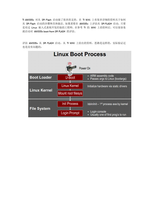
TI AM335x 对从SPI Flash 启动做了很多的支持,在TI WiKi 上有很多详细的资料关于如何从SPI Flash 启动的步骤和具体做法。
如果需要在AM335x 上评估从SPI FLASH 启动,只要是有过Linux 嵌入式系统开发经验的工程师,在参考TI 的WIKI 上的资料后,可以很容易就启动对AM335x boot from SPI FLASH 的评估。
评估AM335x 从SPI FLASH 启动,从TI WIKI 上给出的资料,思路是这样的,实际验证过也是没有问题的:●编译能从SPI 启动的SPL 和U-boot,生成MLO.spi 和u-boot.bin.make ARCH=arm CROSS_COMPILE=arm-arago-linux-gnueabi- am335x_evm_spiboot注:用am335x_evm_spiboot 替代am335x_evm 编译区别主要是将环境变量存储在SPI FLASH 中而不是NAND FLASH 中。
编译u-boot 具体方法参考/index.php/AM335x_U-Boot_User%27s_Guide#Building_U-Boo t●下载MLO.spi 和u-boot.bin 到SPI FLASH 中,可以通过网口、串口、USB 口、SD Card将上一步骤中编译好的文件下载到SDRAM 中,然后通过运行的u-boot 将程序烧写到SPI FLASH 中。
(以从UART boot 为例,当将Boot Switch 切换到从UART 启动后,重新上电,串口中断会收到CCCCCCC 的提示,然后通过Teraterm 或其他串口工具将文件u-boot-spl.bin 传输给Int RAM,内部的RBL 会执行这段代码并初始化SDRAM ,然后再下载u-boot.img 到SDRAM 并执行U-Boot.)具体下载方法参考:/index.php/AM335x_U-Boot_User%27s_Guide#Flashing_image s_to_NAND_in_UART_boot_mode上面是是以Uboot 烧写Nand 为例的,但烧写SPI FLASH 的方法是一样的,只不过命令由NAND Write 改为SF Write.关于用u-boot 烧写SPI FLASH 的方法,还可参考:/index.php/AM335x_U-Boot_User%27s_Guide#SPI_2●配置Linux Kernel McSPI 接口的驱动,MTD 相关配置,以及对filesystem (Jffs2)的支持。
AM335X美国TI处理器的功能介绍及工作原理
AM335X美国TI处理器的功能介绍及工作原理AM335X美国TI处理器的功能介绍及工作原理,详情如下:AM335X美国TI处理器功能介绍:高达1-GHz Sitara?ARM?Cortex?-A832位RISC处理器NEON?SIMD协处理器具有单错误检测(奇偶校验)的32KB L1指令和32KB数据高速缓存带有纠错码(ECC)的256KB二级缓存176KB片内启动ROM64KB专用RAM仿真和调试-JTAG中断控制器(多128个中断请求)片上存储器(共享的L3 RAM)64KB通用片上存储器控制器(OCMC)RAM所有大师的使用支持保留快速唤醒外部存储器接口(EMIF)mDDR(LPDDR), DDR2,DDR3,DDR3L控制器:mDDR:200 MHz时钟(400 MHz数据速率)DDR2:266 MHz时钟(532 MHz数据速率)DDR3:400 MHz时钟(800 MHz数据速率)DDR3L:400 MHz时钟(800 MHz数据速率)16位数据总线1GB的总可寻址空间支持一个x16或两个x8内存设备配置AM335x微处理器包含功能框图中所示的子系统,以及每个子系统的简要说明:包含功能框图中所示的子系统,以及每个子系统的简要说明:微处理器单元(MPU)子系统基于ARM Cortex-A8处理器,而PowerVR SGX?图形加速器子系统提供3D图形加速,以支持显示效果。
PRU-ICSS与ARM内核分离,从而允许独立的操作和时钟控制,从而提高了效率和灵活性。
PRU-ICSS支持其他外围设备接口和实时协议,例如EtherCAT,PROFINET,EtherNet / IP,PROFIBUS,以太网Powerlink,Sercos等。
此外,PRU-ICSS的可编程特性以及对引脚,事件和所有片上系统(SoC)资源的访问,为实现快速,实时响应,专用数据处理操作,自定义外围接口提供了灵活性,并从SoC的其他处理器内核分担任务。
德州仪器 Sitara AM335x ARM Cortex-A8硬件说明

Sitara™AM335x ARM®Cortex™-A8 Microprocessors(MPUs)Silicon Revisions2.1,2.0,1.0 Silicon ErrataLiterature Number:SPRZ360FOctober2011–Revised November2013Contents 1Introduction (3)1.1AM335x Device and Development Support Tool Nomenclature (3)1.2Revision Identification (4)2All Errata Listed With Silicon Revision Number (6)3Usage Notes and Known Design Exceptions to Functional Specifications (8)3.1Usage Notes (8)3.1.1LCD:Color Assignments of LCD_DATA Terminals (8)3.1.2DDR3:JEDEC Compliance for Maximum Self-Refresh Command Limit (8)3.1.3Boot:USB Boot ROM Code Uses Default DATAPOLARITY (9)3.1.4Boot:Multiplexed Signals GPMC_WAIT0,GMII2_CRS,and RMII2_CRS_DV Cause NAND BootIssue (9)3.1.5Pin Multiplexing:Valid IO Sets and Restrictions (10)3.1.6Boot:Multiplexed Signals GPMC_WAIT0and GMII2_CRS Cause NAND Boot Issue (10)3.1.7OSC1:RTC_XTALIN Terminal Has an Internal Pull-up Resistor When OSC1is Disabled (11)3.2Known Design Exceptions to Functional Specifications (12)Revision History (38)2Table of Contents SPRZ360F–October2011–Revised November2013Submit Documentation FeedbackCopyright©2011–2013,Texas Instruments IncorporatedSilicon ErrataSPRZ360F–October2011–Revised November2013Sitara™AM335x ARM®Cortex™-A8Microprocessors(MPUs)(Silicon Revision2.1,2.0,1.0)1IntroductionThis document describes the known exceptions to the functional specifications for the Sitara™AM335x ARM®Cortex™-A8Microprocessors(MPUs).[See the Sitara AM335x ARM Cortex-A8Microprocessors (MPUs)data manual(literature number SPRS717).]For additional information,see the latest version of the Sitara AM335x ARM Cortex-A8Microprocessors (MPUs)Technical Reference Manual(literature number SPRUH73).1.1AM335x Device and Development Support Tool NomenclatureTo designate the stages in the product development cycle,TI assigns prefixes to the part numbers of all microprocessors(MPUs)and support tools.Each device has one of three prefixes:X,P,or null(no prefix) (for example,XAM3358ZCE).Texas Instruments recommends two of three possible prefix designators for its support tools:TMDX and TMDS.These prefixes represent evolutionary stages of product development from engineering prototypes(TMDX)through fully qualified production devices and tools(TMDS).Device development evolutionary flow:X—Experimental device that is not necessarily representative of the final device's electrical specifications and may not use production assembly flow.P—Prototype device that is not necessarily the final silicon die and may not necessarily meet final electrical specifications.null—Production version of the silicon die that is fully qualified.Support tool development evolutionary flow:TMDX—Development-support product that has not yet completed Texas Instruments internal qualification testing.TMDS—Fully-qualified development-support product.X and P devices and TMDX development-support tools are shipped against the following disclaimer:"Developmental product is intended for internal evaluation purposes."Production devices and TMDS development-support tools have been characterized fully,and the quality and reliability of the device have been demonstrated fully.TI's standard warranty applies.Predictions show that prototype devices(X or P)have a greater failure rate than the standard production devices.Texas Instruments recommends that these devices not be used in any production systembecause their expected end-use failure rate still is undefined.Only qualified production devices are to be used.Sitara is a trademark of Texas Instruments.Cortex is a trademark of ARM Ltd or its subsidiaries.ARM is a registered trademark of ARM Ltd or its subsidiaries.All other trademarks are the property of their respective owners.3 SPRZ360F–October2011–Revised November2013Sitara™AM335x ARM®Cortex™-A8Microprocessors(MPUs)(SiliconRevision2.1,2.0,1.0) Submit Documentation FeedbackCopyright©2011–2013,Texas Instruments IncorporatedLot Trace CodeDevice RevisionLot Trace Code Device RevisionIntroduction 1.2Revision IdentificationThe device revision can be determined by the symbols marked on the top of the package.Figure 1provides an example of the AM335x device markings.Figure 1.Example of Device Revision Codes for the AM335x MicroprocessorNOTES:(A)Non-qualified devices are marked with the letters "X"or "P"at the beginning of the device name,while qualified devices have a "blank"at the beginning of the device name.(B)The AM3352and AM3359devices shown in this device marking example are two of several valid part numbers for the AM335x family of devices.(C)The device revision code is the device revision (A,B,and so on).(D)YM denotes year and month.(E)LLLL denotes Lot Trace Code.(F)962is a generic family marking ID.(G)G1denotes green,lead-free.(H)ZCE or ZCZ is the package designator.(I)S denotes Assembly Site Code.(J)On some "X"devices,the device speed may not be shown.4SPRZ360F–October 2011–Revised November 2013Sitara™AM335x ARM ®Cortex™-A8Microprocessors (MPUs)(Silicon Revision 2.1,2.0,1.0)Submit Documentation FeedbackCopyright ©2011–2013,Texas Instruments Incorporated Introduction Silicon revision is identified by a code marked on the package.The code is of the format AM3352x orAM3358x,where"x"denotes the silicon revision.Table1lists the information associated with each silicon revision for each device type.For more details on device nomenclature,see the device-specific datamanual.Table1.Production Device Revision CodesDEVICE REVISION CODE SILICON REVISION COMMENTS(blank) 1.0Silicon revision is newA 2.0Silicon revision2.0B 2.1Silicon revision2.1Each silicon revision uses a specific revision of TI's ARM®Cortex™-A8processor.The ARM Cortex-A8 processor variant and revision can be read from the Main ID Register.The DEVREV field(bits31-28)of the Device_ID register located at address0x44E10600provides a4-bit binary value that represents the device revision.The ROM code revision can be read from address2BFFCh.The ROM code versionconsists of two decimal numbers:major and minor.The major number is always22,minor number counts ROM code version.The ROM code version is coded as hexadecimal readable values;for example,ROM version22.02is coded as00002202h.Table2shows the ARM Cortex-A8Variant and Revision,Device Revision,and ROM Code Revision values for each silicon revision of the device.Table2.Silicon Revision VariablesSILICON ARM CORTEX-A8DEVICE ROMREVISION VARIANT AND REVISION REVISION REVISION1.0r3p2000022.022.0r3p2000122.032.1r3p2001022.035 SPRZ360F–October2011–Revised November2013Sitara™AM335x ARM®Cortex™-A8Microprocessors(MPUs)(SiliconRevision2.1,2.0,1.0) Submit Documentation FeedbackCopyright©2011–2013,Texas Instruments IncorporatedAll Errata Listed With Silicon Revision Number 2All Errata Listed With Silicon Revision NumberAdvisories are numbered in the order in which they were added to this document.Some advisory numbers may be moved to the next revision and others may have been removed because the design exception was fixed or documented in the device-specific data manual or peripheral user's guide.When items are moved or deleted,the remaining numbers remain the same and are not re-sequenced.Table3.All Usage NotesSILICON REVISION AFFECTED NUMBER TITLE1.02.0 2.1Section3.1.1LCD:Color Assignments of LCD_DATA Terminals X X XDDR3:JEDEC Compliance for Maximum Self-RefreshSection3.1.2X X XCommand LimitSection3.1.3Boot:USB Boot ROM Code Uses Default DATAPOLARITY X X XBoot:Multiplexed Signals GPMC_WAIT0,GMII2_CRS,andSection3.1.4XRMII2_CRS_DV Cause NAND Boot IssueSection3.1.5Pin Multiplexing:Valid IO Sets and Restrictions X X XBoot:Multiplexed Signals GPMC_WAIT0and GMII2_CRSSection3.1.6X XCause NAND Boot IssueOSC1:RTC_XTALIN Terminal Has an Internal Pull-upSection3.1.7X X XResistor When OSC1is DisabledTable4.All Design Exceptions to Functional SpecificationsSILICON REVISION AFFECTED NUMBER TITLE1.02.0 2.1DDR2,DDR3,mDDR PHY:Control and Status RegistersAdvisory1.0.1X X XConfigured for Write OnlyDebug Subsystem:EMU[4:2]Signals Are Not Available byAdvisory1.0.2X X XDefault After ResetDebug Subsystem:Internal Inputs Tied-off to the WrongAdvisory1.0.3X X XValueAdvisory1.0.4PRU-ICSS:Clock Domain Crossing(CDC)Issue XAdvisory1.0.5RTC:32.768-kHZ Clock is Gating Off XEXTINTn:Input Function of the EXTINTn Terminal isAdvisory1.0.6XInvertedAdvisory1.0.7Boot:Ethernet Boot ROM Code PHY Link Speed Detection XBoot:Ethernet Boot ROM Code Sends an Incorrect VendorAdvisory1.0.8XClass Identifier in BOOTP PacketEthernet Media Access Controller and Switch Subsystem:Advisory1.0.9C0_TX_PEND and C0_RX_PEND Interrupts Not Connected Xto ARM Cortex-A8GMII_SEL Register:RGMII1_IDMODE andAdvisory1.0.10RGMII2_IDMODE Bits Reset to Non-supported Mode of XOperationUSB:Attached Non-compliant USB Device that RespondsAdvisory1.0.11Xto Spurious Invalid Short Packet May Lock Up BusUART:Extra Assertion of FIFO Transmit DMA Request,Advisory1.0.12X X XUARTi_DMA_TXUSB:Data May be Lost When USB Subsystem is OperatingAdvisory1.0.13in DMA Mode and More Than One Endpoint is Transferring XDataGMII_SEL and CPSW Related Pad Control Registers:Advisory1.0.14Context of These Registers is Lost During Transitions of XPD_PERARM Cortex-A8:OPP50Operation on MPU Domain NotAdvisory1.0.15XSupported6SPRZ360F–October2011–Revised November2013 Sitara™AM335x ARM®Cortex™-A8Microprocessors(MPUs)(Silicon Revision2.1,2.0,1.0)Submit Documentation FeedbackCopyright©2011–2013,Texas Instruments Incorporated All Errata Listed With Silicon Revision Number Table4.All Design Exceptions to Functional Specifications(continued)SILICON REVISION AFFECTED NUMBER TITLE1.02.0 2.1RMII:50-MHz RMII Reference Clock Output Does NotAdvisory1.0.16X X XSatisfy Clock Input Requirements of RMII Ethernet PHYsAdvisory1.0.17VDDS_DDR:High-Power Consumption During DeepSleep0XROM:Ethernet Boot Code Does Not Change DefaultAdvisory1.0.18Direction of RMII1Reference Clock When Booting from XEthernet Using RMIIDDR3:Fully-Automated Hardware READ and WRITEAdvisory1.0.19X X XLeveling Not SupportedBoot:USB Boot ROM Code Overlapping Data in TXFIFOAdvisory1.0.20Xand RXFIFOSmartReflex:Limited Support Due to Issue Described inAdvisory1.0.21XAdvisory1.0.15EMIF:Dynamic Voltage Frequency Scaling(DVFS)is NotAdvisory1.0.22X X XSupportedEthernet Media Access Controller and Switch Subsystem:Advisory1.0.23X X XReset Isolation Feature is Not SupportedBoot:System Boot is Not Reliable if Reset is AssertedAdvisory1.0.24X X XWhile Operating in OPP50Boot:System Boot Temporarily Stalls if an Attempt to BootAdvisory1.0.25X X Xfrom Ethernet is Not SuccessfulAdvisory1.0.26I2C:SDA and SCL Open-Drain Output Buffer Issue X XAdvisory1.0.27LCDC:LIDD DMA Mode Issue X X XLCDC:Raster Mode,Hardware Auto Underflow RestartAdvisory1.0.28X X XDoes Not WorkLatch-up Performance:Latch-up Performance Limits forAdvisory1.0.29X XSilicon Revsions1.0and2.0OSC0and OSC1:Noise Immunity Improved When CrystalAdvisory1.0.30X X XCircuit is Connected Directly to PCB Digital GroundAdvisory1.0.31TSC_ADC:False Pen-up Interrupts X X XTSC_ADC:Terminals May be Temporarily ConnectedAdvisory1.0.32Together Through Internal Paths During Power-up X X XSequenceUSB Host:USB Low-Speed Receive-to-Transmit Inter-Advisory1.0.33X X XPacket DelayUSB2PHY:Register Accesses After a USB Subsystem SoftAdvisory1.0.34X X XReset May Lock Up the Entire SystemUART:Transactions to MDR1Register May CauseAdvisory1.0.35X X XUndesired Effect on UART OperationEMU0and EMU1:Terminals Must Be Pulled High BeforeAdvisory1.0.36X X XICEPick Samples7 SPRZ360F–October2011–Revised November2013Sitara™AM335x ARM®Cortex™-A8Microprocessors(MPUs)(SiliconRevision2.1,2.0,1.0) Submit Documentation FeedbackCopyright©2011–2013,Texas Instruments Incorporated2322212019181716151413121110987654321PIXEL_nR[7:3]G[7:2]B[7:3]16-bit panel24-bit panel23222120191817161514131211109876543210PIXEL_nB[0]G[0]R[0]B[1]G[1]R[1]B[2]R[2]B[7:3]G[7:2]R[7:3]16-bit panel24-bit panel3Usage Notes and Known Design Exceptions to Functional Specifications 3.1Usage NotesThis document contains Usage age Notes highlight and describe particular situations where the device's behavior may not match presumed or documented behavior.This may include behaviors that affect device performance or functional correctness.These notes may be incorporated into futuredocumentation updates for the device (such as the device-specific data manual),and the behaviors they describe may or may not be altered in future device revisions.3.1.1LCD:Color Assignments of LCD_DATA TerminalsThe blue and red color assignments to the LCD data pins are reversed when operating in RGB888(24bpp)mode compared to RGB565(16bpp)mode.In order to correctly display RGB888data from the SGX,or any source formatted as RGB in memory,it is necessary to connect the LCD panel as shown in Figure ing the LCD Controller with this connection scheme limits the use of RGB565mode.Any data generated for the RGB565mode requires the red and blue color data values be swapped in order to display the correct color.Figure 2.RGB888Mode LCD Controller Output Pin Mapping (LCD_DATA[23:0])When operating the LCD Controller in RGB565mode the LCD panel should be connected as shown in Figure ing the LCD Controller with this connection scheme limits the use of RGB888mode.Any data generated for the RGB888mode requires the red and blue color data values be swapped in order to display the correct color.Figure 3.RGB565Mode LCD Controller Output Pin Mapping (LCD_DATA[23:0])3.1.2DDR3:JEDEC Compliance for Maximum Self-Refresh Command LimitWhen using DDR3EMIF Self-Refresh,it is possible to violate the maximum refresh command requirement specified in the JEDEC standard DDR3SDRAM Specification (JESD79-3E,July 2010).This requirement states that the DDR3EMIF controller should issue no more than 16refresh commands within any 15.6-μs interval.To avoid this requirement violation,when using the DDR3EMIF and Self-Refresh (setting LP_MODE =0x2field in the PMCR),the SR_TIM value in the PMCR must to be programmed to a value greater than or equal to 0x9.8SPRZ360F–October 2011–Revised November 2013Sitara™AM335x ARM ®Cortex™-A8Microprocessors (MPUs)(Silicon Revision 2.1,2.0,1.0)Submit Documentation FeedbackCopyright ©2011–2013,Texas Instruments Incorporated3.1.3Boot:USB Boot ROM Code Uses Default DATAPOLARITYThe AM335x USB PHYs supports a DATAPOLARITY feature that allows the data plus(DP)and dataminus(DM)data signals to be swapped.This feature was added to simplify PCB layout.In some cases,the DP and DM data signals may need to cross over each other to connect to therespective USB connector pins.Crossing these signals on the PCB may cause signal integrity issues if not implemented properly since they must be routed as high-speed differential transmission lines.TheDATAPOLARITY feature in the USB PHYs can be used resolve this issue.The DATAPOLARITY feature is controlled by DATAPOLARITY_INV(bit23)of the respective USB_CTRL register.The USB boot ROM code uses the default value for DATAPOLARITY_INV when booting from USB.Therefore,the PCB must be designed to use the default DATAPOLARITY if the system must support USB boot.3.1.4Boot:Multiplexed Signals GPMC_WAIT0,GMII2_CRS,and RMII2_CRS_DV Cause NAND BootIssueThe AM335x device multiplexes the GPMC_WAIT0,GMII2_CRS,and RMII2_CRS_DV signals on thesame terminal.This causes a problem when the system must support NAND boot while an MII or RMII Ethernet PHY is connected to port2of the Ethernet media access controller and switch(CPSW).TheGPMC_WAIT0signal is required for NAND boot.The GMII2_CRS or RMII2_CRS_DV signal is required by the respective MII or RMII Ethernet PHY and the only pin multiplexing option for these signals isGPMC_WAIT0.In this case,there are two sources that need to be connected to the GPMC_WAIT0terminal.The NAND READY or BUSY output must source the GPMC_WAIT0terminal during NAND boot and the MII CRS or RMII CRS_DV output must source the GPMC_WAIT0terminal when the application software is using port 2of the CPSW.Therefore,a GPIO-controlled external2-to-1multiplexer must be implemented in thesystem to select between the two sources.The GPIO selected to control the2-to-1multiplexer needs to have an internal or external resistor that selects the NAND READY or BUSY output as soon as power is applied and remains in that state until the application software initializes the CPSW.The TI TS5A3157SPDT analog switch is an example device that can be used as a2-to-1multiplexer.This device inserts minimum propagation delay to the signal path since it is an analog switch.Thepropagation delay inserted by the2-to-1multiplexer must be analyzed to confirm it does not cause timing violations for the respective interface.The NAND,Ethernet PHY,AM335x VDDSHV1,AM335x VDDSHV3(when using the ZCZ package),and 2-to-1multiplexer IO power supply domains may need to operate at the same voltage since they share common signals.9 SPRZ360F–October2011–Revised November2013Sitara™AM335x ARM®Cortex™-A8Microprocessors(MPUs)(SiliconRevision2.1,2.0,1.0) Submit Documentation FeedbackCopyright©2011–2013,Texas Instruments Incorporated3.1.5Pin Multiplexing:Valid IO Sets and RestrictionsThe AM335x device contains many peripheral interfaces.In order to reduce package size and loweroverall system cost while maintaining maximum functionality,many of the AM335x terminals can multiplex up to eight signal functions.Although there are many combinations of pin multiplexing that are possible, only a certain number of sets,called IO Sets,are valid due to timing limitations.These valid IO Sets were carefully chosen to provide many possible application scenarios for the user.Texas Instruments has developed a Windows®-based application called Pin Mux Utility that helps asystem designer select the appropriate pin-multiplexing configuration for their AM335x-based productdesign.The Pin Mux Utility provides a way to select valid IO Sets of specific peripheral interfaces toensure the pin multiplexing configuration selected for a design only uses valid IO Sets supported by the AM335x device.A few IO Sets have additional restrictions not defined in the Pin Mux Utility.These additional restrictionsare described below:•MMC0,MMC1,MMC2Interfaces–Only Standard(STD)and High Speed(HS)modes are supported.SDR12,SDR25,SDR50modes as defined in SD3.0specification are not supported.•GEMAC_CPSW Interface–Operation of GEMAC_CPSW is not supported for OPP50.3.1.6Boot:Multiplexed Signals GPMC_WAIT0and GMII2_CRS Cause NAND Boot IssueThe AM335x device multiplexes the GPMC_WAIT0and GMII2_CRS signals on the same terminal.This causes a problem when the system must support NAND boot while an MII Ethernet PHY is connected to port2of the Ethernet media access controller and switch(CPSW).The GPMC_WAIT0signal is required for NAND boot.The GMII2_CRS signal is required by the MII Ethernet PHY and the only pin multiplexing option for these signals is GPMC_WAIT0.In this case,there are two sources that need to be connected to the GPMC_WAIT0terminal.The NAND READY or BUSY output must source the GPMC_WAIT0terminal during NAND boot and the MII CRSoutput must source the GPMC_WAIT0terminal when the application software is using port2of theCPSW.Therefore,a GPIO-controlled external2-to-1multiplexer must be implemented in the system to select between the two sources.The GPIO selected to control the2-to-1multiplexer needs to have an internal or external resistor that selects the NAND READY or BUSY output as soon as power is applied and remains in that state until the application software initializes the CPSW.The TI TS5A3157SPDT analog switch is an example device that can be used as a2-to-1multiplexer.This device inserts minimum propagation delay to the signal path since it is an analog switch.Thepropagation delay inserted by the2-to-1multiplexer must be analyzed to confirm it does not cause timing violations for the respective interface.The NAND,Ethernet PHY,AM335x VDDSHV1,AM335x VDDSHV3(when using the ZCZ package),and 2-to-1multiplexer IO power supply domains may need to operate at the same voltage since they share common signals.10SPRZ360F–October2011–Revised November2013 Sitara™AM335x ARM®Cortex™-A8Microprocessors(MPUs)(SiliconRevision2.1,2.0,1.0)Submit Documentation FeedbackCopyright©2011–2013,Texas Instruments Incorporated3.1.7OSC1:RTC_XTALIN Terminal Has an Internal Pull-up Resistor When OSC1is DisabledThe RTC_XTALIN terminal has an internal pull-up resistor that is turned on when OSC1is disabled.OSC1 is disabled by default after power is applied.This internal pull-up resistor was not properly documented in data sheet revisions D and earlier.These early data sheet revisions recommended an external pull-down resistor to be connected to theRTC_XTALIN terminal if OSC1was not used.The recommendation should have been to leave thisterminal open-circuit when not using OSC1.Connecting an external pull-down to the RTC_XTALIN terminal may cause unexpected leakage current.The current recommendation is to remove any external pull-down resistor from the RTC_XTALIN terminal and leave this terminal open-circuit when not using OSC1.3.2Known Design Exceptions to Functional SpecificationsThe following advisories are known design exceptions to functional specifications.Advisories arenumbered in the order in which they were added to this document.Some advisory numbers may bemoved to the next revision and others may have been removed because the design exception was fixed or documented in the device-specific data manual or peripheral user's guide.When items are moved or deleted,the remaining numbers remain the same and are not re-sequenced.Advisory1.0.1DDR2,DDR3,mDDR PHY:Control and Status Registers Configured for Write Only Revisions Affected 2.1,2.0,1.0Details The DDR2,DDR3,mDDR PHY control and status registers mapped in address range 0x44e12000-0x44E123FF are configured for write-only operations,so the contents ofthese register cannot be read.These registers must be configured by performing write-only operations.Workarounds There is no workaround for this issue.Advisory1.0.2Debug Subsystem:EMU[4:2]Signals Are Not Available by Default After Reset Revisions Affected 2.1,2.0,1.0Details All Debug subsystem components should remain unchanged when warm reset isasserted.For example,warm reset should not affect export of debug trace messages onthe EMU[4:0]signals.The AM335x EMU[4:2]signals can not be used to export trace messages from theDebug subsystem since AM335x does support warm reset and the EMU[4:2]signals arenot assigned to pins after reset is asserted.Workarounds Do not assert warm reset while performing trace functions.Advisory1.0.3Debug Subsystem:Internal Inputs Tied-off to the Wrong ValueRevisions Affected 2.1,2.0,1.0Details Internal inputs dbg_dpio_attr_dp_app_owner[4:0]and dbg_dpio_attr_dp_debug_only[4:0] to the Debug subsystem are used to report which EMU[4:0]signals can currently beused to export trace messages.These inputs were tied-off to the wrong value.The tie-offvalues used always indicates EMU[4:2]signals are not available and EMU[1:0]signalsare available to export trace messages.This should not cause a problem for EMU[4:2]since these signals can not be used toexport trace messages for the reason explained in advisory1.3.However,the AM335xpins used for EMU[1:0]signals may be configured as GPIO.The Debug subsystemwould not know these signals are not available for exporting trace messages when thesepins are configured as GPIO.Workarounds Do not configure the AM335x EMU[1:0]pins to operate as GPIO if you need to export trace messages.Advisory1.0.4PRU-ICSS:Clock Domain Crossing(CDC)IssueRevisions Affected 1.0Details The PRU-ICSS has a clock domain crossing issue when the MII receive multiplexer is configured to connect PR1_MII1signals to PRU0and PR1_MII0signals to PRU1.The multiplexer logic always uses the PR1_MII_MR0_CLK input to synchronize thePRU0MII receive signals and the PR1_MII_MR1_CLK input to synchronize the PRU1MII receive signals.This cause the wrong clock to be used when the MII receivemultiplexer is configured to connect PR1_MII1signals to PRU0and PR1_MII0signals toPRU1.As a result of this issue,support for EtherCAT media redundancy is not available. Workarounds There is no workaround for this issue.Advisory1.0.5RTC:32.768-kHZ Clock is Gating OffRevisions Affected 1.0Details The RTC has a clock gating issue that stops the internal32.768-kHz clock when theVDD_CORE voltage domain drops below the recommended operating range or thePWRONRSTn input terminal is held low.This issue has the following side effects:•The RTC counters stop incrementing when the32.768-kHz clock is gated.Thiscauses the RTC to lose time while the clock is gated.•A wakeup event applied to the EXT_WAKEUP input terminal is masked if theEXT_WAKEUP_DB_EN bit in the RTC PMIC register(0x98)is set to1which enablesthe de-bounce function for the EXT_WAKEUP input.This occurs because the32.768-kHz clock is being used to clock the de-bounce circuit.Workarounds Do not turn off the VDD_CORE power source or source a logic low to the PWRONRSTn input while expecting RTC to keep an accurate time.Do not enable the de-bounce circuit on the EXT_WAKEUP input if an external wakeupevent needs to be detected while the32.768-kHz clock is gated.Advisory1.0.6EXTINTn:Input Function of the EXTINTn Terminal is InvertedRevisions Affected 1.0Details The EXTINTn input is active high.Workarounds Use an active high interrupt source or use an external inverter to change the polarity of any active low interrupt source.Advisory1.0.7Boot:Ethernet Boot ROM Code PHY Link Speed DetectionRevisions Affected 1.0Details The device ROM code relies on the external PHY's Control Register(Register0),specifically bits0.6[Speed Selection(MSB)]and0.13[Speed Selection(LSB)],todetermine the operating speed of the link.If the external PHY does not update its link speed selection bits to reflect the currentoperating speed,the ROM code incorrectly assumes the PHY is operating at the speedindicated by the link speed selection bits and configure the device Ethernet MAC to thewrong speed.For example,if the default value of the PHY link speed selection bitsindicates100Mbps,when the PHY is actually operating at1Gbps,the ROM incorrectlyconfigures the device Ethernet MAC for100Mbps mode.The IEEE802.3specification states:When the Auto-Negotiation Enable(bit0.12)isenabled,bits0.6and0.13can be read or written to,but the state of bits0.6and0.13have no effect on the link configuration,and it is not necessary for bits0.6and0.13toreflect the operating speed of the link when it is read.While some PHYs update the linkspeed in these bits to reflect the current operating speed,other PHYs do not updatethese bits because it is not mandatory according to the specification.Workarounds When using Ethernet boot,an external PHY that updates the Register0link speedselection bits(0.6and0.13)to reflect the current operating speed is required.Advisory1.0.8Boot:Ethernet Boot ROM Code Sends an Incorrect Vendor Class Identifier inBOOTP PacketRevisions Affected: 1.0Details:When using Ethernet boot,the device ROM code should send a BOOTP request with a unique identifier to distinguish itself from other devices on the same network.Instead,the ROM code sends the same identifier,"DM814x ROM v1.0",for all devices(DM814x,DM816x,and AM335x);hence,the download host attempting to bootstrap the devicescan no longer determine which device is requesting the code to be downloaded.Applications using the DM814x,DM816x,and AM335x devices cannot coexist in thesame network if they are booted from Ethernet.Workaround:There is no workaround for this issue.For some applications,it might be necessary to uniquely identify and service BOOTPpackets from a client.The recommended approach to uniquely identify clients is to usethe MAC address.Every device comes with a unique MAC address.A list of MACaddresses and the device type can be made available to the host in advance,so that thehost can take device-specific action when it receives a BOOTP packet from a MACaddress on the host's list.。
基于AM33x的UBootSPL的CCS调试
基于AM335x的U-Boot/SPL 的CCS 调试在基于Linux的AM335x软件开发流程中,第一步就是U-Boot/SPL (Second Program Loader)的移植。
在移植中遇到问题比较常见,而U-Boot/SPL的调试手段比较简陋,不便于迅速找到问题。
利用仿真器可以单步调试的特点,就可以迅速定位到出问题的代码所在位置,加速移植的调试过程。
本文主要介绍如何用CCS+emulator调试基于AM335x的U-Boot/SPL。
1.AM335x Linux启动过程以及U-Boot/SPL调试代码的准备1.1 AM335x Linux的启动过程AM335x Linux的启动主要包括ROM,SPL, U-Boot 和kernel四个启动步骤:A.ROM codeROM code是固化在芯片内部的代码,当上电时序正确,而且晶振等芯片启动所需的条件都具备时,AM335x会从ROM code开始运行。
ROM code首先会读取sys_boot引脚上的配置,以确定存放SPL的存储器,或者可以获取SPL的外设。
具体可以参考AM335x 中的第26章Initialization。
ROM code会从相应的地方读取/获取SPL,并运行SPL。
B.SPLSPL和U-Boot 是bootloader的两个阶段。
这里分为两个阶段的原因是, ROM code中不会配置DDR,时钟等最小系统,所以ROM code只能把bootloader加载到片上SRAM中,而片上SRAM对成本影响很大,所以通常很小,例如在AM335x上只有64K,不足够放下整个U-Boot,所以将U-Boot分成两部分,SPL和U-Boot。
SPL主要的职责就是初始化DDR,时钟等最小系统,以读取U-Boot,并加载到DDR中。
具体来看,SPL 由ROM code加载到片上SRAM的起始位置,也就是0x402F0400。
SPL会进一步对芯片进行配置,主要包括以下几个方面以完成其主要职责:a.配置ARM core。
一种基于AM3358的嵌入式Linux系统烧写方法
一种基于AM3358的嵌入式Linux系统烧写方法摘要:微处理器技术的发展使嵌入式系统得到广泛应用,一个小型、实时、性能良好的嵌入式操作系统的研发和应用,就成为嵌入式系统进一步应用要解决的首要问题。
文章描述了将Linux-4.18内核及文件系统烧写到基于AM3358处理器目标板上的方法与过程。
介绍了目标平台和Linux-4.18内核,并说明了如何搭建移植环境,着重介绍了一种通过串口和网口进行系统烧写的方法,结果证明该方法是可行的。
烧写后的Linux系统运行良好。
为嵌入式技术应用和研究提供有益的帮助。
关键词:嵌入式Linux;Linux内核;AM3358处理器1引言随着微处理器技术的发展,嵌入式系统已经成为了计算机应用领域的一个重要的组成部分。
嵌入式Linux是按照嵌入式操作系统的要求设计的一种小型操作系统,由一个内核以及一些根据需要进行定制的系统模块组成。
其内核很小,非常适合移植到嵌入式系统中去。
大多数嵌入式Linux系统移植工作都是通过SD卡进行,但因为SD卡占据了一定的空间,可能会不符合工程项目要求,文章介绍了一种通过串口和网口的系统移植方法,可以减少器件所占空间,为工程应用带来便利。
2AM3358硬件平台介绍AM3358是TI公司使用A8处理器内核开发的一款嵌入式处理器。
专门为PDI、手持设备等开发,AM3358和它的其他系列相比,除了有宽温的特性和两倍的运行速度以外,还具备驱动强度控制等功能,是真正的工业级芯片,配合14mm×14mm的小体积,可以适合多数嵌入式场合使用,文章所设计的目标板硬件资源有:两片256M SDRAM,一片512M Nand Flash,一个调试串口,5个普通串口,2个千兆网口,一个USB HOST type-A接口,一个USB OTG接口,平台支持Linux 4.18版本。
文章主要基于AM3358的调试串口和eth0千兆网口进行的系统烧写。
网口硬件原理如图1,其他硬件原理暂不介绍。
- 1、下载文档前请自行甄别文档内容的完整性,平台不提供额外的编辑、内容补充、找答案等附加服务。
- 2、"仅部分预览"的文档,不可在线预览部分如存在完整性等问题,可反馈申请退款(可完整预览的文档不适用该条件!)。
- 3、如文档侵犯您的权益,请联系客服反馈,我们会尽快为您处理(人工客服工作时间:9:00-18:30)。
AM335x uboot spl分析芯片到uboot启动流程ROM → SPL→ uboot.img简介在335x 中ROM code是第一级的bootlader。
mpu上电后将会自动执行这里的代码,完成部分初始化和引导第二级的bootlader,第二级的bootlader引导第三级bootader,在ti官方上对于第二级和第三级的bootlader由uboot提供。
SPLTo unify all existing implementations for a secondary program loader (SPL) and to allow simply adding of new implementations this generic SPL framework has been created. With this framework almost all source files for a board can be reused. No code duplication or symlinking is necessary anymore.1> Basic ARM initialization2> UART console initialization3> Clocks and DPLL locking (minimal)4> SDRAM initialization5> Mux (minimal)6> BootDevice initialization(based on where we are bootingfrom.MMC1/MMC2/Nand/Onenand)7> Bootloading real u-boot from the BootDevice and passing control to it.uboot spl源代码分析一、makefile分析打开spl文件夹只有一个makefile 可见spl都是复用uboot原先的代码。
主要涉及的代码文件为u-boot-2011.09-psp04.06.00.03/arch/arm/cpu/armv7u-boot-2011.09-psp04.06.00.03/arch/arm/libu-boot-2011.09-psp04.06.00.03/driversLDSCRIPT := $(TOPDIR)/board/$(BOARDDIR)/u-boot-spl.lds这个为链接脚本__image_copy_end_end三、代码解析__start 为程序开始(arch/arm/cpu/armv7/start.S).globl _start 这是在定义u-boot的启动定义入口点,汇编程序的缺省入口是 start 标号,用户也可以在连接脚本文件中用ENTRY标志指明其它入口点。
.global是GNU ARM汇编的一个伪操作,声明一个符号可被其他文档引用,相当于声明了一个全局变量,.globl和.global相同。
该部分为处理器的异常处理向量表。
地址范围为0x0000 0000 ~ 0x0000 0020,刚好8条指令。
为什么是8条指令呢?这里来算一算。
首先,一条arm指令为32bit(位),0x0000 0020换算成十进制为2^5=32B(字节),而32(B) = 4 * 8(B) = 4 * 8 * 8( bit),所以刚好8条指令(一个字节Byte包含8个位bit)。
下面是在汇编程序种经常会遇到的异常向量表。
Arm处理器一般包括复位、未定义指令、SWI、预取终止、数据终止、IRQ、FIQ等异常,其中U-Boot中关于异常向量的定义如下:_start: b reset_start 标号表明 oot程序从这里开始执行。
b是不带返回的跳转(bl是带返回的跳转),意思是无条件直接跳转到reset标号出执行程序。
b是最简单的分支,一旦遇到一个 b 指令,ARM 处理器将立即跳转到给定的地址,从那里继续执行。
注意存储在分支指令中的实际的值是相对当前的 R15 的值的一个偏移量;而不是一个绝对地址。
它的值由汇编器来计算,它是 24 位有符号数,左移两位后有符号扩展为 32 位,表示的有效偏移为 26 位。
ldr pc, _undefined_instr tion //未定义指令ldr pc, _software_interrupt //软中断SWIldr pc, _prefetch_abort //预取终止ldr pc, _data_abort //数访问终止ldr pc, _not_usedldr pc, _irq //中断请求IRQldr pc, _fiq //快速中断FIQ#ifdef CONFIG_SPL_BUILD //该阶段为spl执行下面代码_undefined_instruction: .word _undefined_instruction_software_interrupt: .word _software_interrupt_prefetch_abort: .word _prefetch_abort_data_abort: .word _data_abort_not_used: .word _not_used_irq: .word _irq_fiq: .word _fiq_pad: .word 0x12345678 /* now 16*4=64 */#else_undefined_instruction: .word undefined_instruction_software_interrupt: .word software_interrupt_prefetch_abort: .word prefetch_abort_data_abort: .word data_abort_not_used: .word not_used_irq: .word irq_fiq: .word fiq_pad: .word 0x12345678 /* now 16*4=64 */#endif /* CONFIG_SPL_BUILD */.word为ARM汇编特有的伪操作符,语法如下:.word <word1> {,<word2>} …作用:插入一个32-bit的数据队列。
(与armasm中的DCD功能相同).balignl 16,0xdeadbeef.align伪操作用于表示对齐方式:通过添加填充字节使当前位置满足一定的对齐方式。
接下来是对各个段代码的定义略Rest: (arch/arm/cpu/armv7/start.S)bl save_boot_paramssave_boot_params: (arch/arm/cpu/armv7/ti81xx/lowlevel_init.S)#ifdef CONFIG_SPL_BUILDldr r4, =ti81xx_boot_device//ti81xx_boot_device = BOOT_DEVICE_NAND//启动方式ldr r5, [r0, #BOOT_DEVICE_OFFSET]and r5, r5, #BOOT_DEVICE_MASKstr r5, [r4]#endifbx lr回到reset:(arch/arm/cpu/armv7/start.S)//设置cpu的工作模式设置CPU的状态类型为SVC特权模式mrs r0, cpsrbic r0, r0, #0x1forr r0, r0, #0xd3msr cpsr,r0cpu_init_crit: (arch/arm/cpu/armv7/start.S)mov r0, #0 @ set up for MCRmcr p15, 0, r0, c8, c7, 0 @ invalidate TLBsmcr p15, 0, r0, c7, c5, 0 @ invalidate icachemcr p15, 0, r0, c7, c5, 6 @ invalidate BP arraymcr p15, 0, r0, c7, c10, 4 @ DSBmcr p15, 0, r0, c7, c5, 4 @ ISB//关闭mmu 缓存mrc p15, 0, r0, c1, c0, 0bic r0, r0, #0x00002000 @ clear bits 13 (--V-)bic r0, r0, #0x00000007 @ clear bits 2:0 (-CAM)orr r0, r0, #0x00000002 @ set bit 1 (--A-) Alignorr r0, r0, #0x00000800 @ set bit 11 (Z---) BTB#ifdef CONFIG_SYS_ICACHE_OFFbic r0, r0, #0x00001000 @ clear bit 12 (I) I-cache#elseorr r0, r0, #0x00001000 @ set bit 12 (I) I-cache#endifmcr p15, 0, r0, c1, c0, 0//调用初始化函数mov ip, lr @ persevere link reg across callbl lowlevel_init @ go setup pll,mux,memorylowlevel_init:(arch/arm/cpu/armv7/ti81xx/lowlevel.S)/* The link register is saved in ip by start.S */mov r6, ip/* check if we are already running from RAM */ldr r2, _lowlevel_init_TEXT_BASE:.word CONFIG_SYS_TEXT_BASE /* Load address (RAM) */#define CONFIG_SYS_TEXT_BASE 0x80800000SDRAM的前8MB作为spl的bss段然后前64bytes做为u-boot.img的头ldr r3, _TEXT_BASEsub r4, r2, r3sub r0, pc, r4//设置堆栈指针/* require dummy instr or subtract pc by 4 instead i'm doing stack init */ ldr sp, SRAM_STACKmark1:ldr r5, _mark1sub r5, r5, r2 /* bytes between mark1 and lowlevel_init */sub r0, r0, r5 /* r0 <- _start w.r.t current place of execution */mov r10, #0x0 /* r10 has in_ddr used by s_init() */ands r0, r0, #0xC0000000 /* MSB 2 bits <> 0 then we are in ocmc or DDR */ cmp r0, #0x80000000bne s_init_startmov r10, #0x01b s_init_starts_init_start:(arch/arm/cpu/armv7/ti81xx/lowlevel.S)mov r0, r10 /* passing in_ddr in r0 */bl s_init初始化pll mux memery/* back to arch calling code */mov pc, r6call_board_init_f:(arch/arm/cpu/armv7/start.s)//设置堆栈指针,并调用board_init_fldr sp, =(CONFIG_SYS_INIT_SP_ADDR)bic sp, sp, #7 /* 8-byte alignment for ABI compliance */ldr r0,=0x00000000bl board_init_fvoid board_init_f(ulong dummy)『u-boot-2011.09-psp04.06.00.03/arch/arm/cpu/armv7/omap-common/spl.c』调用relocate_code(CONFIG_SPL_STACK, &gdata, CONFIG_SPL_TEXT_BASE);这里使用了 CONFIG_SPL_STACK#define CONFIG_SPL_STACK LOW_LEVEL_SRAM_STACK#define LOW_LEVEL_SRAM_STACK (SRAM0_START + SRAM0_SIZE – 4) gdata 为.bss 前一段的空间描述镜像头#define CONFIG_SPL_TEXT_BASE 0x402F0400relocate_code: (arch/arm/cpu/armv7/start.s)重载定位代码jump_2_ram: (arch/arm/cpu/armv7/start.s)跳转到spl的第二阶段board_init_r:(u-boot-2011.09-psp04.06.00.03/arch/arm/cpu/armv7/omap-common/spl.c) 初始化时钟: timer_init()i2c 初始化: i2c_init();获取启动方式 omap_boot_device();判断启动方式从不同的地方装载镜像从mmc 中装载镜像 spl_mmc_load_image();从nand 中装载镜像 spl_nand_load_image();从 uart 中装载镜像 spl_ymodem_load_image();判断镜像类型跳转到镜像中执行镜像 jump_to_image_no_args();装载镜像将会从配置的存储介质中读取数据及uboot镜像然后跳转到uboot中执行uboot注:文章版权属于成都莱得科技有限公司所有,转载请注明出处。
