系列固化炉说明书
铝合金固溶炉说明书
铝合金固溶炉说明书一、产品组成系统说明(一)、燃气式铝合金固溶炉用途:该电炉主要用于铝合金零件(淬火)固溶处理,其工作性质属于间歇加热使用。
(二)、电炉占用厂房空间及电力配置要求:燃气立式固溶炉空间:长16.0M(含水槽移出尺寸)×宽6.5M×高6.5M(地面标高)所用电力要求:≥45Kw(若水槽加热另+60KW)天然气供应:≥40M3/h(主管压力:≤0.1Mpa.DN50)(三)、主要技术参数:1、额定温度:650℃2、额定功率:105KW×4=420KW3、燃料气源:天然气(8400Kcal/M3)4、最大燃气消耗40M3/h5、平均燃气消耗25-30M3/h6,天然气烧咀: 4台高速直焰(105KW/台)7、空气助燃风机: 电机:2.2KW 风压:7Kpa 风量:500M3/h8、工艺温度:525- 545℃9、温度均匀性:±5℃10、温区:1区11、炉膛有效尺寸:长3400×宽2400×高1800mm12、料框尺寸:长3000×宽2000×高1500mm13、淬火转移时间:≤10S15、温控精度:±1℃16、温度记录方式:中长图记录仪17、燃气执行元件:电动执行器(4-20mA输出)18、炉型:立式炉19、炉内循环风机电机功率:11KWX2台( 1250r/min)风机风量: 35000M3/台20、提升电机功率:(双速电机4-8级) 11-7KW21、水槽加热功率:60KW22、水槽行走电机功率:7.5KW(7.5m/min)23、水槽搅拌电机功率: 5.5KWX2(950r/min)24、提升重量:~2.0T(≥200件)每炉处理量:工件尺寸:600X500X130mm,7.8Kg/件X200件/筐25、炉门运动气缸: DN200×2600S工作压力:0.4MPa (*压缩空气由用户配备)26、料筐数量:2件24、炉内耐热钢材料:4mm1Cr18Ni9Ti25、实炉升温时间:(室温--545℃)≤1.5h26、炉表温升: 室温+30℃27、淬火水温: ≤60℃(四)、电炉的结构特点及性能:(见该电炉的方案图)燃气式铝合金固溶炉主要由炉体(炉壳、炉衬)、炉门气动机构、燃气加热系统、炉气循环系统、淬火移动水槽、料盘淬火升降机构、燃烧及炉温控制系统等组成。
2023年自动旋转固化炉操作规程

2023年自动旋转固化炉操作规程操作规程 - 自动旋转固化炉____年版本第一章:引言1.1 目的本操作规程的目的是为了确保自动旋转固化炉的安全操作,并提供指导以确保炉子的正常运行和产品的高质量。
1.2 适用范围本操作规程适用于____年的自动旋转固化炉操作,并适用于所有涉及到炉子的工作人员。
第二章:设备概述2.1 设备描述自动旋转固化炉是一种用于固化材料的设备,其主要由炉膛、旋转系统、加热系统和控制系统组成。
2.2 工作原理自动旋转固化炉通过加热系统将炉膛内的温度升高到所需的固化温度,并通过控制系统对炉膛内的温度、旋转速度等参数进行控制,以确保炉子的正常运行。
2.3 安全注意事项在操作自动旋转固化炉时,必须遵守以下安全注意事项:a. 必须戴上适当的防护装备,如耐高温手套、护目镜等;b. 在操作之前,确保炉子处于停止状态,并检查所有的控制开关和安全装置是否正常工作;c. 炉膛内的温度非常高,请务必小心操作,避免接触炉膛表面和热门零部件;d. 任何时候都不要将手或其他物体伸入炉膛中,以免发生危险。
第三章:操作步骤3.1 准备工作a. 了解固化物料的固化温度和固化时间,并准备好相关材料;b. 检查炉膛内是否有残留物,如果有,清理干净;c. 检查加热系统和控制系统的运行状态,确保正常工作;d. 确保所有安全装置和控制开关处于正常工作状态。
3.2 启动炉子a. 打开炉子主电源,并确保控制系统和加热系统正常启动;b. 设定所需的固化温度和固化时间,并将旋转速度设定为适当的数值;c. 检查炉子的运行状态,确保温度和旋转速度等参数显示正常。
3.3 将材料放入炉膛a. 将要固化的材料放入炉膛内,并平铺整齐,确保材料均匀分布;b. 关闭炉膛门,并确保密封良好。
3.4 监控炉子运行a. 在固化过程中,持续监控炉子的温度、旋转速度等参数,并确保其保持在所需的范围内;b. 如发现温度或其他参数异常,请及时调整控制系统。
固化炉安全操作规程
固化炉安全操作规程为了确保固化炉的正常使用,保护员工的生命财产安全,制定此固化炉操作规程。
一、固化炉介绍本固化炉用于固定电子元件等物品,在固化的过程中需要打开金属罩,以便完成固化过程。
固化炉温度可根据需要设定,达到设定温度后,炉子内置定时器会停止加热,凉炉后关闭电源。
二、操作要求1.禁止未经培训的员工操作固化炉;2.操作人员需核对固化炉是否处于正常状态。
检查是否有异常气味,正常温度等;3.打开时先关闭固化炉总电源开关;4.确保金属罩已经完全张开,这时可开启固化炉前面的开关;5.严格按照要求设置温度和时间;6.操作人员需时刻关注固化炉的运行状态;7.固定完后将电源关闭,定时器会停止加热,凉炉后关闭总电源开关;三、操作注意事项1.固化炉定期检查,检查固化炉内是否有异物,清洁炉子;2.设备平稳移动,防止碰撞、颠簸而导致设备受损;3.确保众人的安全,固化炉应靠墙角定位;4.严禁在设备电源处擅自拆卸设备、接线;5.操作人员未经培训禁止轻信他人盲目操作设备;6.运行设备时,严禁在设备下手部及工具。
四、应急措施1.当固化炉发生异常情况时,应第一时间关闭操纵面板上的开关;2.发生火灾或炉子过烧,要及时关闭炉子和总开关电源,用灭火器或其他灭火设备进行灭火;3.发现烟雾、有毒燃气等危险物应及时开启通风设备,确保通风;4.对于紧急情况,要立即拨打公司安全电话,并采取相应的应急措施。
五、安全教育1.新员工要接受固化炉操作的培训,合格后方可独立操作;2.员工每三个月至少接受一次安全操作规程培训;3.管理人员每月应该召开一次安全规程培训,及时通报安全事故及经验教训;4.每年至少进行一次应急演练,提高员工的应急处置能力。
以上为固化炉安全操作规程,希望大家认真遵守,确保设备的正常操作及员工的安全。
UV固化炉设备作业指导书A版
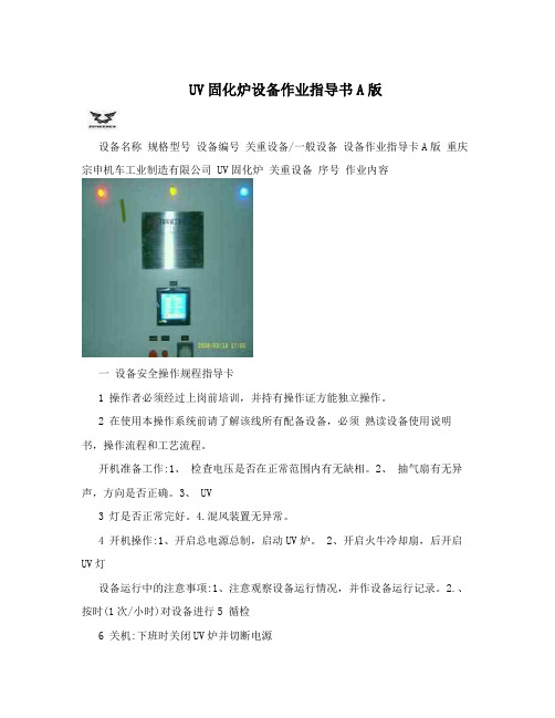
UV固化炉设备作业指导书A版设备名称规格型号设备编号关重设备/一般设备设备作业指导卡A版重庆宗申机车工业制造有限公司 UV固化炉关重设备序号作业内容一设备安全操作规程指导卡1 操作者必须经过上岗前培训,并持有操作证方能独立操作。
2 在使用本操作系统前请了解该线所有配备设备,必须熟读设备使用说明书,操作流程和工艺流程。
开机准备工作:1、检查电压是否在正常范围内有无缺相。
2、抽气扇有无异声,方向是否正确。
3、 UV3 灯是否正常完好。
4.混风装置无异常。
4 开机操作:1、开启总电源总制,启动UV炉。
2、开启火牛冷却扇,后开启UV灯设备运行中的注意事项:1、注意观察设备运行情况,并作设备运行记录。
2.、按时(1次/小时)对设备进行5 循检6 关机:下班时关闭UV炉并切断电源每周至少一次对设备的混风装置、UV灯管进行一次全面检查并清洁炉胆,发现问题及时处理。
对不能排除的7 设备故障,及时向设备动力课长或相关部门报告停机后根据运行情况进行维修保养,保持设备状态良好,清洁卫生。
每周至少一次对设备转动部位进行一次8 全面检查,发现问题及时处理。
对不能排除的设备故障,及时向设备动力课长或相关部门报告。
操作人员应该坚守岗位做好本职工作,做到勤听、勤看、勤检查,严格遵守操作规程。
应该认真填写设备点注意指示灯及工作温度 9 检记录,对设备运行的问题要力所能及处理,并详细作好设备运行书面记录。
二设备日常点检指导卡自主检查专职检查备注点检内容和标准序号点检项目检查方法/工具检查频次检查方法/工具检查频次 1 机械 1. 抽气扇工作正常,运行灵活。
2火牛散热装置目测/试运行每天目测/万用表每周 2 电器 1.控制柜仪表、按钮无破损、显示正常。
2.各共位照明目测/试运行每天目测/万用表每周正常。
3. UV 灯线路规范、完好,无裸露。
3 性能良好,运转正常目测/试运行每天眼观/万用表每周4 外观设备表面无油漆脱落,无泡、冒、滴、漏现象目测、听/扳手等每班目测/扳手等每周5 清洁设备表面无灰尘、无杂物目测、听/无每班 / 每周6 防护装置完好无损坏目测、听/无每班目测、焊接/焊机每周7 其它通风管路内无堵塞目测/试运行每天 / 每周三设备润滑指导卡序号润滑部位油的种类达到标准润滑周期责任人备注无 / / / /四设备定期维护指导卡自主维护专职维护备注达到标准序号维护内容维护方法/工具维护频次维护方法/工具维护频次烘房内部清洁无灰尘、污渍、杂物、集 1 清洁/拖帕等每周 / 每周油2 抽气扇工作正常,运行灵活目测/试运行每天目测/试运行每周3 通风管路管路内无堵塞触摸/试运行每天触摸/试运行每周4 配电柜各按钮无破损、有效目测/试运行每天目测/万用表每周5 配电柜显示仪表、显示正常目测/试运行每天目测/万用表每周6 控制柜线路规范 / / 规整线路/万用表每周7 UV灯线路规范、无损坏目测/试运行每天目测/万用表每周 10 火牛散热装置工作正常目测每天目测/万用表每周 9 设备表面清洁、无杂物目测每天目测每周 10 各工位的照明完好,线路无裸露 / / 更换/扳手/万用表每周 11 自然风槽无杂物清理次/半年清洁 \ 标记处数更改文件签字日期编制(日期) 审核(日期) 会签(日期) 标准化(日期) 批准(日期)。
自动旋转固化炉操作规程范本(2篇)
自动旋转固化炉操作规程范本操作规程:自动旋转固化炉1. 安全操作要求1.1 在操作固化炉前,必须佩戴适当的个人防护装备,包括安全鞋、眼镜和手套等。
1.2 操作人员必须熟悉固化炉的结构、性能和工作原理,并接受相关培训。
1.3 在操作过程中,必须严格按照操作规程进行操作,不得随意更改或省略步骤。
1.4 在操作过程中,必须保持清醒状态,严禁酒后或疲劳驾驶。
1.5 操作固化炉时,周围必须保持整洁,防止杂物阻挡炉门或引发火灾。
1.6 使用固化炉时应注意电源的安全,确保电源连线不受损坏或短路。
1.7 当需要维修、清洁或更换固化炉部件时,必须切断电源并等待相关设备冷却后进行。
2. 操作步骤2.1 开机准备2.1.1 检查固化炉周围是否有杂物或危险物品,如有必要,进行清理。
2.1.2 确保电源连线无损坏或短路。
2.1.3 检查固化炉的温度调节器和控制器是否正常工作。
2.1.4 打开炉门,检查固化炉内部是否有残留物,如有必要,进行清理。
2.2 加载物料2.2.1 将待固化的物料放置于固化炉的加热盘上,并确保物料摆放均匀。
2.2.2 关闭炉门,确保炉门密封良好,防止炉内温度外溢。
2.3 设置固化参数2.3.1 通过温度控制器设置固化炉的温度,根据物料特性和固化要求进行调整。
2.3.2 设置固化炉的时间,在固化后自动关机或发出提示信号。
2.4 启动固化炉2.4.1 打开固化炉的电源开关,启动设备。
2.4.2 按照设定的温度和时间进行固化。
2.4.3 在固化过程中,定期检查固化炉的工作状态,确保温度和时间设定符合要求。
2.4.4 如有需要,可以进行温度和时间的微调。
2.5 固化完成后2.5.1 当固化时间到达设定值时,固化炉会自动停止工作,发出提示信号。
2.5.2 关闭固化炉的电源开关。
2.5.3 打开固化炉的炉门,将固化好的物料取出并进行检查。
2.6 关机与清洁2.6.1 清除固化炉内的残留物。
2.6.2 关闭固化炉的炉门,确保炉门关闭完全。
网带式达克罗固化炉方案说明

网带式达克罗固化炉方案说明一、设备的主要用途该设备可供对涂膜零件进行预热固化烘干,并经过强冷后完成零件处理的工艺过程.二、主要技术参数1.炉膛有效尺寸9000×1000×500(mm)2.予热固化段温度室温~350℃(可调)3.予热段长度 3300mm4.固化段 6700 mm5..前移料段长度 3000mm6..后冷却段长度 5000mm7.加热区功率 3区(80KW、80KW、80KW)8.温度均匀性±5℃(有效炉膛截面温差,排风口ø1000mm内±10℃)9.温度控制精度±1℃10.烘道外表温升≤20℃11.烘道循环风机功率 2.2KW×6台12.排风风机 1.1KWX2台13.冷却排抽风~4KW14.出料冷却风扇功率 0.13KW×台15.网带输送功率 1.1KW(变频调速)16.设备生产能力 800Kg/h17.网带承载能力≥200kg/㎡18.网带的宽度 1000mm19.网带的运行速度 0.15~1m/min(无级可调)三、设备的结构简介该网带固化炉主要由前后传动架、输送机构、加热炉休、急冷系统和电器控制组成.1.前后传动架皆由型钢焊接而成,分别置放于炉体的两端,可供输送带的支撑和前后链轮组的安装,使网带得以循回传送,传送的动力选用大速比的减速机和变频调速电机配备。
使网带的传送速度可以无级调控.整套动力设施置放于设备的出料端.物件的传送采用链条拖动网带的方式输送,可使物料的转移动作更有序,可控。
优质的不锈钢网带可长期使用,无氧化和腐蚀,从根本上提高设备的使用寿命。
2.炉体的框架为型钢焊成的结构件,外部按装有优质成型后的碳钢板,也可作保温层的外壁,它与内腔的不锈钢(304)钢板之间形成的一个空腔为保温层,保温层中填充了优质保温材料,用以保护炉内的温度.在整个炉子的内腔与有效工作尺寸之间设置了一层隔板,使之与炉内壁亦产生一个空腔。
固化炉说明书

GH2500型固化炉使用说明书威海东发精工机械有限责任公司目录一、用途与结构特征二、主要技术参数三、电路图四、温度控制五、注意事项一、用途与结构特征本设备主要适用于碳素竿、玻璃钢竿及高尔夫球竿的竿体固化。
它的工作原理是:在体外加温箱加温,经风筒由炉顶进风,通过交叉调风窗、把热风均匀地吹向炉内,在炉内下方两侧经调风窗,一侧直接回风到风箱,另一侧经炉底下方回风到体外风箱,进行循环。
炉内温度根据需要自行调节。
设计独特,结构合理,是固化的理想设备。
炉内容积可按用户需要订做。
二、主要技术参数1、炉内容积:1200X1200X2500mm2、炉内温度:0—280℃+5℃3、风机:2.2KW 1410r/min4、电热管:24KW5、电源:380V/50HZ6、重量:约1300kg7、外形尺寸:1600X2200X3580mm四、温度控制炉内温度控制详请阅读:AI-518P型人工智能温度控制器使用说明书。
(附说明书一本)(1)正常启动:接通电源开关,启动风机,再按“智能温控表”上右边第二个按钮“∨”,按住1秒,下面显示器上显示为:RUN,表明为工作状态;按住2秒以上为暂停,显示器显示HOLD。
注意:运行中不可按“△”STOP,如按的话,会造成程序归零。
(2)温度程序设定修改如下:启动风机以后,按智能温控表左边第二个按钮“<”,按一下,表上显示“d-01”,再按”,显示下一个数据“t-01”,按“∨”、“∧”键来设定修改数据,按“<”键2秒以上,返回上一个数据(详见说明书16~19页)(3)程序编排如下:(详见说明书44~47页)温度C2—C5 (C1=30℃)时间t1—t4(t1=30分钟)内容根据需要自行设定。
喷涂固化炉烘干炉柜炉操作指导书

喷涂固化炉烘干炉柜炉操作指导书一、引言喷涂固化炉烘干炉柜炉是一种用于涂料固化和烘干的设备,广泛应用于涂装行业。
本操作指导书旨在向操作人员提供有关喷涂固化炉烘干炉柜炉的使用和操作的指导。
二、设备概述喷涂固化炉烘干炉柜炉由炉体、加热系统、控制系统等组成。
炉体为密封结构,内部设有加热元件。
加热系统可根据需要进行调节,控制系统用于实时监测和控制温度。
三、操作准备1. 检查炉体和所有配件是否完好无损。
2. 准备涂料和待烘干的工件。
3. 确保操作环境通风良好。
四、操作步骤1. 打开炉门,并将待烘干的工件放入炉体内。
2. 关上炉门,确保炉体密封。
3. 打开控制系统,将设定温度调至所需温度。
4. 等待炉体温度升至设定温度,并保持一段时间,使工件彻底固化。
5. 关闭控制系统,待炉体冷却后打开炉门。
6. 取出已经固化和烘干的工件,进行下一步操作。
五、注意事项1. 操作人员必须佩戴符合安全标准的防护设备,如防护眼镜、手套等。
2. 在使用喷涂固化炉烘干炉柜炉时,应确保操作环境通风良好,以防止有害气体的积聚。
3. 使用过程中应严格按照操作指导书的要求进行操作,不得随意调整设备参数。
4. 炉体表面温度较高,请切勿直接接触以避免烫伤。
5. 涂料固化和烘干过程中,应确保工件均匀受热,避免局部过热或不均匀问题的发生。
六、维护保养1. 定期清洁炉体内部和外部的积尘和污垢。
2. 检查加热元件和控制系统的工作状态,如有故障及时维修和更换。
3. 定期检查炉体密封性能,如有破损及时更换密封件。
4. 特殊情况下,如长时间未使用,应切断电源,确保设备安全。
七、故障排除在使用喷涂固化炉烘干炉柜炉过程中,可能会遇到一些故障,如设备无法启动、温度无法控制等。
如果遇到故障,请立即切断电源,并联系相关技术人员进行维修。
结语本操作指导书主要介绍了喷涂固化炉烘干炉柜炉的使用和操作,以及日常的维护保养和故障排除。
操作人员在使用设备前应仔细阅读本指导书,并按照要求进行操作,以确保设备的正常使用和安全性能。
固化炉安全操作规程范本(二篇)

固化炉安全操作规程范本第一章总则第一条为了确保固化炉的安全运行,保障员工的人身安全和设备的完好,制定本操作规程。
第二条本规程适用于所有使用固化炉的操作人员。
第三条操作人员必须严格按照本规程的要求进行操作,禁止擅自违反规程进行操作。
第四条本规程的内容包括固化炉的基本要求、操作流程、安全措施和事故处理等。
第二章固化炉的基本要求第五条固化炉必须符合国家相关标准和规范,并具有必要的安全保护设施。
第六条固化炉周围必须保持整洁,并设置明显的警示标识。
第七条固化炉必须定期进行检查和维护,确保设备的正常运行。
第三章操作流程第八条进行操作前,必须全面了解固化炉的使用方法和安全防护措施。
第九条制定详细的操作计划,明确操作的步骤和顺序。
第十条操作人员必须经过专业培训并持有相应的资格证书才能进行操作。
第十一条操作人员必须正确佩戴防护装备,包括耐高温手套、护目镜、耐酸碱服装等。
第十二条操作开始前,必须检查固化炉的工作状态并确认设备和周边环境的安全。
第十三条操作中禁止将手、头或其他身体部位靠近固化炉的加热部分。
第十四条操作过程中必须时刻注意设备的运行状态,发现异常情况要及时停止操作并上报。
第十五条操作完成后,必须将固化炉彻底清理干净,并关闭相关设备和电源。
第四章安全措施第十六条操作人员在操作前必须穿戴个人防护装备,并严禁穿戴有易燃易爆物品。
第十七条操作人员必须严格按照操作规程进行操作,禁止随意调整、拆卸设备。
第十八条操作人员必须保持清醒,禁止疲劳驾驶或酒后操作固化炉。
第十九条操作人员必须遵守安全用电规定,确保设备的电气安全。
第二十条操作人员禁止将易燃物品置放在固化炉附近,确保周围环境的安全。
第二十一条固化炉周围必须保持良好的通风环境,防止有毒气体的积聚。
第五章事故处理第二十二条如果发生固化炉故障或事故,操作人员必须立即停止操作,并采取相应的应急措施。
第二十三条在事故处理过程中,操作人员必须根据实际情况,合理选择应急措施。
第二十四条发生事故后,必须立即上报领导,并按要求保存相关证据。
固化炉安全操作规程

固化炉安全操作规程固化炉是一种用于生产过程中的热处理设备,旨在通过高温炉膛中的处理介质将物体固化或硬化。
为了确保固化炉的安全操作,以下是一份详细的固化炉安全操作规程,包括清洁、炉膛操作、温度控制、燃料使用、维护和紧急情况处理等方面。
1. 清洁:- 在每次使用前和使用结束后清理炉膛内的残留物。
使用专用工具和适当的清洁剂进行清洁,确保炉膛内的杂质、灰渣和废料等被完全清除。
- 定期检查炉膛齿轮、链条等传动装置的清洁情况,并及时清理和润滑。
2. 炉膛操作:- 使用前检查固化炉的炉膛、隔板、绝缘材料等部件的完整性和紧固情况,确保没有损坏或松动的部件。
- 确保炉膛内的物体摆放整齐,不得阻碍炉膛的通风和加热效果。
- 在操作过程中,注意炉膛内的温度变化和炉膛表面的热辐射,并避免直接接触炉膛和热物体。
- 炉膛内不得存放易燃、易爆、有毒或有害的物质,以防止火灾、爆炸和危险气体泄露等事故。
3. 温度控制:- 在使用固化炉前,确认温度控制仪器的准确性和可靠性,并校准或更换不准确或损坏的仪器。
- 在进行温度调节时,逐渐提高或降低温度,避免急剧的温度波动和温度过高或过低。
- 不得超出固化炉的额定温度范围,并及时调整温度控制装置,以保持稳定的工作温度。
4. 燃料使用:- 使用固化炉时,确保燃料的正确选择和供应,避免使用不适合的燃料或燃料供应中断。
- 对燃料的存储和供应系统进行定期维护和检查,确保没有泄漏或堵塞的情况。
- 在添加或更换燃料时,确保固化炉已经完全冷却,并采取适当的防护措施,防止燃料的溅出、漏油或点火。
5. 维护:- 定期检查固化炉的通风系统、电气设备、传动装置等部件和设备的安全性和工作状态,确保没有异常或损坏的情况。
- 定期检查和更换固化炉的耗材和易损件,如密封圈、加热器、传感器等。
- 在进行维护或更换部件时,必须切断电源,并按照操作手册和技术要求进行操作,避免误操作或操作错误导致事故。
6. 紧急情况处理:- 在发生火灾、漏油、燃烧不完全等紧急情况时,立即切断燃料供应和电源,并使用灭火器、排烟设备等进行灭火和处理。
黑色固化炉控制器操作说明书
固化炉控制器说明书XMT-808P程序型仪表用于需要按一定时间规律自动改变给定值进行控制的场合。
它具有强大的编程及操作能力,可进一步提高控制设备的自动化程序。
它具备30段程序编排功能,可设置任意大小的给定值升、降斜率;具有跳转、运行、暂停及停止等可编程/可操作命令,可在程序控制运行中修改程序;具备二路事件输出功能。
可通过报警输出控制其他设备联锁动作,进一步提高设备自动化能力;具有停电处理模式,使程序执行更有效率及更完善。
一、功能及概念程序段:段号可从1-30,当前段(STEP)表示目前正在执行的段。
设定时间:指程序段设定运行的总时间,单位为分,有效数值从1-9999。
运行时间:指当前段已运行时间,当运行时间达到设置的段时间时,程序自动转往下一段运行。
跳转:程序段可编程为自动跳转到1-30段中的任意段执行,可实现循环控制。
通过修改STEP的数值也可实现跳转。
另外,如果程序段号已运行到第30段,则自动再跳回到第一段运行。
运行/暂停(run/hold):程序在运行状态时,时间计时,给定值按预先编排的程序曲线变化。
程序在暂停状态下,时间停止计时,给定值保持不变。
仪表在程序段中编入暂停操作,也可由人随时执行暂停/运行操作。
事件输出:事件输出有程序编排发生。
可在程序运行中控制2路报警开关动作,以方便控制各种外部设备同步或连锁工作。
比如,在一个控制过程结束时自动接通一个继电器开关,再用开关控制电铃来通知操作人员等等。
停电/开机事件:指仪表接通电源或在运行中意外停电,可提供多种处理方案供用户选择。
曲线拟合:曲线拟合是XMT-808P型仪表采用的一种控制技术,由于控制对象通常具有时间滞后的特点,所以仪表对线性升、降温及恒温曲线在折点处自动平滑化,平滑程度与系统的滞后时间参数t有关,t越大,则平滑程度也越大,反之越小。
控制对象的滞后时间(如热惯性)越小,则程序控制效果越好。
按曲线拟合方式处理程序曲线,可以避免出现超调现象。
PVA IR2000红外固化炉说明书
Using The Electronic ManualRequirementsThe following is a list of system requirements for the electronic manual:Pentium Processor64 MB of RAM50 MB of Available Hard Drive SpaceWindows® 98 SE, Millenium, NT, 2000, or XP Operating SystemCD-ROM Drive800 x 600 Screen ResolutionAutoCAD® or Volo™ View 2000-129 (Volo™ View is provided on CD)Adobe® Acrobat® or Acrobat® Reader (Acrobat® Reader is provided on CD)Opening the ManualTo open the electronic manual, insert the manual CD into your CD-ROM drive. The manual startup menu will appear. If this is the first time the manual has been used, a disclaimer will have to be acknowledged. If your CD-ROM drive is not configured to Auto Run, open Windows Explorer® and open ‘Startupmenu.exe’. NavigationNavigating the electronic manual can be done by clicking on a topic in the left pane. Several of the topics have sub-topics which can be accesses by clicking on the [+] symbol to the left of the parent topic. The table of contents also has links to specific areas of the manual. To search for a specific topic, use the find function by keying ‘CTRL+F’.Viewing DocumentsThe electronic manual uses external documentation for schematics, custom equipment documentation, etc. To view these documents, click the link to the specified topic. If the topic is located on an external document, there will be a button to access these documents. When you click the button, Adobe® may display a confirmation message asking if you want to launch the application used to view the document. Select All, and a list of available documents on that topic will appear. Click the document you wish to view. To return from an external document, click on the back arrow for PDF documents. Close the AutoCAD® viewer to return from viewing a schematic. All schematics are in a *.dwg format, and all other external documents are in *.pdf format. A compatible viewer for each type of document is required to run the electronic manual. TroubleshootingIf you have a problem with the electronic manual, check the following:• The electronic manual was started using the ‘Startupmenu.exe’ file.• The electronic manual disclaimer has been acknowledged.• There is an AutoCAD® compatible viewer installed.• There is a Portable Document Format compatible viewer installed (PDF Viewer).• The original directory structure has not changed.If everything in the above list checks out and you are still having problems with the electronic manual, uninstall Adobe® Acrobat® (or Adobe® Reader), and AutoCAD® (or Volo™ View), then reinstall each.DisclaimerCAREFULLY READ ALL OF THE TERMS AND CONDITIONS OF THIS DOCUMENT BEFORE INSTALLING THIS MEDIA. OPENING OF THIS MEDIA CONSTITUTES ACCEPTANCE OF ALL OF THE TERMS AND CONDITIONS OF THIS AGREEMENT.If you do not agree to these terms and conditions, you may return this media and the other components of this product.PRECISION VALVE & AUTOMATION, INC. owns the copyright to this media.Copyright© 1997-2004 Precision Valve & Automation, Inc.All Rights Reserved.This document may not, in whole or in part, be copied, photocopied, reproduced, translated, or copied to any electronic medium or machine-readable form without prior consent in writing to Precision Valve & Automation, Inc., 15 Solar Drive, Halfmoon, NY 12065.Limitation of Liability. In no event will Precision Valve & Automation, Inc. be liable for any damages, including lost profits or any special, indirect, incidental or consequential damages, arising out of this agreement or the inability to use this media, whether claimed under this agreement or otherwise.Nondisclosure. The documents in this media, terms, pricing and all information identified as confidential under this Agreement are considered confidential information (“Confidential Information”). Confidential Information shall not include information that: a) becomes part of the public domain without breach of this Agreement by Customer; b) has been published or is generally known to the public at the time of its disclosure to Customer; c) was at the time of receipt otherwise lawfully known to the Customer; or d) is disclosed with the written approval of Precision Valve & Automation, Inc. Customer agrees not to make Confidential Information available in any form to any third party and not to use Confid ential Information for any purpose other than the implementation of this Agreement. Customer agrees to take all reasonable steps to ensure that Confidential Information is not disclosed in violation of the terms of this Agreement.This Agreement shall be governed by the laws of the State of New York and Customer agrees to submit to the exclusive jurisdiction of New York courts.Infrared Oven Manual• IR2000info@(518) 371-268415 SOLAR DRIVE - HALFMOON, NY 12065PHONE: (518) 371-2684 - FAX: (518) 371-2684All Rights Reserved, Copyright (c) 2000 Precision Valve & Automation, Inc.15 Solar Drive – Halfmoon, NY 12065Operation and Maintenance Manual Cut SheetsSchematicsSoftwarePVA IR Cure Module Configuration- 1 -ConfigurationNoticeThis document, including the information contained herein, is the property of Precision Valve & Automation, Inc. and is considered confidential and proprietary information. It is delivered on the express condition that it not be used, disclosed, or reproduced in whole or in part, for any reason without prior written consent of Precision Valve & Automation, Inc.Serial Number: Date of Ship:Power / Water RequirementsElectrical Rating: Interrupting Capacity: Water Requirement: Process SpecificsProcess Flow Direction: Part-in-Place Sensor Locations:NameLocationPanel Designations:Name LocationR11291/04400 Vac, 50 Hz, 60 Amps, 3 Phase 200 kA N/ALeft-to-Right PIP1Left end of the conveyor.PIP2Right end of the conveyor.Top, leftmost.2A Top, second from left.3A Top, second from right.4A Top, rightmost.1B Bottom, leftmost.2B Bottom, second from left.3B Bottom, second from right.4B Bottom, rightmost.CE Certification:NotesConfigurationCut Sheets Schematics SoftwarePVA IR/Humidity Cure Module Operation and Maintenance Manual Warnings, Cautions, and NotesCertain warning symbols are affixed to the machine and correspond to notations in this manual. Before operating the PVA IR/Humidity Cure Module, identify these warning labels and read the notices described below. Not all labels may be used on any specific system.Always wear approved safety glasses when operating or working near thePVA IR/Humidity Cure Module.6040In situations where inattention could cause either personal injury ordamage to equipment a warning notice is used.6014Do not smoke near the PVA IR/Humidity Cure Module. Always have afire extinguisher available for emergency use.6019Before operating the system, read and understand the manuals providedwith the unit.6017Before performing any repairs or maintenance to the system, turn offpower and lock out the power disconnect switch.6011Never place hands or tools in areas designated by this symbol when themachine is in operation. A dangerous condition may exist.6008Warning notices are used to emphasize that hazardous voltages, current, temperatures, or other conditions that could case personal injury exist in this equipment or may be associated with its use. Only qualified personnel should enter areas designated with this symbol.6010Before performing any repairs or maintenance to the system, read and understand the manuals provided with the unit. Service should only be performed by a qualified individual.6018Exercise caution when pressurized vessels are present. Identify and repair any leaks immediately. Always wear appropriate safety equipment when working with pressurized vessels or vessels containing chemicals. 6054Laser light source present. Do not stare directly into the beam. Do not use in the presence of highly reflective surfaces.6003Pinch hazard from moving parts. Avoid contact.1012Shear hazard from moving parts. Avoid contact.1099Hot surface. Avoid contact.6043Do not remove protective guarding.6060This document is based on information available at the time of its publication. While efforts have been made to be accurate, the information contained herein does not purport to cover all details or variations in hardware or software, nor to provide for every possible contingency in connection with installation, operation, or maintenance. Features may be described herein which are not present in all hardware and software systems. Precision Valve & Automation, Inc. assumes no obligation of notice to holders of this document with respect to changes subsequently made.Precision Valve & Automation, Inc. makes no representation or warranty, expressed, implied, or statutory with respect to, and assumes no responsibility for the accuracy, completeness, sufficiency, or usefulness of the information contained herein. No warranties of merchantability or fitness for purpose shall apply.This document, including the information contained herein, is the property of Precision Valve & Automation, Inc. and is considered confidential and proprietary information. It is delivered on the express condition that it not be used, disclosed, or reproduced in whole or in part, for any reason without prior written consent of Precision Valve & Automation, Inc.Copyright © 2003 Precision Valve & Automation, Inc.All Rights Reserved.PrefaceNotice & DisclaimerThis manual provides information and functionality descriptions covering all the common options and configurations for the PVA IR/Humidity Cure Module. The particular machine associated with this manual may not contain all items or may have additions. If the manual refers to an option that was not purchased, ignore that section. If options exist on the machine not mentioned in this manual, please consult the Machine Specific Information section of the Operating Guide for more information on these additions. Revisions to This ManualThe following list describes the major revisions in this manual (Rev. D 8/03) as compared to the previous version:• Upgraded for latest program revision & subsequent minor changes.• Valid for RA12991 programs.• Updated for New IR Controls and Program.Content of This ManualIntroduction. Provides an overview of the PVA IR/Humidity Cure Module functional and physical characteristics.Installation and Setup. Describes the procedures for installing the PVA IR/Humidity Cure Module system and preparing the system for use. Included in this chapter are instructions for unpacking, inspecting, and installing the PVA IR/Humidity Cure Module.Operating Safety. Basic safety practices are reviewed. The safety devices and guarding for the PVA IR/Humidity Cure Module are described.Operation. Describes system operations of the PVA IR/Humidity Cure Module. It includes a discussion of the system power-up and power-down sequences and modes of operation.Troubleshooting. Provides a guide to troubleshooting the PVA IR/Humidity Cure Module. A fault diagnosis table is used to lead the operator through common problems and solutions. Several troubleshooting procedures are described.Maintenance. Provides a preventive maintenance schedule and replacement procedures.ContentsTable Of ContentsPreface (iv)Notice & Disclaimer (iv)Revisions to This Manual (iv)Content of This Manual (iv)Contents (v)Table Of Contents (v)List of Tables (vii)Introduction (9)System Description (9)Year 2000 Compliance (9)Environmental (9)Materials/Chemicals (9)Hazards Due to Contact (10)Handling, Transportation and Storage (10)Handling and Transportation (10)Storage (10)Installation and Setup (11)Unpacking and Inspection (11)Installation (11)Operating Environment (11)Location (11)Temperature and Humidity (11)Machine Communications (12)SMEMA (12)Operating Safety (13)Notices and Warnings (13)Safety Devices and Guarding (13)Safety Circuit (13)Doors & Hoods (13)Operation (14)Notice (14)Startup Procedure (14)Light Tower Operation (14)Machine Safety Check (14)Shutdown Procedure (15)Cycle Stop (16)Auto Cycle (16)Manual Mode (17)IR Panels (17)Humidity & Fans (18)CO2 (18)Conveyor (19)SMEMA (19)Temp Trend (20)Setup Mode (20)IR Panels (20)Humidity & Intake Fan (21)Conveyor (22)CO2 (22)Recipes (23)Alarm Settings (23)Fault Recovery Procedure (24)Recovery Procedure for Emergency Stop or Open Door/Hood (24)Recovery Procedure for Exhaust or Intake Fan Failure (25)Recovery Procedure for Parameter Out of Range (26)Recovery Procedure for Over-Temperature (26)Recovery Procedure for Humidity System Failure (27)Error Messages (28)Troubleshooting (29)If Something Goes Wrong . . (29)Calling Technical Support (29)Fault Diagnosis (29)Maintenance (32)Schedule (32)Appendix A – Definitions (33)List of TablesTable 1 – Light Tower & Buzzer Status (14)Table 2 – Error Messages (28)Table 3 – Fault Diagnosis (29)Table 4 – Preventive Maintenance Schedule (32)IntroductionSystem DescriptionThe PVA IR/Humidity Cure Module is an infra-red (IR) and/or humidity curing machine with the ability to handle multiple boards. Upstream and downstream ends are SMEMA (Surface Mount Equipment Manufacturers Association) rated for easy integration into a production line. The unit is designed to operate with PVA conformal coating dispensing systems.The operator interface permits the operator complete control of the machine. This includes machine setup, manual operation, and automatic operation. Machine status and error messages are displayed on the screen and via the light tower. It is necessary that operator(s) have read or by training understand the operation of this machine.Any uses other than listed above could result in a dangerous condition and can not be protected against by the safety features installed on the system.Figure 1 – PVA IR/Humidity Cure Module Functional Block DiagramYear 2000 ComplianceThe PVA IR/Humidity Cure Module is compliant with and comprehends the year 2000 century date change. The PVA IR/Humidity Cure Module will not have any operational impediments, malfunction, cease to perform, generate incorrect or ambiguous data and/or produce incorrect or ambiguous results with respect to same-century and multi-century formulas, functions, date values and date-data interfaces. EnvironmentalMaterials/ChemicalsThere are no dangerous materials or chemicals used in the operation of the machine.Hazards Due to ContactThe PVA IR/Humidity Cure Module is designed in such a way as to minimize injury from contact with any accessible portion of the machine. However, under certain modes of operation, it is possible to enter the work area while the module is in operation. Only a qualified person should do this. All hot surfaces are indicated with a warning label.Handling, Transportation and StorageHandling and TransportationHandling and transportation should be done in such a fashion as to minimize the vibration and shock introduced to the system. An air-ride truck is recommended for roadway transport. Although the machine is designed and built to perform in an industrial environment, excessive abuse will greatly impact the performance of the machine.StorageDust and DebrisAll enclosures and connector covers should be closed tightly. It is recommended that a cover be place over the system if dust or other airborne debris is present in the storage area.Temperature and HumidityStorage should be done in an area at 40°F - 105°F (4°C – 41°C) and low humidity. Condensation should not be allowed to collect on the machine.Installation and SetupWARNINGThe following procedures should be performed by qualified persons in accordance with this manual and applicable safety regulations. A “qualified person” is defined as “a person or persons who, by possession of a recognized degree or certificate or professional training, or who, by extensive knowledge, training, and experience, has successfully demonstrated the ability to solve problems relating to the subject matter and work.” (ref. ANSI/ASME B30.2-1983.)Unpacking and Inspection1) Remove all packing materials and strapping. Thoroughly inspect exterior of the machine for damage,loose fasteners, etc.2) Open the electrical enclosures and visually inspect connectors and components for vibration duringshipping. Close the doors to the electrical enclosures.Installation1) Plug the machine into an appropriate power source as determined by the Machine Specific Informationsection of the Operating Guide or the legend plate on the front of the machine. The electrical service should be properly grounded and the power source “clean”. If there is high power equipment operating off the same source, a line conditioner may be necessary. Errors in machine operation could indicate poor quality power.WARNING Failure to comply with electrical specifications can result in damage to the machine as well as injury to installation personnel. Electrical hookup must be made by a qualified electrician and must comply with any applicable local standards.2) [Humidity equipped machines only!] Connect water to the ¼” compression fitting provided on thetop of the humidifier system. ONLY use reverse osmosis or demineralized water treatment. DO NOT use hot water.3) Close any access doors/hoods and push in the EMERGENCY STOP button.4) Turn on power at the black-handled switch on the front of the machine.Operating EnvironmentLocationThe machine should be installed on a level surface away from standing water, possible overspray and overhead leaks.Temperature and HumidityThe machine should be operated in an area at 40°F - 105°F (4°C – 41°C) and low humidity. Condensation should not be allowed to collect on the machine.Machine CommunicationsFor manufacturing lines (multiple machines utilizing conveyor systems) it is necessary for the individual modules to communicate reliably. Therefore, the SMEMA and Intermodule cables must be connected in the correct manner.NOTE: On the diagrams the J# refers to the label on the machine, not the label on the cable.SMEMAThe Surface Mount Equipment Manufacturers Association (SMEMA) Electrical Equipment Interface Standard is used to insure proper sequencing of boards. If these connections are not in place, boards can not move from one machine to another.SMEMA cables have male 14-pin amp-type CPC connectors. The cables are straight-through, so orientation does not matter. On each module, the wire to the J1 plug must connect to the J2 plug on the machine upstream. Similarly, the J2 plug on each machine must connect to the J1 plug on the machine downstream, as shown in the following diagram:Operating SafetyNotices and Warnings• Safety glasses, gloves, and long sleeved clothing are sensible and highly recommended precautions when working with automated industrial equipment.• Read and understand all operating manuals before using this equipment.• Do not disable the safety features of the machine.• Lock-out and tag the air and power supplies before servicing or cleaning any part of this equipment. • Do not remove any hose, either air or fluid, without relieving the pressure.• Do not replace any hose with a hose of inadequate pressure rating.• Use only replacement parts recommended or supplied by the manufacturer.• Always remain clear of all moving parts when the system is in operation.Safety Devices and GuardingThe PVA IR/Humidity Cure Module has several safety features that protect the operator from hazards during normal operation of the machine.NOTE: The safety features should NEVER be bypassed, disabled or tampered with. Precision Valve & Automation, Inc. is not responsible for any damages incurred, mechanical or human, because of alteration or destruction of any safety features.Safety CircuitThe main power to the machine is monitored and controlled by the safety circuit. The safety circuit contains a control relay, and one or more safety devices. The tripping contact of the relay will disconnect power if the relay fails. Self-checking consists of positive guided contacts which are mechanically forced to operate together. If the relay fails, the power contact will open. The safety devices monitor the state of the EMERGENCY STOP push button and other safety mechanisms. When the safety relay detects that the one or more of the safety devices has opened, the power to the motors and pneumatics is cut.Doors & HoodsThe machine is protected by either doors or hoods. Each is monitored by a non-defeatable limit switch. The DOOR BYPASS key switch is provided to allow maintenance personnel access to the work area without disconnecting power. This bypass switch allows access when not in Auto Cycle.OperationNoticeThe screens displayed in this manual are examples and are not necessarily the exact screen for the particular machine this manual accompanies. However, the terminology used on the screens is consistent for all machines. ON/OFF options are displayed by showing black background/white lettering for ON and white background/black lettering for OFF.Startup Procedure1) [Humidity equipped machines only!] Check the water supply.2) Close all doors/hoods.3) Engage the EMERGENCY STOP button.4) Turn on the main power using the black rotary switch at the front of the machine.Light Tower OperationThree stacked indicator lights and a buzzer are used to indicate the status of the machine. The lights are green, amber, and red with green on the bottom, amber in the middle and red on top. The buzzer is below the green light. The lights are visible from all sides of the machine. The indicators operate as follows. • The green indicator is on when the machine is in Auto Cycle and the module is operating withinspecified parameters. It is off at all other times.• The amber indicator is on when the machine is in Auto Cycle but the specified parameters have not been reached. It is off at all other times.• The red indicator is on steady when the machine is not in Auto Cycle due to operator intervention. It flashes when the machine is in cycle, but cycle is halted due to a machine problem. It is off at all other times.• The buzzer cycles with the red indicator during machine errors. It also cycles, in brief bursts, when a board is located at the end of the machine and must be unloaded (if the offload alert option is selected in the Setup mode).Table 1 – Light Tower & Buzzer StatusGreenBuzzerAmberState RedCycle Stop ON OFF OFF OFFAuto Cycle OFF ON OFF OFFIn Cycle OFF OFF ON OFFMachine Error FLASH OFF OFF FLASHMachine Safety CheckOnce the machine is started, it must initialize. After it has initialized successfully, the operator interface displays the following message:The machine safety check ensures that the PVA IR/Humidity Cure Module safety devices (emergency stop, door interlocks, etc.) are operating properly. During the startup procedure, the operator must enter the safety check and complete it successfully. After touching the screen to initiate the safety check, the operator is prompted to activate and deactivate the safety devices:NOTE: Machines equipped with hoods do not prompt the operator to open the hood during the safety check. This is normal.Shutdown ProcedureIf the module is shut down, the following procedure should be followed:1) Wait for all boards to clear the module.2) Press ‘Cycle Stop’ on the OIT. Wait for the Cycle Stop screen to appear.3) Wait one minute for the module to cool. The exhaust fan is active during this period.4) Turn off power at the main disconnect.It is recommended that the machine be shut down with no parts in the module. The machine does not purge parts, so any boards left in the machine remain there.CAUTION If maintenance is performed during the shutdown, be sure to lockout and tag the machine.Cycle StopThe Cycle Stop state is the default state for the PVA IR/Humidity Cure Module. All other modes and capabilities are accessed from this state through the buttons listed below.AUTO CYCLE – Run the machine in Auto Cycle.MANUAL – Manually operate the machine.SETUP – View or change the setup functions of the machine.Auto CycleThe Auto Cycle is the normal operating mode for the PVA IR/Humidity Cure Module. It allows the module to operate as part of a larger production line. The machine handles all interfacing with any adjacent machines. During Auto Cycle the machine uses the parameters entered via the Setup mode.Pressing ‘CYCLE STOP’ at any time exits the machine from Auto Cycle, even while the machine is working towards achieving the preset parameters. Boards in the system at the time ‘CYCLE STOP’ is pressed are not removed.NOTE: It is the operator’s responsibility to ensure all boards have exited the system before pressing ‘CYCLE STOP’.Upon entering Auto Cycle the PVA IR/Humidity Cure Module activates the exhaust fan and the intake fan. If the humidity option is turned off or is not present, only the exhaust fan activates. Once the fans are running, the program starts the humidifier and/or IR panels, trying to obtain the predetermined parameters for the system. This process may take a few minutes, depending upon the values. Once the machine is within range of all the setpoints, the Auto Cycle begins. Slight variations in the parameters may occur while the machine works to maintain optimum conditions.NOTE: With two-sided IR ovens the upper panels may indicate temperatures higher than the setpoint due to absorption of energy from the lower panels. This is normal.If the PVA IR/Humidity Cure Module is the last machine in a line, it can not pass boards to another machine. Consequently, the buzzer will notify the operator of an exiting board if a downstream ready SMEMA signal is not present . When the conveyors are halted waiting for a board to be removed, the cure module continues maintaining parameters. There is no time-out for a board not being removed.Manual ModeThe Manual mode allows operation of the individual parts of the PVA IR/Humidity Cure Module. Exiting Manual mode returns all stations to default, so no changes made by the operator are permanent. Default is defined as the off state for all items. EXCEPTION ON IR EQUIPPED OVENS: The exhaust fan will run for 1 minute after the heaters are turned off unless forced off in Manual Mode. If the exhaust is forced off, the cool down cycle will continue after exiting in Manual Mode.It is possible to partially or fully process boards while in the Manual mode. Therefore, any work incomplete at the time the machine ceases Auto Cycle operations can be completed manually by the operator.Pressing the ‘EXIT’ button exits the operator from Manual mode and returns to Cycle Stop.On the Manual screen, the IR panel temperature is displayed for each zone. A Zone is an area in the oven that is controlled and monitored independent of the other areas. A typical oven has four zones. The first row of boxes in the IR panel control area are the actual temperatures (display temperature is filtered) for each zone.The second row of boxes are the target set points for each zone. The target can be changed by pressing the corresponding button, which displays a new screen. Enter the number desired, press ‘Enter’, then press ‘Done’ and the panel screen reappears.IR PanelControl。
固化炉说明书
非标网链烤炉使用说明书地址:厦门市集美区光华里105号202室电话(Tel):手机:传真(Fax):厦门迈斯维自动化设备有限公司烤炉概述E W系列回流焊机包括小型热风红外结构、全热风型结构、无铅焊接结构等机型;控制方式分智能仪表控制或计算机控制等方式,按具体温区数量分三、五、六、八、十、十二温区等各种标准机型。
另还可根据客户要求设计相应机型以满足不同的需要。
E W系列产品目前可焊接产品种类广泛,如:通讯类电子产品:各式无绳电话、来电显示器、可视电话、手机及配件、对讲机、咪头、军用雷达等等。
计算机类:主板、各类板卡、无线鼠标、LC D显示器等。
网络类:交换机、网卡、集线器等。
影音类:VC D、D VD解碼板、高级功放、高频头、无线麦克风、收音机、C D机、MP3、M P4、U盘、卫星电视接收机等。
家电类:空调洗衣机等家电控制板、遥控器、可视门铃、防盗门锁、数码像机、电子称电表等。
各类电子玩具、汽车电子、工业控制板、电源模块、电子集成组件等等E W系列回流焊机可焊接目前几乎所有片式电子元器件:C H IP系列:1206、0805、0603、0402及钽电容。
I C系列:I C、PL CC、S OP、QF P、C SP及BG A等。
三极管:各种片式圆柱二极管、三极管。
各式片式片式电感、晶振、塑料插座、片式变压器及各类异形组件等等。
设备安装一、安装场地a:请在洁净的环境条件下运行机器。
b:请避免在高温多湿的环境条件下作业,保存机器。
c:请不要把机器安装在电磁干扰源附近。
d:安装时,不要将回流焊机的进、出口正对着风扇或有风吹进的窗口。
二、安全注意事项a;在使用时,请不要将工件以外的东西放入机内。
b:在操作时请注意高温,避免烫伤。
c:在进行检修时,尽可能在常温打开机器。
三、本系列机型操作环境环境温度:该系列回流焊机的工作环境温度应该在5-40℃之间,不论回流焊机内有无工件。
相对湿度:该系列机的工作环境相对湿度范围应在20-95%。
自动旋转固化炉操作规程
自动旋转固化炉操作规程第一章总则第一条为了保证自动旋转固化炉的正常运行和操作人员的人身安全,制定本操作规程。
第二条本操作规程适用于自动旋转固化炉操作人员,在进行自动旋转固化炉操作时必须遵守。
第三条操作人员必须按照本操作规程的要求,严格执行操作流程,确保设备正常运行,避免事故的发生。
第四条使用自动旋转固化炉前,操作人员必须接受系统的培训,并取得相应的操作证书。
第五条操作人员在使用自动旋转固化炉时,必须进行日常维护,保持设备的清洁和良好的工作环境。
第六条在操作自动旋转固化炉时,应注意自身的安全,穿戴必要的防护设备,避免发生意外事故。
第二章设备概述第七条自动旋转固化炉是一种用于进行固化处理的设备,主要用于工业生产过程中的材料表面的涂层固化。
第八条自动旋转固化炉的主要部件包括炉体、加热系统、传动系统、控制系统等。
第九条操作人员在了解自动旋转固化炉的各个部件及其功能的基础上,方可进行操作。
第三章操作前的准备工作第十条操作人员在使用自动旋转固化炉之前,应仔细检查设备的电源、气源等供应是否正常,设备是否处于正常工作状态。
第十一条操作人员应根据生产流程,准备好所需的涂层材料以及操作所需的工具和设备。
第十二条在进行操作前,操作人员应穿戴齐全的工作服,并配戴好头盔、手套、口罩、防护眼镜等防护用具。
第十三条操作人员应按照设备操作手册的要求,对自动旋转固化炉进行检查和维护,确保设备的正常运行。
第四章操作流程第十四条操作人员在操作自动旋转固化炉时,应按照以下流程进行操作:1. 打开自动旋转固化炉的电源开关,并检查控制系统是否正常启动。
2. 设置设备的工作参数,包括加热温度、转速等,并确保设备能够按照设定的参数正常运行。
3. 将待固化的材料放置在旋转炉内,并确保材料的表面均匀涂覆上涂层材料。
4. 关闭自动旋转固化炉的炉门,并确保炉门的密封性良好。
5. 按照设备的操作程序,启动设备开始固化处理过程。
6. 在固化处理过程中,操作人员应密切观察设备的运行情况,确保设备的正常工作。
YNG-1750型油加热风内循环固化炉说明书
YNG-1750型太阳电池组件油加热风内循环固化炉使用说明书上海申科技术有限公司二00七年一月目录一、技术指标―――――――――――――――――二、设备的用途及特点―――――――――――――三、设备的组成――――――――――――――――四、外部设施要求―――――――――――――――五、操作方法―――――――――――――――――六、使用注意事项―――――――――――――――七、附录―――――――――――――――――――八、随机配件―――――――――――――――――一、技术指标1、炉内空间尺寸:3430×2710×1960(mm);2、炉外形尺寸:3830×3110×2310(mm);3、温控范围:90℃~160℃;4、炉内温差:±3℃;5、装机容量:料车1750×1750×1650(mm),料车分11层,每层电池板摆放面积:(800×1581两块)。
总装容量:43.35m2(800×1700板30块)。
6、总功率:加热油箱75KW;磁力油泵:4KW;风扇电机:2.2KW。
总功率:81.2 KW。
二、设备的用途及特点随着太阳能发电这项新技术的推广,大功率大面积的电池板组件已成为该行业的主流。
真空封装设备的大型化后对后道工序固化炉也同样提出了更高的要求。
在加大炉膛内体积的同时,对炉内温度90℃~160℃范围内的均匀性也必须保证在±3℃之内,并且适应大批量生产的要求。
采用油热式热风循环,发热元件只加热空气。
再由强力风扇鼓风,由于炉内为大R圆角,使热风形成蜗流式,对流加热,被电池板吸热后的气流,提升温度。
由于风源采用内部风机组成加热系统,所以炉内温度均匀一致。
炉子的控制则由手动操作,由温控仪进行控制。
三、设备组成1.电控系统由主电源、油泵电机系统、油加热系统、热风系统组成。
分别由自动空气开关供电。
2.加热系统本设备是采取热风循环加热。
自动旋转固化炉操作规程

自动旋转固化炉操作规程一、炉前准备1.制品待处理的原材料应该放置在指定的区域,易清理。
2.用于固化的炉台应该待在炉前,以便快速添加制品。
3.启动电源,并保证炉子是在适当的温度范围内。
此操作由经过培训的炉工人员进行。
二、运载制品1.穿戴个人防护装备,包括手套、保护眼镜和过滤口罩。
2.制品应储存在制品架周围,这样炉工人员就能够轻松的将其移动到旋转固化炉上。
3.避免固化炉上部过度充满制品,这会阻碍制品获得具有适当强度的安定沉积物层。
炉子上部仅应覆盖一层制品。
4.炉子的上部应该能够开放到一定的程度。
5.根据制品类型和炉的大小,应适当的调整加入的数量。
可以参考炉子的制造厂商建议的最大容量。
三、旋转烘干程序1.在加入制品后,确保炉门已关闭。
确保炉门密封和防盗。
2.确保炉子的旋转和烘干器被看护者控制,直到固化过程完成。
控制系统应该容易上手,并且在交接班的时候进行更替。
3.确保固化过程中保持炉内压力的正确控制。
四、加热和冷却1.调节加热器和冷却器,以确保炉子达到适当的温度。
2.调节加热器和冷却器时,确保不会烘烤或过度冷却制品。
3.电子温度控制器应该随时处于可读状况。
4.环保和能源使用方面要注意控制消耗。
五、生产结束1.生产结束后,打开仓门将固化后制品送出。
2.把炉子内的残留物品清理干净。
3.对炉子进行整洁消毒,特别是炉内周边区域的清理要做到彻底,以保证安全。
4.确保炉子进入安全模式。
结论与任何自动系统一样,操作人员应该仔细遵守规定程序,并确保遵从厂家提供的操作规程。
炉功人员需要接受专业培训并辅以实践操作,从而使这一设备用于生产环境中的过程达到标准高效。
如果有任何的疑问,炉工会受到培训和沟通,并获得相关的支持。
系列固化炉说明书
系列固化炉说明书光纤固化炉使用说明光纤固化炉是一种专业为光纤粘合剂加热固化的一款设备,是生产光纤跳线、光纤连接、尾纤等光通讯器件的必备设备。
W-150(常规型) W-PX108(皮线固化炉)一、性能特点1.可同时固化150个接头,效率更高;2.独创的横式摆放方式,杜绝了拉纤、伤纤现象,且检验更灵活;3.自由设定固化工作温度,可控温度50°C~150°C ,温控精度1°C ;4.加热全自动控制,定时报警。
二、工作参数1、电压功率:AC220V50/60Hz1000W2、温度调节:50-150℃3、外型尺寸:600x180x110三、使用方法1、设定好固化温度(出厂设定为100℃,时间固定为22min );2、根据产品情况,将固化槽分为6个区域,分别对应各个计时按钮;计时按钮电源输入及开关温度控制固化槽温度控制电源输入及开关计时按钮固化槽皮线固定槽3、将产品放入到每个区域的固化槽中,按下对应的计时按钮,按钮上的指示灯亮;4、加热时间到后,对应区域按钮的指示灯闪烁并有间歇的声音发出,拿下产品,按一下计时按钮后声音消除灯灭掉。
四、参数设定1、控制温度SV设定仪表正常显示状态下,按SET键一下,SV值闪烁,按VΛ键可直接改变设定值,按SET键退出。
设定值改变后仪表自动保存数据。
2、温度修正当实测温度与设定温度相差时,改SC的参数,参数值为实测平均值减去设定值加原设定的参数值。
方法:持续按SET键三秒后,PV正常显示变为AL1,再按一下SET键,PV显示为SC,按VΛ键改变SV的值,再按住SET键退出到正常显示状态。
其它参数值的设定也是相同的。
五、出厂参数1、上限报警2、测量值修正3、比例范围此值根据实际修正4、积分时间5、微分时间6、比例周期7、自整定 8、键锁定参数设定为1自整定开,面板上AT灯闪烁,完成后灯灭六、PID参数调整(系统不稳定时调整)1、手动调整PID参数比例范围P:如果温度过冲可加大比例范围,如希望升温时间快些可减少比例范围。
喷涂固化炉、烘干炉、柜炉操作指导书
3.1.7下班前关闭煤气管道。
3.2烘干炉的作业操作流程
3.2.1本作业操作流程参照3.1操作流程。
3.3柜炉的作业操作流程。
3.3.1将柜炉电源控制箱电源总掣调到“ON”位置,电源指示绿灯亮。
3.3.4根据产品“工艺卡”或工作需要将“炉温控制器”表中按所需设定之温度对应数值调至表中正上方箭头符号所指位置,箭头符号所指数值即为所需设定的温度数值。
3.3.5当下班或柜炉无需继续工作时,必须将“温度控制器”及“时间控制器”表中数值调至“0”位,并将“温度调控”开关及电控箱总掣调至“OFF”位置。
3.1.3.1温度控制表表面控制数值为0~400℃,每段刻度数值间隔为50℃,小刻度间隔为10℃。
3.1.3.2温度升到所需设定温度数值时,绿灯亮。
3.1.4温度控制表上方之晶体显示数字为固化炉内实际温度。
3.1.5烤炉实际温度依辅助温度计显示温度为准,并根据实际温度调节至温度表之温度,使其达到一致。
1目的
1.1规范固化炉、烘干炉、柜炉的正确操作。
2范围
2.1仅选用于固化炉、烘干炉、柜炉的操作程序。
3操作流程
3.1固化炉的作业操作流程
3.1.1将电源总掣按钮调至“ON”位置,指示灯亮。
3.1.2将固化炉燃烧器前段(A),后段(B),电源开关调至“ON”位置,红灯亮表示燃烧系统正在工作中。
3.1.3根据产品“工艺卡”或作业要求,参照上方温度控制表,将需设定温度值表面箭头指示符号调节至表中对应的数值上,箭头所指的数值即为温度设定值。
3.3.6将柜炉门关闭。
4注意事项
- 1、下载文档前请自行甄别文档内容的完整性,平台不提供额外的编辑、内容补充、找答案等附加服务。
- 2、"仅部分预览"的文档,不可在线预览部分如存在完整性等问题,可反馈申请退款(可完整预览的文档不适用该条件!)。
- 3、如文档侵犯您的权益,请联系客服反馈,我们会尽快为您处理(人工客服工作时间:9:00-18:30)。
光纤固化炉使用说明
光纤固化炉是一种专业为光纤粘合剂加热固化的一款设备,是生产光纤跳线、光
纤连接、尾纤等光通讯器件的必备设备。
W-150(常规型) W-PX108(皮线固化炉)
一、性能特点
1.可同时固化150个接头,效率更高;
2.独创的横式摆放方式,杜绝了拉纤、伤纤现象,且检验更灵活;
3.自由设定固化工作温度,可控温度50°C~150°C ,温控精度1°C ;
4.加热全自动控制,定时报警。
二、工作参数
1、电压功率:AC220V50/60Hz1000W
2、温度调节:50-150℃
3、外型尺寸:600x180x110
三、使用方法
1、设定好固化温度(出厂设定为100℃,时间固定为22min );
2、根据产品情况,将固化槽分为6个区域,分别对应各个计时按钮;
计时按钮 电源输入及开关 温度控制 固化槽
温度控制 电源输入及开关
计时按钮 固化槽
皮线固定槽
3、将产品放入到每个区域的固化槽中,按下对应的计时按钮,按钮上的指示灯亮;
4、加热时间到后,对应区域按钮的指示灯闪烁并有间歇的声音发出,拿下产品,按一下计时按钮后声音消除灯灭掉。
四、参数设定
1、控制温度SV设定
仪表正常显示状态下,按SET键一下,SV值闪烁,按VΛ键可直接改变设定值,按SET键退出。
设定值改变后仪表自动保存数据。
2、温度修正
当实测温度与设定温度相差时,改SC的参数,参数值为实测平均值减去设定值加原设定的参数值。
方法:持续按SET键三秒后,PV正常显示变为AL1,再按一下SET键,PV显示为SC,按VΛ键改变SV的值,再按住SET键退出到正常显示状态。
其它参数值的设定也是相同的。
五、出厂参数
1、上限报警
2、测量值修正
3、比例范围
此值根据实际修正
4、积分时间
5、微分时间
6、比例周期
7、自整定 8、键锁定
参数设定为1自整定开,面
板上AT灯闪烁,完成后灯灭
六、PID参数调整(系统不稳定时调整)
1、手动调整PID参数
比例范围P:如果温度过冲可加大比例范围,如希望升温时间快些可减少比例范围。
积分时间I:积分动作功能是消除控制系统稳定时存在的偏差。
积分时间是表示积分动作强度的单位,积分时间越短积分动作越强。
积分时间过短,则积分动作过强有时会造成系统震荡。
因此控制系统在稳定时如温度波动较大,应加长积分时间,反之可减少积分时间。
一般来说系统滞后现象越严重,积分时间就越长。
微分时间一般取积分时间的0.2~0.25倍。
2、用自整定功能调整PID参数
A:设定好控制温度;
B:把自整定参数设定为1,此时“AT”动作指示灯开始闪烁,表示自整定已开始,直到自整定完成才会熄灭。
此时仪表已自动设定适当的PID参数,并以新的参数开始控制动作;
C: 在自整定过程中,请不要设定仪表的任何参数;
D:当仪表无法取得适当的PID参数时或系统发现震荡时,改用手动设定参数。
注:针对不同客户个性的使用要求,可专业定制。
欢迎您的下载,
资料仅供参考!
致力为企业和个人提供合同协议,策划案计划书,学习资料等等
打造全网一站式需求。
