svendborg制动器安装维护手册
svendborg制动器安装维护手册
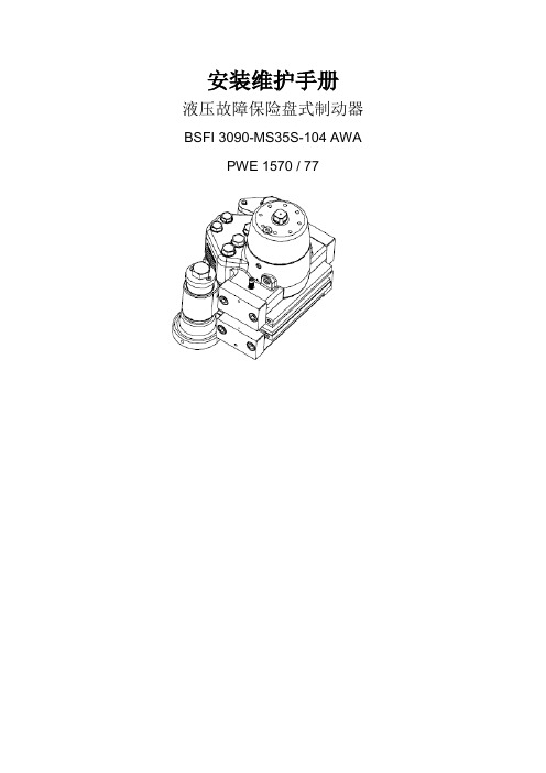
安装维护手册液压故障保险盘式制动器BSFI 3090-MS35S-104 AWA PWE 1570 / 77目录1. 概述 (4)1.1 联系人 (4)1.2 安全 (4)1.3 此手册中的常规惯例 (6)1.4 弃权声明 (7)1.5 换算系数 (7)1.6 铭牌/序号 (8)1.7 制动器是如何工作的。
(10)1.8 功能 (11)1.9 运输 (12)1.10 接口 (13)1.11 润滑 (15)1.12 存放 (16)1.13 处理 (16)1.14 如何采购备件 (17)2. 安装 (17)2.1 吊升和装卸 (17)2.2 清洁制动盘 (17)2.3 清洁安装表面 (18)2.4 装卸/安装制动瓦片 (18)2.5 安装制动器 (21)2.6 检查间隙 (26)2.7 检查制动器的对中调整 (26)2.8 定位系统 (27)2.9 调整定位系统 (29)2.10 制动钳排气和冲洗 (32)2.11 安装指示器 (33)2.12 研磨 (34)2.13 拆下制动器 (35)3. 维护 (37)3.1 指示器 (37)3.2 更换制动瓦片 (37)3.3更换其他部件 (40)3.4 拆下主动制动钳 (41)3.5 更换密封件 (42)3.6 检查弹簧组 (51)3.7 更换弹簧组 (53)3.8 制动器的润滑 (56)4.故障查找 (56)附件A-尺寸图 (60)附件B-装配图,制动器 (61)附件B-装配部件清单,制动器 (62)附件C-备件图,半个制动钳分解图 (64)附件C-备件图,半个制动钳 (65)附件C-备件清单,半个制动钳 (66)附件D-备件图,被动制动钳 (67)附件E-安装图 (68)附件F-定位系统 (69)附件G-“开/关”和“没有调节”指示器 (71)附件H-“瓦片磨损”指示器 (73)附件I-技术参数 (74)附件J-建议使用的流体 (76)附件K-推荐备件 (78)1.概述Svendborg Brakes公司拥有广泛且完整的产品范围,可以为制动器设计者提供了一系列的制动装置,这些装置可以满足关于强大制动的安全性和可靠性以及多用途制动的最高要求。
潘基斯汽车零件维护指南说明书
IndexAccessoriesInstallation.................................... 97ACCESSORY (Ignition KeyPosition)........................................ 47AddingAutomatic TransmissionFluid........................................ 139Brake Fluid................................. 141Clutch Fluid................................ 142Engine Coolant........................... 133Engine Oil................................... 128Manual Transmission Fluid ..... 140Power Steering Fluid................. 143Windshield Washer Fluid......... 138Additional Safety Information........ 16Door Locks................................... 16Driving with Pets......................... 17Seat-back Position........................ 16Storing Cargo Safely................... 17Additives, Engine Oil..................... 130AdjustmentsMirrors.......................................... 60Seats.............................................. 50Steering Wheel. (42)Airbag (SRS).................................... 10Air Cleaner Element...................... 144Air Conditioning............................... 68Maintenance............................... 153Usage............................................. 68Air Outlets (Vents).......................... 70Air Pressure, Tires........................ 156High Speed Driving................... 203Normal Driving.......................... 156Alcohol and Drugs........................... 25Alcohol in Gasoline.......................... 90Aluminum Wheels, Cleaning........ 171Antifreeze....................................... 133Anti-lock Brakes (ABS)Description................................. 111Indicator Light.................... 34, 113Operation.................................... 112Anti-theft Steering Column Lock .. 46Appearance Care........................... 169Ashtray.............................................. 64Audio System................................... 76Automatic Speed Control................ 43Automatic Transmission............... 104Capacity, Fluid........................... 200Checking Fluid Level................ 139Shifting. (106)Shift Lever Position Indicator.. 104Shift Lever Positions................. 104Shift Lock Release (108)BatteryCharging SystemIndicator............................32, 189Jump Starting............................. 184Maintenance............................... 148Specifications............................. 201Before Driving................................. 89Belts, Seat........................................... 5Beverage Holder.............................. 63Body Repair.................................... 174BrakesAnti-lock System (ABS)............ 111Break-in, New Linings................. 90Fluid............................................ 141Light, Burned-out...................... 165Parking.......................................... 61System Indicator.......................... 32Wear Indicators. (110)CONTINUEDIndexBrakes, ABSDescription................................. 111Operation.................................... 112System Indicator..................34, 113Braking System.............................. 110Break-in, New Car........................... 90Brightness Control, Instruments... 39Brights, Headlights......................... 38Bulb ReplacementBack-up Lights........................... 165Brake Lights............................... 165Front Parking Lights................. 164Front Side Marker Lights......... 164Headlights.................................. 162Interior Light.............................. 166License Plate Lights.................. 166Rear Side Marker Lights.......... 165Specifications............................. 201Trunk Light................................ 166Turn Signal Lights..................... 164Bulbs, Halogen. (162)Cables, Jump Starting With.......... 184Capacities Chart.. (200)Carbon Monoxide Hazard.............. 26Cargo, Loading................................. 98Cassette PlayerCare............................................... 83Operation...................................... 81CAUTION, Explanation of............... ii CD Changer...................................... 84Certification Label......................... 198Chains............................................. 161Change OilHow to......................................... 130When to....................................... 122Changing a Flat Tire ..................... 177Changing Engine Coolant............. 135Charging System Indicator....32, 189CheckingAutomatic TransmissionFluid........................................ 139Battery Condition...................... 148Brake Fluid................................. 141Clutch Fluid................................ 142Drive Belts.................................. 155Engine Coolant........................... 133Engine Oil................................... 128Fuses........................................... 192Manual Transmission Fluid .. (140)Power Steering Fluid................. 143Checklist, Before Driving............. 100Child Safety...................................... 18Cigarette Lighter............................. 64Cleaner, Air.................................... 144CleaningAluminum Wheels..................... 171Carpeting.................................... 172Exterior....................................... 170Fabric.......................................... 172Interior........................................ 172Seat Belts.................................... 172Vinyl............................................ 172Windows..................................... 173CLEAN Light................................... 83Clock, Setting the ............................ 62Clutch Fluid.................................... 142Code, Audio System........................ 88CO in the Exhaust......................... 206Cold Weather, Starting in............. 101Compact Spare............................... 176Consumer Information*................ 210Controls, Instruments and..............29IndexCoolantAdding......................................... 133Checking....................................... 95Proper Solution.......................... 133Replacing.................................... 135Temperature Gauge.................... 36Corrosion Protection..................... 173Crankcase Emission ControlSystem......................................... 205Cruise Control Operation............... 43Customer Relations Office.. (210)DANGER, Explanation of................. ii Dashboard........................................ 30Daytime Running Lights................. 38Dead Battery, What to Do............ 184Defects, Reporting Safety............. 213Defogger, Rear Window................. 41Defrosting the Windows................. 73DEXRON® III AutomaticTransmission Fluid.................... 139Dimensions..................................... 200Dimming the Headlights. (38)DipstickAutomatic Transmission........... 139Engine Oil................................... 128Directional Signals........................... 39Disabled, Towing Your Car If...... 196Disc Brake Wear Indicators......... 111Disposal of Used Oil...................... 131DoorsLocking and Unlocking............... 47DOT Tire Quality Grading........... 203Downshifting, 5-speed ManualTransmission.............................. 102Drive Belts...................................... 155Driving.............................................. 99Economy....................................... 96In Bad Weather.......................... 114In Foreign Countries. (91)Economy, Fuel................................. 96Emergencies on the Road............. 175Battery, Jump Starting.............. 184Changing a Flat Tire................. 177Charging System Indicator...... 189Checking the Fuses. (192)Low Oil Pressure Indicator...... 188Malfunction Indicator Lamp.... 190Overheated Engine................... 186Emergency Brake............................ 61Emergency Flashers....................... 41Emission Controls......................... 205EngineCoolant Temperature Gauge ..... 36Malfunction IndicatorLamp............................... 33, 190Oil Pressure Indicator....... 32, 188Oil, What Kind to Use............... 129Overheating................................ 186Specifications............................. 200Ethanol in Gasoline ......................... 91Evaporative Emission Controls.... 205Exhaust Fumes................................ 26Expectant Mothers, Use of SeatBelts by........................................... 9Exterior, Cleaning the. (170)Fabric, Cleaning (172)CONTINUEDIndexFan, Interior...................................... 68Features, Comfort andConvenience................................. 67Filling the Fuel Tank....................... 92FiltersAir................................................ 144Oil................................................ 130First Gear, Shifting........................ 1075-speed Manual TransmissionChecking Fluid Level................ 140Shifting the................................. 102Flashers, Hazard Warning.............. 41Flat Tire, Changing a.................... 177FluidsAutomatic Transmission........... 139Brake........................................... 141Clutch.......................................... 142Manual Transmission............... 140Power Steering........................... 143Windshield Washer...................138FM Stereo RadioReception...................................... 79Foreign Countries, Driving in........ 91Four-way Flashers........................... 41Front End, Towing byEmergency Wrecker (196)Fuel.................................................... 90Fill Door and Cap......................... 92Gauge............................................ 36Octane Requirement................... 90Oxygenated.................................. 90Reserve Indicator......................... 33Tank, Filling the........................... 92Fuses, Checking the. (192)Gas Mileage, Improving.................. 96Gasohol............................................. 91Gasoline............................................ 90Fuel Reserve Indicator................ 33Gauge............................................ 36Octane Requirement................... 90Tank, Filling the........................... 92Gas Station Procedures................... 92GaugesEngine Coolant Temperature .... 36Fuel................................................ 36Gearshift Lever PositionsAutomatic Transmission........... 1045-speed ManualTransmission (102)Glass Cleaning............................... 173Glove Box.. (61)Halogen Headlight Bulbs.............. 162Hazard Warning Flashers............... 41HeadlightsDaytime Running Lights............. 38High Beam Indicator................... 34High Beams, Turning on............ 38Low Beams, Turning on............. 38Reminder Beeper......................... 38Replacing Halogen Bulbs ......... 162Turning on.................................... 38Heating and Cooling........................ 68High Altitude, Starting at.............. 101High-Low Beam Switch .................. 38Hood, Opening the .......................... 93Horn................................................... 37Hot Coolant, Warning about........ 133Hydraulic Clutch............................ 142Hydroplaning..................................115Index Identification Number, Vehicle (198)If Your Car Has to be Towed (196)IgnitionKeys (45)Switch (46)Timing Control System (206)Indicator Lights, InstrumentPanel (31)Infant Restraint (20)Inflation, Proper Tire (156)High Speed Driving (203)Normal Driving (156)Inside Mirror (60)Inspection, Tire (157)Instrument Panel (30)Instrument Panel Brightness (39)Interior Cleaning (172)Interior Light (65)Introduction (i)Jacking up the Car (179)Jack, Tire (178)Jump Starting (184)Keys (45)Label, Certification (198)Lane Change, Signaling (39)Lap/Shoulder Belts (6)Leaking of Exhaust into Car (26)Lighter, Cigarette (64)LightsBulb Replacement (162)Indicator (31)Parking (38)Turn Signal (39)Loading Cargo (98)LOCK (Ignition Key Position) (46)LocksAnti-theft Steering Column (46)Fuel Fill Door (92)Power Door (48)Rear Locking Compartment (50)Trunk (48)Maintenance (117)Owner Maintenance Checks (126)Record.................................. 124-125Safety (118)Schedule.............................. 120-123Malfunction Indicator Lamp..33, 190Manual Transmission (102)Manual Transmission Fluid (140)Maximum Shift Speeds........ 103, 107Meters, Gauges (35)Methanol in Gasoline (91)Mirrors, Adjusting (60)CONTINUEDLow Coolant Level (133)Low Fuel Indicator (33)Lower Gear, Downshifting to a (102)Low Oil Pressure Indicator....32, 188Lubricant Specifications Chart (200)Luggage............................................98。
信赖安全的刹车维修指南说明书

INFORMATION ON BRAKE REPAIRSRELIANCE. TRUST. PERFORMANCE.Safety first!1. The brake system is a safety system.Repair work on the brake system should only be carried out by trained specialists.2. Use only spare parts that are 100% compatible with the brake systemof the vehicle.3. Use only approved brake pads and brake discs.4. Observe the assembly manuals and the respective, vehicle-specific repairinstructions.The basics of professionaldisc brake repairThe following should always be observed!1. Before installation, compare the new spare parts with the parts you haveremoved.2. Brake discs should always be replaced in pairs and always together withnew brake pads.3. Before mounting a new brake disc, the wheel hub should be metallicallybright, flat, and free from burrs. It must then be preserved using a suitable spray oil.4. A proper repair includes the replacement of all accessory parts, such asguide plates or screws. Please always use all parts provided.5. Brake caliper shafts must be clean and rust-free, and the brake caliperguides must run smoothly.6. Use only metal-free brake paste on the contact points between the brakepad and brake caliper. Avoid excessive greasing.7. Components should be clean, should operate smoothly, and should begreased correctly in order to guarantee that the brake system functions properly and to prevent unnecessary noise.8. In order to prevent damage to the wheel suspension or wheel hub, roughmechanical handling must be avoided when removing and installing brake components.9. For correct assembly, always use brake-specific tools or, if necessary,special tools. Observe the prescribed tightening torques!10. Since new brake discs and brake pads first need to adjust to one another,the brake system must be run in immediately following the repair. Comply with the vehicle manufacturers’ run-in instructions!Brake pad structure1. Steel pad base plateThe pad base plate is individually adapted to the requirements of the respective brake system with regard to the quality, strength, and tolerance.Its task is to dissipate temperature and to guide the pad in the brake caliper. A powder coating enables the base plate to be given reliable corrosion protection. 2. Lining adhesiveSpecially developed adhesives with a phenol resin base permanently join the brake pad to the base plate and ensure a high shearing strength.3. Intermediate layerThe intermediate layer, also known as an underlayer, ensures the adhesion between the friction material and the adhesive. This improves the hardness, minimises the risk of cracking, and adds to the comfort features of the brake pad in general.4. Friction materialThe friction material has a very demanding job to do, and is therefore precisely tailored to meet the needs of the respective field of application.1345255765. Secondary measureVarious damping measures, or secondary measures, can be implemented on the brake pad in order to eliminate vibration noise. In addition to the familiar damping plates, a damping lacquer coating may also be used or a special modification may be made to the friction material.6. Wear indicatorWear indicators are monitoring devices for detecting when the brake pads need to be replaced. Mechanical displays are riveted onto the base plate. Electronic wear indicators are embedded in the friction material as an additional sensor.7. MarkingFor clear identification, the approved brake pads are marked with an imprint on the rear of the base plate. This ensures that it is always possible to determine where, when, and by whom the brake pad was manufactured.2564131. ECE number2. PA4029GFPA (manufacturer) 4029 (material key)GF (US friction value code)3. Hella Pagid part number 4. Hella Pagid batch number- defines the unique product composition 5. Environmental code6. Part number/technical information numberBrake pad markingSecondary measuresBraking noise is caused by friction value fluctuations during braking. Secondarymeasures are intended to suppress high-frequency vibrations and thereforeprevent noise. These measures can vary from vehicle to vehicle depending onthe structure of the brake system. In some brake pads, several measures maybe used simultaneously.Additional noise-damping measures on the rear of the base plate.These include a lacquer coating, textile surface, adhesive film, or additionaldamping plate.➔These measures and features further improve the braking effect anddriving comfort➔Adhesive film also secures the brake pad in its operating position andprevents misalignments and noiseBrake pad with adhesive filmChamfersChamfers are tapers in the friction surface individually developed for each brake pad. The final contour of the chamfer is determined through extensive driving tests as well as on test stands.Task➔To improve the transition between the brake pad and brake disc • Sharp edges are avoided➔To reduce vibrations and noise when initiating the braking process • By altering the contact surface on the brake disc, the pressure on thebrake pad is increased even at low speedsWeights on the brake padAn additional weight mounted on the brake pad increases the overall mass and thus reduces the resonant frequency of the component.Depending on the design and positioning of the weight, the resulting vibration damping can reduce noise in a targeted manner or eliminate it altogether. The design of the weight may vary depending on the vehicle manufacturer and thebrake system.Slots in the brake padDepending on the size and shape of the brake pad, cracks may form in the friction lining as a result of temperature-dependent expansion.Slots are milled into some brake pads in order to prevent these cracks. These also reduce noise and hold brake pad wear particles.Directional brake padsThese brake pads are adapted to the installation position in the brake caliper and the running direction of the brake disc through special secondary measures such as chamfers or damping plates.A crescent-shaped recess on the rear alters the press-on position of the piston-side brake pad. This reduces noise and improves the comfort characteristics. The running direction is indicated by an arrow. Special installation instructions are provided for the respective brake pads.Damage patterns ofdisc brake padsSeparation of the brake padThe brake pad is coming away from the base plate Cause:➔Thermal overload➔Underlying rust➔Base plate warped due to inaccurate fit or assembly faultThermal overloadBrake pad damaged by overheating.The binding agents in the pad are destroyed and the brake pad material cracks. Cause:➔Jammed or stuck brake pad➔Jammed or stuck guide sleeve➔Brake caliper piston is stiff➔Extreme driving patterns or continuous brakingprocessingThe brake pad has been mechanically altered.The subsequent processing of a brake pad, for example modifying the brake pad contour or the base plate, is not permitted. Unauthorised modifications to the brake pad result in altered braking characteristics and, in extremecases, may lead to failure of the wheel brake.Worn patches and scoringThe surface of the brake pad exhibits marked scoring and worn edges. Cause:➔New pads were mounted on old, worn brake discs➔Foreign body between the brake pad and the disc➔Environmental influences (salt, dirt, etc.)Material or edge breaks The brake pad has broken out at the edges. Cause:➔Thermal overload➔Faulty assemblyExcessive wearBrake pads are worn down to the base plate. Cause:➔Inadequate maintenance➔Inspected too infrequently➔Continuous braking on descentsFaulty assemblyAssembly instructions not observed.The adhesive film on the back was not removed prior to assembly. Furthermore, the film has been needlessly greased with brake paste. This installation error leads to the brake pad being positioned incorrectly in the brake caliper, resulting in noise and premature wear.Damage patterns ofbrake discsOverheated brake discJudder marks.Cause:➔Thermal overload in the break-in phase➔Violent or sudden brakingEffects:➔Noise and vibrations when braking from high speedsBrake disc discoloured from standingCause:➔Brakes used too infrequently➔Leaving the vehicle parked for long periods and environmental influences cause corrosion and surface changes of the friction ringEffects:➔Braking noises➔Signs of judderingNon-uniform thickness of friction ringCause:➔Faulty or unclean assembly of the brake disc on the wheel hub➔Contact surface on the wheel hub not properly cleaned Effects:➔Wobbly movement of the brake disc➔Disc runout when braking only slightly➔Juddering when coldBrake disc with scoringCause:➔Overloading➔Effects of dirt➔Poor-quality brake padEffects:➔Reduced braking effect➔Noise➔Increased wearBrake disc with severe heat cracksCause:➔Mechanical alternating loads➔Thermal overloadRust underneath the contact face of thebrake disc chamberCause:➔Faulty assembly➔Wheel hub not properly cleanedEffects:➔Non-uniform thickness➔Lateral runoutCracks near the disc chamberCause:➔Wrong torque➔Faulty assemblyEffects:➔Reduced stability➔Noise➔Steering wheel flutterProfessional inspection ofthe brake systemBrake fluidCheck the brake fluid level at the expansion tank.➔The display should be between MIN and MAX.A low fluid level may indicate a brake system leak or worn brake pads. Only use new brake fluid that has been approved for the vehicle type!➔Check: Wet boiling point, water content critical (>3%) Change intervals:Every 24 months. Observe the vehicle manufacturer's maintenance specificationsBrake padBefore installing new brake pads, a visual check of the removed brake pads should first be carried out.Check the brake pad for exterior damage:➔Check the surface structure of the friction lining for cracks or joints➔Check the pad base plate for deformation or jammingCheck the contact patterns of the friction surfaces for wear:➔The wear pattern may indicate further possible faults in the brake system Wear limit:➔Brake pad (friction lining): At least 2-3 mmAlways observe the wear limit of both brake pads on one wheel side!Observe the vehicle manufacturer's wear specifications!Brake pad wear indicator➔Check the wear indicator and wiring for correct position and function➔Check the wiring and connectors for damage and correct position➔The wear indicator must be replaced with new brake pads!Brake disc➔Check the friction surfaces for scoring, wear, and corrosion.➔Check the minimum strength, thickness difference, and lateral runout of the brake disc.➔Minimum thickness: The MIN TH- value (mm) is stamped onto the disc.➔Disc runout: Max. 0.07 mm.➔Friction ring thickness difference: Max. 0.012 mm.You must always observe the model-specific technical specificationsof the vehicle manufacturer!Wheel hub➔Check the surfaces for damage and corrosion.➔Check the concentricity of the wheel hub.➔Check the lateral runout of the wheel hub: Max. hub runout: 0.03 mm. The contact faces must be clean, rust-free, and metallically bright!Do not grease the contact faces! A faulty wheel bearing or impermissible wheel bearing play can lead to uncomfortable braking characteristicsof the vehicle.Brake caliperCheck that the mechanical components of the brake caliper are functioningproperly:➔Check the brake pad guides and caliper guides for contamination, damage, and corrosion.Check that the hydraulic components of the brake caliper are functioning properly:➔Check that the pistons move easily: Jammed pistons result in faulty play and thus to overheating of the brake pads.➔Check the dust protection boot of the brake piston for damage: Faulty collars lead to corrosion of the piston and the bore hole.Check the guide bolts for ease of movement; check the protective plug and damping sleeves for damage:➔Faulty components result in unwanted noise, incorrect wheel brake function, and premature or uneven brake pad wear.During a repair, it is recommended to also replace the brake pad accessory kit!Wheel suspension and wheelsDuring the brake repair, it is recommended to also check the components in the area of the wheel brake, such as the wheels, threads, wheel bolts, steering, and axle suspension.Components that are damaged or not functioning properly have an effect on the braking characteristics.Inspection on brake test standaccordance with the EC directive.➔Braking force of service brakeFront axle: Max. difference 25%➔Braking force of service brakeRear axle: Max. difference 25%➔Braking force of parking brakeManual operation: Max. difference 50%be observed!Assembly instructionsThe assembly instructions and notes included in the packaging must always be followed!These contain special instructions, for example:➔Safety instructions for repair work on an electro-hydraulic brake system. ➔Directional disc brake pads.➔Disc brake pads with removable film on the backplate.Observing the installation instructions helps to prevent assemblyfaults and complaints!HELLA PAGID fluids – A greatproduct rangeOPTIMUM BRAKING PERFORMANCE. MAXIMUM SAFETY.EASY CARE AND MAINTENANCE.The comprehensive range of brake fluids from HELLA PAGID offers brake fluids that can be used individually for all conventional brake systems: DOT 3, DOT 4, DOT 4 LV, DOT 5.1, LHM. HELLA PAGID brake fluids are available in a range of container sizes.The brake fluid product range from HELLA PAGID is appropriately supplemented with brake cleaner and mounting paste.The brake cleaner from HELLA PAGID attracts brake dust and is a reliable means of removing oil, grease, dirt, and brake fluid – and it leaves no residue. In order to ensure safe functioning in the long term, the wheel brake must undergo regular maintenance. During maintenance, all mechanical parts should be greased with a temperature-resistant, non-metallic, permanent lubricant.The reprinting, distribution, reproduction, exploitation in any form and disclosure of the contents of this document, even in part, is prohibited without our express written approval and indication of the source. The case examples illustrated in this document are for demonstration purposes only and do not claim to be complete.HELLA Automotive 5CNGU +PE 201 Kelly DrivePeachtree City, GA 30269 1.877.224.3552 *******************© Hella Pagid GMBH, EssenJ01314/02.18。
Sure-Stop RB500 RB625 绳索制动器安装和维护手册说明书
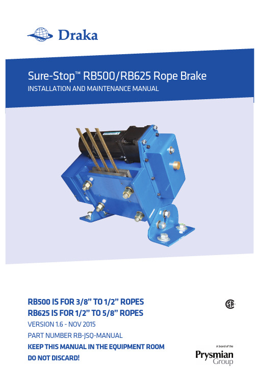
RB500 IS FOR 3/8” TO 1/2” ROPESRB625 IS FOR 1/2” TO 5/8” ROPES VERSION 1.6 - NOV 2015PART NUMBER RB-JSQ-MANUALKEEP ThIS manual In ThE EquIPmEnT ROOmDO nOT DISCaRD!ContentsDescription Page Introduction and Operational Overview 2 Certifications 2 Technical Specifications 3 Inspection 4 Packing List 4 Required Tools for Installation 4 Safety Considerations 4 Mechanical Installation 5 Electrical Installation 8 Maintenance 9 Manual Brake Release 9 Replacement Parts 9 Drawings 101Introduction and Operational OverviewThank you for purchasing the Sure-Stop™ Rope Brake from Draka. When properly installed and maintained, this product will provide years of reliable service.The patented Sure-Stop Rope Brake offers clear improvements in rope brake safety and operation:It’s a single-piece design; no separate hydraulic unit is required for operationIts compact footprint (16.3 in x 9.2 in for the RB500, 18.0 in x 9.2 in for the RB625) and height (13.2 in for the RB500 and 13.6 for the RB625) installs easily in tight spacesA simple five-wire hookup (two for power, two for controller, one for ground)eases installationCertified to CSA B44.1-04 and ASME-A17.5-2004 (cCSAus)Complies with all ASME A17.1-2007 code requirementsPlease follow the instructions throughout this manual to ensure the safety of passengers and all installation/maintenance personnel.CertificationsSure-Stop Rope Brakes are certified to CSA B44.1/ASME A17.5 and has been verified to meet all relevant ASME A17.1 code requirements. It has also been tested and certified by NETEC (National Elevator Inspection and Testing Center) report number T3-F35-09-009.Sure Stop Rope Brakes are covered under US patent 8,256,579 B2.2Technical SpecificationsRope Diameter 3/8 in to 1/2 in • 9.5 to 12.7 mm 1/2 in to 5/8 in • 12.7 to 16 mm Brake Pad Width 6 in • 152 mm 7.75 in • 197 mm Maximum Rope Spread 5.25 in • 145 mm 7.75 in • 197 mmExternal dimensions 16.25 x 8.625 x 13.2 in 18.0 x 9.125 x 13.2 in413 x 219 x 335 mm 457 x 232 x 335 mm Mounting hole dimensions 13.5 x 5.6 in • 344 x 142 mm 15.375 x 6.0 in • 391 x 152.4 mm Weight 120 lbs • 55 kg 160 lbs • 72.7 kgRotation angle up to 45 degrees up to 45 degreesMotor 120W/180W, 220VAC +/-10%, 120W/180W, 220VAC +/-10%,6A, 50/60 Hz 6A, 50/60 HzReduction rate 1:25, 1:30, 1:36 1:25, 1:30, 1:36Torque of output shaft (max) 300 kg-cm 300 kg-cm Electromagnetic brake parameter 24V, 0.5A 24V, 0.5A1:1 Roping Rated Speed 500 ft/min • 2.5 m/sec 1,200 ft/min • 6.0 m/sec1:1 Rated Load (max) 5,500 lbs • 2,500 kg 7,500 lbs • 3410 kg1:1 Rated Load (min) 440 lbs • 200 kg 1,900 lbs • 863 kg1:1 Total System Mass (max) 16,000 lbs • 7,250 kg 30,000 lbs • 13636 kg1:1 Total System Mass (min) 1,985 lbs • 900 kg 5,500 lbs • 2,500 kg2:1 Roping Rated Speed 350 ft/min • 1.75 m/sec 600 ft/min • 3 m/sec2:1 Rated Load (max) 11,000 lbs • 5,000 kg 15,000 lbs • 6818 kg2:1 Rated Load (min) 880 lbs • 400 kg 4,000 lbs • 1818 kg2:1 Total System Mass (max) 28,400 lbs • 12,900 kg 61,000 lbs • 27727 kg2:1 Total System Mass (min) 2,820 lbs • 1,280 kg 11,000 lbs • 5000 kg34Prior to installationInspectionInspect the shipping container and contents upon receipt.DO NOT install the brake if you suspect it has been damaged during shipping.Packing ListThe Sure Stop rope brake kit includes the following:RB-JSQ8 or RB-JSQ9 Sure-Stop Rope Brake - RB-JSQ8 is the RB500, RB-JSQ9 is the RB625 RB-JSQ-CABLE Power/Signal Cable RB-JSQ-MANUAL Installation ManualRequired Tools and Hardware (not included)24 mm wrench Wire strippers Flathead screwdriverMounting bolts - Four (4) M16 x 2 Class 10.9 or 5/8 in Grade 8 bolts are required for mounting the rope brake to the machine frame. Observe all recommended torque requirements:M16 x 2 Class 10.9 bolts - 310 n-m 5/8 in Grade 8 bolts - 220 ft-lbsSafety ConsiderationsEnsure that all power has been disconnected prior to installation of this device; all lockout/tag-out procedures should be observed.Observe all safety instructions contained in this manual during the installation of this product.DO NOT put your fingers between the plates -severe injury may result.Installation ConsiderationsDraka Sure Stop Rope Brakes may be mounted in any position as long as the installation requirements in the mechanical installation section are met. Wherever you choose to install the unit, make certain there is access to manually open it. There will need to be a minimum clearance of 9 in • 228 mm at the side of the unit where the power wire plugs in.5Mechanical installationPrior to installation, confirm that the structure to which the rope brakes are to be mounted can withstand the pull force generated by an event. For the RB500, the pull force is 4600 lbs - for the RB625, the pull force is 5800 lbs.Step 1Use the dimensions provided on the template on page 10 to mark the mounting hole loca-tions on the machine frame for the rope brake. It may be helpful to temporarily place the rope brake in position. Drill four mounting holes to accommodate the selected fastener.DO nOT put your fingers between the plates - severe injury may result.Pull the pointer out. Push it toward the ‘locked’ position as far as you can while keeping light pressure on it. FIRMLY turn the crank handle in the direction shown by the arrow on the motor housing.Step 3 >Loosen and remove the four (4) M16 x 1.5 nuts and washers that secure the outer (moving) plate. Remove the outer plate.unlockedlockedpointer6Step 4 >Loosen but do not remove the four (4) bolts connecting the right and left support legs to the brake assembly. This will allow you to tilt the rope brake to match the angle of the ropes as they pass through the plates.Step 5 >Place the rope brake assembly on the machine frame where you have drilled the mounting holes. Tilt the brake so that the inner (fixed) plate matches the angle of the ropes.NOTE: The ropes must be parallel to each other. If necessary, use a rope block to move the ropes.Step 6 >Using the hardware specified in the “Required Tools and Hardware” section, loosely attach therope brake to the machine frame.7Step 7 >Angle the rope brake assembly so that the inner (fixed) plate lightly touches the ropes for its entire length. (You may need to shift the position of the rope brake on the machine frame to permit full and correct contact.) Step 8Tighten the bolts that tilt the rope brake (loosened in Step 4) to a torque of 149 N-m • 110 ft-lb. Secure the rope brake assembly to the machine frame (attached in Step 6) to the torques listed on page 4.are tightened to a torque of 110 ft-lb • 149 N-m. It is typical for one pad to have slightly deeper grooves than the other. The pads and ropes should look like this. >Note: Replace the pads when the pad depth (measured from the groove crown to the back of the plate) measures 0.10 in • 2.5 mm. Pad wear varies depending on rope size, car speed, and total system mass. If the rope brakeis ever activated, inspect the pads for wear.8Electrical installationStep 1Make sure that all power has been disconnected and all circuitry locked-out.Step 2Connect the power/signal harness to the elevator controller. If 220VAC power is not available, use a 120/240VAC step-up transformer as shown in Optional Transformer Wiring below:Conductor No. Remark 1 Power 2Neutral3 and4 Securely connect wires 3 and 45 and6 Signal from controller passing through lower limit switch monitoring brake status 7GroundConnect the other end of the power/signal harness to the rope brake.Step 4 >Power up the rope brake. If the rope brake has been installed properly, the brake will be in the open position with the switch on and in the closed position with the switch off.Depending on the diameter of the hoist ropes used, the limit switch located at the bottom of the brake may require adjustment. The limit switch contacts are closed when the brake jaws are opened.To adjust the limit switch, allow the brake to close on the hoist ropes and adjust the set screw inward until the limit switch opens.9MaintenanceManual ReleaseIn certain instances, it may be necessary to open the brake manually. After confirming that the unit is powered off, follow Step 2 on page 5.Spare PartsContact Draka customer service for pricing and availability of spare parts. The toll-free number in the US and Canada is 1-877-DRAKA-EP (1-877-372-5237).WarrantyThe Sure-Stop rope brake carries a one-year warranty against defects in material and work-manship. Warranty is limited to US and Canadian customers only. A valid proof of purchase from Draka is required for any warranty claims.Failure to comply with any of the instructions or warnings outlined in this installation and maintenance manual will void all warranty claims10Rope Brake FootprintsRB500sideRB625sideFor technical assistance, call toll free (US and Canada)877.408.HELP (877.408.4357)To order kits/parts,call toll free 877.DRAKA EP (877.372.5237)R B -J S Q -M A N U A L 1115Draka Elevator2151 N. Church Street | Rocky Mount, NC 278041-877-DRAKA EP (877-372-5237)+1-252-984-5100 | Fax +1-252-972-6001Technical information 1-877-408-4357。
制动器控制装置安装和维护手册(低温)MEH-1010-0137-80 3
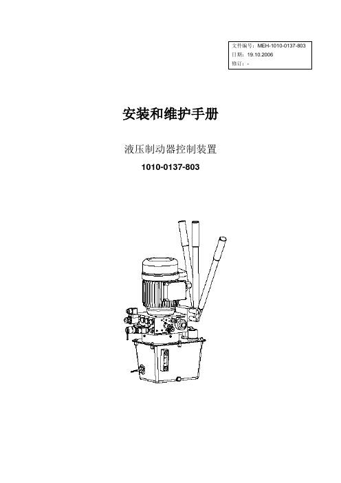
安装和维护手册液压制动器控制装置1010-0137-803安装和维护手册- 1010-0137-803目录1.概述 (1)1.1联系人 (1)1.2安全 (1)1.3常规表示法 (1)1.4否认声明 (2)1.5运输 (2)1.6吊装 (2)1.7存放 (3)1.8订购备件须知 (3)2.安装和调试 (3)2.1安装 (3)2.2连接 (3)2.3启动泵站前的工作 (3)3.液压系统说明 (4)3.1综述 (4)3.2功能 (4)3.3液压原理图 (1)4.维护 (2)4.1检查 (2)4.2调整 (2)4.3故障检查 (2)4.4功能检查 (3)4.5拆卸泵站 (3)4.6换油 (3)4.7换油,清理油箱 (3)4.8 更换滤油器 (4)4.9更换通气阀 (4)4.10测量气体压力 (5)4.11蓄能器重新充气 (6)5. 排除故障 (7)5.1故障简介 (7)5.2泵站无法卸压 (8)5.3 泵站不能设定/升高压力 (9)5.4其他故障 (10)附录A-尺寸图 (11)附录B-备件图 (12)附录B-备件清单 (13)附录C-液压设定值 (14)附录D-调整 (15)附录E-电气图纸 (17)附录F-推荐使用的液体 (18)附录G-推荐的备件 (20)1. 概述感谢购买Svendborg制动器产品。
使用此产品前请仔细阅读本手册。
1.1联系人如果对本手册有任何疑问,请联系您当地的Svendbor制动器代表处或距离最近的Svendborg制动器公司办事处。
Svendborg制动器公司办事处:丹麦:Jernbanevej 9, DK-5882 Vejstrup电话+45 63 255 255e-mail:sb@svendborg-brakes.dk德国:Kirchnerstrasse 42, DE-32257 Bünde电话+49 522 368 540-0e-mail:sb@svendborg-brakes.de西班牙:C/ San Benito 24, 1ºB, ES-42001 Soria电话:+34 975 233 655e-mail:sb@svendborg-brakes.es美国:P.O. Box 1948, Denver, CO 80201-1948 电话:+1 303 285 1271e-mail:sb@或访问我公司网站:1.2安全Svendborg制动器公司的产品系列适用于安装在旋转制动盘上,用于停机制动,工作制动或紧急制动。
旺威汽车维修指南说明书

Understanding Volkswagen Driver Assistance SystemsAn on-board computer requires 0.25 seconds or less to reactto an impending danger. A person only overcomes theirsurprise and reacts after about a one-second delay.DramatizationDramatizationTechConnect Feature ArticleToday’s Volkswagen vehicles are available with many systems to enhance drivers’ experiences on the road. Some systems, like windshield wipers, are considered basic. Other systems, like ABS and traction control, are more advanced. But the next level of driver assistance features is here. An on-board computer requires 0.25 seconds or less to react to an impending danger. A person only overcomes their surprise and reacts after about a one-second delay.These advanced driver assistance systems can not only help alert the driver to an impending collision, but can also intervene to help avoid them altogether. Vehicles can brake to avoid a collision, and caneven park itself. It may seem like these features would be reserved for the most high-line cars in the fleet. But even the Golf and Golf SportWagen are available with many of the latest Volkswagen Driver Assistance systems.Before any type of testing or diagnosis of a system can occur, we must understand how each system works. This is vital when working on new available Driver Assistance systems. If we don’t understand how a system should work, we will not be able to properly identify an issue with a system. Where To StartWhen it comes to available Driver Assistance systems, the components vary from system to system. Let’s start by identifying each available feature.Automatic Post-Collision BrakingThe Automatic Post-Collision Braking system that results in an airbag deployment can automatically brake, slowing the vehicle down after an initial collision. This system is designed to lessen the severity of a secondary impact. Automatic Post-Collision Braking can slow the vehicle to a speed of 6 mph, and can be overridden by accelerating or hard braking. Available on:• 2015: Golf, GTI, Golf R, e-Golf, Golf SportWagen, Touareg• 2016: Golf, GTI, Golf R, e-Golf, Golf SportWagen, Jetta TSI, Jetta GLI/Hybrid, Beetle, BeetleConvertible, Touareg, PassatAdaptive Cruise Control (ACC)Adaptive Cruise Control functions very much like traditional vehicle cruise control. The speed is set by the driver, and the vehicle is designed to maintain that set speed. A vehicle equipped with ACC can also regulate speed based on the speed of other vehicles ahead. If a vehicle is detected ahead, the car will attempt to keep a consistent set distance from the other vehicle. Adaptive Cruise Control can accelerate on its own to the maximum set speed, and can brake automatically if the vehicle in front slows down. Available on:• 2015: Touareg• 2016: Golf, (manual transmission) GTI (manualtransmission), Golf R (manual transmission), Golf SportWagen (manual transmission) , Jetta TSI/TDI (automatic/DSG) Passat (automatic/DSG) Adaptive Cruise Control (ACC) with Follow to StopMuch like Adaptive Cruise Control, ACC with Follow to Stop can regulate the vehicle speed. In additionto speed and distance regulation, ACC with Followto Stop can bring the vehicle to a complete stop in normal traffic flow. Pressing the accelerator pedal, orusing the Resume function on the ACC control leverMid-Range Radar Sensor, 2015 Jetta The ACC system identifies the vehicles in front. V8 N1 Spring 201626Driver Assistance Systemson CC will resume ACC based on the distance from the vehicle in front.Available on:• 2015: Touareg• 2016: Golf, (automatic/DSG), GTI (DSG), Golf SportWagen (automatic/DSG), Touareg Sensors used:• Front Long-Range and Mid-Range RadarsForward Collision WarningVehicles with Forward Collision Warning can help to monitor the distance to traffic ahead. The system helps warn the driver of critical front-end collision situations. An audible alert and a visual warning are displayed in the MFI display.Available on:• 2015 Golf, GTI, Golf SportWagen, sensor is located below the front grill• 2015 Jetta, sensor is located behind the Volkswagen logo on grill• Also available on Passat, Touareg, and CC as a function of Front Assist Sensors used:• Front Radar Sensors• Long-Range and Mid-RangeAutonomous Emergency Braking (Front Assist)Autonomous Emergency Braking is a system that takes Forward Collision Warning a step further. It can apply the brakes automatically if the sensors detect a potential collision. This is done in two stages. Stage one is a short, jolting braking maneuver. If the driver fails to react to the first alert, Autonomous Emergency Braking can initiate an automatic braking maneuver. This can slow the vehicle down, increasing braking force. However, at speeds below 19 mph there is no warning jolt.Sensor locations:• Golf family: below front grill and also has a camera in front of the inside rear view mirror • Jetta/CC/Passat: behind Volkswagen logo on grill • Touareg: Adjacent to front fog lights, and camera in front of the interior rear-view mirror. Available On:• 2015: Touareg• 2016: Golf, GTI, Golf R, e-Golf, Golf SportWagen, Jetta TSI, CC VR6, Touareg, PassatBlind Spot MonitorUsing two radars at the rear of the vehicle, Blind Spot Monitor can alert drivers to vehicles in adjacent lanes. The two sensors constantly scan for traffic in the vehicle’s blind spot. The system can scan a range of approximately 65 feet.LEDs in the side mirrors, or on the mirror housing in the Touareg, alert the driver to any vehicle in the blind spot. If the driver uses the turn signals, the LEDs flash to warn of a dangerous situation. Available On:• 2015: Jetta, Beetle, Beetle Convertible• 2016: Golf, GTI, Golf R, Golf SportWagen, Jetta, Beetle, Beetle Convertible, Passat Sensors used:• Rear RadarsSide Assist (Lane Change Assist)Available only on the 2015 and 2016 Touareg, Side Assist can aid the driver by monitoring traffic behind and next to the vehicle. The rear radarmonitors up to a distance of about 230 feet. A series of four indicator lights warn the driver of traffic. As a vehicle gets closer to the Touareg, more lights will illuminate. When an approaching vehicle is very close, all four indicators will be lit.Rear Traffic AlertWhether it’s a moving object like a passing car, or a stationary object like a trash can, Rear Traffic Alert can warn of objects crossing directly behind the vehicle. Not only that, but radar-based sensors are used to help warn of vehicles approaching from the side when backing up. Rear Traffic Alert can even apply the brakes when the vehicle is in reverse when the radar sensors detect a potential collision with a vehicle approaching from the side, and there is also a warning sound and, if equipped with ParkPilot, a visual warning as well.Available On:• 2015: Jetta, Beetle, Beetle Convertible• 2016: Golf, GTI, Golf R, Golf SportWagen, Jetta, Beetle, Beetle Convertible, Passat Sensors used:• Rear Radar SensorsLane Departure Warning (Lane Assist)While the system will not relieve the driver from any responsibility, Lane Assist can steer to keep the vehicle within the lanes and provide a visual alert to the driver if the vehicle attempts to change lanes27Volkswagen TechConnectV8 N1 Spring 2016without the use of a turn signal. The front camera on the windshield identifies lane markings on the road. It processes the signal to determine if the vehicle is staying in the lane or not. Lane Assist can be overridden by the driver at any time. Using the turn signal indicator will also switch Lane Assist to passive mode.Lane Departure Warning (Lane Assist) — TouaregThe Lane Departure Warning system on the Touareg functions differently than on other Volkswagen models. The Touareg system will not provide active steering intervention. If lane departure is detected, the system can send a signal to vibrate the steering wheel to gain the driver’s attention. There is also a visual indication in the multifunction display.Lane Assist — Golf, GTI, Golf R, Golf SportWagen, CC VR6, PassatOn these models Lane Departure Warning can provide active countersteer measures to help keep the vehicle in the lane. If the vehicle crosses the lane without using a turn signal, visual warning are given asking the driver to take over steering.Sensors used:• Multifunction CameraPark Distance Warning System (ParkPilot)Volkswagen’s ParkPilot uses ultrasonic sensors that can measure the distance from the car’s front and rear bumpers to objects near the car. An acoustic and/or visual signal can alert the driver if the vehicle gets too close to an object.Available On:• 2015: Golf, GTI, Golf R, e-Golf, Golf SportWagen, Jetta Hybrid, EOS, CC, Touareg• 2016: Golf, GTI, Golf R, e-Golf, Golf SportWagen, Jetta, EOS, CC VR6, Touareg, PassatSensors used:• Ultrasonic SensorsParking Steering Assistant (Park Assist)Available for the first time on some 2016 models, Park Assist can help steer the car into parallel and perpendicular parking spots in reverse. The Park Assist button is pressed once for parallel parking and twice for perpendicular parking. The driver only needs to operate the accelerator pedal and brake once the gear is selected. Park Assist canautomatically steer the vehicle into the parking spot. While traveling below 25 mph, Park Assist system can scan both left-hand and right-hand sides of the road for parking spots. The driver will stipulate which side of the road he wishes to park on by activating the turn signal. Once a parking spot is identified, the driver will need to shift into reverse and operate the accelerator and brake pedal. The Multi Function Indicator (MFI) display will advise the driver when to switch from reverse to forward, and back into reverse gear.The system can be deactivated at any time by:• Turning the steering wheel • Increasing speed above 4 mph • Pulling out of a parking space• Pressing the Park Assist button onceAvailable on:• 2016: Golf, GTI, Golf SportWagen, Passat, e-Golf Sensors used:• Ultrasonic SensorArea ViewArea View is a Touareg-only feature. Area View is a 360-degree surrounding monitoring system. It uses four cameras to transmit images of the complete area around the vehicle, into the central display on the center console. The system can create an overall view of the surrounding area from the perspective of avirtual overhead camera. This can be especially helpful for customers aligning their Touareg with a trailer. Available on:• 2015, 2016 TouaregSensor OverviewKnowing the location and function of the various sensors and cameras used in Volkswagen’s Driver Assist systems is very important. Identifying issues with Driver Assist systems may be as simple as a visual inspection. If the vehicle, for example, has acracked windshield near the front camera, bumpersTouareg camera will monitor approximately 260 ft (80 m) ahead28Driver Assistance Systemsdamaged, or radars obscured, proper performance may be affected. This can cause erratic behavior in many Driver Assistance systems.Front SensorsFor 2016, many Volkswagen vehicles have a single mid- range radar sensor. The Touareg has a different system with two long-range radar sensors . These radar sensors are used for the Adaptive Cruise Control (ACC) and/or Front Assist functions.Mid-Range SensorsThe MRR Distance Regulation Control Module J428 is located at the front center of the vehicle, either behind the VW emblem, or below the VW emblem in the center of the bumper cover.This is a radar sensor that helps detect vehicles and obstructions in front of the vehicle. It is used differently for different systems. This is also the rear sensor for the RTA and other functions that are located in the bumper corners. It has the following features: • It has a frequency of 77 GHz• To help keep ice off at lower temperatures, the MRR has a heater• Range: Up to 525 ft. (160 m)• Speed: 0 - 100 mph (0 - 160 km/h) The MRR sensor is not standard equipment. However, it is used on many 2015 and newer vehicles, with the exception of the Touareg.Long-Range Radar (LRR) SensorsThe Touareg uses two long-range radar sensors located next to the fog lamps. They are 3rdGeneration radar sensors with the following features: • Each sensor has four radar antenna units • They have a frequency of 77 GHz• To help keep ice off at lower temperatures, the LRR has a heated lens• Range: Up to 656 ft. (200 m)• Speed: 0 - 130 mph (0 - 210 km/h)This generation of dual radar sensors allows the entire width of a three-lane road to be scanned, from as far as 99 feet (30 m) away.Touareg Driver Assistance Front Camera.29Volkswagen TechConnectV8 N1 Spring 2016The Distance Regulation Control Module J428 is the master, and it is located inboard of the right fog lamp. Distance Regulation Control Module 2 J850 is the slave and is located inboard of the left fog lamp.Multifunctional Front CameraThis camera can detect vehicles that may also be visible to the front radar system by using an actual camera to monitor the area in front of the vehicle. It confirms that a vehicle is there through sensor fusion to improve performance in critical situations.The camera monitors the area in front of the vehicle when stationary, preparing for a restart of the ACC system. It can also support front assist features, as well as detect lane markings for lane departure warning (Lane Assist).Front Camera (except Touareg)The front camera is located on the inside of the windshield, in front of the rear view mirror. Driver Assistance Systems Front Camera R242 provides image information to the following driver assist systems including Lane Departure Warning (Lane Assist) and ACC with Front Assist.The front camera can detect a variety of objects, such as vehicles and lane markers. The position of any detected object is captured by the camera, then transferred to the Distance Regulation Control Module J428. J428 compares the camera object data with the data of objects detected and mapped using radar.Front camera R242 also has a built in heating element. The Window Defogger for Front Sensor System Z113 prevents the part of the windscreen directly in front of the camera from misting up or icing over.Camera Control Module J852 and camera R242 are incorporated into the same module. J852 sends information via the extended CAN bus to be used by the lane departure warning system.Front Camera — TouaregThe front camera for the Touareg is similar to other front camera systems. It is integrated into the mirror base and has the following features:• It is a color camera with 1024 x 512 resolution • The range can be up to 2624 ft. (800 m)• The horizontal opening angle is 42 degrees and the vertical angle is 21 degrees If the Touareg has ACC, there are additional components and image processing. The Image Processing Control Module J851 is used to process the images received by J852 Camera Control Module. Signals are sent along the fast FlexRay Data Bus, supplying information to control modules J428 Distance Regulation Control Module and J850 Distance Regulation Control Module 2.To calculate the dive angle of the vehicle about the Y-axis with greater speed and safety, the camera control module has a Pitch Rate Sensor G752, whichis connected via the Extended CAN.The illustration above shows the sensor monitoring area on a straight road. On winding roads, the Blind Spot Monitor operates up to a minimum curve radius of about 558 feet. If the curve radius is below the 558 feet limit, the system switches to a deactivated state since the radar beams being transmitted can no longer scan the full rear monitoring area.30Driver Assistance SystemsRear Radar SensorsSome vehicles have Blind Spot Monitor and Rear Traffic Alert. These systems have two radar sensors behind the rear bumper that scan traffic behind the vehicle. The area monitored (on each side of the vehicle) includes the side and rear. The side area extends from the rear corner of the vehicle to about the level of the B-pillar.For vehicles equipped with Rear Traffic Alert, radar sensors can measure the distance and the speed difference between the vehicle and an approaching object and use this to calculate the time until a possible collision (“Time to Collision”).Technical Radar Data and System Limitations• Detection angle of the radar sensors is approximately 110 degrees• Detection area is approximately 65 ft. (20 m) range • Speed range for own vehicle from 1-7.5 mph (1-12 km/h)• Speed range for the detected vehicle > 2.5 mph (4 km/h)• Reverse gear must be engagedWarning Sounds• An acoustic warning from the dash panel insert, if Park Distance Control is not installed • Beeping noise, if Park Distance Control is installed• Automatic braking does not occur if the brake pedal is being pressed6-Channel Ultrasound SensorsFor vehicles with Park Assist, two 6-channel ultrasound systems are used to monitor close range objects. This allows for assisted parallel and perpendicular parking.Special Tools and Related RepairsThe number of vehicle equipped with Driver Assistance features is on the rise. With this rise, a shift in repair processes comes right along with it. A repair that was once a quick and easy job now may require radar or camera calibration. If an earlier Volkswagen was put into service position (alternate language here perhaps?), proper bumper cover alignment was for cosmetics. Now forward radar sensors must be realigned in addition to the bumper alignment.Calibration of the forward radar sensor is required if any of the following occur:• Rear axle toe setting has been adjusted (thrust angle)• The Distance Regulation Control Module J428 has been removed and reinstalled• The front bumper support has been removed and installed• The front bumper support has become loose or has been moved• The misalignment angle is greater than –0.8° to +0.8° (see below)• The vehicle has been brought into the service position• When performing an alignment There are also some special tools required to service Driver Assist systems.• VAS 6262 - Hunter Alignment Machine• VAS 6430/3 - Basic set for calibration of VW vehicles with the ACC laser unit • VAS 6190/2 - ACC Adjuster • T10113 or T20 Driver• VAS 6430/4 - Calibration Board For Lane Guard System• HUN2018351 - Radar alignment kid • VAS Scan Tool W/ODIS Service• VAS 6350/4 - Calibration Tool - Lane Change Calibration Tool• VAS 6350/2 - Calibration Tool - Spacing Laser • VAS 6350 - Reversing Camera Calibration Tool • VAS 6350/6 - Peripheral Camera Calibration Device•This semi-automatic parking system allows for perpendicular parking (spaces 90 degrees to the lane) and parallel parking on the right or left of the lane. It will not only help the driver park the vehicle, but can also beused to get the vehicle out of parking spots.。
汽车刹车系统维护指南说明书
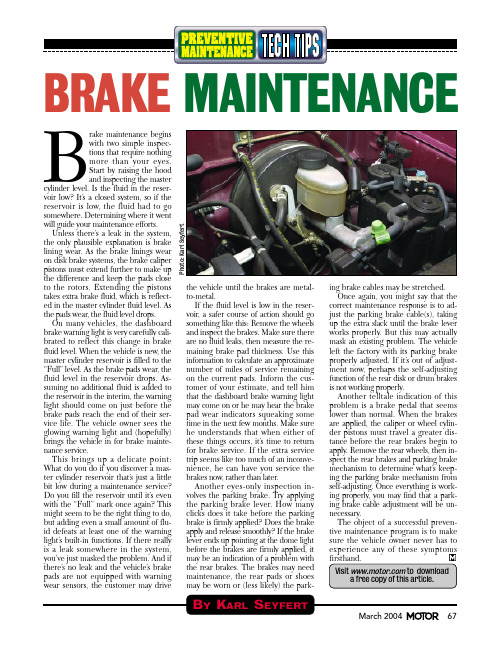
B rake maintenance begins with two simple inspec-tions that require nothing more than your eyes.Start by raising the hood and inspecting the master cylinder level. Is the fluid in the reser-voir low? It’s a closed system, so if the reservoir is low, the fluid had to go somewhere. Determining where it went will guide your maintenance efforts.Unless there’s a leak in the system,the only plausible explanation is brake lining wear. As the brake linings wear on disk brake systems, the brake caliperpistons must extend further to make up the difference and keep the pads close to the rotors. Extending the pistons takes extra brake fluid, which is reflect-ed in the master cylinder fluid level. As the pads wear, the fluid level drops.On many vehicles, the dashboard brake warning light is very carefully cali-brated to reflect this change in brake fluid level. When the vehicle is new, the master cylinder reservoir is filled to the “Full” level. As the brake pads wear, the fluid level in the reservoir drops. As-suming no additional fluid is added to the reservoir in the interim, the warning light should come on just before the brake pads reach the end of their ser-vice life. The vehicle owner sees the glowing warning light and (hopefully)brings the vehicle in for brake mainte-nance service.This brings up a delicate point:What do you do if you discover a mas-ter cylinder reservoir that’s just a little bit low during a maintenance service?Do you fill the reservoir until it’s even with the “Full” mark once again? This might seem to be the right thing to do,but adding even a small amount of flu-id defeats at least one of the warning light’s built-in functions. If there really is a leak somewhere in the system,you’ve just masked the problem. And if there’s no leak and the vehicle’s brake pads are not equipped with warning wear sensors, the customer may drive the vehicle until the brakes are metal-to-metal.If the fluid level is low in the reser-voir, a safer course of action should go something like this: Remove the wheels and inspect the brakes. Make sure there are no fluid leaks, then measure the re-maining brake pad thickness. Use this information to calculate an approximate number of miles of service remaining on the current pads. Inform the cus-tomer of your estimate, and tell him that the dashboard brake warning light may come on or he may hear the brake pad wear indicators squeaking some time in the next few months. Make sure he understands that when either of these things occurs, it’s time to return for brake service. If the extra service trip seems like too much of an inconve-nience, he can have you service the brakes now, rather than later.Another eyes-only inspection in-volves the parking brake. Try applying the parking brake lever. How many clicks does it take before the parking brake is firmly applied? Does the brake apply and release smoothly? If the brake lever ends up pointing at the dome light before the brakes are firmly applied, it may be an indication of a problem with the rear brakes. The brakes may need mai ntenance, the rear pads or shoes may be worn or (less likely) the park-ing brake cables may be stretched.Once again, you might say that the correct maintenance response is to ad-just the parking brake cable(s), taking up the extra slack until the brake lever works properly. But this may actually mask an existing problem. The vehicle left the factory with its parking brake properly adjusted. If it’s out of adjust-ment now, perhaps the self-adjusting function of the rear disk or drum brakes is not working properly.Another telltale indication of this problem is a brake pedal that seems lower than normal. When the brakes are applied, the caliper or wheel cylin-der pistons must travel a greater dis-tance before the rear brakes begin to apply. Remove the rear wheels, then in-spect the rear brakes and parking brake mechanism to determine what’s keep-ing the parking brake mechanism from self-adjusting. Once everything is work-ing properly, you may find that a park-ing brake cable adjustment will be un-necessary.The object of a successful preven-tive maintenance program is to make sure the vehi cle owner never has to experi ence any of these symptoms BRAKE MAINTENANCEP h o t o : K a r l S e y f e r t。
堵姆汽车维修指南说明书
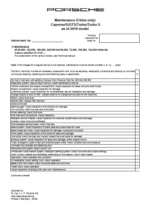
Vehicle Ident. No. _______________________Working instruction fororder no. Maintenance(Labour operation 03 16 00 ..)For a description of the various models, see Technical ManualContinued overleaf PDCC: check fluid levelCayenne/S/GTS/Turbo/Turbo Sas of 2010 model9 At 60,000, 120,000, 180,000, 240,000 km/36,000, 72,000, 108,000, 144,000 miles etc.Diagnostic system: read out fault memory; reset maintenance intervalVehicle underbody and engine compartment: visual inspection for leaks (oils and other fluids)Engine compartment: visual inspection for damageUnderbody panels: visual inspection for completeness, secure installation and damageChange engine oil and oil filter (please observe oil change service plan for the Cayenne)The term 'checking' includes all necessary subsequent work, such as adjusting, readjusting, correcting and topping up, but does not include repairing, replacing and reconditioning parts or assemblies.Mix fuel in fuel tank with additive (Keropur from Porsche; Part No. 000 043 206 89)Note: If the mileage for a regular service is not reached, maintenance must be carried out after 4, 8, 12...... years.Axle joints: check the play and visually inspect the dust boots for damageTyres, emergency spare wheel and external spare wheel: check condition and tyre pressureSteering gear: visual inspection of the bellows for damage.Tie rod joints: check the play and dust bootsFoot-operated parking brake: check free playBrake hoses and lines: visual inspection for damage, routing and corrosionFuel lines and connections: visual inspectionParticle filter: replace filter elementDrive shafts: visual inspection of the boots for leaks and damageRadiators and air intakes: visual inspection for external contamination and blockageCoolant: check level and antifreezeSeat belts: check operation and conditionCopyright byDr. Ing. h. c. F. Porsche AGAfter Sales EngineeringPrinted in Germany - 03/09Lubricate door arrester and fastening pinsAll headlights: check setting; horn: check operationPanorama roof system: teach control unitVisual inspection of airbag units (see Add. Maintenance)Check drive beltBattery and vent hoses: check functional state and fluid levelTrailer hitch: check operationBrake system: visual inspection of brake pads and brake discs for wearPower steering: check fluid levelExhaust system: visual inspection for leaks and damage, check engine mountWindscreen wiper/washer system, headlight cleaning system: check fluid level and nozzle settings;check window cleaner and antifreeze, depending on the season; check wiper bladesVehicle Ident. No. _______________________Working instruction fororder no.every 60,000 km/36,000 miles or every 4 years every 30,000 km/18,000 miles or every 4 years every 20,000 km/12,000 miles or every 4 years (Labour operation 03 83 00 ..)Air cleaner: replace filter element (Cayenne Diesel only)(Labour operation 03 85 00 ..) (Labour operation 03 95 00 ..) (Labour operation 03 51 00 ..) (Labour operation 03 52 00 ..) (Labour operation 03 54 00 ..)Signature (mechanic): _______________________________Test drive:Signature (final check): _________________________Porsche Centre Oils, fluids: visual inspection for leaksCayenne/S/GTS/Turbo/Turbo SAdditional maintenance every 240,000 km/144,000 miles or every 16 years (Labour operation 03 81 00 ..)File condition report for long-life guaranteeRemote control, front seats, foot and parking brakes (also actuation travel), engine, clutch, steering, transmission, ParkAssist, cruise control, PSM switch, heating, air conditioning and instruments: check operationEvery 2 yearsCopyright byDr. Ing. h. c. F. Porsche AGAfter Sales EngineeringPrinted in Germany - 03/09 Additional maintenance, replacing spark plugs Additional maintenance every 90,000 km/54,000 miles or every 6 yearsas of 2010 modelReplace tyre sealing compoundAir cleaner: replace filter element (not for the Cayenne Diesel)Rear final drive: change oilChange brake fluid (use only original Porsche brake fluid)Visual inspection of airbag units (see Maintenance)Additional maintenance every 120,000 km/72,000 miles or every 6 yearsReplace PDCC reservoirEvery 4 yearsAll-wheel final drive: change oilAfter 4, 8, 10 then every 2 yearsReplace spark plugs - Cayenne Turbo/S Replace spark plugs - Cayenne S/GTSReplace spark plugs - CayenneManual transmission: change oilTiptronic transmission: change ATF and ATF filterTransfer gear: change oil。
Svendborg Brakes 2-Stage Hydraulic Power Unit说明书
Hydraulic Power Unit2-StageBrakingP-7902-SV 1/181 |2 WHERE TO USEThe 2-stage hydraulic power unit provide a 2-stage controlled braking sequence for use with hydraulic fail-safe spring applied discbrakes. The 2-stage braking sequence is used to prevent a hard braking sequence, which in worst case can cause too high stress on the mechanical parts, or unwanted wear of the system through uncontrolled braking.BRAKING PERFORMANCEDuring opening of the brakes the pressure is build up and thereby opening the brake(s). The first stage of the braking sequence is dumping the pressure to the correct pressure and after the 2-stage braking time the pressure is smoothly reduced and thereby increasing the braking torque.FUNCTIONAL DESCRIPTIONOperation (Not Braking)Electrical power is connected to the electrical motor and the solenoid valve(s) is/are energized. The braking valve(s) is/are closed and block the connection to tank. The hydraulic pressure is built up and disengages the brake and charges the accumulator.The electrical power is disconnected from the motor by means of the motor pressure switch. The braking valve(s) is/are constantlyenergized. If the pressure is decreasing to the lower set point for motor pressure switch the motor will restart and increase the pressure again.Applying the Brake with Controlled Braking TorqueThe electrical power is disconnected to the braking valve(s) and motor. The hydraulic oil pressure is released to the tank through the counter pressure valve(s) and the throttle valve(s), resulting in a constant reduced braking torque (MT%).The reduced braking time is set by the flow control valve by bleeding the oil from the accumulator slowly through the flow control valve, maintaining a constant pressure in the brakes. When the accumulator is fully discharged the pressure in the brake will go to zero, and full braking torque is applied.The constant brake torque and braking time is pre-set from factory as specified or if not specified set to 50% (MT%) of maximum torque and approximately 10sec stopping time (Δt).Operation in Case of Power FailureIn case of power failure the brakes will be applied as described in the section: Applying the brake with controlled braking torque.Hydraulic force > Spring forcePad is lifted away from disc Hydraulic force = Spring force Pad touches the disc without brakingHydraulic force = 0 Spring force has full force/effect “Quick start”Brakes fully retracted. This can be detected by mechanical/inductiveFEATURESThe hydraulic power unit is available in two versions; a basic (single dump) and a premium (dual dump) with cabinet / enclosure with various options and accessories.The junction box / terminal box is mounted internally in the upper left hand side. Cable entry is in left hand side with removable entry plate in brass. The cabinet door is hinged either left hand or right hand side. The pressure connection / bulkhead (JIC as standard / Ermeto fitting 10L as optional) is mounted in left hand side but can be mounted in the right hand side or in the bottom as well.2-Stage Braking Special Features• Single return line / dump (Basic) or Dual returnlines / dump for redundancy (Premium)• Counter pressure valve(s) and throttle valve(s)• Equipped with hand pump for manual release of brake• Inline high pressure filter• LED’s on solenoids• Test point for readout / bleeding of manifold• Pressure switch either electronic or mechanical type• Level & temperature switch in tank• Pressure gauge mounted on test point (minimess) hose inside cabinet• Stainless steel enclosure mounted on bracket with vibration dampers• Enclosure door with cam lock with double bit as standard or upgraded with stainless pad-lockable swing handle (optional)• Removable drip tray to capture spills• HPU can be mounted on slides for easy maintenance (optional)•Sun roof / dirt cover 30° (optional)Svendborg BrakesP-7902-SV 1/182P-7902-SV 1/183 2relief valveAccumulator Filling cap &Level &(optional)relief valveAccumulator Fillling cap &Level &(optional)Pressure gauge (optional)Test point nipple Adjustable throttle valveCheck valveIn-line filter (10 micron)Electric motorGear pump Level glassSafety relief valve Counter pressure valve Braking valveHYDRAULIC DIAGRAMThe schematics illustrates the difference between basic (single return) & premium (double return). The additional circuit on the premium version is marked with red in the below image.The motor pressure switch can either be mechanical type (2 switches) or electronic type (IFM) (1 switch) – here shown as electronic type.Basic Version: Single Dump / Single Return LinePremium Version: Double Dump / Dual Return LineRed area indicates additional circuit for redundant return/dumpSvendborg Brakes P-7902-SV 1/184Premium Version (Redundant Valves) with IFM Pressure Switch:Premium Version (Redundant Valves) with Mechanical Pressure Switch:ELECTRICAL DIAGRAM / SCHEMATICThe electrical components on the hydraulic power unit – excluding the motor - are prewired to the junction box.The motor supply wire and motor starter is not part of the unit and must be provided locally.The connection from installation to junction box and motor is to be made through the removable brass entry plate in the left hand side and must be made during installation. It is not normal to connect the brake indicators though the junction box on the unit.The electrical diagram / schematic vary according to the selections made (basic / premium / mechanical or electronic pressure switch) –below two typical schematicsP-7902-SV 1/185 2 Component List (Quantities depend on configuration)Valves / Coil Directional poppet valve 2/2 & coil 21W (1x or 2x) - Hydac Pressure switchElectronic sensor (1x) – IFM 7001Mechanical pressure switch (2x) - Bosch Rexroth HED5Level & temperature switch Level indicator with temperature switch 70°C - Lund & Sorensen MotorIEC common motor0,75kW for 50Hz / 0,90kW for 60Hz Terminals (in JB)Screw terminals - WagoWire colorsIEC Power circuit wiring colors Protective earth (PE) Green-yellow Neutral (N) Blue Line, single phase (L) Brown Line, 3 phase (L1) Brown Line, 3 phase (L2) Black Line, 3 phase (L3) GreyRecommended Brake Limits for 2 Stage PressuresChoosing brake torques and brake sizes that result in a hydraulic two stage pressure lower than 10bar (lower limit) is not recommended asthe counter pressure valve is very difficult to set at this low pressure.The brake pressure curves indicate the two stage pressure at the corresponding torque. If pressure is below the ‘lower limit’ the combination is not recommended.BSFI 200 Series:BSFI 3000 Series:BSFI 300 Series:Svendborg Brakes P-7902-SV 1/186Technical SpecificationsMotor standardIEC – TEFC (fan cooled)IEC – TENV (non ventilated)Available motor voltages AC 50Hz / 60 Hz 1 x 230V3 x 400V / 480V 3 x 500V / 575V 3 x 690V / 690VAll AC motors have voltage tolerance ± 10%Power consumption:0.75kW (50Hz)0.90KW (60Hz)Available Coil Voltages DC: 12V , 24V , 48V , 110V AC: 110V , 230VPower consumption: 19W (one coil)Oil Tank Size6 liter / 1.58 gallon (US) /1.32 gallon (imperial)Hand Pump InclusivePressure SwitchElectronic or Mechanical Cabinet / Enclosure Stainless steel (1.4305 /AISI 304) incl. junction box Protection class IP66Protection class for electrical components IP55Internal wiring according to IEC EN 60204-1Mounted on suspension bracket with dampers and lifting point.Drip tray to take spills.Slides for easy maintenance (optional).Ambient Temperature Limits -20°C to +50°C /-4°F to +122°FThe hydraulic fluid must match temperature level AltitudeBelow 1000 MASL WeightApprox.: 100kg / 220lb (without oil)SELECTION SHEET – 2 STAGE HYDRAULIC POWER UNITDimensions (600x800x400mm) (WxHxD)Junction BoxDrip TrayHPU Selection SheetVersion (select one)Premium (dual return)Basic (single return)Accesories (select one)Unit mounted on slides (default)Unit fixed on bracketMotor (AC 50 Hz/60Hz)TEFC =Fan cooled TENC = Non Ventilated(Select one)TENV TEFCDoor mounting (select one)Left side mounted (default)1x230V 50 Hz / 1x230V 60 Hz Right side mounted 3x400V 50 Hz / 3x480V 60 Hz 3x500V 50 Hz / 3x575V 60 Hz 3x690V 50 Hz / 6x690V 60 HzCabinet accesoriesCam lock with double bit (default)Pad-Lockable swing handleCoil voltage (select one)AC DCFlat cabinet (no sun roof)(default)12 VDC 24 VDC48 VAC / VDC 110 VAC 230 VACDust cover / sun roof 30°Pressure connection entry (select one)Left side mounted (default)Right side mounted Bottom (left) mountedPressure switch (select one)Electrical (IFM) (Port P1)Mechanical (Port 40 & 42)Pressure connection type (select one)JIC connection (default)Ermeto connection (10L)Hydraulic / brake parameters:Brake series / size:Type of brake (Mono / Dual)Number of brakes:Braking torque M T % (30-70%):(% of 100% torque)Braking time Δt (5-25sec): (2-stage time)Standard (if no values given): M T % =50% & Δt =10 sec Customer Name / Project:Other Information:Name & Date:pcs %Sec–––––––T he Brands of Altra Industrial MotionC ou plingsAmeridrivesBibby Turbo exwww.bibbyturbo Guardian Couplings HucoLami ex Couplings mi StromagTB Wood’sGeared Cam Limit Switches Stromag Electric Clutches & BrakesInertia DynamicsMatrixStromagWarner ElectricLinear ProductsWarner LinearEngineered Bearing AssembliesKilianHeavy Duty Clutches & BrakesIndustrial ClutchTwi exwww.twi StromagSvendborg BrakesWichita ClutchBelted DrivesTB Wood’sGearingBauer Gear MotorBoston GearDelroyd Worm GearNuttall GearOverrunning ClutchesFormsprag ClutchMarland ClutchStieber ClutchSvendborg Brakes FacilitiesEuropeJernbanevej 9DK-5882 Vejstrup - Denmark +45 63 255 255*********************** Industrial Brakes andBrake Systems Global RepresentationsAustraliaSvendborg Brakes Australia Pty., Ltd.Perth+61 (0) 8 94 160300Svendborg Brakes Australia Pty., Ltd.Newcastle+61 (0) 8 94 160300Svendborg Brakes Australia Pty., Ltd.Brisbane+61 (0) 8 94 160300BrazilAltra Industrial Motion Brazil+55 11 4615-6300 /+55 11 5679-6553ChileSvendborg Brakes ChileCoquimbo+56 23 203 9150Svendborg Brakes ChileSantiago+56 23 203 9150ChinaSvendborg Brakes Shanghai Co., Ltd.+86 21 50311060Czech RepublicSvendborg Brakes Czech Republic+420 (251) 6801 68DenmarkSvendborg Brakes ApS+45 63 255 255GermanySvendborg Brakes ApS+49 5422 9272 00IndiaSvendborg Brakes India***********************KoreaSvendborg Brakes, Korea Co., Ltd.+82 10 9703 0979PolandSvendborg Brakes Poland+48 (322) 1150 40South AfricaAltra Industrial Motion South Africa+27 (0) 11 918-4270SpainSvendborg Brakes+34 (975) 2336 55USASvendborg Brakes, USA LLC+1 (303) 285 1271Neither the accuracy nor completeness of the information contained in this publication is guaranteed by the company and may be subject to change in its sole discretion. The operating and performance characteristics of these products may vary depending on the application, installation, operating conditions and environmental factors. The company’s terms and conditions of sale can be viewed at /terms-and-conditions/sales-terms-and-conditions. These terms and conditions apply to any person who may buy, acquire or use a product referred to herein, including any person who buys from a licensed distributor of these branded products.©2017 by Svendborg Brakes LLC. All rights reserved. All trademarks in this publication are the sole and exclusive property of Svendborg Brakes LLC or one of its af liated companies. P-7902-SV 1/18。
蓝光 主机制动器维保手册讲解
维保手册 GETM15C 主机制动器 Dwg : 蓝光主机_FSM_ZH Date : 25/04/2012 Page: 6/8 FSM Nb # 常规检查抱闸制动力的调整常规检查 2.1 抱闸制动力的调整出厂的曳引机抱闸制动力矩根据载荷已基本调整好,一般情况下现场不需重新调整。
制动系统的制动力矩按曳引机额定转矩的 2.2 倍整定,制动力矩的大小与弹簧的压缩量成正比。
2.2 制动系统调整方法首先,应确认永磁同步曳引机制动系统的工作状态,选择最佳的调整方法。
注意!!!在调整曳引机制动系统前应确认电梯工况位置,防止在调整过程中发生冲顶、墩底等溜车失控,确认控制 ( 自动系统有否存在“封星”制动装置。
警告!曳引机在悬挂负载后,双侧制动臂的调整不能同时进行。
敬告 ! 1 、曳引机制动系统调整时,应确保单侧制动臂有足够的制动力,然后调整另一侧; 2 、永磁同步曳引机的制动系统与传统的异步有齿曳引机有区别,闸瓦与制动轮在开闸时,上下间隙可以不同。
永磁同步曳引机制动系统结构示意图 1—调整螺母 2—紧锁螺母 3—锁紧螺母 4—顶杆螺钉 5—压缩弹簧 6 —弹簧垫圈 7 —压缩螺母 8—锁紧螺母 9—顶紧螺钉 10—锁紧螺母 11—制动瓦12—拉杆锁紧螺母 13—拉杆 14—顶杆螺钉 15—制动器顶端压缩弹簧 16—手动开闸手轮 17—标尺维保手册 GETM15C 主机制动器 Dwg : 蓝光主机_FSM_ZH Date : 25/04/2012 Page: 7/8 FSM Nb # 常规检查主要零部件功能 2.3 主要零部件功能: 1 —调整螺母,调整其位置可控制制动体内部衔铁始终处于合适的位置,保持合理的工作行程,避免合闸时冲击衔铁,撞击手动开闸凸轮,发出噪声; 4 —控制开闸力的形成,在“ 13 ”最大开闸间隙形成的条件下,控制制动臂的行程及制动闸瓦与制动轮的工作间隙; 5 —压缩弹簧,调整其压缩量可控制制动力的大小,压缩量过大会导致制动体开闸困难; 7 —压缩螺母,调整位置,可控制制动力的大小; 9 —顶紧螺钉,控制闸瓦与制动轮的吻合程度, ( 制动闸瓦与制动轮吻合越好,在相对条件下,形成的制动力就越大,工作噪声越小; 13 —拉杆,决定制动力的形成,控制最大开闸间隙; 2 、 3 、 8 、 10 —锁紧螺母,防止在调整完成后,系统动作后各调整螺钉松动,致使系统改变; 17 —标尺,只是系统在恢复原制动力的参考标记。
SEW-EURODRIVE维护系列刹车调整说明书
Verify the free play on the release arm. adjust the locking nuts as needed to achieve
1.5 – 2.0 mm gap. (S Dimension)
Caution!
There must always be clearance on the lever.
SEW Maintenance Series
Brake Adjustment
SEW-EURODRIVE—Driving the world
Product Training
Brake Adjustment
2
Objectives
After studying the contained information you will be able to accomplish the following:
Product Training
Brake Adjustment
17
Step 12
To determine the correct free play (clearance), please refer to the next to last paragraph on page 4 of the Motor and Brakemotor Operating Instructions (Document # 09 793 77).
Using the flat tip screwdriver, re-install the rubber brake band, using caution to not damage the band.
SEW-EURODRIVE—Driving the world
03.制动装置使用维护说明书

车辆制动装置使用维护说明唐山轨道客车有限责任公司车辆制动装置使用维护说明1.概述车辆制动装置由空气制动装置、基础制动装置和手制动装置组成。
其中空气制动装置是产生制动的原动力的部分,基础制动装置是传递和放大制动力的部分,手制动装置是以人力为动力来源,用手来操纵的制动装置。
2.基本作用原理自动空气制动机的作用原理是“减压制动,增压缓解”。
这里的减压或增压指的是列车管增压或减压。
正常运行状态列车管充以定压空气(600KPa),当司机操纵列车制动阀,将列车管的压力空气排入大气时,车辆制动装置中的分配阀将处于制动位,副风缸的压力空气充入制动缸,产生制动作用。
反之,司机操纵列车制动阀,将机车总风缸的压力空气充入列车管,当列车管充到定压时,分配阀将处于缓解位,制动缸内压力空气就会排入大气,车辆制动装置处于缓解状态。
3. 空气制动装置(见附图1所示)车辆空气制动装置由总风管、列车管、104分配阀、副风缸、工作风缸、制动软管连接器、截断排风塞门、球芯折角塞门、球芯截断塞门、组合式集尘器、紧急制动阀、金属软管及管路等组成。
车辆施行段修时,对空气制动装置,除风缸及制动管在一般情况下不分解外,其余的空气制动配件,均须施行分解检修,而其中分配阀、缓解阀、折角塞门、制动软管、紧急制动阀、风表等均须卸下送制动室集中检修。
3.1 空气制动装置统中各组成部件的作用3.1.1 104型客车空气分配阀根据列车管内空气压力变化,使制动装置产生充气缓解、常用制动、制动中立和非常制动四个作用。
3.1.2列车管它是贯通全车的空气导管。
它把机车提供的压缩空气输送给车辆制动装置的各储风缸。
司机通过改变其管内的压缩空气的压力来操纵制动机的制动、缓解和保压作用。
制动主管的名义通径为Dg25。
3.1.3支管支管是指分配阀联系列车管、制动缸、副风缸及工作风缸的支管路。
除了分配阀到列车管之间的管路通径为Dg25外,其余支管的通径为Dg20。
3.1.4管路接头管路接头将管子连接为一体。
潍杰自动汽车维修指南说明书

IndexAccessoriesInstallation................................. 115ACCESSORY (Ignition KeyPosition)....................................... 50AddingAutomatic TransmissionFluid........................................ 154Brake Fluid................................ 156Clutch Fluid.............................. 158Differential Oil.......................... 155Engine Coolant......................... 149Engine Oil.................................. 145Manual Transmission Fluid... 155Power Steering Fluid.............. 158Windshield Washer fluid......... 153Additional Safety Information.... 17Door Locks.................................. 18Driving with Pets....................... 18Head Restraint Position............ 17Seat-back Position..................... 17Storing Cargo Safely................. 18Additives, Engine Oil.................. 146AdjustmentsHead Restraints (57)Mirrors......................................... 63Seats.............................................. 54Steering Wheel........................... 44Airbag (SRS).................................... 11Air Cleaner.................................... 159Air Conditioning............................. 76Maintenance.............................. 167Usage............................................ 76Air Outlets (Vents)......................... 72Air Pressure, Tires...................... 168Alarm, Anti-theft......................... 106Alcohol and Drugs.......................... 27Alcohol in Gasoline...................... 108Aluminum Wheels, Cleaning..... 187Antifreeze...................................... 149Anti-lock Brakes (ABS)Description................................ 218Indicator Light.................. 35, 128Operation................................... 128Anti-theft Steering ColumnLock .............................................50Anti-theft System........................ 106Appearance Care.......................... 185Ashtrays. (68)Audio System..........................79, 189Automatic Speed Control (46)Automatic Transmission............ 122Capacity, Fluid.......................... 216Checking Fluid Level.............. 154Shifting....................................... 122Shift Lever Positions............... 123Shift Lock Release. (126)Back-up Lamp Replacement (180)BatteryCharging System Light............. 34Jump Starting........................... 201Maintenance.............................. 162Specifications............................ 217Before Driving.............................. 107Belts, Seat.......................................... 5Body Repair.. (192)CONTINUEDIndexBrakesAnti-lock System (ABS).......... 128Break-in, New Linings............ 108Fluid............................................ 156Light, Burned-out.................... 180Parking......................................... 65System Light............................... 34Wear Indicators........................ 127Brakes, ABSDescription................................ 218Operation................................... 128System Indicator............... 35, 128Braking System............................ 127Break-in, New Car....................... 108Brightness Control,Instruments................................. 41Brights, Headlights........................ 40Bulb ReplacementBack-up Lights......................... 180Brake Lights............................. 180Courtesy Lights........................ 182Fog Lights................................. 176Front Parking Lights.............. 179Front Side Marker Lights...... 179Headlights................................. 174High-mount Brake Light.. (181)Interior Lights.......................... 182License Plate Lights................ 181Rear Side Marker Lights........ 180Specifications............................ 217Turn Signal Lights .................. 178Bulbs, Halogen (174)Cables, Jump Starting With....... 202Cancel Button................................. 48Capacities Chart........................... 216Carbon Monoxide Hazard ............ 28Cargo, Loading.............................. 116Cassette PlayerCare............................................. 104Operation.............................. 86, 96CAUTION, Explanation of............ ii CD Player....................................... 101Certification Label....................... 214Chains............................................. 173Change OilHow to........................................ 147When to...................................... 139Changing a Flat Tire................... 195Changing Engine Coolant.. (150)Charging System Light...... 34, 206Check Engine Light............ 35, 207CheckingAutomatic TransmissionFluid........................................ 154Battery Condition..................... 162Brake Fluid................................ 156Clutch Fluid.............................. 158Differential Oil.......................... 155Engine Belts.............................. 168Engine Coolant......................... 149Engine Oil.................................. 145Fuses.......................................... 209Manual Transmission Fluid... 155Power Steering Fluid .............. 158Checklist, Before Driving........... 118Childproof Door Locks.................. 52Child Safety..................................... 19Cigarette Lighter........................... 67Cleaner, Air................................... 159CleaningAluminum Wheels................... 187Exterior...................................... 186Interior....................................... 189Leather....................................... 189Seat Belts...................................190IndexVinyl........................................... 189Windows..................................... 190Wood Trim................................ 189CLEAN Light............................... 104Clock, Setting the........................... 66Clutch Fluid................................... 158Code, Audio System..................... 105CO in the Exhaust........................ 220Cold Weather, Starting in........... 120Compact Spare.............................. 194Console Compartment................... 67Consumer Information................ 225Controls, Instruments and............ 31CoolantAdding........................................ 149Checking.................................... 149Proper Solution......................... 149Temperature Gauge.................. 38Corrosion Protection.................... 191Courtesy Lights.............................. 70Crankcase Emission ControlSystem........................................ 220Cruise Control Operation.............. 46Customer Relations Office (225)DANGER, Explanation of.............. ii Dashboard........................................ 39Daytime Running Lights.............. 40Dead Battery, What to Do.......... 201Defects, Reporting Safety............ 29Defogger, Rear Window............... 44Defrosting the Windows............... 78DEXRON ® II AutomaticTransmission Fluid.................. 154Differential Oil.............................. 155Digital Signal Processor................ 99Dimensions.................................... 216Dimming the Headlights .............. 40DipstickAutomatic Transmission........ 154Engine Oil.................................. 145Directional Signals......................... 41Disabled, Towing Your Car If ... 212Disc Brake Wear Indicators....... 127Disposal of Used Oil..................... 148DoorsLocking and Unlocking............. 51Monitor Light............................. 35Power Door Locks. (51)DOT Tire Quality Grading......... 171Downshifting, 5-speed ManualTransmission............................. 121Driving............................................ 117Economy..................................... 114In Bad Weather......................... 129In Foreign Countries (109)Economy, Fuel.............................. 114Emergencies on the Road........... 193Battery, Jump Starting ........... 201Changing a Flat Tire............... 195Charging System Light.......... 206Check Engine Light................ 207Checking the Fuses................. 209Low Oil Pressure Light.......... 205Malfunction IndicatorLamp....................................... 207Manually Closing Moonroof.. 208Overheated Engine.................. 203Emergency Brake.......................... 65Emergency Flashers. (43)CONTINUEDIndexEmission Controls........................ 220EngineCheck Light....................... 35, 207Coolant Temperature Gauge... 38Malfunction IndicatorLamp............................... 35, 207Oil Pressure Light.............34, 205Oil, What Kind to Use ............. 146Overheating............................... 203Specifications............................ 216Ethanol in Gasoline...................... 109Evaporative EmissionControls...................................... 220Exhaust Fumes............................... 28Exhaust Gas RecirculationSystem........................................ 221Expectant Mothers, Use ofSeat Belts by................................ 10Exterior, Cleaning the.. (186)Fabric, Cleaning........................... 189Fan, Interior.................................... 73Fan, Radiator. (30)Features, Comfort andConvenience................................ 71Filling the Fuel Tank .................. 110FiltersFuel............................................. 160Oil................................................ 147First Gear, Shifting...................... 1225-speed Manual TransmissionChecking Fluid Level.............. 155Shifting the................................ 121Flashers, Hazard Warning ........... 43Flat Tire, Changing a.................. 195FluidsAutomatic Transmission........ 154Brake.......................................... 156Clutch......................................... 158Differential ............................... 155Manual Transmission.............. 155Power Steering......................... 158Windshield Washer.................. 153FM Stereo RadioReception...............................81, 91Foreign Countries, Driving in.... 109Four-way Flashers......................... 43Front End, Towing byEmergency Wrecker (212)Fuel................................................. 108Fill Door and Cap...................... 110Filter........................................... 160Gauge............................................ 38Octane Requirement............... 108Oxygenated............................... 108Reserve Indicator....................... 36Tank, Filling the....................... 110Fuel Mileage, Improving ............ 114Fuel Station Procedures ............. 110Fuses, Checking the .. (209)Gasohol........................................... 108Gasoline.......................................... 108Filter........................................... 160Fuel Reserve Indicator............. 36Gauge............................................ 38Octane Requirement............... 108Tank, Filling the....................... 110GaugesEngine Coolant Temperature.. 38Fuel............................................... 38GAWR (Gross Axle WeightRating)........................................131IndexGearshift Lever PositionsAutomatic Transmission........ 1235-speed ManualTransmission......................... 122Glass Cleaning.............................. 190Glove Box......................................... 53GVWR (Gross Vehicle WeightRating) (131)Halogen Headlight Bulbs............ 174Hazard Warning Flashers............ 43HeadlightsDaytime Running Lights.......... 40High Beam Indicator................. 36High Beams, Turning on.......... 40Low Beams, Turning on........... 40Reminder Chime........................ 40Replacing Halogen Bulbs....... 174Turning on................................... 40Heating and Cooling...................... 72High Altitude, Starting at.......... 120High-Low Beam Switch ............... 40Hood, Opening the........................ 111Horn.. (49)Hot Coolant, Warning about...... 149Hydraulic Clutch.......................... 158Hydroplaning.. (130)Identification Number,Vehicle........................................ 214If Your Car Has to be Towed..... 212IgnitionKeys.............................................. 49Switch........................................... 50Timing Control System........... 221Indicator Lights, InstrumentPanel............................................. 33Infant Restraint.............................. 19Inflation, Proper Tire.................. 168Inside Mirror................................... 63Inspection, Tire............................. 169Instrument Panel............................ 32Instrument Panel Brightness....... 41Interior Cleaning.......................... 189Interior Lights................................ 69Introduction. (i)Jacking up the Car....................... 197Jack, Tire....................................... 196Jump Starting.. (201)Keys (49)Label, Certification...................... 214Lane Change, Signaling................ 41Lap/Shoulder Belts.......................... 6Lap Belt.............................................. 6Leaking of Exhaust into Car........ 28Leather, Cleaning......................... 189Lighter, Cigarette.. (67)CONTINUED。
博美德伺服驱动器说明书
第 2 章 安装与接线...................................................................................................................... 10
SEW制动器安装培训教材3

4.根据需要的制动力矩均匀摆放弹簧
Driving the world
Training \ Service \ Service Regulation
15
5.放上阻尼盘(仅限于BMG)
Driving the world
Training \ Service \ Service Regulation
6
制动器线圈正常状态
异步电机所用制动器线圈 有三个出线头,分别为白 色,红色,蓝色,用万用 表测量,白色线与红色线 间的阻值、白色线与蓝色 线间的阻值与SEW公司提 供的相关阻值相等
Driving the world
Training \ Service \ Service Regulation
7
附图(正确接线图)
Training \ Service \ Service Regulation
24
制动器安装
Driving the world
Training \ Service \ Service Regulation
25
制动齿轮与制动器完全啮合后用锤子敲打紧固
Driving the world
Training \ Service \ Service Regulation
Driving the world
Training \ Service \ Service Regulation
32
风扇叶的装配
Driving the world
Training \ Service \ Service Regulation
33
风扇罩的组装
Driving the world
Training \ Service \ Service Regulation
斯温博格喷气刹车产品说明书
P-1723-18-SV 5/16Printed in USASvendborg Brakes' comprehensive product range makes us your answer to one-stop brake shopping and supply. Our complete braking solutions include extensive design services, market-leading products, a quality-focused supply chain and unmatched after salesservices.Hydraulic Brakes - FailsafeSpring applied/hydraulic released failsafe disc brakes commonly used for parking or emergency stopping in case of power failure. Brake model and spring pack selection sized to suit specific application and customerrequirements. Brakes are available in either Dualspring or Monospring design and in standard finish or a corrosion resistant finish.Hydraulic Brakes - ActiveActive brakes are hydraulic applied/spring released discbrakes typically used for stopping, tensioning or holding purpose. The hydraulic pressure ensures a constant braking torque throughout the life of the pads. Brakes are available in either Dualspring or Monospring design and in standard finish or a corrosion resistant finish.Hydraulic Brakes - CustomApplication specific brakes such as Mill Brakes, Drawworks Brakes and Elevator Brakes are available to meet different customer and application requirements.Depending on the application, these brakes are offered with steel yokes and different types of certifications including DNV , ABS and API. Brakes are available in a standard finish or a corrosion resistant finish.Hydraulic Power Units -On/Off / 2 Stage Braking / SOBO ® iQOptional controlled braking sequence for use with Svendborg calipers.Controlled braking is used to prevent a hard/abrupt braking sequence. HPU is available with cabinet / enclosure and various options and accessories.Hydraulic Power Units - Application SpecificSpecific application HPU's forConveyors, Mills, Drawworks, Hoists, Cranes, Elevators etc. Each design is engineered and tested in cooperation with our customers, so we make sure all requirements are met.SOBO ® iQ ControllerSOBO ® iQ is a revolutionary soft braking technology for a variety of applications including Conveyors, Cranes, Hoists, Water Gates,Bridges, Barge Unloaders etc. If youneed safe and consistent stopping times independent of load or if you require to stop within a certain distance SOBO ® iQ is the answer.Brake DiscsSvendborg Brakes can supply brake discs according toapplication requirements. Standard sizes as well as custom sizes and special designs such as split discs are available.R&D & Test Center Extensive testing in our full scale test center is second to none and your guarantee for top quality. We have a strong tradition for R&D investments and an invaluable accumulated know-how. Our focus on innovation and testing is core to our company.Service OrganizationSvendborg Brakes field service technicians ensure correct adjustment of brakes, hydraulics and SOBO ®. A preventative maintenance visit minimizes downtime. A detailed service report including recommendations is always provided.Global FootprintOur global organization is always close to our customers. This means we can quickly be on site even in the most remote locations, which minimizes the downtime for our customers.OEM Spares & AccessoriesOEM spare parts are worth far more than compromising on price, quality and safety. We guarantee that all our products meet orexceed local regulations and safety standards.Engineering Support Our engineering team ensures your braking system is sized right for your project. We include our hydraulic, mechanical and electrical engineering team on each project. Trust is what we deliver to our customers. If anyone can do it,we can.Customer Service & Application SupportNorth America: +1 303 285 1271***********************South America: +56 23 203 9150***********************INDUSTRIALGet ConnectedThe Altra Newsroom makes it quick and easy for you to get the news you need when you need it. From new literature releases to trade show schedules, the news is at your fingertips 24 hours a day./newsroomEverything AltraFrom the Altra homepage you can connect to all of our brands, and visit our market portals to find solutions for yourspecific needs.Literature PortalConveniently download and request Altra's latest catalogs, brochures, service manuals and more on the Literature Portal. Find thelatest product information to meet your power transmission requirements by going to any Altra brand website and clicking onthe Literature tab.Like us on Facebook and follow us on Twitter for up to the minute news you can use. Link with us on LinkedIn, follow us on Google+, and find us on YouTube to watch training videos and application movies.Altra Industrial Motion The Power Of ExperienceAmeridrives Couplings Ameridrives Power Transmission Bauer Gear Motor Bibby Turboflex Boston GearDelroyd Worm Gear Formsprag Clutch Guardian Couplings Huco Dynatork Industrial Clutch Inertia DynamicsKilian Manufacturing Lamiflex Couplings Marland Clutch Matrix International Nuttall Gear Stieber ClutchSvendborg Brakes TB Wood’s Twiflex Limited Warner Electric Warner Linear Wichita ClutchOnline Resources。
SEW-制动器的使用维护
8压力盘
18设置螺母
9阻尼盘(仅BMG) 19风扇
10a螺柱(3x) 20卡簧
b反向弹簧
21风扇罩
c压力圈
22螺栓
e六角螺母
2005.01.08
2
制动器的使用维护
制动器的工作原理
SEW制动器为直流厉磁盘式制动器, 制动线圈分为两部分,即加速线圈 与保持线圈,当电流从整流块输出 之后进入制动线圈,加速线圈在极 短的时间内形成很大的电磁力克服 弹簧的势能将压力盘完全回吸(此 时制动器打开)后经极短的时间切 换至保持线圈开始正常的工作。
2005.01.08
8
制动器的使用维护
BR03制动器
4.在制动时测量x距离(见下图) -从压力盘螺柱端(8)到制动器线圈(11)之间的距离
5.通电打开制动器 6.制动器打开时,测量x距离-从压力盘上的螺柱端(8)到制动线圈(11)之间的
距离 7.差值等于工作间隙,也就是压力盘(18)的行程
-如果工作间隙≤0.8mm,重新装上锥型弹簧(17),手动释放架(14)和锁紧螺 母(16)
制动器的使用维护
客户服务中心
2005.01.08
1
制动器的使用维护
制动器的结构
1带有制动轴承后 11制动弹簧
端盖的电机 ★12制动线圈体
2花键
13 In BMG:油封垫
3卡簧
In BM:V圈
4Niro盘(仅BMG) 14销柱
5橡胶密封外圈 15释放手柄
6环行弹簧
16螺柱(2件)
★7制动盘
17锥型弹簧
2005.01.08
14
制动器的使用维护
整流块工作原理
BS:加速线圈 R1:压敏电阻 TS:维持线圈 R2:压敏电阻 D1:整流二极管 IB:加速电流 D2续流二极管 IH:维持电流 T1:可控硅
- 1、下载文档前请自行甄别文档内容的完整性,平台不提供额外的编辑、内容补充、找答案等附加服务。
- 2、"仅部分预览"的文档,不可在线预览部分如存在完整性等问题,可反馈申请退款(可完整预览的文档不适用该条件!)。
- 3、如文档侵犯您的权益,请联系客服反馈,我们会尽快为您处理(人工客服工作时间:9:00-18:30)。
安装维护手册液压故障保险盘式制动器BSFI 3090-MS35S-104 AWA PWE 1570 / 77目录1. 概述 (4)1.1 联系人 (4)1.2 安全 (4)1.3 此手册中的常规惯例 (6)1.4 弃权声明 (7)1.5 换算系数 (7)1.6 铭牌/序号 (8)1.7 制动器是如何工作的。
(10)1.8 功能 (11)1.9 运输 (12)1.10 接口 (13)1.11 润滑 (15)1.12 存放 (16)1.13 处理 (16)1.14 如何采购备件 (17)2. 安装 (17)2.1 吊升和装卸 (17)2.2 清洁制动盘 (17)2.3 清洁安装表面 (18)2.4 装卸/安装制动瓦片 (18)2.5 安装制动器 (21)2.6 检查间隙 (26)2.7 检查制动器的对中调整 (26)2.8 定位系统 (27)2.9 调整定位系统 (29)2.10 制动钳排气和冲洗 (32)2.11 安装指示器 (33)2.12 研磨 (34)2.13 拆下制动器 (35)3. 维护 (37)3.1 指示器 (37)3.2 更换制动瓦片 (37)3.3更换其他部件 (40)3.4 拆下主动制动钳 (41)3.5 更换密封件 (42)3.6 检查弹簧组 (51)3.7 更换弹簧组 (53)3.8 制动器的润滑 (56)4.故障查找 (56)附件A-尺寸图 (60)附件B-装配图,制动器 (61)附件B-装配部件清单,制动器 (62)附件C-备件图,半个制动钳分解图 (64)附件C-备件图,半个制动钳 (65)附件C-备件清单,半个制动钳 (66)附件D-备件图,被动制动钳 (67)附件E-安装图 (68)附件F-定位系统 (69)附件G-“开/关”和“没有调节”指示器 (71)附件H-“瓦片磨损”指示器 (73)附件I-技术参数 (74)附件J-建议使用的流体 (76)附件K-推荐备件 (78)1.概述Svendborg Brakes公司拥有广泛且完整的产品范围,可以为制动器设计者提供了一系列的制动装置,这些装置可以满足关于强大制动的安全性和可靠性以及多用途制动的最高要求。
Svendborg Brakes公司可以为您提供整套的装置,包括:制动器,液压动力站和电子SOBO制动器控制装置。
1.1 联系人如果您对此份手册有任何疑问,请联系当地代表或最近的Svendborg Brakes公司办事处:Svendborg Brakes 公司办事处:丹麦:Jernbanevej 9, DK-5882 VejstrupTel +45 63 255 255e-mail: sb@svendborg-brakes.dk德国:Kirchnerstrasse 42, DE-32257 BündeTel +49 522 368 540-0e-mail: sb@svendborg-brakes.de西班牙:C/ San Benito 24, 1ºB, ES-42001 SoriaTel: +34 975 233 655e-mail: sb@svendborg-brakes.es美国:. P.O. Box 1948, Denver, CO 80201-1948Tel: +1 303 285 1271e-mail: sb@或访问我们的网站:1.2 安全Svendborg Brakes公司的制动装置系列产品设计安装在一个旋转的制动盘上以便只和停车制动器系统,工作制动器系统或者紧急停机制动器系统一同使用。
注释:确保在使用非此手册推荐/规定的工具前,您咨询了Svendborg BrakesA/S公司。
●为了保证产品质量和耐用性,请使用来自Svendborg BrakesA/S公司的原装备件。
●保证制动器和液压装置随时保持清洁、无脏物、油脂等是用户的责任。
●保证制动瓦片和制动盘之间的空隙不超过建议值是用户的责任。
●当重新安装螺栓或阀门时,要使用力矩扳手,以便保证获得的力矩是此手册中给出的力矩。
●至少保证维护/服务人员有一本手册。
液压动力站:●在正确安装蓄油罐/油箱和油前,不能操作液压动力站。
●不能将阀门或压力开关的压力调节得高于此手册给出的工作压力。
●不能更换部件的尺寸和型号。
●不能使用非此手册推荐的液压油。
制动器:●在为液压系统放气并且注油前,不能操作制动器。
●不能使用高于制动器铭牌/或此手册中给出的工作压力。
●不能更换弹簧组的尺寸和型号。
●当制动瓦片磨损到手册给出的最小厚度时,不能再继续使用制动瓦片。
●如果在制动盘或制动瓦片上有脏物或锈蚀,则不能操作制动器。
人员安全在下列情况下,不得操作制动器/系统:●在没有阅读和理解此手册前。
●在调整制动器和/或间隙前,制动盘被锁住并且不能转动。
●如果在有弹簧作用的制动器上工作,要通过使用空隙螺栓/空隙螺母来锁住/固定制动器活塞。
●确保在液压动力站或液压线路上没有压力。
●确保蓄能器中的油压已经释放/卸压。
●在操作系统前,控制信号已经关断和闭锁。
●电源已经被断开。
重型设备当吊升制动器或制动器部件时要小心,因为它是重型设备并且不适合手工搬动。
使用正确的吊升设备,以便防止人员伤害。
警告在制动器活塞没有适当固定前,严禁将手指放入制动瓦片和制动盘之间。
压力警告在确定端盖已经旋入轭架足够深之前,严禁给制动器加压。
在加压时如果端盖没有完全把紧,螺纹会被损坏并且端盖螺丝会从制动器中弹出。
避免皮肤长期接触液压油,在使用液压油之前,阅读制造商手册。
如果使用清洁溶剂,必须在使用前阅读制造商手册,然后再按照手册的说明进行操作。
1.3 此手册中的常规惯例为了确保您正确进行操作,请在使用此份手册时注意下列符号。
警告:在试图完成一项任务时,用于防止人员伤害的信息。
警告:在试图完成一项任务时,用于防止损坏部件的信息。
重要:你必须遵守的用于执行任务的信息。
注意:协助完成任务的提示和额外信息。
括号内的数字和位置号有关,附录号,即:(15-C)指的是附录C图纸和材料单(部件清单)中的位置号15。
1.4 弃权声明Svendborg BrakesA/S公司保留在没有事先通知的情况下修订此文件的权利。
已经对此份文件进行了翻译和正确性的校对。
除此以外,有时会出现技术和印刷偏差。
此份文件会定期更新,不同之处会在以后的印刷品中给出。
在没有给出事先通知的情况下,可以随时进行上述产品或手册的改进和/或修改。
在任何情况下,Svendborg BrakesA/S公司对任何特殊的、附带的、间接的或惩罚性损害赔偿都不负责任。
包括但不仅限于:对其他财产或人员造成的损害,不便、信誉损失、利润或收入损失、此种产品或任何相关设备的使用损失、代用设备的费用、停产费用或其他方的索赔,这些损失是由于此份手册中的拼写错误或不正确信息造成的。
在事先没有得到Svendborg BrakesA/S公司的书面许可的情况下,此份文件或文件中的部分在任何情况下都不能被复印、复制、变更或翻译成其他语言。
1.5 换算系数此手册中的所有单位都为公制单位。
如果您需要在公制和英制之间进行换算,可以使用下列图表。
例如:115bar =11.5MPa=1667.94 PSI320N/mm2 =46412.00 PSI305Nm =224.96 lbf.ft1.6 铭牌/序号在联系Svendborg BrakesA/S公司或你方当地销售商之前,请记下产品的序号。
这便于辨别所供的实际产品并且便于帮助确定可能发生的问题。
Brakes-标记/铭牌此标记位于制动器上并且外表特征如下:制动器的命名:“TYPE”型号是制动器的名称。
我公司制动器的命名遵从以下命名方式:BSFI 3000-MSXXX-XXXBS = 制动器系统F =故障保险-弹簧夹紧/液压打开I =制动器版本3000 =夹紧力-最后3个数字单位为kN,即:3090=90,000NMS = 单弹簧XX =制动盘的厚度,单位mmX =完工(S/R)(标准/离岸)-1XX =制动器的版本/选择号例子:BSFI 3090-MS35S-104意思是这是BSF1 3000制动器系统中夹紧力为90,000N 的、制动盘为35mm的标准完工的单弹簧制动器,处于104选项中,相当于AWA 制动器。
序号:序号位于铭牌上,在标签上的标记是SERIAL NO.。
序号是唯一的编号,可以用于辨别制动器的产地、生产日期(年月日)和序列号。
例如:DK 040317/02表示这是02号制动器,产于2004年3月17日,产地为丹麦。
为了便于追踪,还将序号写在发货通知/发票上。
铭牌/标记上的其他信息“ITEM NO”表示制动器的项目号,包括版本号。
“CLAMPING FORCE”和“OPERATING PRESSURE”制动器的性能由所提供的夹紧力给出。
工作压力必须保证能正确使用制动器。
具有弹簧组的制动器弹簧夹紧的故障保险制动器用提供的最小夹紧力(额定值)和最小工作压力(油压)标注以便保证制动器可以被打开。
1.7 制动器是如何工作的。
制动器是将夹紧力变成制动力矩并将其从制动钳传导到制动盘,目的是为了停止制动盘的转动或在其停止时(停车制动器)防止其转动。
BSFI 3000单弹簧制动器是故障保险弹簧夹紧、液压松开的盘式制动器。
此制动器可以被施予不同的夹紧力。
单弹簧制动器只包括一个弹簧组(贝氏弹簧),这些弹簧位于主动制动钳内侧。
用螺栓和垫片将主动制动钳和被动制动钳安装/连接到一起。
(垫片仅在需要时使用)装配/连接好的制动钳浮在位于被动制动钳内侧的底座和轴承的两个轴上。
当进行制动时,主动制动钳(和制动瓦片1)内的活塞将向制动盘方向移动。
然后制动瓦片2和被动制动钳将向制动盘方向打开并且给制动盘两侧一个制动力,原因是因为主动制动钳和被动制动钳装配/连接到一起并且作为一个整体浮在轴上。
请注意:被动制动钳上的制动瓦片2没有移动。
只有主动制动钳上的制动瓦片移动,为此,被动制动钳上的瓦片保持架要比主动制动钳的保持架低。
只允许制动盘和制动器进行有限的动作。
制动器在安装表面的前后方向上的滑动是受限的。
当移动地太靠近安装表面时,制动器会接触底座,这样会阻碍其自由滑动。
如果情况糟糕的话,会对制动器/制动盘/轮毂/连轴器和/或安装表面造成损坏。
当远离安装表面移动时,轴和底座上的力/力矩将会增大,这样会减小使用寿命。
核对安装图和尺寸图以便获得准确的尺寸、公差和允许的移动范围。
为了防止被动制动钳在轴上错误滑动,在连接制动器的压力孔和液压动力站时,有必要使用挠性液压软管做为连接的最后部件/部分。
此手册适用于制动器BSFI 3090-MS35S-104 AWA。
1.8 功能BSFI 3090-MS35S-104 AWA制动器是具有瓦片磨损自动调节,又称作AWA,的制动器。