警铃组使用说明书
警铃管理制度
警铃管理制度
警铃管理制度
1、警铃的使用原则上由矿调度室发出使用指令后,由指定人员发出警报,并启动相关警铃装置。
2、任何单位或个人,不得以任何理由拆除或迁移警铃装置,严禁随意启动或挪作它用。
3、任何单位和个人都有权利和义务维护整个报警系统。
对破坏和滥用警铃装置的行为,有权制止和处罚,并报告矿调度室。
4、由矿调度室负责,每月定期进行一次警报实验,实验结果要存档案备查,对查出的问题要及时通知有关单位进行处理。
5、警铃的安装位置要求在支护完好、巷道畅通、无积尘、无淋水、无杂物的地点,且该地点附近有固定岗位人员工作,并指定人员管理。
6、警铃的设置由机电科负责设计,并随着开采的延伸和回撤,予以及时调整。
7、当某一地点发生透水、火灾或其它严重灾害情况紧急时,现场人员直接启动警报,通知受灾害地点人员撤离,并及时汇报矿调度室和安全科。
8、警报响起后,任何单位和个人都有权立即组织按避灾路线撤离,对行动迟缓或阻碍撤离的人员,要严肃处理直至追究法律责任。
9、对警铃使用管理过程中,有突出表现的单位或个人,将根据情况予以表扬和嘉奖。
报警器使用说明书
一、概述:品牌大眼睛型号HP-99GSM类型防盗报警电话工作电压12(V)无线接收频率315(MHz)报警喇叭声强120(dB)录音留言时长6(S)储存电话号二、详细说明:品牌大眼睛型号HP-99GSM 类型防盗报警电话工作电压12(V)无线接收频率 315(MHz)报警喇叭声强 120(dB)录音留言时长 6(S)储存电话号码 6(个)电话号码位长 11(位)报警项目多功能密码设置功能有系统安装系统简介 本报警器由报警主机和各种无线连接的配件组成。
当有人非法进入设防区域时,主机就会发出警报声,并且拨打主人的电话,主人收到通知后可立即赶回家或通知附近的亲朋好友处理,也可以通过电话监听现场的声音,进行远程操作。
报警器安装把电话线外线插头插入主机的LINE2孔,用报警器附带的电话线将主机的LINE1孔与电话机相连,然后接上电源和警号,此时主机会发出“B”的一声,电源指示灯常亮,表示主机已开始工作。
门磁安装将随机配备的双面胶把磁条贴在门上,门磁发射盒贴在门框上,安装时注意将磁条靠近发射盒上有指示灯一侧,两者对齐,间距越小越好。
红外探测器的安装红外探测器的原理是感应人体发出的红外线信号,它能感应到人体的移动,探测距离通常为5-12米,红外探头应装在离地2.2米左右的位置,对准要探测的区域。
红外只能安装在室内,不要对着太阳光,不要对着窗户及温度容易改变的地方。
红外安装的位置会影响到探测距离及探测的准确性。
GSM卡安装抽出主机背后的SIM卡盖,用手指压住SIM卡座向后推动,翻开卡座盖板,将SIM卡按豁口位置插入盖板,保持SIM卡缺角与板上缺角方向一致,压下盖板向前推动扣住SIM卡即可。
功能设置所有设置都需要在撤防下进行,所有正确的操作均是长响一声,错误的操作都是两声短响调节报警时警笛音量# 0(0~99) #报警时调节警笛音量大小,0到99之间选择,0是无声,99是最大声。
设置普通报警电话号码 # (1~5) ?...? #设置1~5组电话号码,“1~5”为电话号码的序号;此处“?...?”代表电话号码。
消防系统操作说明书

兆科药业(广州)有限公司厂房及厂房A消防系统操作说明书广东华冠消防工程有限公司二O一四年三月(仅供参考使用)目录A.自动喷淋系统 (3)1、自动喷淋系统简介 (3)2、分布情况 (3)3、系统操作说明 (4)4、自动喷淋系统之一般重组系统操作 (5)5、湿式报警阀组之操作说明 (6)6、自动喷淋水泵启动控制屏 (7)7、自动喷淋系统之保养程序 (11)8、自动喷淋系统动作方框图 (12)8、自动喷淋系统系统图 (13)B.室内消火栓系统 (14)1.室内消火栓简介 (14)2.分布情况 (14)3.系统操作说明 (15)4.室内消火栓系统之重组系统操作 (16)5.消火栓水泵起动控制屏 (16)6.室内消火栓系统之保养程序 (19)7.室内消火栓系统动作方框图 (20)8.室内消火栓系统系统图 (21)C.室外消火栓系统 (22)1.室外消火栓系统简介 (22)2.分布情况 (22)3.系统操作说明 (22)4.室外消火栓系统之重组系统操作 (22)5.室外消火栓系统之保养程序 (23)D.火灾自动报警及联动控制系统 (24)1. 火灾自动报警及联动控制系统简介 (24)2.系统分布情况 (24)3.系统操作说明 (25)4.自动报警系统之重组系统操作说明 (26)5.自动报警系统之保养程序 (27)6.自动报警/联动系统流程示意图 (28)7.自动报警/联动系统图 (29)E.消防火灾紧急事故广播系统 (30)1.消防火灾事故广播系统简介 (30)2.分布情况 (30)3.系统操作说明 (30)4、消防火灾紧急事故广播系统动作方框图 (31)F.消防排烟系统 (32)1. 消防排烟系统消防简介 (32)2. 分布情况 (32)3. 系统操作说明 (32)4、风机启动控制屏 (33)5、防排烟系统之保养程序 (36)6、消防排烟系统流程示意图 (37)7、消防排烟系统图 (38)G.防火卷帘设备 (39)1. 防火卷帘设备简介 (39)2. 分布情况 (39)3. 系统操作说明 (39)4. 防火卷帘设备之保养程序 (41)5. 防火卷帘设备控制流程示意图 (42)H.S型热熔胶气体灭火系统 (42)1. S热气溶胶灭火系统简介 (43)2.系统分布情况 (43)3.系统操作说明 (43)4.气体灭火系统图 (44)I.灭火器设备 (46)1. 灭火器设备简介 (46)2. 手提式干粉灭火器操作说明 (46)A.自动喷淋系统1、自动喷淋系统简介**68度普通上喷头:6168个**68度普通下喷头:62个**直径150毫米湿式报警阀:9套**水流指示器:直径150毫米: 19套**水流指示器:直径100毫米: 1套**水流指示器:直径80毫米: 1套**喷淋水泵接合器:2套**喷淋泵:2台**喷淋稳压泵组:1组2、分布情况2.1本设计为兆科药业(广州)有限公司厂房及厂房A提供一个全覆盖之自动喷淋系统,保护点为厂房及厂房A。
ZSFY预作用报警阀组使用说明书
3.空气压缩机
该空气压缩机为活塞式,出气压力高、排气量大、噪声低,并且具有
体积小、重量轻,能长时间持续工作等特点,为系统管网提供低压监控气
体。
额定压力
0.8MPa
排气量
100L/min
电压
AC220V
频率
50Hz
功率
1.1KW
重量
15Kg
若长时间停电时,用户可用带减压阀及控制装置的高压氮气瓶、氮
气罐来代替空气压缩机,作为系统的备用供气装置,以保证系统管网气
自动喷水灭火系统
Automatic Sprinkler Systems
预作用报警阀组
INTEGRATED FIRE PREACTION EQIPMENT
使 用 说 明 书
广东胜捷消防科技有限公司
A UTC Fire & Security Company
声明
广东胜捷消防科技有限公司不承担此说明书编写内容以外的任何责 任。广东胜捷消防科技有限公司相信这些数据是准确的,但是,公司并不 担保这些数据被展示和出版。广东胜捷消防科技有限公司拒绝承担由其它 任何方面使用此手册中的数据和信息所造成的后果。
消防水泵启动供水 系统管网充水,干式转变为湿式
喷头喷水灭火
灭火结束
3
五、预作用报警阀组结构及作用
纽克特工程公司车辆:警警声器 开关说明书
©2004 Whelen Engineering Company Inc.Form No.13883A (073107)A u t o m o t i v e : S i r e n s /S w i t c h e sFor warranty information regarding this product, visit /warrantyDANGER! Sirens produce extremely loud emergency warning tones! Exposure to these tones without proper and adequate hearing protection, could cause ear damage and/or hearing loss! The Occupational Safety & Health Administration () provides information necessary to determine safe exposure times in Occupational Noise Exposure Section 1910.95. Until you have determined the safe exposure times for your specific application,operators and anyone else in the immediate vicinity should be required to wear an approved hearing protection device. Failure to follow this recommendation could cause hearing loss!•Proper installation of this product requires the installer to have a good understanding of automotive electronics, systems and procedures.•Whelen Engineering requires the use of waterproof butt splices and/or connectors if that connector could be exposed to moisture.•Any holes, either created or utilized by this product, should be made both air- and watertight using a sealant recommended by your vehicle manufacturer.•Failure to use specified installation parts and/or hardware will void the product warranty.•If mounting this product requires drilling holes, the installer MUST be sure that no vehicle components or other vital parts could be damaged by the drilling process. Check both sides of the mounting surface before drilling begins. Also de-burr the holes and remove any metal shards or remnants. Install grommets into all wire passage holes.•If this manual states that this product may be mounted with suction cups, magnets, tape or Velcro®, clean the mounting surface with a 50/50 mix of isopropyl alcohol and water and dry thoroughly.•Do not install this product or route any wires in the deployment area of your air bag. Equipment mounted or located in the air bag deployment area will damage or reduce the effectiveness of the air bag, or become a projectile that could cause serious personal injury or death. Refer to your vehicle owner’s manual for the air bag deployment area. The User/Installer assumes full responsibility to determine proper mounting location, based on providing ultimate safety to all passengers inside the vehicle.•For this product to operate at optimum efficiency, a good electrical connection to chassis ground must be made. The recommended procedure requires the product ground wire to be connected directly to the NEGATIVE (-) battery post (this does not include products that use cigar power cords).•If this product uses a remote device for activation or control, make sure that this device is located in an area that allows both the vehicle and the device to be operated safely in any driving condition.•It is recommended that these instructions be stored in a safe place and referred to when performing maintenance and/or reinstallation of this product.•FAILURE TO FOLLOW THESE SAFETY PRECAUTIONS AND INSTRUCTIONS COULD RESULT IN DAMAGE TO THE PRODUCT OR VEHICLE AND/OR SERIOUS INJURY TO YOU AND YOUR PASSENGERS!CAUTIONLoud siren noise can cause hearing damage and/or loss.Refer to OSHA Section 1910.95prior to putting ANY siren into service!Wear Protection!ACTIVATION OF THIS SIREN MAY DAMAGE UNPROTECTED EARS!Warnings to InstallersWhelen’s emergency vehicle warning devices must be properly mounted and wired in order to be effective and safe. Read and follow all of Whelen’s written instructions when installing or using this device. Emergency vehicles are often operated under high speed stressful conditions which must be accounted for when installing all emergency warning devices. Controls should be placed within convenient reach of the operator so that they can operate the system without taking their eyes off the roadway. Emergency warning devices can require high electrical voltages and/or currents. Properly protect and use caution around live electrical connections.Grounding or shorting of electrical connections can cause high current arcing, which can cause personal injury and/or vehicle damage, including fire. Many electronic devices used in emergency vehicles can create or be affected by electromagnetic interference. Therefore, after installation of any electronic device it is necessary to test all electronic equipment simultaneously to insure that they operate free of interference from other components within the vehicle. Never power emergency warning equipment from the same circuit or share the same grounding circuit with radio communication equipment. All devices should be mounted in accordance with the manufacturer’s instructions and securely fastened to vehicle elements of sufficient strength to withstand the forces applied to the device. Driver and/or passenger air bags (SRS) will affect the way equipment should be mounted. This device should be mounted by permanent installation and within the zones specified by the vehicle manufacturer, if any. Any device mounted in the deployment area of an air bag will damage or reduce the effectiveness of the air bag and may damage or dislodge the device. Installer must be sure that this device, its mounting hardware and electrical supply wiring does not interfere with the air bag or the SRS wiring or sensors. Mounting the unit inside the vehicle by a method other than permanent installation is not recommended as unit may become dislodged during swerving; sudden braking or collision. Failure to follow instructions can result in personal injury. Whelen assumes no liability for any loss resulting from the use of this warning device. PROPER INSTALLATION COMBINED WITH OPERATOR TRAINING IN THE PROPER USE OF EMERGENCY WARNING DEVICES IS ESSENTIAL TO INSURE THE SAFETY OF EMERGENCY PERSONNEL AND THE PUBLIC.Warnings to UsersWhelen’s emergency vehicle warning devices are intended to alert other operators and pedestrians to the presence and operation of emergency vehicles and personnel. However, the use of this or any other Whelen emergency warning device does not guarantee that you will have the right-of-way or that other drivers and pedestrians will properly heed an emergency warning signal. Never assume you have the right-of-way. It is your responsibility to proceed safely before entering an intersection, driving against traffic, responding at a high rate of speed, or walking on or around traffic lanes. Emergency vehicle warning devices should be tested on a daily basis to ensure that they operate properly. When in actual use, the operator must ensure that both visual and audible warnings are not blocked by vehicle components (i.e.: open trunks or compartment doors), people, vehicles, or other obstructions. It is the user’s responsibility to understand and obey all laws regarding emergency warning devices. The user should be familiar with all applicable laws and regulations prior to the use of any emergency vehicle warning device. Whelen’s audible warning devices are designed to project sound in a forward direction away from the vehicle occupants. However, because sustained periodic exposure to loud sounds can cause hearing loss, all audible warning devices should be installed and operated in accordance with the standards established by the National Fire Protection Association.Safety FirstThis document provides all the necessary information to allow your Whelen product to be properly and safely installed. Before beginning the installation and/or operation of your new product, the installation technician and operator must read this manual completely. Important information is contained herein that could prevent serious injury or damage.Installation Guide:PCC10 Power Control Center51 Winthrop RoadChester, Connecticut 06412-0684Phone: (860) 526-9504Internet: Sales e-mail: autosale@Customer Service e-mail: custserv@®ENGINEERING COMPANY INC.WARNING! These switches are suitable for 20 amp, 12 volt DC applications only. Any attempt to load these switches above 20 amps will result in switch failure. Due to power supply surge, running more than one power supply per switch may result in switch failure.The control center is designed for very simple installation. The only tools required are a pocket screwdriver and a combination wire cutter/stripper/crimper tool.For standard switching, run a 10gauge positive and negative feed wire from the battery to the control center. Strip a quarter inch of insulation from both wires.Insert the positive wire into terminal block position 1. Tighten the terminal block lock screw firmly down on the wire. Insert the negative wire into terminal block position 2. Tighten the terminal block lock screw firmly down on the wire.Strip a quarter inch of insulation from all the negative wires from the items to be attached to thecontrol center. Crimp number 10 ring terminals to these wires. The negative wires can then be stacked on the number ten ground stud on the back of the box. Tighten the supplied number ten nut firmly down on the ground wires.Strip a quarter inch of insulation from all the positive feed wires on the items to be attached to the power control center. Looking at the supplied diagram, terminal block 3 is fed by switch 1, position 4 by switch 2, position 5 by switch 3, position 6 by switch 4, position 7 by switch 5, position 8 by switch 6, position 9 by switch 7, position 10 by switch 8, position 11 by switch 9 and position 12 by swich 10. Choose the proper switch and terminal block position for each item to be connected. Place the wires in the terminal block positions and tighten the block lock screws firmly down on the wires.The black wire exiting the back of the box is the power wire for the inside label light. Attach an ignition or positive wire to this wire. To prevent battery drain, be sure this light comes on only when the ignition is turned on.Take the supplied label kits and determine which label describes the function of switch 1. Peel the label off the backing and place it in the label hole above switch 1. Press it lightly into place.Continue this operation for each switch.Mount the box with the supplied bracket or to an existing bracket and the installation is complete.THE BACKLIGHT BULB IS PACKAGED SEPARATELY INSIDE THE SWITCH BOX. TO INSTALL, REMOVE THE TOP , REMOVE PROTECTIVE WRAP FROM BULB AND INSERT INTO THE SOCKET PROTRUDING FROM THE TERMINAL BLOCK.PCC Specifications•14 Gauge steel construction •Black matte powder paint •Back lighted identification labels •Single Pole/Single Throw (lit when on)•12 volt/20 amp switches •Primary wire - 10 Gauge •Secondary wire - 14 Gauge •Label light wire - 18 Gauge •Screw lock terminal block wire connections。
XL-5说明书
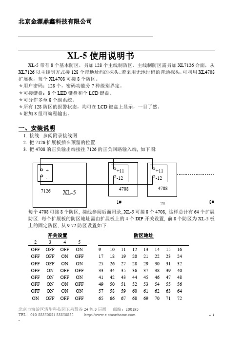
NOT RDY: ZNE 13
MASTER BEDROOM
3.留守开机
按(STAY)键,接着按密码,显示屏会显示:
ON: STAY
4.瞬时模式开机:
按【INSTANT】接着按密码,这时显示屏会显示:
问题054快速布防能力
对于系统用户是否快速布防命令《#1》是有用的。
问题055快速强制布防
对于系统用户是否快速强制布防命令《#2》是有用的。
问题056
问题057
问题058对于系统用户是否快速旁路命令《#5》是有用的
问题059对于系统用户是否可以通过键盘命令《#6》打开或关闭系统钟声
问题060是否具有权艰1的用户能够改变系统所有副系统内用户副系统的设定
问题011第2报警中心奇偶校验选择
问题012
问题013安装密码
问题014拔号方式
问题015
问题016控制箱的中心拔号功能
问题017是否允许控制箱遥控操作
问题018遥控撤防能力
问题019遥控布防能力
问题020遥控旁路能力
问题021最多拔号次数
问题022震铃次数
问题023
问题024控制箱等待中心接收机承认的时间
#3+11+INSTAT+21+CODE+INSTANT+12+INSTANT+21+INSTANT+92.
退出按※.
11.进入编程方法:【CODE】+※+安装密码+6种状态(安装密码: 123456)
6种状态分别为:
1.
键盘编程
2.
时间/日期编程
3.
步行测试
4.
自动喷水灭火系统 第 2 部分:湿式报警阀、延迟器、水力警铃说明书

ICS13.220.30CCS C84中华人民共和国国家标准GB5135.2—20XX代替GB5135.2-2003自动喷水灭火系统第2部分:湿式报警阀、延迟器、水力警铃Automatic sprinkler system—Part2:Wet system alarm valves、retard chamber、water motor alarm征求意见稿20XX-XX-XX发布20XX-XX-XX实施国家市场监督管理总局前 言本文件的全部技术内容为强制性。
本文件按照GB/T1.1—2020《标准化工作导则第1部分:标准化文件的结构和起草规则》和GB/T 20001.10—2014《标准编写规则第10部分:产品标准》的规定起草。
本文件是GB5135《自动喷水灭火系统》的第2部分。
GB5135已经发布了以下部分:——第1部分:洒水喷头;——第2部分:湿式报警阀、延迟器和水力警铃;——第3部分:水雾喷头;——第4部分:干式报警阀;——第5部分:雨淋报警阀;——第6部分:通用阀门;——第7部分:水流指示器;——第8部分:加速器;——第9部分:早期抑制快速响应(ESFR)喷头;——第10部分:压力开关;——第11部分:沟槽式管接件;——第13部分:水幕喷头;——第14部分:预作用装置;——第15部分:家用喷头;——第16部分:消防洒水软管;——第17部分:减压阀;——第18部分:消防管道支吊架;——第19部分:塑料管道及管件;——第20部分:涂覆钢管;——第21部分:末端试水装置;——第22部分:特殊应用喷头。
本文件代替GB5135.2-2003《自动喷水灭火系统第2部分:湿式报警阀、延迟器和水力警铃》。
与GB5135.2—2003相比,除编辑性改动外,主要技术变化如下:——更改了规范性引用文件(见第2章,2003年版的第2章);——更改了部分术语和定义(见第3.2、3.8、3.9,2003年版的3.2、3.8、3.9);——增加了产品的分类与代号、型号编制(见第4章、第5章);——更改了标志(见6.1.2,2003年版的4.1.2);——更改了规格(见6.2,2003年版的4.2.2);——更改了额定工作压力(见6.3,2003年版的4.2.1)——更改了“材料耐腐蚀性”(见6.4,2003年版的4.3);——更改了结构(见6.5.1,2003年版的4.4.1);——更改了“连接方式”(见6.6,2003年版的4.4.3);——对“零部件”要求进行了更改,增加了阀瓣密封件(见6.7、6.8,2003年版的4.5.4);——更改了“水力摩阻”(见6.12,2003年版的4.9);——更改了“功能”(见6.13,2003年版的4.10);——更改了“水力警铃”(见6.18,2003版的4.15、4.16、4.17);——增加了部分“要求”所对应的“试验方法”(见第七章);——更改了附录A(见附录A,2003年版的附录A);——删除了附录B(见2003年版的附录B)请注意本文件的某些内容可能涉及专利。
Eaton ROLPSB SV 火警设备- 室内使用声音报警器说明说明书
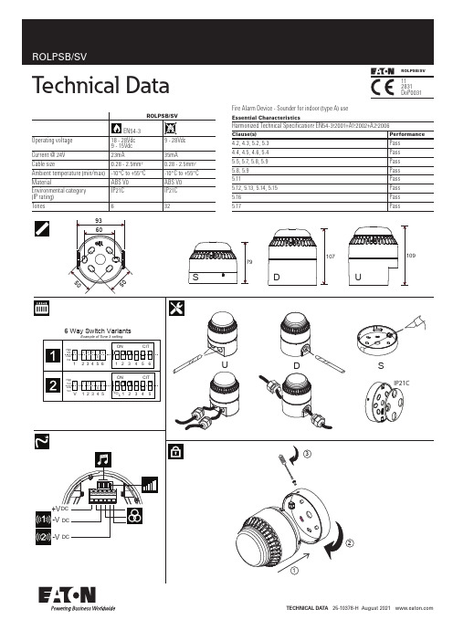
Technical DataTechnical DaTa 25-10378-H August 2021 S 107D UFire Alarm Device - Sounder for indoor (type A) useEssential CharacteristicsHarmonized Technical Specification: EN54-3:2001+A1:2002+A2:2006Clause(s)Performance4.2, 4.3,5.2, 5.3 Pass 4.4, 4.5, 4.6, 5.4 Pass 5.5, 5.7, 5.8, 5.9 Pass 5.8, 5.9Pass 5.11Pass 5.12, 5.13, 5.14, 5.15Pass 5.16Pass 5.17PassTechnical DataeatonEMEA Headquarters Route de la Longeraie 71110 Morges, Switzerland Eaton.euTEL: +44 (0) 1302 321541FAX: +44 (0) 1302 303220********************************************© 2021 EatonAll Rights ReservedEaton is a registered trademark.All trademarks are property of their respective Eaton Electrical Products Ltd.Llantarnam Park Cwmbran NP44 3AWTel: +44 (0) 1633 628500Fax: +44 (0) 1633 866346in the column marked EN54-3II.All other SPL measurements are taken ‘on axis’ & are not third party verified.III. Detailed EN54-3 polar SPL measurements are available in M96-024IV. A SPL of at least 65dB(A) is achieved in at least one direction at minimum volume/voltage.I. Les tons certifiés dans le cadre de la RPC (application alarme incendie) sont indiqués dans la colonne intitulée EN54-3.II. Toutes les autres mesures NPA sont relevées « sur axe » et ne sont pas vérifiées par un tiers.III. Les mesures NPA polaires détaillées EN54-3 sont disponibles dans M96-024I. Die nach CPR (Feuermelderanwendung) zertifizierten Töne sind in Spalte EN54-3.II.Alle anderen Schalldruckmessungen wurden vom akustischen Mittelpunkt ab gelesen und von keiner unabhängigen Stelle verifiziert.III. Detaillierte Polar-SPL -Messungen gemäß EN54-3 sind erhältlich in M96-024I. I toni della sirena certificati CPR (applicazione allarme antincendio) sono indicate nella colonna contrassegnata con EN54-3.II.Tutte le altre misurazioni SPL sono state rilevate “sull’asse” e non sono state verificate da terzi.III. Le misurazioni SPL polari ai sensi della norma EN54-3 sono disponibili in M96-024kolom waar EN54-3 staat vermeld.II. Alle andere SPL -afmetingen zijn via de ‘as’ gedaan en niet door derden geverifieerd.III. Uitgebreide polaire SPL -afmetingen voor EN54-3 zijn beschikbaar in M96-024I. Los sonidos certificados por el CPR (aplicación para alarmas de incendios) se muestran en la columna marcada con EN54-3.II.Cualquier otra medida del SPL (nivel de intensidad acústica) se toma “sobre el eje” y no está verificada por terceras partes.III. Las medidas detalladas del SPL polar EN54-3 están disponibles en M96-024I. Signaler som är certifierade för CPR (brandvarnare) visas i kolumnen märkt EN54-3.II.Alla övriga mätningar av ljudtrycket har genomförts “direkt intill” och är inte bekräftade av tredje part.III. Detaljerade polära mätningar av ljudtrycket enligt EN54-3 finns under M96-024I. Sygnały d źwiękowe zgodne z CPR (do zastosowań pożarowych) wskazane są w kolumnie EN54-3.II.Pomiary SPL wszystkich pozostałych sygnałów zostały wykonane …w osi” i nie były poddane weryfikacji przez stronę trzecią.III. Szczegółowe dane pomiarów kątowych SPL wg EN54-3 dostępnesą w dokumencie M96-024.。
Cooper Notification UTA-1 电话警报器使用说明书
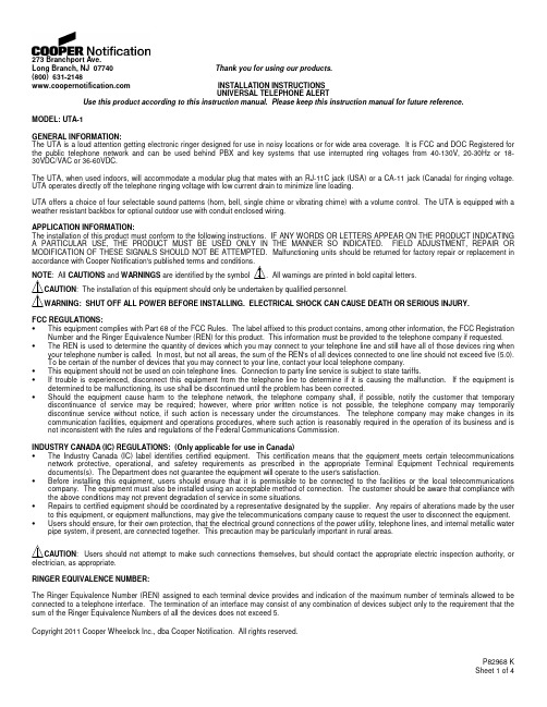
273 Branchport Ave.Long Branch, NJ 07740 Thank you for using our products.(800) 631-2148 INSTALLATION INSTRUCTIONSUNIVERSAL TELEPHONE ALERTUse this product according to this instruction manual. Please keep this instruction manual for future reference.MODEL: UTA-1GENERAL INFORMATION:The UTA is a loud attention getting electronic ringer designed for use in noisy locations or for wide area coverage. It is FCC and DOC Registered for the public telephone network and can be used behind PBX and key systems that use interrupted ring voltages from 40-130V, 20-30Hz or 18-30VDC/VAC or 36-60VDC.The UTA, when used indoors, will accommodate a modular plug that mates with an RJ-11C jack (USA) or a CA-11 jack (Canada) for ringing voltage. UTA operates directly off the telephone ringing voltage with low current drain to minimize line loading.UTA offers a choice of four selectable sound patterns (horn, bell, single chime or vibrating chime) with a volume control. The UTA is equipped with a weather resistant backbox for optional outdoor use with conduit enclosed wiring.APPLICATION INFORMATION:The installation of this product must conform to the following instructions. IF ANY WORDS OR LETTERS APPEAR ON THE PRODUCT INDICATING A PARTICULAR USE, THE PRODUCT MUST BE USED ONLY IN THE MANNER SO INDICATED. FIELD ADJUSTMENT, REPAIR OR MODIFICATION OF THESE SIGNALS SHOULD NOT BE ATTEMPTED. Malfunctioning units should be returned for factory repair or replacement inCAUTIONS and WARNINGS: The installation of this equipment should only be undertaken by qualified personnel.FCC REGULATIONS:•This equipment complies with Part 68 of the FCC Rules. The label affixed to this product contains, among other information, the FCC Registration Number and the Ringer Equivalence Number (REN) for this product. This information must be provided to the telephone company if requested. •The REN is used to determine the quantity of devices which you may connect to your telephone line and still have all of those devices ring when your telephone number is called. In most, but not all areas, the sum of the REN's of all devices connected to one line should not exceed five (5.0).To be certain of the number of devices that you may connect to your line, contact your local telephone company.•This equipment should not be used on coin telephone lines. Connection to party line service is subject to state tariffs.•If trouble is experienced, disconnect this equipment from the telephone line to determine if it is causing the malfunction. If the equipment is determined to be malfunctioning, its use shall be discontinued until the problem has been corrected.•Should the equipment cause harm to the telephone network, the telephone company shall, if possible, notify the customer that temporary discontinuance of service may be required; however, where prior written notice is not possible, the telephone company may temporarily discontinue service without notice, if such action is necessary under the circumstances. The telephone company may make changes in its communication facilities, equipment and operations procedures, where such action is reasonably required in the operation of its business and is not inconsistent with the rules and regulations of the Federal Communications Commission.INDUSTRY CANADA (IC) REGULATIONS: (Only applicable for use in Canada)•The Industry Canada (IC) label identifies certified equipment. This certification means that the equipment meets certain telecommunications network protective, operational, and safetey requirements as prescribed in the appropriate Terminal Equipment Technical requirements documents(s). The Department does not guarantee the equipment will operate to the user's satisfaction.•Before installing this equipment, users should ensure that it is permissible to be connected to the facilities or the local telecommunications company. The equipment must also be installed using an acceptable method of connection. The customer should be aware that compliance with the above conditions may not prevent degradation of service in some situations.•Repairs to certified equipment should be coordinated by a representative designated by the supplier. Any repairs of alterations made by the user to this equipment, or equipment malfunctions, may give the telecommunications company cause to request the user to disconnect the equipment. •Users should ensure, for their own protection, that the electrical ground connections of the power utility, telephone lines, and internal metallic water pipe system, if present, are connected together. This precaution may be particularly important in rural areas.: Users should not attempt to make such connections themselves, but should contact the appropriate electric inspection authority, orRINGER EQUIVALENCE NUMBER:The Ringer Equivalence Number (REN) assigned to each terminal device provides and indication of the maximum number of terminals allowed to be connected to a telephone interface. The termination of an interface may consist of any combination of devices subject only to the requirement that the sum of the Ringer Equivalence Numbers of all the devices does not exceed 5.Copyright 2011 Cooper Wheelock Inc., dba Cooper Notification. All rights reserved.SPECIFICATIONS:Table 1: Sound Output (dBA) and Current (REN) at Maximum Volume24VDC 24VAC 48VDC 90Vrms/20Hz Horn 108dB/30mA 105dB/46mA 107dB/26mA 104dB/No More 1.6 RENBell 100dB/9mA 102dB/35mA 100dB/10mA 100dB/ No More 1.4 RENVibrating Chime 96dB/6mA 99dB/29mA 94dB/7mA 97dB/ No More 1.25 RENSingle Chime 96dB/6mA 100dB/34mA 94dB/6mA 96dB/ No More 1.25 REN NOTES:1. Input Voltage Range: 24VDC = 18-30VDC, 24VAC = 18-30VAC, 48VDC = 36-60VDC, 90VRMS =40-130VRMS, 20-30Hz2. dBA is measured on-axis in a non-reflective (free field) test room using fast meter response.Table 2: Sound Output Volume Adjusting Range24VDC 24VAC 48VDC 90Vrms/20Hz Horn 108-73dB 105-76dB 107-79dB 104-83dBBell 100-61dB 102-64dB 100-67dB 100-73dBVibrating Chime 97-57dB 100-61dB 94-64dB 97-68dBSingle Chime 96-57dB 97-61dB 94-64dB 96-68dBTable 3: Tone DescriptionHorn Broadband HornBell 1560Hz Modulated (0.07 Sec. ON/RepeatVibrating Chime 700Hz (1.0 Sec. Decay/Repeat)Single Chime 700Hz (1.0 Sec. Decay)Table 4: Duty and Ring CycleCycle 90Vrms/20-30Hz 24VDC/AC, 48VDCDuty Cycle 33% Max. 100% Max.Min. Ring Cycle ON Time 0.8 Sec. 0.5 Sec.Min. Ring Cycle OFF Time 1.6 Sec. 0.5 Sec.Max. Ring Cycle ON Time 10 Sec. ContinuesUTA SETTINGS:The SW1 and SW2 switches of the UTA are used to set input voltage and desired tone as shown in Figure 2 and Table 5. The potentiometer R12 (shown in Figure 2) is used to adjust the volume of sound.The factory settings are:Input Voltage = 90Vrms/20-30Hz (SW1 POS 1 set on 0)Tone = Horn (SW2 POS 1,2,3,4 set on 0,0,1,1)Volume = MaximumTable 5: Input Voltage and Tone SelectionsSwitch SettingsInput Tone SW1 SW2Voltage POS 1 POS 1 POS 2 POS 3 POS 4Horn 1 1 0 1 124VDC Bell 1 1 0 1 0Vibrating Chime 1 1 0 0 0Single Chime 1 1 1 0 1Horn 1 0 0 1 124VAC Bell 1 1 0 1 0Vibrating Chime 1 1 0 0 0Single Chime 1 1 1 0 1Horn 1 0 0 1 148VDC Bell 1 0 0 1 0Vibrating Chime 1 0 0 0 0Single Chime 1 0 1 0 1Horn 0 0 0 1 190VAC Bell 0 0 0 1 020-30Hz Vibrating Chime 0 0 0 0 0Single Chime 0 0 1 0 1MOUNTING INFORMATION:The UTA is designed for mounting to walls, partitions or posts in both indoor and outdoor applications. Refer to Figures 1, 2 and 3 mounting, wiring and adjustment of each model. Use 4 conductor modular telephone line cords for ring voltage indoor wiring. For outdoor applications, use conduit enclosed wiring. All models are rated for indoor and outdoor use with a temperature range of -31°F to +150°F (-35°C to +66°C) and a maximum humidity of 95% RH.NOTE: Potentiometer shaft and four screws must be installed first before proceeding with Figure 1.Before mounting, test the signal by temporarily connecting it as shown. Place a call into the system to make sure the signal operates properly.HARMFUL TO YOUR HEARING. UTA’s SHOULD BE LOCATED AT LEAST 10 FEET AWAY FROM LISTENERS.mounting screw (supplied) as per diagram"bottom" hole. Tighten both screws. Forhollow or thin panels use appropriate drywall fastenersImproper connections and settings can damage the unit and/or the phone system.These devices are not intended for use in hazardous locations as defined by the National Electrical Code (NEC) and by the National ANY MATERIAL EXTRAPOLATED FROM THIS DOCUMENT OR FROM COOPER NOTIFICATION MANUALS OR OTHER DOCUMENTS DESCRIBING THE PRODUCT FOR USE IN PROMOTIONAL OR ADVERTISING CLAIMS, OR FOR ANY OTHER USE, INCLUDING DESCRIPTION OF THE PRODUCT'S APPLICATION, OPERATION, INSTALLATION AND TESTING IS USED AT THE SOLE RISK OF THE USER AND COOPER NOTIFICATION WILL NOT HAVE ANY LIABILITY FOR SUCH USE.Check the installation instructions of the manufacturers of other equipment used in the system for any guidelines or restrictions on example, may require special precautions to assure electrical noise immunity (e.g. audio crosstalk).NOTE: This equipment has been tested and found to comply with the limits for a Class B digital device, pursuant to Part 15 of the FCC Rules. These limits are designed to provide reasonable protection against harmful interference in residential installation. This equipment generates, uses and can radiate radio frequency energy and, if not installed and used in accordance with the instructions, may cause harmful interference to radio communications. However, there is no guarantee that interference will not occur in a particular installation. If this equipment does cause harmful interference to radio or television reception, which can be determined by turning the equipment off and on, the user is encouraged to try to correct the interference by one or more of the following measures: 1) Reorient or relocate the receiving antenna, 2) Increase the separation between the equipment and receiver, 3) Connect the equipment into an outlet on a circuit different from that to which the receiver is connected, and 4) Consult the dealer or an experienced radio/TV technician for help.LIMITED WARRANTYCooper Wheelock, Inc. dba Cooper Notification and Cooper Notification, Inc. (each, a “Seller”) products must be used within their published specifications and must be PROPERLY specified, applied, installed, operated, maintained and operationally tested in accordance with these instructions at the time of installation and at least twice a year or more often and in accordance with local, state and federal codes, regulations and laws. Specification, application, installation, operation, maintenance and testing must be performed by qualified personnel for proper operation in accordance with all of the latest National Fire Protection Association (NFPA), Underwriter’s Laboratories (UL), National Electrical Code (NEC), Occupational Safety and Health Administration (OSHA), local, state, county, province, district, federal and other applicable building and fire standards, guidelines, regulations laws and codes including, but not limited to, all appendices and amendments and the requirements of the local authority having jurisdiction (AHJ). Seller products when properly specified, applied, installed, operated, maintained and operationally tested as provided above are warranted against mechanical and electrical defects for a period of (a) three (3) years from date of manufacture with respect to MEDC and Seller Industrial Signals and Seller Fire and Security Notification Appliances and Devices, or (b) one (1) year from date of manufacture with respect to Waves and SafePath Voice Evacuation and Mass Notification Systems (date of manufacture is determined by date code.) Correction of defects by repair or replacement shall be at Seller’s sole discretion and shall constitute fulfillment of all obligations under this warranty. THE FOREGOING LIMITED WARRANTY SHALL IMMEDIATELY TERMINATE IN THE EVENT ANY PART NOT FURNISHED BY SELLER IS INSTALLED IN THE PRODUCT. THE FOREGOING LIMITED WARRANTY SPECIFICALLY EXCLUDES ANY SOFTWARE REQUIRED FOR THE OPERATION OF OR INCLUDED IN A PRODUCT. SELLER MAKES NO REPRESENTATION OR WARRANTY OF ANY OTHER KIND, EXPRESS, IMPLIED OR STATUTORY WHETHER AS TO MECHANTABILITY, FITNESS FOR A PARTICULAR PURPOSE OR ANY OTHER MATTER.USERS ARE SOLELY RESPONSIBLE FOR DETERMINING WHETHER A PRODUCT IS SUITABLE FOR THE USER’S PURPOSES, OR WHETHER IT WILL ACHIEVE THE USER’S INTENDED RESULTS. THERE IS NO WARRANTY AGAINST DAMAGE RESULTING FROM MISAPPLIACATION, IMPROPER SPECIFICATION, ABUSE, ACCIDENT OR OTHER OPERATING CONDITIONS BEYOND SELLER’S CONTROL.SELLER DOES NOT WARRANT THAT THE OPERATION OF THE SOFTWARE WILL BE UNINTERRUPTED OR ERROR-FREE OR THAT THE SOFTWARE WILL MEET ANY OTHER STANDARD OF PERFORMANCE, OR THAT THE FUNCTIONS OR PERFORMANCE OF THE SOFTWARE WILL MEET THE USER’S REQUIREMENTS. SELLER SHALL NOT BE LIABLE FOR ANY DELAYS, BREAKDOWNS, INTERRUPTIONS, LOSS, DESTRUCTION, ALTERATION, OR OTHER PROBLEMS IN THE USE OF A PRODUCT ARISING OUT OF OR CAUSED BY THE SOFTWARE.THE LIABILITY OF SELLER ARISING OUT OF THE SUPPLYING OF A PRODUCT, OR ITS USE, WHETHER ON WARRANTIES, NEGLIGENCE, OR OTHERWISE, SHALL NOT IN ANY CASE EXCEED THE COST OF CORRECTING DEFECTS AS STATED IN THE LIMITED WARRANTY AND UPON EXPIRATION OF THE WARRANTY PERIOD ALL SUCH LIABILITY SHALL TERMINATE. SELLER IS NOT LIABLE FOR LABOR COSTS INCURRED IN REMOVAL, REINSTALLATION OR REPAIR OF A PRODUCT BY ANYONE OTHER THAN SELLER OR FOR DAMAGE OF ANY TYPE WHATSOEVER, INCLUDING BUT NOT LIMITED TO, LOSS OF PROFIT OR INCIDENTAL, INDIRECT, CONSEQUENTIAL, SPECIAL, PUNTIVE OR EXEMPLARY DAMAGES. THE FOREGOING SHALL CONSTITUTE THE SOLE REMEDY OF THE PURCHASER AND THE EXCLUSIVE LIABILITY OF SELLER.IN NO CASE WILL SELLER’S LIABILITY EXCEED THE PURCHASE PRICE PAID FOR A PRODUCT.LIMITATION OF LIABILITYSELLER’S LIABILITY ON ANY CLAIM OF ANY KIND, INCLUDING NEGLIGENCE AND BREACH OF WARRNTY, FOR ANY LOSS OR DAMAGE RESULTING FROM, ARISING OUT OF, OR CONNECTED WITH THIS CONTRACT, OR FROM THE MANUFACTURE, SALE, DELIVERY, RESALE, REPAIR OR USE OF ANY PRODUCT COVERED BY THIS ORDER SHALL BE LIMITED TO THE PRICE APPLICABLE TO THE PRODUCT OR PART THEREOF WHICH GIVES RISE TO THE CLAIM. SELLER’S LIABILITY ON ANY CLAIM OF ANY KIND SHALL CEASE IMMEDIATELY UPON THE INSTALLATION IN THE PRODUCT OF ANY PART NOT FURNISHED BY SELLER. IN NO EVENT SHALL SELLER BE LIABLE FOR ANY CLAIM OF ANY KIND UNLESS IT IS PROVEN THAT ITS PRODUCT WAS THE DIRECT CAUSE OF SUCH CLAIM. FURTHER, IN NO EVENT, INCLUDING IN THE CASE OF A CLAIM OF NEGLIGENCE, SHALL SELLER BE LIABLE FOR INCIDENTAL, INDIRECT, CONSEQUENTIAL, SPECIAL, PUNITIVE OR EXEMPLARY DAMAGES. SOME STATES DO NOT ALLOW THE EXCLUSION OR LIMITATION OF INCIDENTAL OR CONSEQUENTIAL DAMAGES, SO THE PRECEDING LIMITATION MAY NOT APPLY TO ALL PURCHASERS.8/11。
幼儿园安全警报器使用指南:教学手册
幼儿园安全警报器使用指南:教学手册幼儿园安全警报器使用指南:教学手册随着幼儿园教育的不断发展,幼儿园安全成为了备受关注的话题。
在幼儿园中,安全警报器的使用至关重要,它可以在紧急情况下及时提醒教职员工和家长们,确保幼儿园的安全。
本文将深入探讨幼儿园安全警报器的使用指南,为教职员工提供专业的教学手册。
一、规范使用准则1. 对警报器的基本了解在教学手册中,必须首先对安全警报器的基本原理和使用方法进行介绍。
工作人员在紧急情况下应该如何触发警报器,以及触发后应该采取的措施,这些都是必不可少的知识。
2. 规范操作流程教学手册需要详细列出警报器的操作流程,包括启动警报器、紧急联系人的通知、学生疏散的指导等。
规范的操作流程可以有效提高应急反应的效率,保障幼儿园在紧急情况下的安全。
二、训练与演练1. 定期演练安全警报器的使用需要进行定期的演练,以确保教职员工能够熟练掌握操作流程。
在教学手册中可以列出演练的时间表和具体内容,例如模拟火灾、自然灾害等紧急情况,让工作人员能够快速而准确地进行应对。
2. 演练记录和总结每次演练后都需要对演练情况进行记录和总结,教学手册应当详细描述记录的形式和内容。
通过记录和总结,可以及时发现问题,并及时进行纠正和改进,提高教职员工的应急处置能力。
三、现场应用实例1. 分类应用教学手册可以提供各种紧急情况下的现场应用实例,例如火灾、入侵、自然灾害等。
在面对不同的紧急情况时,工作人员应该采取对应的操作流程和措施,因此现场应用实例的提供对于教职员工的应急反应能力提升至关重要。
2. 成功案例与失败案例通过共享成功的应用案例和失败的案例,教学手册可以帮助教职员工更好地理解警报器的使用,并且警示工作人员应该注意哪些问题。
这种实例的共享和讨论可以帮助工作人员更好地理解如何正确、高效地使用安全警报器。
个人观点和理解在我看来,幼儿园安全警报器的使用是非常重要的。
作为工作人员,我们必须时刻保持警惕,掌握安全警报器的使用方法,并且要通过定期的演练和总结,不断提高自身的应急处理能力。
警铃组使用说明书
总动员警铃系统使用说明书广州航海仪器厂有限公司 2010.031.使用注意事项1.1 连接电缆应使用屏蔽双绞线,电源线和信号线不能接反,否则会导致设备的损毁。
1.2 总动员警铃系统在不使用时,应关闭电源开关,以免设备在不工作的状态下长期受电。
1.3 使用本设备之前,务必详细阅读设备说明书或操作手册,熟悉掌握设备的使用要求。
维修设备时,也应参考说明书的指示意见。
2.设备简介2.1概述总动员警铃系统是用于发布舰船内紧急动员信令和报警信令,系统设6个编码遥控器。
启动任何一个编码遥控器都可以控制全船总动员警铃,并发出《海军舰艇条例》规定的音响信号,完成全船紧急动员任务;当接到火灾报警开关信号时,全船总动员系统发出报警信号。
报警信令能分别向船员和保障人员以及向两都同时发出。
2.2 组成本总动员警铃系统是由6个总动员警铃编码遥控器、1个总动员警铃主控制器、7个总动员警铃分线箱、5个红色信号灯、56个电铃和210个鸣音器组成。
设备详细清单见表1:表13.主要性能指标3.1 技术参数3.1.1工作电源:主电源 AC220V应急电源 DC220V功率≤ 4.2KW3.1.2 防护等级: IP22/IP563.2 使用环境条件3.2.1 环境温度:-25~55°C3.2.2空气相对湿度≤95%3.2.3 倾斜和摇摆:横摇±15O、横倾±22.5O纵摇±10O 纵倾±10O3.2.4船舶正常航行中所产生的振动和冲击;4.系统基本工作原理和主要功能4.1 基本工作原理本系统是由两路电源供电,主电源为AC220V,应急电源为DC220V。
主电源经过整流转换为DC220V,一方面给报警电铃供电,另一方面给控制系统供电。
该系统设置了电源电动切换功能电路,当主电源AC220正常时系统使用AC220V工作,当主电源AC220V失电时系统自动转换至应急电源DC220V供电,并且输出一组无源触点信号至驾控台电源故障报警板。
时钟型99防区语音报警器说明书

全功能无线数码智能安防报警系统使用说明书系统简介:本系统为新一代的家用/商用全兼容的安防报警系统,报警主机和配件之间完全无线连接,安装方便。
采用全新的百万组无线编码技术,保密性强。
当有人非法闯入时,主机会发出警报。
同时拨打主人的电话或手机。
配合烟雾感应器和燃气感应器可以防止火灾发生和燃气泄漏。
广泛应用于家庭,商铺,工厂、学校、别墅等区域。
功能特点:◆99个无线防区,每个防区均可独立工作,可设置多达9种工作模式。
◆报警时自动拨打用户设置的6组电话号码;兼容200电话及IP电话。
◆语音留言功能和语音播报防区功能相结合。
◆支持远程异地监听、电话布防、撤防及阻吓功能及独有的远程查询功能。
◆智能学习各种无线配件,快捷方便,兼容2262及百万组编码。
方便用户扩展功能。
◆停电报警功能,停电后主机可以拨打预设的电话号码,通知用户;用户也可远程查询家里的是否停电。
◆内置高精度定时芯片,具有九组定时功能。
可以定制布防,撤防或设置成闹钟;更具有独有的整点报时功能。
断电后时间设置不消失。
◆超强的语音查询功能,可以查询设置的各组电话号码、最近的报警记录、防区类型、定时设置等。
◆全程语音指导,用户操作及远程控制时更方便。
◆全功能设计。
本系统内置迎宾器,门铃和呼叫器功能。
适合各种商业用途。
门磁安装:用随机配备的双面胶把磁条贴在门上,门磁感应器贴在门框上。
安装时注意讲磁条装在门磁感应器有LED指示灯的一侧。
两者对齐。
间距小于1厘米。
若门磁欠压指示灯长亮表示电池电压不足,需要更换电池。
红外安装:红外感应器的原理是感应人体发出的红外线信号,探测人体的移动。
感应距离随着环境温度的变化通常为5-12米。
夏天温度高,感应距离会变近。
冬天温度低,感应距离远。
红外感应器通常安装在离地面2米左右的位置,对准需要探测的区域。
红外感应器只能装在室内。
不要对着太阳光、窗户、空调等温度快速变化的地方。
红外感应器需要在启动3-5分钟后进入稳定状态。
快速使用:主机的基本操作:遥控器布防及撤防:主人离家外出时按遥控器上的“布防”键设防,主机进入工作状态。
EATON ULCF3000 火警和声音报警系统指南说明书

Features and benefits • Large versatile touch-screen user interface • 2 or 4 Class A Style 7 SLC loops • Event history buffer (9,999 events) with date/time stamp• 4 Notification appliance circuit (NAC’s) outputs • Dedicated alarm, trouble, AC trouble relays • Integral short circuit isolators • Up to 200 addresses per loop • Full network capability up to 126 panels • Supports a comprehensive range of soft addressing modules and devices for greater flexibility in design • Menu driven graphical user interface for ease of operation• Reduced commissioning time through soft addressing and auto learn functions• Programming and trouble shooting time minimised by using a range of features such as auto config, walk test, system details menusThe Eaton ULCF3000 is a high specification intelligent addressable, wall or rack mounted, UL Listed control panel available in various loop configurations. It combines sophisticated functionality with simple operation and aesthetically pleasing design.The control panel has the ability to support complex cause and effect programming (via site installer) and a wide range of user controllable functions that make the panel ideal for a diverse range of projects from industrial applications through to large multi site commercial developments.The ULCF3000 uses soft addressing to minimise installation time and remove the potential for error associated with manual addressing. It can operate as a stand alone panel or as part of a networked system, and has powerful programming options that allow configurable control over whether messages from specific panels are transmitted around the network or remain local.ULCF3000 (wall mount graphite)ULCF3000RM (wall mount red metal)EATON - SPECIFIER’S GUIDE - FIRE AND VOICE ALARM SYSTEMS SGTEXT ©February 2015T echnical specificationCatalogue numbers Dimensions Code ULCF3000 / ULCF3000RMDescription UL intelligent addressable control panel Standards UL864 9th editionPrimary operating supply 120V ac / 240V ac, 60Hz, 2.0A supervised Secondary operating supplyBattery voltage 24V dcBattery charge current 1.0A (max)Battery derating factor 0.1Battery capacity supervised 12Ah (max)Notification appliance circuits Class B, Style Y , Sounder Group 1, Sound-er 1, Sounder Group 1, Sounder 2, Sounder Group 2Output voltage 24V dcOutput current 0.75A (max)Line impedance 50ΩWhen powered by 240V ac, the maximum current of 3.0A is shared between these circuits When powered by 120V ac, the maximum current of 2.25A is shared between these circuits Circuits are supervised, power limited and regulated.Notification appliance circuits Class B, Style Y , SYNC MODULE. NAC1, NAC2Output voltage 24V dcOutput current 0.5A (max)Line impedance 50Ω (max)The maximum current of 0.5A is shared between these circuits Circuits are supervised, power limited and regulated.Alarm, trouble contacts. Relay expansionUnity power factor 30V dc For connection to power limited sources only Aux relay (AC T rouble) contactsUnity power factor 30V dc, 1A For connection to power limited sources only Signaling line circuit Style [7] Class [A] – (Addressable Loop)Rated voltage 24V dcMaximum current 500mALine impedance 50Ω (max)Supervised, power limitedNetwork SLCVoltage 5V dcCurrent 100mA (max)Line impedance 50Ω (max)Power limited Limited to same enclosure installations PhysicalIP Rating IP30CompatibilitySuitable for use with Eaton UL fire systemsD2W H D1Description H (mm)W (mm)D1 (mm)D2 (mm)ULCF300039749775130ULCF3000RM 39850548118D2W H D1Description Code 2 loop panel ULCF30002G 4 loop panel ULCF30004G 2 loop panel, integral printer ULCF30002GP 4 loop panel, integral printer ULCF30004GP 2 loop panel, network card ULCF30002GNC 4 loop panel, network card ULCF30004GNC 2 loop panel, integral printer, network card ULCF30002GPNC 4 loop panel, integral printer, network card ULCF30004GPNC 2 loop panel, red metal box ULCF30002GRM 4 loop panel, red metal box ULCF30004GRM 2 loop panel, integral printer, red metal box ULCF30002GPRM 4 loop panel, integral printer, red metal box ULCF30004GPRM 2 loop panel, network card, red metal box ULCF30002GNCRM 4 loop panel, network card, red metal box ULCF30004GNCRM 2 loop panel, integral printer, network card, red metal box ULCF30002GPNCRM 4 loop panel, integral printer, network card, red metal box ULCF30004GPNCRM Rack mounted 2 loop panel ULR3000L2Rack mounted 4 loop panel ULR3000L4Rack mounted 2 loop panel c/w network card ULR3000L2NC Rack mounted 4 loop panel c/w network card ULR3000L4NC Loop connected repeater panel ULCF3000PRG Touchscreen network repeater panel ULCTPR3000Control Panel 1Control Panel 2PSU Site Graphics System PA/VA System BATT Printer BMS System Interface System block diagram ULCF3000(wall mount graphite)ULCF3000RM (wall mount red metal)Specifier’s guide3.2 Control panels。
联动警铃逃生应急演练-概述说明以及解释
联动警铃逃生应急演练-概述说明以及解释1.引言1.1 概述概述部分的内容可以描述联动警铃逃生应急演练的背景和基本情况。
以下是一个示例:概述部分:联动警铃逃生应急演练是一种针对突发灾害和紧急情况的训练活动,旨在提高人们在危险环境下的自救和逃生能力。
在现代社会,各种灾害和事故频繁发生,特别是火灾、地震等突发事件,给社会带来了严重的伤害和损失。
因此,及时而有效的应急预案和逃生措施显得尤为重要。
联动警铃逃生应急演练是一种应对紧急情况的训练方法,通过利用警铃联动系统,迅速发布预警信息,提醒人们采取适当的应急措施和执行逃生计划。
当警铃联动触发时,可以自动触发其他环境设备,如疏散门、疏散指示灯等,为人们提供更加清晰和明确的逃生指引。
本文旨在详细讨论联动警铃逃生应急演练的作用、重要性以及实施步骤。
通过深入分析联动警铃逃生应急演练的效果和方法,可以进一步完善这一训练机制,提高人们的应急能力,并强调逃生应急演练的必要性和持续性。
在接下来的章节中,我们将详细介绍联动警铃的作用,阐述逃生应急演练的重要性,并提供实施联动警铃逃生应急演练的具体步骤。
最后,我们将总结联动警铃逃生应急演练的效果,探讨进一步完善这一训练方法的途径,并强调逃生应急演练在我们日常生活中的必要性和持续性。
通过阅读本文,您将对联动警铃逃生应急演练有更加深入的了解,为应对突发灾害和紧急情况提供有力支持。
1.2文章结构文章结构部分的内容如下:1.2 文章结构本篇文章将分为引言、正文和结论三个部分来阐述联动警铃逃生应急演练的重要性和实施步骤。
引言部分将在概述联动警铃逃生应急演练的基本概念和背景的基础上,介绍文章的结构和目的。
正文部分将重点探讨两个关键方面。
首先,我们将阐述联动警铃在应急情况下的作用,包括它如何提醒人们及时采取行动以保护自己的生命安全。
其次,我们将深入探讨逃生应急演练的重要性,包括为什么每个人都应该参与演练以提高应对紧急情况的能力。
在讨论完联动警铃的作用和逃生应急演练的重要性后,我们将详细介绍实施联动警铃逃生应急演练的步骤。
霍尼韦尔238C说明书
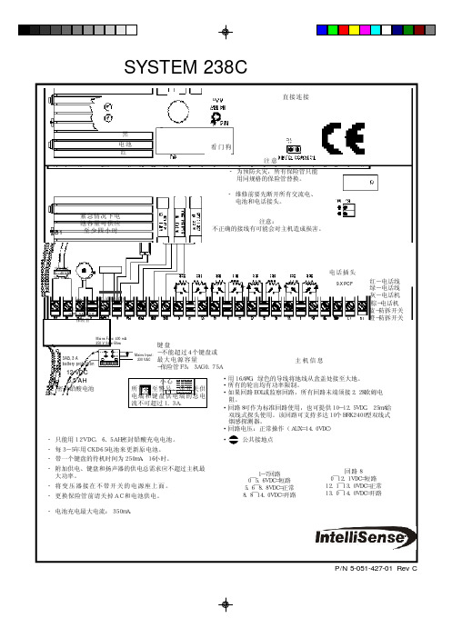
SYSTEM 238C 安装手册-为预防火灾,所有保险管只能 用同规格的保险管替换。
-维修前要先断开所有交流电、 电池和电话接头。
黑电池红看门狗直接连接紧急情况下电池容量可供应至少四小时注意:不正确的接线有可能会对主机造成损害。
红-电话线绿-电话线灰-电话机棕-电话机 蓝-防拆开关 橙-防拆开关电话插头主机信息·用16AWG,绿色的导线将地线从盒盖处接至大地。
·所有的轮出均有功率限制。
密封铅酸电池 小心所有接至警号、带开关供可关断的电源警铃SYSTEM 238C-TL Installation Manual2内容System 238C 接线图 内容安装2控制主机接线 2 - 4系统上电 4键盘设置 4键盘编址 4厂家缺省编程4 - 5编程项目(字母序)5主机编程5 - 6使用LED键盘编程 6使用ALPHA键盘编程 6输入十六进制数 6对ALPHA键盘编程6 - 7显示信息编程 7编程模板7编程项目(数字顺序)8 - 19键盘标签20电话线路问题20看门狗指示灯20键盘操作命令概述21常见问题解答22 - 23如何减少误报 24 - 25系统限制26保修事宜26编程表格27 - 28范围本手册主要介绍SYSTEM238C安装与编程的基本方法。
若要进一步了解系统的使用及编程,请参阅LED键盘手册,ALPHA键盘手册,或者Commander II/MonitorII操作手册。
手册使用说明准确性本手册已经审阅以保证其准确性。
然而对于用户在使用过程中由于对手册内容的误解、误操作而导致任何后果,INTELLISENSE有权对238C的硬件、软件和手册作进一步修改。
固定机箱238C应该装在便于接入交流电源,电话线和地线的位置上。
从机箱中取出电路板,这样可以避免在机箱上鉴开预留孔时损坏电路板。
鉴开预留孔在墙上标志螺丝安装孔;把控制主机安装在需要的高度上,并把电线穿过预留孔;装回电路板,并固定好,切记在电路板的左下角接上地线焊 片。
电铃说明书
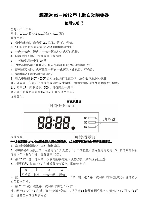
超速达CS-9812型电脑自动响铃器使用说明书型号:CS-9812尺寸:260mm(长)×180mm(宽)×50mm(厚)功能简介:1、微电脑控制,高亮度LED显示,清晰,明亮。
2、24小时内最多可设置40次不同的响铃时间。
3、铃声分长声、短声、一长一短三种方式可供选择。
4、响铃时间长短在99秒内可任意选择。
5、计时精度月差小于20秒。
6、内置高性能可充电电池,保证外部断电后20小时数据记忆。
7、既可每天响铃,也可设置一周内一或两天(休息日)不响铃。
8、紧急情况下可手动控制响铃。
9、输入电压在160V~230V之间仪器均能可靠工作,适合低电压地区使用。
10、设有输出保险,当外接负载短路或过载时,保险将熔断以对内部电路进行保护。
11、功率2W,耗电极小,500小时仅耗约一度电。
12、输出负载功率为220V/3A,可并接多个电铃。
面板说明:面板示意图操作步骤:***本仪器请勿与其他用电器共用电源插座,以免因干扰使响铃程序出现紊乱。
1、将响铃器电源接入220V 市电插座。
2、将响铃器后面板上的“内置电池”开关置于“开”的位置,使内置电池充电。
3、按动响铃器后面板上的“复位”键,屏幕显示。
4、按“S1”键,进入第一次响铃的响铃方式设置状态,屏幕显示。
5、对照下表,按动“S3 ”键设置末位数字,即响铃方式。
6、按“S2”键,进入第一次响铃时间设置状态,屏幕显示时位数字闪动。
7、按“S3”键,设置第一次响铃时间之“小时”。
注:若持续按住“S3”键,数字将快速变动。
(以下当S3键用作调整数字时相向。
)8、再按“S2”键,屏幕显示分位数字闪动。
9、按“S3”键,设置第一次响铃时间之“分”。
10、按“S1”键,存入第一次响铃的设置,同时进入第二次响铃的响铃方式设置状态,屏幕显示11、重复5 -10 步,设置第二、三、…次响铃的响铃方式及晌铃时向,直到将所需要的多次响铃的响铃方式和响铃时间全部设置完毕并存入,此时屏幕显示为第一次响铃的响铃方式设置状态,用户可不必设置,直接进入下一步。
Whelen 警笛产品说明书
©2007 Whelen Engineering Company Inc.Form No.14120A (043008)A u t o m o t i v e : S i r e n s /S w i t c h e sFor warranty information regarding this product, visit /warrantyDANGER! Sirens produce extremely loud emergency warning tones! Exposure to these tones without proper and adequate hearing protection, could cause ear damage and/or hearing loss! The Occupational Safety & Health Administration () provides information necessary to determine safe exposure times in Occupational Noise Exposure Section 1910.95. Until you have determined the safe exposure times for your specific application,operators and anyone else in the immediate vicinity should be required to wear an approved hearing protection device. Failure to follow this recommendation could cause hearing loss!•Proper installation of this product requires the installer to have a good understanding of automotive electronics, systems and procedures.•Whelen Engineering requires the use of waterproof butt splices and/or connectors if that connector could be exposed to moisture.•Any holes, either created or utilized by this product, should be made both air- and watertight using a sealant recommended by your vehicle manufacturer.•Failure to use specified installation parts and/or hardware will void the product warranty.•If mounting this product requires drilling holes, the installer MUST be sure that no vehicle components or other vital parts could be damaged by the drilling process. Check both sides of the mounting surface before drilling begins. Also de-burr the holes and remove any metal shards or remnants. Install grommets into all wire passage holes.•If this manual states that this product may be mounted with suction cups, magnets, tape or Velcro®, clean the mounting surface with a 50/50 mix of isopropyl alcohol and water and dry thoroughly.•Do not install this product or route any wires in the deployment area of your air bag. Equipment mounted or located in the air bag deployment area will damage or reduce the effectiveness of the air bag, or become a projectile that could cause serious personal injury or death. Refer to your vehicle owner’s manual for the air bag deployment area. The User/Installer assumes full responsibility to determine proper mounting location, based on providing ultimate safety to all passengers inside the vehicle.•For this product to operate at optimum efficiency, a good electrical connection to chassis ground must be made. The recommended procedure requires the product ground wire to be connected directly to the NEGATIVE (-) battery post (this does not include products that use cigar power cords).•If this product uses a remote device for activation or control, make sure that this device is located in an area that allows both the vehicle and the device to be operated safely in any driving condition.•It is recommended that these instructions be stored in a safe place and referred to when performing maintenance and/or reinstallation of this product.•FAILURE TO FOLLOW THESE SAFETY PRECAUTIONS AND INSTRUCTIONS COULD RESULT IN DAMAGE TO THE PRODUCT OR VEHICLE AND/OR SERIOUS INJURY TO YOU AND YOUR PASSENGERS!CAUTIONLoud siren noise can cause hearing damage and/or loss.Refer to OSHA Section 1910.95prior to putting ANY siren into service!Wear Protection!ACTIVATION OF THIS SIREN MAY DAMAGE UNPROTECTED EARS!Warnings to InstallersWhelen’s emergency vehicle warning devices must be properly mounted and wired in order to be effective and safe. Read and follow all of Whelen’s written instructions when installing or using this device. Emergency vehicles are often operated under high speed stressful conditions which must be accounted for when installing all emergency warning devices. Controls should be placed within convenient reach of the operator so that they can operate the system without taking their eyes off the roadway. Emergency warning devices can require high electrical voltages and/or currents. Properly protect and use caution around live electrical connections.Grounding or shorting of electrical connections can cause high current arcing, which can cause personal injury and/or vehicle damage, including fire. Many electronic devices used in emergency vehicles can create or be affected by electromagnetic interference. Therefore, after installation of any electronic device it is necessary to test all electronic equipment simultaneously to insure that they operate free of interference from other components within the vehicle. Never power emergency warning equipment from the same circuit or share the same grounding circuit with radio communication equipment. All devices should be mounted in accordance with the manufacturer’s instructions and securely fastened to vehicle elements of sufficient strength to withstand the forces applied to the device. Driver and/or passenger air bags (SRS) will affect the way equipment should be mounted. This device should be mounted by permanent installation and within the zones specified by the vehicle manufacturer, if any. Any device mounted in the deployment area of an air bag will damage or reduce the effectiveness of the air bag and may damage or dislodge the device. Installer must be sure that this device, its mounting hardware and electrical supply wiring does not interfere with the air bag or the SRS wiring or sensors. Mounting the unit inside the vehicle by a method other than permanent installation is not recommended as unit may become dislodged during swerving; sudden braking or collision. Failure to follow instructions can result in personal injury. Whelen assumes no liability for any loss resulting from the use of this warning device. PROPER INSTALLATION COMBINED WITH OPERATOR TRAINING IN THE PROPER USE OF EMERGENCY WARNING DEVICES IS ESSENTIAL TO INSURE THE SAFETY OF EMERGENCY PERSONNEL AND THE PUBLIC.Warnings to UsersWhelen’s emergency vehicle warning devices are intended to alert other operators and pedestrians to the presence and operation of emergency vehicles and personnel. However, the use of this or any other Whelen emergency warning device does not guarantee that you will have the right-of-way or that other drivers and pedestrians will properly heed an emergency warning signal. Never assume you have the right-of-way. It is your responsibility to proceed safely before entering an intersection, driving against traffic, responding at a high rate of speed, or walking on or around traffic lanes. Emergency vehicle warning devices should be tested on a daily basis to ensure that they operate properly. When in actual use, the operator must ensure that both visual and audible warnings are not blocked by vehicle components (i.e.: open trunks or compartment doors), people, vehicles, or other obstructions. It is the user’s responsibility to understand and obey all laws regarding emergency warning devices. The user should be familiar with all applicable laws and regulations prior to the use of any emergency vehicle warning device. Whelen’s audible warning devices are designed to project sound in a forward direction away from the vehicle occupants. However, because sustained periodic exposure to loud sounds can cause hearing loss, all audible warning devices should be installed and operated in accordance with the standards established by the National Fire Protection Association.Safety FirstThis document provides all the necessary information to allow your Whelen product to be properly and safely installed. Before beginning the installation and/or operation of your new product, the installation technician and operator must read this manual completely. Important information is contained herein that could prevent serious injury or damage.Installation Guide:SA315 Siren Speaker Bracket2005-07 Ford 500Kit# SAK2251 Winthrop RoadChester, Connecticut 06412-0684Phone: (860) 526-9504Internet: Sales e-mail: autosale@Customer Service e-mail: custserv@®ENGINEERING COMPANY INC.5/16-181/2"DIA.HEX NUTFig.45/16-18X 1-1/4"HEX HEAD BOLT WIDEN THESE HOLES FOR THE 5/16BOLTS5/16"SPLIT LOCKWASHERUSE EXISTING BOLT FROM VEHICLE HEREFig.3from M O U T I N GS UR F A CE.325"LONG X.625"OUTER DIAMETERMounting locationViewed bottomFig.2Fig.1The SA315siren speaker mounting kit comes with 3long bolts (1/4-20X necessary to go through the mounting bracket,through the siren housing of the 4shorter bolts (“A”)that now secure the siren driver to the speaker more of the shorter bolts installed.A short bolt be used in the hole that properly secure the driver to the housing.If you need to remove all 4bolts must passage hole1/4-20X 1-1/2"HEX HEAD SS (Speaker &Bracket)1/4"SPLIT LOCK WASHERSA315L A R G E SPACERS5/16S P L I T LOCK WASHER5/16-181/2"DIA.HEX NUTS M A L L SPACER1/4LONG X 1/2"OUTR.DIA.1/4"CLEARANCE Installation:NOTE: Figure 1 shows the mounting location of the speaker bracket with the front of the vehicle removed for visual reference. You do not need to remove any parts from the vehicle. You will only need to lower the front gravel shield to make this installation.1.To access the speaker bracket mounting area, remove the clips holding thefront bottom gravel shield and lower the front of the shield (refer to the vehicle service manual for the recommended procedure).NOTE: Do not mount this bracket on the passenger-side of the vehicle.2.With the gravel shield lowered, locate the mounting area (Fig. 1). The “tab” thatprotrudes from the side of the bracket will be secured to the vehicle using an existing bolt (Fig. 3). The top of the bracket will mount to two existing holes in a metal support on the vehicle. IMPORTANT NOTE FOR 2007 MODELS ONLY:On 2007 models these holes must be enlarged to accomodate the 5/16bolts. Before installing, position the bracket in its mounting area and locate the three mounting holes you will use.3.Secure the speaker to the bracket using the supplied hardware.IMPORTANT! For drainage purposes, the speaker must be oriented so that the wire passage/drain hole is in the “6 o’clock” position (closest to the road).Improper mounting will result in premature driver failure and void the product warranty.4.Remove the existing bolt that will be used to secure the “tab” on the bracket to the vehicle. Secure the upper part of the bracket to the vehicle using the two existing holes with the hardware shown. The backside of the mounting holes can be accessed allowing the nuts to be held in place while installing the bolts and spacers. Tighten the mounting hardware firmly.5.Secure the side of the siren bracket to the vehicle using the bolt removed in step 4 and the small spacer provided.6.Extend the WHITE (positive) and BLACK (negative) speaker wires to your siren amplifier and connect as shown in the amplifiers instructions. Test siren to confirm proper operation.Permanent mounting of this product will require drilling. It is absolutely necessary to make sure that no other vehicle components could be damaged by this process. Check both sides of the mounting surface before starting. If damage is likely, select a different mounting location.MPORTANT! Before you return this vehicle to active service, visually confirm the proper operation of this product, and all vehicle components/equipment.CAUTIONACTIVATION OF THISSIREN MAY DAMAGE UNPROTECTED EARS!。
警铃组使用说明书

总动员警铃系统使用说明书广州航海仪器厂有限公司2010.031.使用注意事项1.1 连接电缆应使用屏蔽双绞线,电源线和信号线不能接反,否则会导致设备的损毁。
1.2 总动员警铃系统在不使用时,应关闭电源开关,以免设备在不工作的状态下长期受电。
1.3 使用本设备之前,务必详细阅读设备说明书或操作手册,熟悉掌握设备的使用要求。
维修设备时,也应参考说明书的指示意见。
2.设备简介2.1概述总动员警铃系统是用于发布舰船内紧急动员信令和报警信令,系统设6个编码遥控器。
启动任何一个编码遥控器都可以控制全船总动员警铃,并发出《海军舰艇条例》规定的音响信号,完成全船紧急动员任务;当接到火灾报警开关信号时,全船总动员系统发出报警信号。
报警信令能分别向船员和保障人员以及向两都同时发出。
2.2 组成本总动员警铃系统是由6个总动员警铃编码遥控器、1个总动员警铃主控制器、7个总动员警铃分线箱、5个红色信号灯、56个电铃和210个鸣音器组成。
设备详细清单见表1:表13.主要性能指标3.1 技术参数3.1.1工作电源:主电源 AC220V应急电源 DC220V功率≤ 4.2KW3.1.2 防护等级:IP22/IP563.2 使用环境条件3.2.1 环境温度:-25~55°C3.2.2空气相对湿度≤95%3.2.3 倾斜和摇摆:横摇±15O、横倾±22.5O纵摇±10O 纵倾±10O3.2.4船舶正常航行中所产生的振动和冲击;4.系统基本工作原理和主要功能4.1 基本工作原理本系统是由两路电源供电,主电源为AC220V,应急电源为DC220V。
主电源经过整流转换为DC220V,一方面给报警电铃供电,另一方面给控制系统供电。
该系统设置了电源电动切换功能电路,当主电源AC220正常时系统使用AC220V工作,当主电源AC220V失电时系统自动转换至应急电源DC220V供电,并且输出一组无源触点信号至驾控台电源故障报警板。
电铃使用说明书
1、概述目前在皮带运输巷和提升运输巷使用的信号装置大致有两类,一类是传统的隔爆型电磁式电铃;另一类是组合式声光信号电铃,其中有一些具有单工对讲功能。
后者在技术和功能上都有了较大发展,但要实现多水平信号区分、二级传送、安全灯自动转换等功能仍需要增设大量电缆及隔爆型三通、四通等,投资大、故障率高。
针对目前这种状况,我们研制生产了KXT23型数显通信声光信号装置。
该产品结构上为隔爆兼本安型设计,采用单片微控制器及调制解调技术,仅需一条四芯信号电缆,即能实现发出声、光信号、单工对讲、自动区分多水平、二级传送、红绿灯转换等功能。
技术领先、设计合理、一机多用。
可应用于皮带机巷和轨道运输巷,是目前声光信号装置中理想的更新换代产品。
2、主要技术参数3、主要功能3.1、发出声光信号、数显打点数功能在等机状态下,按下信号装置的“信号按钮”,联线上的各装置,均发出声光信号,并数字显示打点数(二级传送除外)。
3.2、自动实现二级传送功能将车房内的信号装置,设置为二级传送状态(将DTP2开关中“1”拨到数字侧,“2”拨到ON侧),井口发出打点信号时,车房及其它水平相应发出声光信号,并显示打点数;当其它水平打点时,车房内的信号装置,只有灯光及数字显示,而不发出打点声,也无127V电压输出,无须使用双联按钮,自动实现二级传送。
3.3、对讲呼叫功能在待机状态下,可实现单工对讲及呼叫功能。
按下信号装置对讲按钮,联线的所有信号装置均能听到讲话及呼叫,松开对讲按钮,信号装置均处于接收状态。
注:在绞车运行时,应禁止对讲呼叫,以免影响司机操作。
3.4、多水平数显功能将每台信号装置设置一个编码(如井口为“1”,一水平为“2”,车房不设置等),按下信号装置“信号按钮”后,其它所有联机装置都数显打点位置的编码,同时根据编码的不同而发出不同的音调,无须增加任何电缆及设备,自动实现多水平的信号区分。
3.5、安全灯自动转换功能在轨道运输中当绞车起动时,可对车房内信号装置输入36V电压信号或工作闸继电器常开接点信号,每个水平都可自动实现安全灯转换,而无需重新架设电缆。
- 1、下载文档前请自行甄别文档内容的完整性,平台不提供额外的编辑、内容补充、找答案等附加服务。
- 2、"仅部分预览"的文档,不可在线预览部分如存在完整性等问题,可反馈申请退款(可完整预览的文档不适用该条件!)。
- 3、如文档侵犯您的权益,请联系客服反馈,我们会尽快为您处理(人工客服工作时间:9:00-18:30)。
总动员警铃系统使用说明书
广州航海仪器厂有限公司
2010.03
1.使用注意事项
1.1 连接电缆应使用屏蔽双绞线,电源线和信号线不能接反,否则会导致设备的损毁。
1.2 总动员警铃系统在不使用时,应关闭电源开关,以免设备在不工作的状态下长期受电。
1.3 使用本设备之前,务必详细阅读设备说明书或操作手册,熟悉掌握设备的使用要求。
维修设备时,也应参考说明书的指示意见。
2.设备简介
2.1概述
总动员警铃系统是用于发布舰船内紧急动员信令和报警信令,系统设6个编码遥控器。
启动任何一个编码遥控器都可以控制全船总动员警铃,并发出《海军舰艇条例》规定的音响信号,完成全船紧急动员任务;当接到火灾报警开关信号时,全船总动员系统发出报警信号。
报警信令能分别向船员和保障人员以及向两都同时发出。
2.2 组成
本总动员警铃系统是由6个总动员警铃编码遥控器、1个总动员警铃主控制器、7个总动员警铃分线箱、5个红色信号灯、56个电铃和210个鸣音器组成。
设备详细清单见表1:
表1
3.主要性能指标
3.1 技术参数
3.1.1工作电源:
主电源 AC220V
应急电源 DC220V
功率≤ 4.2KW
3.1.2 防护等级:IP22/IP56
3.2 使用环境条件
3.2.1 环境温度:
-25~55°C
3.2.2空气相对湿度
≤95%
3.2.3 倾斜和摇摆:
横摇±15O、横倾±22.5O
纵摇±10O 纵倾±10O
3.2.4船舶正常航行中所产生的振动和冲击;
4.系统基本工作原理和主要功能
4.1 基本工作原理
本系统是由两路电源供电,主电源为AC220V,应急电源为DC220V。
主电源经过整流转换为DC220V,一方面给报警电铃供电,另一方面给控制系统供电。
该系统设置了电源电动切换功能电路,当主电源AC220正常时系统使用AC220V工作,当主电源AC220V失电时系统自动转换至应急电源DC220V供电,并且输出一组无源触点信号至驾控台电源故障报警板。
本系统是由多个Microchip系列CPU组成的控制系统,其中编码器和主控制器里面有各自的CPU控制,并且相互之间通过数据线连接进行数据的发送和接收。
编码器负责完成信令传递、接收和报警信令指示功能;主控制器负责编码器的巡检、失电报警和完成报警信号的输出功能。
主控制器分时与每个编码器进行数据通信,当其中一路编码器有报警信令发布时,主控制器将收到来自该编码器的信令,首先主控制器将报警信令发送至所有的编码器,编码器收到信令后,点亮对应的报警信令指示灯。
同时主控制器启动固态继电器接通电铃进行报警,并且向主机舱组合报警箱和辅机舱组合报警箱各提供一路无源触点,触点闭合状态与当前报警制式相同。
4.2 主要功能
4.2.1电源自动切换
总动员警铃系统设有电源自动切换功能,正常工作时使用主电源AC220V,当主电源失电时系统自动切换至应急电源DC220V供电。
当主电源恢复正常时,系统自动切换至主电源供电。
4.2.2 报警信号输出
本系统提供七组报警接点输出,每组接点分别由不同的固态继电器控制,每组接点最大外接电流为10A。
主控制器还向主机舱组合报警箱和辅机舱组合报警箱提供两组无源触点输出,触点闭合状态与报警制式相同。
4.2.3 火灾信号
系统提供火灾信号无源触点输入,当收到火灾开关闭合信号时,将发出连续报警信令,此信号不能用消除键清除,并此时系统的所有信令键的操作不能被识别,只有当火灾信号消失后才能停止。
4.2.5编码遥控器自动检测
本系统能够对编码遥控器的工作状态进行自动检测, 编码遥控器正常工作时,编码遥控器面板上的通信指示灯常亮,当该编码遥控器出现故障时, 面板上的通信指示灯闪烁,以表示编码遥控器通信出现故障。
待故障排除后,指示灯变回平光表示编码遥控器恢复正常。
4.2.6信令发布对象选择功能
本系统能分别或同时向船员或保障人员发出报警信令。
通过操作编码遥控器发布对象选择开关,选择信令发布的对象是船员、保障人员或全体人员。
4.2.7 自动工作方式
接通电源后系统自动进入自动工作状态,此时按动编码遥控器上的信令键,编码遥控器该信令指示灯指示信令状态,主控制器控制板控制相应的固态继电器,带动外接电铃发出紧急动员信令和报警信令。
4.2.8 编码器互锁功能
当系统处于报警状态时,系统将自动屏蔽所有编码器上的信令键,此时按
动任意编码器上的信令键都不能发出报警信令。
4.2.9 手动工作方式
本系统设有手动功能,手动功能不需要CPU控制,通过按动编码遥控器上的”手动”键,直接控制所有外接报警电铃,发布紧急动员信令和报警信令。
如果系统处于自动状态,按下”手动”键将终止自动报警状态,并清除自动报警信息。
当松开“手动”键5秒后,系统自动重新进入自动工作方式状态。
4.2.10 消除
当系统处于某一信令自动报警状态时,可通过按动任意一编码遥控器上的”消除”键或”手动”键终止当前信令状态。
5.使用说明
通过操作安装在驾控台、船长办公室、值班室、登艇处、损管控制室等的编码遥控器向主控制器发送报警信令,然后由主控制器驱动外接电铃发出舰船内紧急动员信令和报警信令、所有的信令方式均符合标准GJB623A-98《舰艇声光信号统一规定》中规定的报警和信令制式。
5.1设备待命状态
首先检查设备接线是否正确无误,然后按下主控制器的电源开关按键,给总动员警铃系统供电,些时主控制器的电源指示灯点亮,各编码遥控器的指示灯点亮,各路编码器遥控器与主控制器通信正常,则系统工作正常并进入待命状态。
5.2发布报警信令
当系统不处于报警状态时,如果需要发布报警或紧急动员信令,首先按下发布对象选择开关选择信令发布的对象是全体人员、船员或者保障人员,
然后按下编码遥控器面板上相应的报警信令开关,则所有编码遥控器相应的报警信令指示灯点亮,主控制器驱动相应发布对象的外接电铃发出相应的报警信号。
当该报警信令时序执行完毕后,所有的编码遥控器上相应的报警信令指示灯熄灭,主控制器停止驱动电铃报警,本次报警操作完成。
所有报警信令的时序必须与表3中的信令时序相一致。
本系统设有10种报警信令、五种控制功能及一个备用功能,报警信令的详细内容见表3:
表3
5.3 清除信令
当系统正处于自动报警状态时,要清除当前报警信令或进行其它报警信令操作,则必须按下编码遥控器的“清除”键,才能清除当前报警信令。
5.4 手动报警
当需要进行手动报警发布信令时,按下编码遥控器面板上的“手动”键,则直接驱动外接电铃鸣响进行报警。
6.安装
6.1 验收产品
当收到设备时,应先检查包装是否完整无损,资料是否完整,若发现问题应及时与厂商联系。
如果产品暂不安装使用,则应存放于干燥、通风良好的库房中。
6.2 设备的安装
用螺钉将产品固定于正常工作位置,安装过程中应避免剧烈碰撞,以免人为损坏设备。
安装完毕后,应检查元件是否牢固可靠,并测量其对地绝缘电阻,应不小于100兆欧。
6.4 设备的连接
设备应按照随机文件的系统接线图进行连接,接线过程中应避免将电源线和信号线混淆接反,否则会导致设备的损毁,连接电缆应使用屏蔽双绞线(推荐选用JHQYJP80/SC屏蔽双绞线或CHJPJ85/SC 2X2X1)。
连接完毕后应将
连接线固定于扎线条上,并对连接线进行检查,是否有错接或漏接。
7、维修事项
7.1、当总动员警铃系统出现故障影响使用功能时,应及时维修、维修工作应由合格的专业人员或经指定的人员负责进行。
7.2、当总动员警铃系统现不能工作的故障时,应首先检查供电状况是否良好,重点查找配电系统的元件是否工作正常,接线是否完整等,还应在电源线的端子处检查外供的电源是否正常。
7.3凡需更换的当总动员警铃系统的元件,应注意选用型号相符的器件。