5.22重烃分离器技术规格书
22分离器计量及维修保养操作规程(gai)

作业指导书
风城油田作业区分离器计量及维修保养操作规程
文件编号:XYFZ/QHSE-CZ [201] 122-2008
版号:B
修改状态:1
编制:李建军、李新海、安琪、杨松柏
审核:
批准:
1范围
本标准规定了稠油热采立式分离器计量及维修保养安装操作规程;
本标准适用于稠油热采立式计量分离器的计量及维修保养工作。
2分离器计量操作规程
2.l检查进出口闸门,设备有无渗漏,检查玻璃管上、下流闸门是否打开,检查分离器出口是否关闭;
2.2开该井分离器闸门,关该井进罐闸门;
2.3待液面升到下触点时记录时间,待液面上升到上触点时再次记录时间;
2.4改流程,开该井进罐闸门,关进分离器闸门;
2.5检查输油流程,关大罐出口闸门,打开分离器出口闸门;
2.6检查流程,盘泵,启泵将液位打到下触点10cm以下,停泵;
2.7关分离器出口闸门,打开大罐出口闸门;
2.8再检查一次流程,正常后方可离开。
3.分离器维修保养操作规程。
3.1分离器必须按规程使用,严禁超负荷使用;
3.2分离器每月进行一次保养;
3.2.1检查分离器各部件有无渗漏,并对各闸门尽心保养、维护;
3.2.2紧固分离器各部件螺丝;
3.2.3清洗量油玻璃管;
3.2.4清洗水包,并更换水包内的余水;
3.2.5检查分离器放空管线和排污管线是否堵塞并进行吹扫疏通;
3.2.6擦洗分离器,整体见本色;
3.3分离器每月定期排污一次,每年检查积砂情况,对积砂较多的分离器要及时,清砂。
4.相关文件。
环保无损排气的压缩空气凝集油水分离器说明书
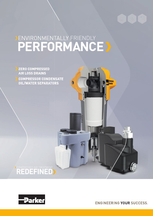
ENVIRONMENTALLY FRIENDLY ENVIRONMENTALLY FR PERFORMANCECOMPRESSED AIR TREATMENT REDEFINEDThe challenge is to remove harmful condensate without losing valuable compressed air . However , popular timed solenoid drains are often simply set up and forgotten about. If the timing system is not adjusted to open according to seasonal temperature and load variation, the drain will either waste a significant amount of air in winter; or there could be condensate carryover in summer , resulting in poor quality air .This inefficient drainage process leads to costly compressed air leaks. For example, typical air loss from a timed solenoid drain set to open 5 seconds every 10 minutes can equate to 1m³/hr . That uses approximately 0.10Kw of energy every hour, equating to as much as 873Kw per drain per year , with an environmental impact equivalent to 463kg/CO 2.EFFECTIVE PERFORMANCEGuaranteed to retain all of the compressed air within the system, Parker zero loss condensate drains provide a return on investment within 12 months. Minimal maintenance and downtime, high effi ciency, proven reliability and longer operational life combine to ensure a lower total cost of ownership compared to manual and timed drain solutions.PERFORMANCE Whilst designed to work as an integral component of ouradvanced air treatment systems, Parker OIL-X filters arealso a drop-in replacement for the OIL-X Plus, and are fullyretro-compatible with a wide range of drying equipment.Zero compressed air lossV alidated filtration performance, meeting classificationsshown within ISO8573-1 compressed air standardsL ow differential pressureL ow total cost of ownership with extendedequipment lifespanThe fl oat drain never runs completely dry, only opening when enough condensate is present. This ensures no valuable compressed air is lost during the discharge process – increasing the overall effi ciency of the whole compressed air system.Zero compressed air lossLarge discharge orifice minimises the chance of blockages Zero air loss during discharge ensures no emulsion is created Manual override valve for functional checksEasy to install – no power supply, programming or calibration requiredEFFICIENTPERFORMANCEDesigned for higher capacity condensate needs, they use internal sensors to determine the exact moment to discharge condensate, resulting in a reduced number of switching cycles – maximizing the service life of the drain valve. Zero compressed air lossIntegrated strainer with alarm monitoring for increased process safety Large discharge orifi ce minimizes the chance of blockagesEasy to install and service – no programming or calibration requiredThe Parker ES2000 oil/water separator is designed to keep you on the right side of waste regulation. It’s the most cost-effective solution – ensuring full compliance through safe and effi cient on-site oil disposal. Environmentally friendlyEffi ciently separates oil and water on-site and returnsup to 99.9% of the condensate to foul sewersLarge oil-absorbing pre-fi lter(s) protect carbon stagefrom bulk contaminationLarge carbon stage for increased contact time,improving water quality and extending carbon lifeAllows users to meet discharge regulations,and to achieve ISO14001 certifi cationRapid payback over conventional disposal methodsEasy to install, operate and maintainAll Parker fl oat and level sensing drains are zero air loss.Highly effi cient drainage with minimal downtime fora lower total cost of ownership.Reliable drainage and disposal increases theeffi ciency of the whole compressed air system.The environmentally friendly ES2000 ensures compliance with oil disposal regulations.Discover how Parker’s drainage and oil/water separation solutions can improve your system effi ciency for longer. Visit /GSFEWHAT NEXT?Europe, Middle East, AfricaAE – United Arab Emirates, DubaiTel: +971 4 8127100 ********************AT – Austria, Wiener Neustadt Tel: +43 (0)2622 23501-0 *************************AT – Eastern Europe, Wiener NeustadtTel: +43 (0)2622 23501 900 ****************************AZ – Azerbaijan, Baku Tel: +994 50 2233 458****************************BE/LU – Belgium, Nivelles Tel: +32 (0)67 280 900*************************BG – Bulgaria, Sofia Tel: +359 2 980 1344**************************BY – Belarus, Minsk Tel: +48 (0)22 573 24 00 ************************CH – Switzerland, Etoy Tel: +41 (0)21 821 87 00*****************************CZ – Czech Republic, Klecany Tel: +420 284 083 111*******************************DE – Germany, Kaarst Tel: +49 (0)2131 4016 0*************************DK – Denmark, Ballerup Tel: +45 43 56 04 00*************************ES – Spain, Madrid Tel: +34 902 330 001 ***********************FI – Finland, Vantaa Tel: +358 (0)20 753 2500 *************************FR – France, Contamine s/Arve Tel: +33 (0)4 50 25 80 25 ************************GR – Greece, Athens Tel: +30 210 933 6450 ************************HU – Hungary, Budaörs Tel: +36 23 885 470*************************IE – Ireland, Dublin Tel: +353 (0)1 466 6370 *************************IL – IsraelTel: +39 02 45 19 21************************IT – Italy, Corsico (MI) Tel: +39 02 45 19 21 ***********************KZ – Kazakhstan, Almaty Tel: +7 7273 561 000****************************NL – The Netherlands, Oldenzaal Tel: +31 (0)541 585 000 ********************NO – Norway, Asker Tel: +47 66 75 34 00************************PL – Poland, Warsaw Tel: +48 (0)22 573 24 00 ************************PT – PortugalTel: +351 22 999 7360**************************RO – Romania, Bucharest Tel: +40 21 252 1382*************************RU – Russia, Moscow Tel: +7 495 645-2156************************SE – Sweden, Spånga Tel: +46 (0)8 59 79 50 00 ************************SK – Slovakia, Banská Bystrica Tel: +421 484 162 252**************************SL – Slovenia, Novo Mesto Tel: +386 7 337 6650**************************TR – Turkey, Istanbul Tel: +90 216 4997081 ************************UA – Ukraine, Kiev Tel: +48 (0)22 573 24 00 ************************UK – United Kingdom, Warwick Tel: +44 (0)1926 317 878 ********************ZA – South Africa, Kempton Park Tel: +27 (0)11 961 0700*****************************North AmericaCA – Canada, Milton, Ontario Tel: +1 905 693 3000US – USA, Cleveland Tel: +1 216 896 3000Asia PacificAU – Australia, Castle Hill Tel: +61 (0)2-9634 7777CN – China, Shanghai Tel: +86 21 2899 5000HK – Hong Kong Tel: +852 2428 8008IN – India, MumbaiTel: +91 22 6513 7081-85JP – Japan, Tokyo Tel: +81 (0)3 6408 3901KR – South Korea, Seoul Tel: +82 2 559 0400MY – Malaysia, Shah Alam Tel: +60 3 7849 0800NZ – New Zealand, Mt Wellington Tel: +64 9 574 1744SG – Singapore Tel: +65 6887 6300TH – Thailand, Bangkok Tel: +662 186 7000TW – Taiwan, Taipei Tel: +886 2 2298 8987South AmericaAR – Argentina, Buenos Aires Tel: +54 3327 44 4129BR – Brazil, Sao Jose dos Campos Tel: +55 800 727 5374 CL – Chile, Santiago Tel: +56 2 623 1216MX – Mexico, Toluca Tel: +52 72 2275 4200BROCONDENSATE-00-ENYour local authorized Parker distributor© 2018 Parker Hannifin Corporation. All rights reserved.Parker WorldwideEuropean Product Information Centre Free phone: 00 800 27 27 5374(from AT, BE, CH, CZ, DE, DK, EE, ES, FI, FR, IE, IL, IS, IT, LU, MT, NL, NO, PL, PT, RU, SE, SK, UK, ZA)EMEA Product Information Centre Free phone: 00 800 27 27 5374(from AT , BE, CH, CZ, DE, DK, EE, ES, FI, FR, IE, IL, IS, IT , LU, MT , NL, NO, PL, PT , RU, SE, SK, UK, ZA) US Product Information Centre Toll-free number: 1-800-27 27 537/gsfe。
分离器技术规格书4-24
中油股份乌鲁木齐石化公司热电厂烟气脱硫装置一、二效分离室制作技术规格书乌石化公司热电厂:乌石化公司:二〇一三年一月目录一、总则二、自然条件和公用工程条件三、工艺参数四、设计、制造过程中执行的标准和规范五、供货清单六、技术要求七、检验与验收八、图纸和资料交付九、涂色、标识和包装十、性能保证十一、质量保证与技术服务十二、交货期十三、报价说明十四、其它一、总则1.1本技术规格书适用于中国石油乌鲁木齐石化公司(简称买方)和宝鸡宝冶钛镍制造有限责任公司(简称卖方)就买方热电厂烟气脱硫装置一、二效分离器制作的有关技术事宜,本技术规格书是商务合同的重要组成部分。
在商务合同生效后,本技术规格书作为商务合同的附件,与商务合同具有同等的法律效力。
★1.2本技术规格书提出的是最低限度的技术要求,并未对一切技术细节做出规定,也未充分引述有关标准和规范的条文,卖方应保证提供符合本技术规格书和有关最新工业标准的成熟的优质产品。
#1.3如卖方没有以书面形式对本技术规格书的条文提出异议,则意味着卖方提供的设备完全符合本技术规格书的要求。
如有异议,卖方应以书面形式或电子邮件形式向买方提出,经双方协商达成一致意见后方可变更。
#1.4在签订商务合同之后,买方保留对本技术规格书提出补充要求和修改的权力,卖方承诺予以配合,具体事宜由双方商定。
★1.5卖方作为总成套方,对于产品涉及到的所有设备和设施起总成负责作用,卖方保证对其提供设备的完整性负责。
二、自然条件现场条件年平均气温: 16.6℃最高月平均气温: 25.7 ℃最低月平均气温: -14.8 ℃极端最高气温: 42 ℃极端最低气温: -41.5℃年平均气压: 950.2mba最高绝对大气压: 988.7mba最低绝对大气压: 924.4mba年平均相对湿度: 60%月最大相对湿度: 82%月最小相对湿度: 39%基本风压(10米高处):0.6kN/m2最大月平均风速: 2.9m/s三、工艺参数★设备工艺参数其他设计条件见图纸。
浓缩版燃油 水分离器说明书

• Installation • Operation • Parts• Service Information150 SERIESDiesel Fuel/Water SeparatorsMODEL 150 23NOTE: The bowl should always be drained before water orcontaminant levels reach the bottom of the depressurizer cone. Check daily with the engine off. Always open the draincock completely to flush particulates out. Failure to do so could cause a leaky valve.A. DAHL Units Mounted HIGHER Than Fuel Storage Tank 1. Turn engine off.2. Open the primer plug to vent the filter and then open the draincock to drain all contaminants.d rAining wAter ___________________________________________________SERVICING3. Close the draincock and follow the priming instructions shown below.B. DAHL Units Mounted LOWER Than Fuel Storage Tank 1. Turn engine off and close shut-off valve. (Valved Manifold units may be drained and elements replaced with the engine running at idle. Close inlet and outlet valves to isolate the filter being serviced.)2. Open the draincock completely and drain all contaminants.3. Close the draincock and follow the priming instructions shown below.A. When To ReplaceAs a general guideline, depending on fuel quality and engine use, elements should be replaced as follows:1. DAHL 151 is a 2 micron element which can be used approximately 500 hours or 20,000 miles. (DAHL 151-W is a 10 micron element for use in winter or severe applications and DAHL 151-30 is a 30 micron element.)2. If you have a vacuum gauge, the first replacement should be made at the very first indication of power loss at high RPMs. Make a note of the vacuum gauge reading at this point. The differences in various fuel system requirements make it impossible to predict what this reading will be. Mark the reading on the gauge dial or the unit for future element replacement.B. How To Replace Contaminated Element1. Open the draincock completely to empty the bowl and flush particulates out. Failure to do so could cause a leaky valve.2. Loosen the T-Bolt handle to release the filter body from the lid. (It is not necessary to completely remove the T-Bolt from the DAHL filter lid.) Support the filter body with your hand prior to release.3. Remove the element with a turning motion. At this point,e leMent r eplACeMent ______________________________________________you may clean the outside of the filter body. Use only cleandiesel fuel or kerosene and wipe clean.4. Check the centerpipe O-Ring and replace if hard or damaged.5. Remove and replace the lid cover gasket. Be sure the lid groove and body lip are clean. (Grease the lid cover gasket to hold it in place before positioning.)C. Reassembly1. Lubricate the top and bottom element gaskets. Install the element onto the centerpipe with a turning motion.2. Fill the filter body with clean diesel fuel to within one inch of the top.3. Double check the lid cover gasket position in the lid groove.4. Attach the body to the lid and hand tighten the T-Bolt handle. D. Priming1. Eliminate air—use existing fuel system primer, if so equipped. If not, remove the primer plug and fill to top with clean diesel fuel.2. Start engine and check for leaks.NOTE: For any marine or other unit utilizing the heat deflector shield, clean the shield to remove any accumulated diesel fuel.B. Clogging And Restriction1. Fuel Lines. Check for collapsed lines caused by sharp bends or excessive turns. Check the tank and/or filter shut-off valve(s).2. Filter Elements. Early clogging can occur from badly contaminated fuel (micro-organism growth, rust, sludge, dirt, etc.) Always carry a spare DAHL element. Asphaltinic materials (fuel oxidation products), which are normally harmless to the injection system, can eventually plug original equipment filters remaining in the fuel system. If problems persist after the DAHL element has been replaced, also replace the other fuel filter elements.3. Filter Inlet. Severely contaminated fuel may cause inlet plugging. In this event, close the fuel tank supply shut-off valve (if equipped) and disconnect the inlet line. Remove thebowl and clean the inlet. Should the depressurizer cone also be plugged, disassemble and clean out.4. Bleed Back. If fuel in the DAHL filter bleeds back to the fuel tank, an air leak or reverse flow valve problem is indicated. Inspect fuel lines and fittings first as indicated above. If the reverse flow valve is clogged, use air or clean fuel to flush out.C. Malfunction Of Engine PartsPre-existing conditions in pumps and injectors can also cause power loss and engine starting problems. See your equipment dealer if the above troubleshooting guides do not cover your problem.TROUBLESHOOTINGEngine starting and power loss problems from the fuel system areusually caused by one or more of the following:A. Air Leaks1. Fittings. Ensure the O-Rings on the fittings in the DAHL filter ports are lubricated and not damaged, cracked or dirty.NOTE: When using JIC 37° fittings, be sure only mating JIC37° fittings are used. Misalignment will occur and air leakage will result from an attempt to fasten a 45° fitting to a JIC 37° fitting. Check for fitting looseness, seat dents, misalignment or unmatched threads. All fittings must be wrench tight.2. Bubbles In The Bowl. If bubbles appear at the depressurizer cone, a leak is indicated between the fuel tank and the inlet port.NOTE: Old fuel lines (rubber hose or metal tubing) may crackwhen moved. Check areas around push-on fittings, pipe adapters, hose clamps, etc. If air bubbles appear at the draincock, check for particles stuck in the valve seat or a partly open draincock. Also check for defective, miscentered or unlubricated bowl gaskets. Check the bowl plug O-Ring to make sure it is not cracked or extruded out of place. The bowl plug should be hand tightened only.3. Gaskets. If the lid or bowl has been removed, make sure the gasket grooves are clean. Inspect the gaskets for proper seating in the grooves. Lubricate the lid cover gasket and the bowl gasket with grease.41. The contaminated fuel enters the inlet port.2.The T-Bolt redirects the fuel downward through the centerpipe.3. Fuel flows through the reverse flow valve.4. Fuel flow is spread by the depressurizer cone.5. As fuel is discharged from the depressurizer cone, 80% of contaminant separation takes place. Most of the solid particles and water settle into the quiet zone of the bowl.6.As the fuel rises upward, any remaining minute water droplets coalesce on cone, baffle and bowl surfaces. Droplet size and weight gradually increase, causing downward flow into the sump.7.Fuel is filtered completely by the element, which contains HydroShield™ media. The clean fuel then continues upward through the outlet port and on to the pump and injection system.HOW THE DAHL SYSTEM WORKSREBUILD PROCEDUREIf it is ever necessary to dismantle the unit for inspection and/or possible repairs, refer to the parts illustration. Then follow these simple steps:1. Refer to the appropriate ELEMENT REPLACEMENT steps for disassembly. (Dismount if desired.)2. Remove the socket head bolts from the bowl ring to release the bowl. Stubborn bolts are easily removed by “shocking” the head. Place the allen wrench into the bolt and lightly rap the wrench with a hammer. Remove the bolt.3. Unscrew the depressurizer cone to inspect the reverse flow valve. Caution: Cone edges are sharp. Use gloves or a rag for protection.4. Check all parts for damage. Replace all damaged parts or hard gaskets. (Order Gasket Kit 150-GK.)5. Refer to the parts illustration for reassembly. Clean all gasket grooves and contact surfaces of foreign matter. Coat the lid cover gasket and the bowl gasket with grease and all other gaskets and O-Rings with oil. Hand tighten the depressurizer cone and wrench tighten the socket head bolts.6. Again, refer to ELEMENT REPLACEMENT section to finish reassembly.21345675M odel 150 S pecificationS & p artS ________________________________Recommended Flow Rate: 160 GPH (U.S.) (604 LPH)Port Thread: 3/4-14 NPTHeight: 14 1/4 In. (368.3 mm)Width: 20 1/2 In. (520.7 mm)Depth: 6 11/32 In. (161.1 mm)Weight: 24 lbs. (10.8 kg)M odel 150-MfV S pecificationS & p artS (oBS) ____________________Item Order # Qty. Description 1 1 Manifold Bracket 2 150 2 Filter/Separator 3 4 90° Swivel 7/8 x 1/2 In.44 1/2 In. Pipe-Thread Adapter 54 1/2 in Butterfly Shut-Off Valve 6 4 1/2 In. Close Nipple 7 1 3/4 x 1/2 x 1/2 In. Tee 8 2 1/2 In. Elbow 9 2 Long Nipple 10 1 Drilled & Tapped Tee 111 1/8 In. NTP Plug121314151617181920212223123456789Item Order # Qty. Description 1 1 T-Bolt 2 1 Lid Cover3 1 Lid Cover Gasket (Incl. in 150-GK)4 1 Centerpipe5 1 Body6 1 Bowl Gasket (Incl. in 150-GK)7 1 Bowl Ring8 1 Reverse Flow Washer (Incl. in 100-DEPR KIT & 150-GK)9 1 Depressurizer Set (Incl. in 100-DEPR KIT)10 150-31 1 Primer Plug 11 1 Primer Plug O-Ring (Incl. in 150-GK)12 1 T-Bolt O-Ring (Incl. in 150-GK)13 1 Lid O-Ring (Incl. in 150-GK)14 1 Centerpipe O-Ring (Incl. in 150-GK)15 151,-W,-30 1 Filter Element 16 1 Spring17 4 Socket Head Bolt 18 1 Reverse Flow Gasket (Incl. in 100-DEPR KIT & 150-GK)19 1 Reverse Flow Ball(Incl. in 100-DEPR KIT)20 100-21 1 Bowl21 1 Bowl Plug O-Ring (Incl. in 150-GK)22 100-29 1 Bowl Plug 23 100-301 DraincockRecommended Flow Rate: 80 GPH (U.S.) (302 LPH)Port Thread: 7/8-14 w/O-Ring Boss Height: 14 1/4 In. (368.3 mm)Width: 6 In. (152.4 mm)Depth: 6 11/32 In. (161.1 mm)Weight: 9.5 lbs. (4.3 kg)Form 4025 (R 6/18) © 2018 Baldwin Filters, a Parker Hannifin Company Printed in U.S.A.WARNING: These products can expose you to chemicals, including Diisononyl Phthalate, Carbon black extracts, Nickel, 1,3 Butadiene, Ethylene Oxide, Epichlorohydrin, which are known to the State of California to cause cancer, and Bisphenol-A, Ethylene Glycol, Ethylene Oxide, 1,3 Butadiene, Epichlorohydrin, which are known to the State of California to cause birth defects or other reproductive harm. For more information go to .。
液化天然气生产中重烃分离技术综述

液化天然气生产中重烃分离技术综述发表时间:2018-06-26T13:14:11.927Z 来源:《防护工程》2018年第5期作者:李晓刚[导读] 本文主要对液化天然气生产中重烃分离技术进行分析探讨。
张家口国储液化天然气有限公司河北张家口 075000摘要:天然气作为一种清洁能源,越来越受到人们的青睐,我国政府已把天然气利用作为优化能源结构、改善大气环境的主要措施,大力推广洁净能源的消费。
因此,随着能源价格的不断上涨和国家对环境保护力度的逐步加大,LNG实现产业化已成为一种趋势,具有良好的发展空间。
基于此,本文主要对液化天然气生产中重烃分离技术进行分析探讨。
关键词:液化天然气;生产;重烃分离;技术探究1 前言液化天然气领域,重烃通常是指C5及以上烃类。
C5及以上重烃组分虽然在天然气中占很少比重,但是其特性的微小变化将显著影响天然气相特性的变化。
在天然气液化工艺中重烃若脱除不彻底,会在液化低温段堵塞换热器流道而使冷箱冻堵,降低了液化率,能耗增加,冻堵严重时会导致装置停车。
因而,重烃分离对天然气液化工程具有重大意义。
2 液化天然气生产中重烃分离技术从上面的分析可知,天然气液化过程中易冻堵的重烃组分种类多,分离要求也不尽相同,因而对重烃分离方法的分离性能要求也高。
针对天然气组分变化和重烃分离的要求,目前应用于天然气液化过程的重烃分离方法主要有固体吸附法、溶剂吸收法、冷凝分离法、膜分离法,或上述方法组合的分离方法。
2.1 固体吸附法固体吸附法利用固体不同温度下吸附容量不同的原理分离天然气中重烃,是利用具有多孔结构的固体吸附剂对烃类组分吸附能力的差异使烃类气体得以分离的方法。
目前工业上的成熟吸附法脱重烃工艺多采用两塔或三塔流程,在塔内交替完成吸附和解吸的过程。
目前应用在天然气脱重烃的吸附工艺主要是变温吸附(TSA)。
利用吸附剂对混合气的平衡吸附量随温度升高而降低的特性,采用常温吸附、升温脱附的工艺操作方法,用预热气体吹扫吸附床层进行吸附剂的再生。
超重螺道式分离器计算说明书

5超重罗道式分离器摘要:气液水分离器是石油天然气行业常用的设备,分离器的分离效果对于气田处理工艺有着非常重要的影响,传统的分离器分离原理单一,分离效果不很理想。
低倍数超重力油气水三相分离器,应用于油田高含水采出液的油气水三相分离过程中。
特征是:在罐体的内部油气预分离器的下部连接有低倍数超重力发生器,油气预分离器分离后的液相通过分流阔进入低倍数超重力发生器中进行油水预分离,通过低倍数超重力分离后的液体通过高效油水聚集分离填料,在重力的作用下进一步分离。
通过油水界面调节器控制油水的相对停留时间。
效果是:油田采出液首先通过了油气预分离器和低倍数超重力发生器分离过程,缩短了罐体内重力三相分离时间,提高了分离效率。
而对于气体的分离,过去天然气中水液(固)的分离国内外通常采用的分离设备有重力式分离器,旋风分离器,扩散式分离器等,根据实际情况,罗道分离器,完全适用天然气的分离,具有高效和价廉的特点。
而超重罗道式分离器结合了两者的各自优点,大大的提高了油气水的分离效率关键词:油气水三相液;超重力发生器;气液分离;分离设备;罗道式分离器Overweight luo tao separatorAbstract:Liquid-vapor separator is the petrol and natural gas industry commonly used equipment, separator the separation efficiency of treatment technology for gas field has a very important influence, the traditional separator separation principle of a single, separation effect is not ideal. This paper designs the structure of the strong suction separator, test results, and the application. Strong suction separator is separation equipment that adopting the new separation principle , using a spiral channels, making the gas from up to down from the first form or an orderly forced vortex movement, in centrifugal function, adsorption effect, coalescence effect and gravity, contentious liquid effectively separated. In natural gas transportation process, the purity of the natural gas demand is very high, but the general in natural gas condensate liquids, etc all contain various impurities, including liquid condensate fluid pretreated or often accumulate in pipe low-lying areas, reduce the gas transmission pipeline ability to increase power consumption. And strong suction separator is a more effective separation of the impurities in natural gas a separator, make the separation results can achieve 99% above, make natural gas transportation and operation more safety and reliable, and has set up a file in the domestic promoted use.Key words:Gas-water three-phase fluid; high gravity generator; gas-liquid separator; separation equipment; Luo Tao separator目录1 绪论 (1)1.1 超重罗道式分离器研究的目的和背景 (1)1.2 国内外研究状况和相关领域中已有的研究成果 (1)1.3 课题的意义 (2)1.4 毕业设计(论文)构成及主要内容 (3)2 结构及技术特点 (4)2.1 结构 (4)2.2技术特点 (5)2.3 分离器的工作过程 (7)3设备总体尺寸的确定 (8)3.1 设计参数 (8)3.2 结构计算 (8)3.2.1 储罐筒体公称直径、长度的确定及封头结构形式、尺寸的确定。
卧式分离器设计说明书

扬州石化卧式丝网气液分离器设计说明书1 已知数据 已知数据如表2-1 表1-1 已知数据表2计算2.1 直径的计算采用常数K G 的计算方法,运用公式1/32.12()L T V t D CA ⨯=式中,C=L T /D T =2~4(参考SY/T0515-2007分离器规范,取C=3)L T 、D T :圆柱部分的长度和直径,m; V L :液体体积流量,m 3/h t:停留时间,min;A:可变的液体面积,%,即 A=A TOT -(A a +A b ) 其中,A TOT :总横截面积,%A a :气体部分横截面积,% A b :气体部分横截面积,%停留时间,根据本设计的情况,选取停留时间为30min ,先假设A=0.8,A a =0.14,A b =0.06计算可得,1/31/32.12 2.120.23730()()0.39730.8L T V t D m CA ⨯⨯⨯===⨯由D T =0.397m,A a =0.14查《工艺系统工程设计技术规定》气液分离器HG/T 20570.8-95中图2.5.1-4得出的空间高度a=0.12m<0.3m(气体最小空间高度) 重新假设A=0.5,A a =0.4,A b =0.1,代入计算可得,1/31/32.12 2.120.23730()()0.73830.4L T V t D m CA ⨯⨯⨯===⨯ 又由Aa=0.4,查图得a=0.32>0.3m,取值成功。
依据SYT 0515-2007 分离器规范取D T =0.762m ,重新查图得a=0.33m>0.3m,也符合要求。
则进出口接管距离L N ≈L T =C*D T =3×0.762=2.286m 2.2 接管的计算 2.2.1接管距离的计算运用公式()20.50.524'[/]GN T L G Ga V L D Aa R ⨯⨯=-⨯ρρρ 式中,L N ’、D T 、a :分别为进出口接管距离、卧式容器直径和气体空间高度,m ;V G :气体体积流量,m 3/h 。
新版中分2000说明书

5.1 热导检测器(TCD)......................................................... 27 5.2 氢焰检测器(FID) ..................................................... 30
— I—
第 7 章 操作使用 ................................................... 45
7.1 常用操作项目 .............................................................. 45 7.2 日常开关机操作步骤 .................................................... 48 7.3 操作注意事项 .............................................................. 49 7.4 仪器的保养 .................................................................. 49
1.1 仪器的主要特点
1、 大显示屏中文液晶显示
采用大显示屏液晶点阵汉字显示技术,能同时显示 6-8 行信息, 四路温控、载气流量可同时监视,显示信息量大,操作方便,更符合 操作人员的习惯。
ቤተ መጻሕፍቲ ባይዱ
2、 全微机化操作
采用最新型全集成混合信号单片机控制系统,简化了电路设计, 实现对各路温度参数的设定与控制、检测器控制、流量显示等功能。 大大提高了控制能力和可靠性。
大庆油田技术规格书范本

大庆油田技术规格书范本1. 引言本技术规格书旨在详细描述大庆油田的技术要求和规范,以确保油田的生产和运营能够安全、高效地进行。
该规格书适用于大庆油田的各个工作岗位和相关设备。
2. 技术要求2.1 油井施工技术要求 - 确保油井的钻探工作符合国家标准和行业规范; - 使用合适的钻井设备和工具,确保施工质量; - 保证施工过程中的操作安全,包括防止井口溢油和安全事故发生。
2.2 采油工艺技术要求 - 采用先进的采油工艺,提高采油效率; - 保持油井的正常产能,并及时进行维护和修复; - 确保采油过程中的环保要求,包括废水处理和废气排放。
2.3 油田设备技术要求 - 所有设备和仪器要符合国家标准和行业规范; - 需要定期进行设备的检修和维护,确保设备的正常运行; - 采用可靠的设备监测系统,及时发现和修复设备故障。
2.4 油田安全技术要求 - 制定完善的油田安全管理制度,保障工作人员的人身安全; - 定期进行安全培训和演练,提高员工的安全意识和应急处置能力; - 配备有效的消防设备和灭火器材,确保油田安全。
3. 技术规范3.1 基本规范 - 所有工作人员必须具备相关岗位要求的专业知识和技能; - 在油田工作期间,必须严格遵守相关的安全操作规程; - 油田设备和工具必须经过合格的检测和认证,方可使用。
3.2 设备规范 - 各类设备的规格和性能要与工作任务相匹配; - 设备操作和维护人员必须具备相关的证书和资格; - 设备的使用和维护必须按照生产计划和操作规程进行。
3.3 安全规范 - 油田应设有明显的安全警示标志,提醒工作人员注意安全; - 现场必须配备安全保护措施,如护栏、安全网等; - 不得违反油田安全管理制度,严禁酒后驾车、吸烟等不文明行为。
4. 技术文件管理4.1 技术文件的编制 - 技术文件必须准确、全面,并符合规范要求; - 技术文件的编制应按照相关的流程和规定进行; - 技术文件的修订必须经过相关部门的审核和批准。
分离器设计说明书

目录1 绪论 (1)2设计选材及结构 (3)2.1材料选择 (3)2.2筒体及封头的选择 (3)3设计计算 (4)3.1确定罐体的工艺尺寸 (4)3.2设计主要技术参数的确定 (4)3.2.1设计压力 (4)3.2.2设计温度 (5)3.2.3厚度及厚度附加量 (5)3.2.4焊接接头系数 (7)3.2.5许用应力 (7)3.3筒体厚度设计 (8)3.4 封头壁厚设计 (10)3.5水压试验及强度校核 (10)4 附件的选择 (12)4.1 人孔的选择 (12)4.2人孔补强的计算 (13)4.2.1补强判别 (14)4.2.2开孔所需补强面积 (15)4.3补强圈的设计 (17)4.5液面计的设计 (18)4.6压力计的设计 (19)4.7安全阀的设计 (20)4.8容器支座的选择 (20)4.8.1承载核算 (21)4.8.2鞍座的选择 (21)4.9密封装置的设计 (22)4.10 视镜的选择 (24)4.11 溢流堰板的设计 (25)5筒体和封头的强度及稳定性校核 (25)5.1筒体的弯矩 (25)5.2剪力 (26)5.3.筒体应力计算及校核 (26)5.3.1 圆筒轴向应力及校核 (26)5.3.2筒体和封头切向应力及校核 (28)5.3.3 支座截面处圆筒体的周向应力及校核 (29)6容器制造工艺 (30)6.1下料 (30)6.1.1划线 (30)6.1.2坡口加工 (30)6.2成形 (30)6.4筒节复圆 (33)6.5纵缝无损检测 (34)6.6筒体组装 (34)6.7筒节环缝施焊 (34)6.8筒节环缝无损检测 (34)6.9划线开孔 (34)6.10筒体封头总装 (35)6.11设备附件组焊 (35)6.12完工总检 (35)6.13压力试验 (35)结论 (37)致谢 (36)参考文献 (37)附录.................................................................................................................................... . (38)1 绪论压力容器是一种密闭的承压容器,通常是由板、壳组合而成的焊接结构。
分离器尺寸计算
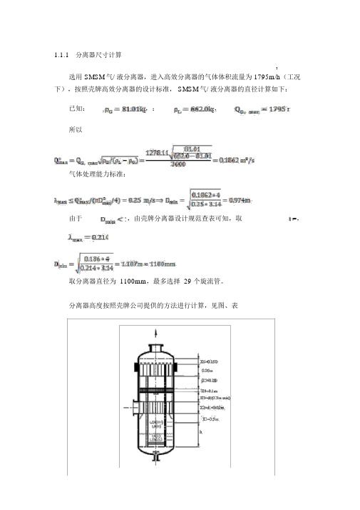
1.1.1分离器尺寸计算3选用 SMSM气/ 液分离器,进入高效分离器的气体体积流量为 1795m/h(工况下),按照壳牌高效分离器的设计标准, SMSM气/ 液分离器的直径计算如下:已知:,:,所以气体处理能力标准:由于,由壳牌分离器设计规范查表可知,取=,取分离器直径为 1100mm,最多选择 29 个旋流管。
分离器高度按照壳牌公司提供的方法进行计算,见图、表表分离器直径及涡流管个数的确定表D,m涡流管个数Q m*ax,m3 /s1459121621242932374452表高效分离器高度计算表项目高度, m项目X X 15X2X6X D 3X4h m ax,m/s 高度, m综上所述, DY气田干气脱汞方案闪蒸气处理工艺中,选用壳牌SMSM高效分离器,分离器的直径为1200mm,高度为 3200mm。
1.2 MEG再生塔 C-2201(1) 和凝析油稳定塔C-2301分别对 MEG再生塔和凝析油稳定塔进行选型并对塔径和高度进行计算。
1.2.1MEG再生塔和凝析油稳定塔基础数据MEG再生塔和凝析油稳定塔均选用整装填料塔,填料采用金属板波纹填料250Y 型,该种填料具有生产能力大,分离效率高,压力降小,操作弹性大,持液量小等优点。
250Y型填料主要性能参数见表。
表 250Y型填料主要性能参数表项目填料主要性能参数比表面积 a,m2/m3250空隙率ε, %973-1填料因子 a/ ε,m每米理论塔板数,个2~332液体负荷, m/(m? h)压力降, MPa/m3×10-4MEG再生塔中第二、六塔板气相负荷较大,作为MEG再生塔填料段塔径计算的基础数据,见表所示。
表 MEG再生塔塔径计算基础数据项目第二板第六板压力, KPa122温度,℃3气相体积流量 m/h气相流量 ,kg/h气相密度 kg/m3气相粘度, cp×10-3× 10⁻³液相流量 ,kg/h3494液相密度 ,kg/m 3液相粘度, cP稳定塔只有提馏段,第八塔板汽相负荷较大,作为脱丙丁烷塔的基础数据,如表所示。
技术规格书-换热器芯子
规格 80 Dn1400 Dn1500 Dn1364 Dn1480 Φ25x2
数量 104 208
正火 正火
备注
正火
退火 退火
材质 35CrMoA 30CrMoA
材料 16MnR 16MnII 20 Q235-A
16MnR J507 J507 J427 J427
Ⅴ 管口表
16MnII
20
J507
J427
J427
J427
符号 N1.N5 N3.N7 N2.N6 N4.N8 N9.N11 N10.N12
公称规格 350 350 350 350 G3/4" G3/4"
825
BES1400-2.0/2.5-825-9/25-4
16MnR 16MnII 20
容器类别
物料名称
物料特性
重空
重
量 其中不锈钢
充水重
kg 操
作
法规
设计标准
壳程 管程 二E
原油 原油 49102 79102
GB151-1999
Ⅱ 设计数据
腐蚀裕度 mm 焊接连 A 类 头系数 B 类 程数 管子与管板连接型式
JB/T4709-2000
产品焊接试板 JB4744-2000
A.B 类焊接接头每条应进行 20%射线检测,且不小于 250mm,相交接头必须检测
JB4730-94,Ⅲ级
A.B 类焊接接头每条应进行 20%射线检测,且不小于 250mm,相交接头必须检测
JB4730-94,Ⅲ级
管箱消除应力
表面处理
见侧视图
技术规格书
油气处理分公司(章): 东昊设备管理部(章)
技术特性表
Ⅰ 基本数据
分离器制造工艺设计
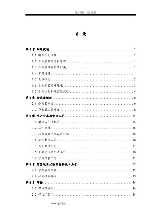
目录第1章制造概述 (1)1.1 制造工艺流程 (1)1.2 压力容器的选材原理 (1)1.3 压力容器材料的种类 (1)1.4 常用材料 (1)1.5 无损探伤 (2)1.6 压力容器的热处理 (3)1.7 压力试验和气密性试验 (4)第2章分离器概述 (6)2.1 分离器分类 (6)2.2 分离器工作原理 (6)第3章生产分离器制造工艺 (14)3.1 制造工艺流程图 (14)3.2 总体要求 (15)3.3 压力容器主要设计数据 (15)3.4 筒体制造工艺 (16)3.5 封头制造工艺 (17)3.6 主要受压件制造工艺 (18)3.7 容器组装工艺 (21)第4章容器液压试验及材料技术要求 (22)4.1 容器液压试验 (22)4.2 材料技术要求 (23)第5章焊接 (24)5.1 焊缝节点图 (24)5.2 焊接工艺卡 (24)实习心得 (31)参考文献 (32)第1章制造概述1.1 制造工艺流程工艺流程:下料——成型——焊接——无损检测——组对、焊接——无损检测——热处理——耐压实验1.2 压力容器的选材原理1.具有足够的强度,塑性,韧性和稳定性。
2.具有良好的冷热加工性和焊接性能。
3.在有腐蚀性介质的设备必须有良好的耐蚀性和抗氢性。
4.在高温状态使用的设备要有良好的热稳定性。
5.在低温状态下使用的设备要考虑有良好的韧性。
1.3 压力容器材料的种类1.碳钢,低合金钢2.不锈钢3.特殊材料:①复合材料(16MnR+316L)②刚镍合金③超级双向不锈钢④哈氏合金(NiMo:78% 20%合金)1.4 常用材料常用复合材料:16MnR+0Gr18Ni9A:按形状分:钢板、棒料、管状、铸件、锻件B:按成分分:碳素钢:20号钢 20R Q235低合金钢:16MnR、16MnDR、09MnNiDR、15CrMoR、16Mn锻件、20MnMo锻件高合金钢:0Cr13、0Cr18Ni9、0Cr18Ni10Ti尿素级材料:X2CrNiMo18.143mol(尿素合成塔中使用,有较高耐腐蚀性)焊接(一)焊前准备与焊接环境1、焊条、焊剂及其他焊接材料的贮存库应保持干燥,相对湿度不得大于60%。
- 1、下载文档前请自行甄别文档内容的完整性,平台不提供额外的编辑、内容补充、找答案等附加服务。
- 2、"仅部分预览"的文档,不可在线预览部分如存在完整性等问题,可反馈申请退款(可完整预览的文档不适用该条件!)。
- 3、如文档侵犯您的权益,请联系客服反馈,我们会尽快为您处理(人工客服工作时间:9:00-18:30)。
(11)HG/T 20592~20635-2009《钢制管法兰、垫片、紧固件》 2.2 优先顺序 应遵照下列优先次序执行: 本技术规格书 相关的规范和标准 若本规格书与有关的其它规格书、数据表、图纸以及上述规范和标准出现相互矛盾时, 应按最为严格的执行。 供货商若有与以上文件不一致的地方,应在其投标书中予以说明,若没有说明,则被认 为完全符合上述文件所有要求。 即使供货商符合本规格书的所有条款, 也并不等于解除供货 商对所有提供的设备和附件应当承担的全部责任,所提供的设备和附件应当具有正确的设 计,并且满足特定的设计和使用条件或当地有关的健康和安全法规。
中石化 中原石油工程 设计有限公司
项目号: SPEZY-DD17S446
技术规格书
文件号:SPE-0000 制 01-01 0版 第 5页 共 10 页
力为 4~5级; 秋季吹北风、 偏东风, 最大风力为 5~6 级;冬季多吹西北风,最大风力为 5~6级 5.3 水文资料 德新镇没有大的河流,但地下水较丰富。 5.4 地形地貌 德新镇大部分地区为古绵远河的冲积平原,仅东部有少许浅丘。地势东北高,西南低, 平均海拔高度 525m。 5.5 工程地质条件 设计基本风压值 地震设防烈度 场地土类别 地面粗糙度 5.6 设计参数 重烃分离器 (0506-V2) : 操作温度/设计温度:-60℃/-65℃, 操作压力/设计压力:5.0MPa/5.4MPa。 6. 技术要求 6.1 设计要求 6.1.1 重烃分离器应在设计温度和设计压力下满足规定的强度要求。工艺参数和设计数 据要求详见重烃分离器(0506-V2)数据表。 以下情况也要考虑: -试运行 -正常操作 -排污和放空 -总体安全 6.1.2 重烃分离器的丝网除沫器采用下装式,选用 H=150mm 的丝网除沫器。 6.1.3 重烃分离器的设计必须考虑到设备能在给定的环境条件长期安全运行,其使用寿 命应大于 15 年。 6.2 材料要求 6.2.1 重烃分离器所有选用的材料应符合相应的标准规范且满足本技术规格书的要求。 300Pa 7度(第二组 II B类 0.1g)
C
会签专业
签署Biblioteka 日期德阳 LNG 工厂装置整改项目 施工图设计
日期
技术规格书
项目号:SPEZY-DD17S446
签署
机制专业
会签专业
签署 监理批准
日期
签署 业主批准
日期
0 版 次
2018.05.10 日期 中石化 中原石油工程 设计有限公司 说明
成洁 设计 设计文件
倪平平 校对
张仲元 赵国勇 审核 审定 买方
批准
德阳 LNG 工厂装置整改项目 重烃分离器
四川中京燃气有限公司 设计文件编号 SPE-0000 制 01-01
工程设计证书:A141008990 工程勘察证书:B141008990
中石化 中原石油工程 设计有限公司 设计证书编号:A141008990 勘察证书编号:B141008990
项目号:SPEZY-DD17S446
技术规格书
文件号:SPE-0000 制 01-01 专业:机制
德阳 LNG 工厂装置整改项目 重烃分离器
阶段: 施工图设计 日期:2018.05.10 第 1页 共 10 页 0版
目
录
1. 前言 .......................................................................................................................................... 2 2. 相关资料 ................................................................................................................................. 2 3. 供货商要求 ............................................................................................................................. 3 4. 供货范围 ................................................................................................................................. 3 5. 设计基础数据 ......................................................................................................................... 4 6. 技术要求 ................................................................................................................................. 5 7. 标识 ......................................................................................................................................... 6 8. 检测和试验 ............................................................................................................................. 7 9. 涂层、包装、运输 ................................................................................................................. 8 10. 备品、备件及专用工具 ....................................................................................................... 8 11. 供货商文件要求 ................................................................................................................... 9 12. 服务与保证 ......................................................................................................................... 10
中石化 中原石油工程 设计有限公司 (8) 相关文件。 4.3 交接界限 4.3.1 管道系统
项目号: SPEZY-DD17S446
技术规格书
文件号:SPE-0000 制 01-01 0版 第 4页 共 10 页
所有与重烃分离器连接的工艺管道接口均应采用法兰连接,供货商应提供配对法兰(包 括垫片、螺栓和螺母) 。 4.3.2 基础 供货商应提供重烃分离器裙座底板尺寸及地脚螺栓孔布置图。 5. 设计基础数据 5.l 项目概况
中石化 中原石油工程 设计有限公司
项目号: SPEZY-DD17S446
技术规格书
文件号:SPE-0000 制 01-01 0版 第 3页 共 10 页
对于不能妥善解决的问题,供货商有责任以书面形式通知业主。 3. 供货商要求 3.1 供货商应通过 ISO9000 质量体系认证,有健全的质量保证体系。ISO9000 质量证书 必须在有效期内。 3.2 供货商应具有与压力和类别相匹配的压力容器设计和制造资格,并具有至少三年以 上同类压力容器的制造经验。同时具有符合国家压力容器安全监察机构有关法规的要求。 3.3 供货商应能提供良好的售后服务和技术支持。供货商应有在近年来相关领域中的供 货业绩,设计、制造能力证明及提供长期技术支持的能力。供货商需递交同类压力容器的实 际应用证明。 3.4 供货商可根据经验、技术和产品,推荐和提供与本技术规格书不同的方案。这些方 案应用中文加以详细和完整的描述,以供业主和设计方评估和决策。 3.5 供货商推荐的产品应该是成熟的产品类型,技术先进,经过证明,在要求的操作条 件下能够稳定、可靠地工作。 3.6 除非经业主批准,重烃分离器应完全依照本规格书、数据表及其它相关资料及规范 标准的要求。 规格书中的任何遗漏都不能作为解脱供货商责任的依据, 所有改动应提交给业 主批准。 4. 供货范围 4.1 概述 供货商应对重烃分离器的设计、材料采购、制造、零部件的组装、图纸、资料的提供以 及与各个分包商间的联络、协同、检验和试验负有全部责任。供货商还应对设备的性能、安 装、调试及售后服务负责。 4.2 供货范围 每台重烃分离器的供货范围应包括但不限于以下部分: (1) 重烃分离器本体,包括:壳体、裙座、吊耳、与外部连接的接管与法兰; (2) 直爬梯和顶部操作平台; (3) 铭牌; (4) 防腐、保冷支持圈、保冷材料及外壳; (5) 试车和开车用备品备件及专用工具; (6) 设备运输及现场指导安装; (7) 服务(设备调试及技术培训) ;
四川中京燃气有限公司 LNG 工厂位于四川省德阳市旌阳区德新镇新玉村二组。 工厂以附近新场气田 134 集气站的天然气作为原料,原料气经进站分离、计量稳压后, 进入天然气增压单元,经原料气压缩机增压至 5.2MPa(g)后进入净化系统。净化系统包括 天然气脱碳单元、 天然气脱水脱苯单元、 天然气脱汞单元、 天然气脱烃单元。 天然气经过 MDEA 脱二氧化碳、分子筛脱水、脱苯,活性炭脱汞装置的净化处理,使天然气满足液化指标后进 入液化系统。经过冷箱的过冷生产出合格的 LNG 产品在 LNG 储罐中储存,再通过 LNG 装车 鹤管进行装车,利用 LNG 槽车运至用户。 5.2 气象资料 本工程所在地德阳市德新镇,气象条件见表5.1: 气象要素 环境温度最低 环境温度最高 平均气温 年平均相对湿度 年平均日照数 无霜期 初霜期最早在 终霜期在 常年一般风力 1980年7月最大风力达到 6~7级。 春季多吹偏北 风,最大风力为 4~5级;夏季多吹东南风,最大风 h d 单位 ℃ ℃ ℃ 数量 -6.7 36.5 17.74 82.06% 1072 348 11月 4月15日前后 2~3级
