杰美康2dm860说明书
安捷伦SURE 2 Supercompetent Cells产品说明书
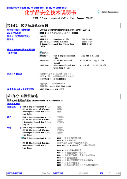
SURE 2 Supercompetent Cells, Part Number 200152*************(24小时)化学品安全技术说明书GHS product identifier 应急咨询电话(带值班时间)::供应商/ 制造商:安捷伦科技贸易(上海)有限公司中国(上海)外高桥自由贸易试验区英伦路412号(邮编:200131)电话号码: 800-820-3278传真号码: 0086 (21) 5048 2818SURE 2 Supercompetent Cells, Part Number 200152化学品的推荐用途和限制用途SURE 2 Supercompetent Cells 200152-41pUC 18 DNA Control Plasmid 200231-422-Mercaptoethanol For Ultra Comp Cells210210-43部件号:部件号(化学品试剂盒):200152安全技术说明书根据 GB/ T 16483-2008 和 GB/ T 17519-2013GHS化学品标识:推荐用途SURE 2 Supercompetent Cells1 ml (10 x 0.1 ml)200231-42pUC 18 DNA Control Plasmid0.01 ml (0.1 ng / µl)210210-432-Mercaptoethanol For Ultra Comp Cells0.025 ml (1.22 M 25 µl):物质或混合物的分类根据 GB13690-2009 和 GB30000-2013紧急情况概述SURE 2 Supercompetent Cells 液体。
pUC 18 DNA Control Plasmid 液体。
2-Mercaptoethanol For Ultra Comp Cells 液体。
SURE 2 Supercompetent Cells 无资料。
杰美康2DM542数字步进驱动器 用户手册说明书
2DM542数字步进驱动器用户手册地址:深圳市宝安区留仙三路鸿威工业区A栋2楼电话:*************26502268传真:*************E-mail:*******************Http: //本手册的所有内容,著作财产权归深圳市杰美康机电有限公司所有,未经深圳市杰美康机电有限公司许可,任何单位或个人不得随意仿制、拷贝、撰抄。
本手册无任何形式的担保、立场表达或其它暗示。
如有本手册所提到的产品的信息,所引起的直接或间接的资料流出,导致利益损失后果,深圳市杰美康机电有限公司与所属员工不承担任何责任。
除此以外,本手册提到的产品及其资料仅供参考,内容如有更新,恕不另行通知。
版权所有,不得翻印。
深圳市杰美康机电有限公司目录目录 (2)一、概述 (3)二、特点 (3)三、端口说明 (4)3.1控制信号输入端口 (4)3.2功率端口 (4)四、技术指标 (6)五、控制信号接线 (7)5.1 控制信号单端共阳极接线 (7)5.2 控制信号单端共阴极接线 (8)5.3 控制信号差分接线方式 (9)5.4 232串口通信接线图 (10)5.5 控制信号时序图 (10)六、拨码开关设定 (11)6.1 SW-2拨码开关说明 (11)6.1.1电流拨码设置 (12)6.1.2停止电流设定 (12)6.1.3细分拨码设置 (13)6.2 SW-1侧拨码开关说明 (14)七、错误报警及LED灯闪烁次数 (15)八、安装尺寸 (16)九、接线图 (17)十、参数设置 (18)十一、常见问题及故障处理 (21)11.1 电源灯不亮 (21)11.2上电亮红灯报警 (21)11.3 脉冲输入后不转动 (21)一、概述2DM542是数字式两相步进驱动,采用最新的32位ARM 处理器进行控制。
此数字驱动器外设细分、电流、辅助功能拨码,用户可根据需要自由设置,内部编写先进驱动控制算法,能保证步进电机在各速度段精准、稳定运行,其中,内置细分算法,能使电机在低转速时平稳运行;中高速力矩补偿算法,能最大限度的提高电机中高转速时的转矩;参数自整定算法,能自适应各种电机,最大限度发挥电机性能;内置平滑算法,能极大提升电机加减速性能。
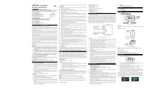
Contec CMS50D2 脉搏氧气饱和度计器用户手册说明书
CMS50D2User ManualP u l s e O x i m e t e rContec Medical Systems Co., Ltd.Address:No.112 Qinhuang West Street, Economic &Technical Development Zone, Qinhuangdao, Hebei Province, PEOPLE’S REPUBLIC OF CHINA Tel: +86-335-8015430Fax: +86-335-8015588Technical support:+86-335-8015431E-mail:*****************.cnWebsite: EC REPRESENTATIVEShanghai International Holding Corp. GmbH(Europe)Address: Eiffestrasse 80, 20537, Hamburg, GermanyTel: +49-40-2513175Fax: +49-40-255726E-mail:*********************CMS2.782.294(CE)ESS/1.0 1.4.01.01.601 2019.11Instructions to UserDear Users, thank you very much for purchasing our product.This Manual is written and compiled in accordance with the council directive MDD93/42/EEC for medical devices and harmonized standards. In case of modifications and software upgrades, the information contained in this document is subject to change without notice.The Manual describes, in accordance with the Pulse Oximeter's features and requirements, main structure, functions, specifications, correct methods for transportation, installation, usage, operation, repair, maintenance and storage, etc. as well as the safety procedures to protect both the user and equipment. Refer to the respective chapters for details.Please read the Manual very carefully before using this equipment. These instructions describe the operating procedures to be followed strictly, failure to follow these instructions can cause measuring abnormality, equipment damage and personal injury. The manufacturer is NOT responsible for the safety, reliability and performance issues and any monitoring abnormality, personal injury and equipment damage due to user's negligence of the operation instructions. The manufacturer’s warranty service does not cover such faults.Owing to the forthcoming renovation, the specific products you received may not be totally in accordance with the description of this User Manual. We would sincerely regret for that.This product is medical device, and can be used repeatedly. Its using life is 3 years. WARNING:The uncomfortable or painful feeling may appear if using the device ceaselessly, especially for the microcirculation barrier patients. It is recommended that the sensor should not be applied to the same finger for over 2 hours.For the individual patients, there should be a more prudent inspecting in the placing process. The device can not be clipped on the edema and tender tissue.The light (the infrared is invisible) emitted from the device is harmful to the eyes, so the user and the maintenance man, can not stare at the light.Testee can not use enamel or other makeup.Testee’s fingernail can not be too long.Please peruse the relative content about the clinical restrictions and caution.This device is not intended for treatment.Caution: Federal law restricts this device to sale by or on the order of a physician.1 Safety1.1 Instructions for Safe OperationsCheck the main unit and all accessories periodically to make sure that there is no visible damage that may affect patient's safety and monitoring performance about cables and transducers. It is recommended that the device should be inspected once a week at least. When there is obvious damage, stop using the monitor.Necessary maintenance must be performed by qualified service engineers ONLY.Users are not permitted to maintain it by themselves.The oximeter cannot be used together with devices not specified in User's Manual.Only the accessory that appointed or recommendatory by manufacture can be used with this device.This product is calibrated before leaving factory.1.2 WarningsExplosive hazard—DO NOT use the oximeter in environment with inflammable gas such as some ignitable anesthetic agents.DO NOT use the oximeter while the testee measured by MRI and CT.The person who is allergic to rubber can not use this device.The disposal of scrap instrument and its accessories and packings(including battery, plastic bags, foams and paper boxes) should follow the local laws and regulations.Please check the packing before use to make sure the device and accessories are totally in accordance with the packing list, or else the device may have the possibility of working abnormally. Please don't measure this device with function test paper for the device's relatedinformation.1.3 AttentionsKeep the oximeter away from dust, vibration, corrosive substances, explosive materials,high temperature and moisture.If the oximeter gets wet, please stop operating it.When it is carried from cold environment to warm or humid environment, please do notuse it immediately.DO NOT operate keys on front panel with sharp materials.High temperature or high pressure steam disinfection of the oximeter is not permitted.Refer to User Manual in the relative chapter for instructions of cleaning anddisinfection.Do not have the oximeter immerged in liquid. When it needs cleaning, please wipe itssurface with medical alcohol by soft material. Do not spray any liquid on the devicedirectly.When cleaning the device with water, the temperature should be lower than 60 ℃.As to the fingers which are too thin or too cold, it would probably affect the normalmeasure of the patients' SpO and pulse rate, please clip the thick finger such as thumband middle finger deeply enough into the probe.Do not use the device on infant or neonatal patients.The product is suitable for children above four years old and adults (Weight should bebetween 15 kg to 110 kg).The device may not work for all patients. If you are unable to achieve stable readings,discontinue use.The update period of data is less than 5 seconds, which is changeable according todifferent individual pulse rate.The waveform is normalized.Please read the measured value when the waveform onscreen is equably and steady-going, Here this measured value is optimal value. And thewaveform at the moment is the standard one.If some abnormal conditions appear on the screen during test process, pull out thefinger and reinsert to restore normal use.The device has normal useful life for three years since the first electrified use.The hanging rope attached the product is made from Non- allergy material, if particulargroup are sensitive to the hanging rope, stop using it. In addition, pay attention to theuse of the hanging rope , do not wear it around the neck avoiding cause harm to thepatient.The instrument dose not have low-voltage prompt function, it only shows thelow-voltage.please change the battery when the battery energy is used out.When the parameter is particularly, The instrument dose not have prompt function.Donot use the device in situations where prompts are required.Batteries must be removed if the device is going to be stored for more than one month,or else batteries may leak.A flexible circuit connects the two parts of the device. Do not twist or pull on theconnection.1.4 Indication for UseThe Fingertip Pulse Oximeter is a non-invasive device intended for the spot-check of oxygensaturation of arterial hemoglobin (SpO) and the pulse rate of adult and pediatric patients inhome and hospital environments (including clinical use in internist/surgery, anesthesia,intensive care ect.). This device is not intended for continuous monitoring.2 OverviewThe pulse oxygen saturation is the percentage of HbO in the total Hb in the blood, so-calledthe O concentration in the blood. It is an important bio-parameter for the respiration. For thepurpose of measuring the SpO more easily and accurately, our company developed the PulseOximeter. At the same time, the device can measure the pulse rate simultaneously.The Pulse Oximeter features in small volume, low power consumption, convenient operationand being portable. It is only necessary for patient to put one of his fingers into a fingertipphotoelectric sensor for diagnosis, and a display screen will directly show measured value ofHemoglobin Saturation.2.1 ClassificationClass II b, (MDD93/42/EEC IX Rule 10)2.2 FeaturesOperation of the product is simple and convenient.The product is small in volume, light in weight (total weight is about 50g includingbatteries) and convenient in carrying.Power consumption of the product is low and the two originally equipped AAAbatteries can be operated continuously for 20 hours.The product will enter standby mode when no signal is in the product within 5seconds.Display direction can be changed,easy to view.2.3 Major Applications and Scope of ApplicationThe Pulse Oximeter can be used to measure human Hemoglobin Saturation and pulse ratethrough finger, and indicate the pulse intensity by the bar-display. The product is suitable foruse in family, hospital (Ordinary sickroom), Oxygen Bar, social medical organizations andalso the measure of saturation oxygen and pulse rate.The product is not suitable for use in continuous supervision for patients.The problem of overrating would emerge when the patient is suffering fromtoxicosis which caused by carbon monoxide, the device is not recommended to be usedunder this circumstance.2.4 Environment RequirementsStorage Environmenta) Temperature: -40 ℃ ~ +60 ℃b) Relative humidity: ≤95%c) Atmospheric pressure: 500 hPa ~ 1060 hPaOperating Environmenta) Temperature: 10 ℃ ~ 40 ℃b) Relative Humidity: ≤75%c) Atmospheric pressure: 700 hPa ~ 1060 hPa3.1 Principle of MeasurementPrinciple of the Oximeter is as follows: An experience formula of data process is establishedtaking use of Lambert Beer Law according to Spectrum Absorption Characteristics ofReductive Hemoglobin (Hb) and Oxyhemoglobin (HbO) in glow & near-infrared zones.Operation principle of the instrument is: Photoelectric Oxyhemoglobin InspectionTechnology is adopted in accordance with Capacity Pulse Scanning & Recording Technology,so that two beams of different wavelength of lights can be focused onto human nail tipthrough perspective clamp finger-type sensor. Then measured signal can be obtainedby aphotosensitive element, information acquired through which will be shown on screen throughtreatment in electronic circuits and microprocessor.Figure 1 Operating principle3.2 Caution1.The finger should be placed properly (see the attached illustration of this manual,Figure 5), or else it may cause inaccurate measurement.2.The SpO sensor and photoelectric receiving tube should be arranged in a way with thesubject’s arteriole in a position there between.3.The SpO sensor should not be used at a location or limb tied with arterial canal orblood pressure cuff or receiving intravenous injection.4.Make sure the optical path is free from any optical obstacles like rubberized fabric.5.Excessive ambient light may affect the measuring result. It includes fluorescent lamp,dual ruby light, infrared heater, direct sunlight and etc.6.Strenuous action of the subject or extreme electrosurgical interference may also affectthe accuracy.7.Testee can not use enamel or other makeup.3.3 Clinical Restrictions1.As the measure is taken on the basis of arteriole pulse, substantial pulsating blood flowof subject is required. For a subject with weak pulse due to shock, low ambient/bodytemperature, major bleeding, or use of vascular contracting drug, the SpO waveform(PLETH) will decrease. In this case, the measurement will be more sensitive tointerference.2.For those with a substantial amount of staining dilution drug (such as methylene blue,indigo green and acid indigo blue), or carbon monoxide hemoglobin (COHb), ormethionine (Me+Hb) or thiosalicylic hemoglobin, and some with icterus problem, theSpO determination by this monitor may be inaccurate.3.The drugs like dopamine, procaine, prilocaine, lidocaine and butacaine may also be amajor factor blamed for serious error of SpO measure.4.As the SpO value serves as a reference value for judgement of anemic anoxia and toxicanoxia, some patients with serious anemia may also report good SpO measurement.1)Display Format: LCD Display;SpO Measuring Range: 0% ~ 100%;Pulse Rate Measuring Range: 30 bpm ~ 250 bpm;Pulse Wave Display: columniation display and the waveform display.PI Measuring Range: 0 ~ 20%2)Power Requirements: 2×1.5 V AAA alkaline battery (or using the rechargeable batteryinstead),adaptable range: 2.6 V - 3.6 V.3)Power Consumption: Smaller than 80 mA.4)Resolution: 1% for SpO, 1 bpm for Pulse Rate and 0.1% for PI.5)Measurement Accuracy: ±2% in stage of 70% ~ 100% SpO, and meaningless whenstage being smaller than 70%. ±2 bpm during the pulse rate range of 30 bpm ~ 99 bpmand ±2% during the pulse rate range of 100 bpm ~ 250 bpm .6)Measurement Performance in Weak Filling Condition: SpO and pulse rate can beshown correctly when pulse-filling ratio is 0.4%. SpO error is ±4%, pulse rate error is± 2 bpm during the pulse rate range of 30 bpm ~ 99 bpm and ±2% during the pulse raterange of 100 bpm ~ 250 bpm .7)Resistance to surrounding light:The deviation between the value measured in thecondition of man-made light or indoor natural light and that of darkroom is less than±1%.8)It is equipped with a function switch: The product will enter standby mode when nosignal is in the product within 5 seconds.9)Optical SensorRed light (wavelength is 660 nm, 6.65 mW)Infrared (wavelength is 880 nm, 6.75 mW)One hanging ropeTwo batteries(optional)One User Manual6 Installation6.1 View of the Front PanelFigure 3 Batteries installationPlease take care when you insert the batteries for the improper insertionmay damage the device.6.3 Mounting the Hanging RopeStep 1. Put the end of the rope through the hole refer to Figure 3 .Step 2. Put another end of the rope through the first one and then tighten it.7 Operating Guide1)Insert the two batteries properly to the direction, and then replace the cover.2)Open the clip as shown in Figure 5.Figure 5 Put finger in position3)Let the patient’s finger put into the rubber cushions of the clip (make sure thefinger is in the right position), and then clip the finger.4)Press the button once on front panel.5)Do not shake the fingerand keep the patient at ease duringthe process.Meanwhile, human body is not recommended in movement status.6)Get the information directly from screen display.When the device is in operation status, the display mode can be changed.7)When the device is in standby mode, pressing the button can exit it; When the device is in operation status, pressing the button can enter into menus; In the state of prompt, press the button long can pause prompt for 60s.Press the button when the device is in operation status, can enter into menus(in the Figure6,Figure7,Figure 8 ,Figure 9, press the button shortly can move the drop-down icon, press the button long can turn on/off the pulse sound prompt, enter the next menu to change the up and down limit of pulse rate and SpO, and select the direction of the up and down limit.)Figure 6 Menu interface Figure 7 prompt setting interfaceFigure 8 PR prompt limits setting interface Figure 9 SpO prompt limits setting interfaceFingernails and the luminescent tube should be on the same side.Please change the batteries when the low-voltage displayed on the screen. Please clean the surface of the device before using. Wipe the device withmedical alcohol first, and then let it dry in air or clean it by dry clean fabric. Using the medical alcohol to disinfect the product after use, prevent fromcross infectio n for next time use.Please take out the batteries if the oximeter is not in use for a long time.The best storage environment of the device is -40 ºC to 60 ºC ambienttemperature and not higher than 95% relative humidity.Users are advised to calibrate the device termly (or according to thecalibrating program of hospital). It also can be performed at the state-appointed agent or just contact us for calibration. High-pressure sterilization cannot be used on the device. Do not immerse the device in liquid.It is recommended that the device should be kept in a dry environment.Humidity may reduce the useful life of the device, or even damage it.Trouble Possible ReasonSolutionThe SpOand Pulse Rate can not be displayed normally 1. The finger is not properly positioned.2. The patient’s SpO is too low to be detected. 1. Place the finger properly and try again.2. Try again; Go to a hospital for a diagnosis if you are sure the device works allright.The SpO and Pulse Rate are not displayed stably1. The finger is not placed inside deep enough.2. The finger is shaking or the patient is moving. 1. Place the finger properly and try again.2. Let the patient keep calm The device can not be turned on1. The batteries are drained or almost drained.2. The batteries are not inserted properly.3. The malfunction of the device.1. Change batteries.2. Reinstall batteries.3. Please contact the local service center.The display is off suddenly 1. The product will enter standby mode when no signal is in the product within 5 seconds2. The batteries are almost drained.1. Normal.2. Change batteries.SymbolDescriptionType BFRefer to instruction manual/bookletThe battery voltage indication is deficient (change the battery in time avoiding the inexact measure)1.No finger inserted2.An indicator of signal inadequacyBattery positive electrodeBattery cathode1.Exit standby mode.2.Can enter into menus. SNSerial numberPrompt inhibitWEEE (2002/96/EC)IP22International ProtectionThis item is compliant with Medical Device Directive 93/42/EEC of June 14, 1993, a directive of the European Economic Community.Manufacture DateStorage and Transport Temperature limitationStorage and Transport Humidity limitationStorage and Transport Atmospheric pressure limitationThis side upFragile, handle with careKeep dryRecyclableDisplay InformationDisplay Mode The Pulse Oxygen Saturation (SpO ) LCD Pulse Rate (PR) LCD Perfusion Index (PI) LCD display Pulse Intensity (bar-graph) LCD bar-graph display Pulse waveLCDSpO Parameter Specification Measuring range 0% ~ 100%, (the resolution is 1%). Accuracy70% ~ 100%: ±2%, Below 70% unspecified. Optical SensorRed light (wavelength is 660 nm) Infrared (wavelength is 880 nm)Pulse Parameter Specification Measuring range 30 bpm ~ 250 bpm (the resolution is 1 bpm) Accuracy ±2 bpm or ±2% select largerPulse Intensity RangeContinuous bar-graph display, the higher display indicate the stronger pulse.Battery Requirement1.5 V (AAA size) alkaline batteries × 2 or rechargeable battery Battery Useful LifeTwo batteries can work continually for 20 hours Dimensions and Weight Dimensions 60(L) × 30.5(W) × 32.5(H) mm WeightAbout 50 g (with the batteries)Appendix1Guidance and manufacture’s declaration-electromagnetic emissionfor all EQUIPMENT and SYSTEMSGuidance and manufacture’s declaration –electromagnetic emission The CMS50D2 Pulse Oximeter is tended for use in the electromagnetic environment specified below. The customer of the user of the CMS50D2 Pulse Oximeter should assure that it isused in such an environment. Emission test Compliance Electromagnetic environment-guidance RF emissions CISPR 11 Group 1The CMS50D2 Pulse Oximeter uses RF energy only for their internal function. Therefore, its RF emissions are very low and are not likely to cause any interference in nearby electronic equipment.RF emissions CISPR 11Class B The CMS50D2 Pulse Oximeter is suitable for use in all establishments, including domestic establishments and those directly connected to the public low-voltage power supply network that supplies buildings used for domestic purposes.Harmonic emissionsIEC 61000-3-2 Not applicableV oltage fluctuations/ flicker emission IEC 61000-3-3Not applicableGuidance and manufacture’s declaration-electromagnetic immunityfor all EQUIPMENT and SYSTEMSGuidance and manufacture’s declaration-electromagnetic immunityThe CMS50D2 Pulse Oximeter is intended for use in the electromagnetic environment specified specified below. The the user of CMS50D2 Pulse Oximeter should assure that it is used in such an environment. Immunity testIEC60601 test levelCompliance levelElectromagneticenvironment -guidanceElectrostaticdischarge(ESD) IEC 61000-4-2±6KV contact ±8KV air ±6KV contact ±8KV air Floors should be wood, concrete or ceramic tile. Iffloor are covered withsynthetic material, the relative humidity should be at least 30%. Power frequency (50Hz)magnetic field IEC 61000-4-8 3A/m3A/mPower frequency magnetic fields should be at levels characteristic of a typical location in a typical commercial or hospital environmentGuidance and manufacture’s declaration-electromagnetic immunitytransmitters, as determined by an electromagnetic site survey, a should be less than the compliance level in each frequency range.bInterference may occur in the vicinity of equipment marked with the following symbol:NOTE 1 At 80MHz and 800MHz, the higher frequency range applies. NOTE 2 These guidelines may not apply in all situations. Electromagneticpropagation is affected by absorption and reflection from structures, objects and people.a. Field strengths from fixed transmitters, such as base stations for radio (cellular/cordless) telephones and land mobile radios, amateur radio, AM and FM radio broadcast and TV broadcastcannot be predicted theoretically with accuracy. To assess the electromagnetic environment due to fixed RF transmitters, an electromagnetic site survey should be considered. If the measured field strength in the location in which The CMS50D2 Pulse Oximeter is used exceeds the applicable RF compliance level above, the CMS50D2 Pulse Oximeter should be observed to verify normal operation. If abnormal performance is observed, additional measures may be necessary, such as reorienting or relocating the CMS50D2 Pulse Oximeter.b. Over the frequency range 150 KHz to 80 MHz, field strengths should be less than 3V/m.Recommended separation distances between portable and mobile RF communications equipment and the EQUIPMENT or SYSTEMAppendix 2StatePrompt condition delay Prompt signal generation delay Low voltage prompt 60s 5ms SpO prompt 1s 5ms Pulse rate prompt 1s 5ms Finger out prompt 16ms5ms。
DM860数字式两相步进驱动器使用说明书
深圳市雷赛智能控制股份有限公司地址:深圳市南山区登良路25号天安南油工业区二座三楼邮编:518052电话:400-885-5521传真:0755-********Email:info@网址:上海分公司北京办事处地址:上海市淞江区九亭镇九新公路地址:北京市朝阳区北苑路13号院领地76号嘉和阳光大厦9楼office1号楼A单元606号电话:021-********电话:010-********传真:021-********传真:010-********DM860数字式两相步进驱动器使用说明书版权所有不得翻印【使用前请仔细阅读本手册,以免损坏驱动器】深圳市雷赛智能控制股份有限公司目录一、产品简介 (2)1.概述 (2)2.特点 (2)3.应用领域 (2)二、电气、机械和环境指标 (2)1.电气指标 (2)2.使用环境及参数 (3)3.机械安装图 (3)4.加强散热方式 (4)三、驱动器接口和接线介绍 (4)1.接口描述 (4)2.控制信号接口电路 (5)3.控制信号时序图 (5)4.控制信号模式设置 (6)5.接线要求 (6)四、电流、细分拨码开关设定和参数自整定 (7)1.电流设定 (7)2.细分设定 (7)3.参数自整定功能 (8)五、供电电源选择 (8)六、电机选配 (8)1.电机选配 (8)1.电机接线 (9)2.输入电压和输出电流的选用 (9)七、典型接线案例 (10)八、保护功能 (11)九、常见问题 (12)1.应用中常见问题和处理方法 (12)2.用户常见问题解答 (13)雷赛产品保修条款 (14)DM860数字式两相步进驱动器一、产品简介1.概述DM860是雷赛公司新推出的数字式两相步进电机驱动器,采用最新32位DSP技术,用户可以设置400~51200内的细分以及额定电流内的任意电流值,能够满足大多数场合的应用需要。
由于采用内置微细分技术,即使在低细分的条件下,也能够达到高细分的效果,低中高速运行都很平稳,噪音超小。
杰尼奥科技的记录仪产品参考指南说明书

RD8900 £1305
S-19 Color Universal 1 to 18 0.2 sec and logs to 120 sec Ethernet, Flash mem CE, CSA
Vertical, Trend and Digital Print Recorders
Model Series
Universal
Universal
Universal
Channels
1 or 2
6 or 12
2, 4, 6 or 12
Sample Rate
0.01 sec to 10 min
100 m sec
0.25 sec to 10 min
Features
PCMCIA memory Ethernet, USB card, CE optional DAS Software
CTH100 £201 S-71
CT87V £202 S-72
Style
Circular
Circular
Inputs*
Temp, RH
Temperature
Channels Chart Size Chart Speed
2 6.5" 7 day/rev
1
6"WDPIRUG &7
&$1$'$ ZZZRPHJDFD /DYDO 4XHEHF 7&20(*$
81,7(' .,1*'20 ZZZ RPHJDFRXN 0DQFKHVWHU (QJODQG
)5$1&( ZZZRPHJDIU
CT8100 £710
S-57 Circular Universal
Ergotron CareFit Combo System 产品说明书

© 2022 Ergotron, Inc. All rights reservedC areFit Combo System• F lexible workfl ows: Easy screensharing and one-hand stowing enhances patient interactions • C omfortable documentation: Off ers ergonomic height-adjustment, optional worksurface and intuitive access to tools • N eat workspace: Concealed cablemanagement minimizes clutter and supports infection control • S upports uptime: Convenient cord access simplifi es maintenance with timely support available from our expert team • W arm aesthetic: Modular wall mountenhances new and existing healing spaces • Q uality construction: Sturdy design supports multiple confi gurations and installation optionsSupport genuine patient connections and help reduce the risk of errors with the modular CareFit Combo System that enables an e cient and comfortable documentation experience at the point of care. Easy screensharing, one-hand stowing and intuitive access to tools allow nurses to focus on patient care. The design enhances healing spaces with concealed cable management that promotes infection control, serviceability and uptime for IT teams.Y ADAPT TO CHANGING WORKFLOWSProvides nurses with renewed control over individual workflows and health to help facilitate efficient documentation and foster patient relationships.Hidden cable management and simple cord access makes it easy for IT teams to maintain or upgrade workstations so they can efficiently get the job done.MODULAR – FULL-MOTION – CUSTOMIZABLE1 P ersonalized, ergonomic monitor positioning for each user with 180° of pan and 5″ (13 cm) of independent adjustment2 F ull unit extends up to 65″ (165 cm) for documentation at a patient’s bedside or in a private space3 W all Track covers create a clean, streamlined look with hidden cabling4 S pace-saving design easily folds when not in use to open up more work area5 S upport neat, healing spaces with concealed cable management that enhances infection control6 E nable efficient, secure access with space for an RFID employee badge reader 123456SPACE-SAVING STORAGE5 S tows quickly and easily with just one handneeded to fl ip up the worksurface 6 L ocks in place for secure stowing upright in front of the monitorThoughtful ergonomics for comfortable caregivingINTUITIVE WORKFLOWS1 Extension helps minimize the distance and steps to the patient2 Full unit moves together with a light touch to give caregivers fl exibility and choice3 Supports caregiver-patient engagement with independent monitor adjustment 4Convenient scanner access with installation on either side34216STEP 2: CHOOSE YOUR CPU PLACEMENT TO BUILD YOUR WORKSTATION Wall-mounted CPUCPU under worksurface trayCareFit Combo System 45-618-251CareFit Combo System with Worksurface 45-619-251CareFit Combo Arm 45-621-251CareFit Combo Arm with Worksurface 45-622-251 Configure your wall system for your workflowSTEP 1: SELECT YOUR BASE UNITSTEP 3: ADD ACCESSORIES TO FITYOUR UNIQUE NEEDSCPU Wall Cabinet 98-543-251Clean design keeps CPU secure andextra cables and power brick out of view CareFit Combo Extender98-547-251Provides extra reach and fl exibility forlarger care applicationsCareFit Combo CPU Tray98-548-251Saves valuable wall space by installingunder the worksurfaceCareFit Combo WirelessScanner Bracket 98-549-251Supports effi cient workfl ows withinstallation on either sideCareFit Combo Scanner Bracket98-551-251Supports effi cient workfl ows withinstallation on either sidePrinter Bracket for Wall Track98-578-251Keeps printer in reach to maximize time with patients; installs on either side 34″ Wall Track 31-018-216Enables a sturdy installation; required for CareFit Combo Arm CareFit Wall Track 34″ Covers98-609-030Hides cabling for a neat look andsupports infection controlLarge worksurfaceCPU under worksurface tray:T otal height with CPU box is 44″ (111.8 cm)Determine the additional technology you will use in your confi gurationArea for suppliesTHE DESIGN ENHANCES HEALING SPACESWITH CONCEALED CABLE MANAGEMENT THAT PROMOTES INFECTION CONTROL, SERVICEABILITY AND UPTIME FOR IT TEAMS.44″ (111.8 c m )USING A CPUUSING AN AIOArea for SuppliesLarge WorksurfaceArea for SuppliesLarge WorksurfaceCPU Wall Cabinet ORCPU TrayWired Scanner BracketORWireless Scanner BracketUpORDownPrinter BracketWired Scanner BracketOR Wireless Scanner BracketPlace RFIDPrinter Bracket Place RFIDPopular configurations for patient-centereddocumentationCareFit Combo Arm with Scanner Bracketand Printer Bracket(designed for all-in-one workflows)CareFit Combo Arm with Extender,Wireless Scanner Bracket, and Printer Bracket(designed for all-in-one workflows)CareFit Combo System with Worksurface,Wall Cabinet and Wireless Scanner BracketCareFit Combo Arm with Worksurface,Wall Cabinet, Wireless Scanner Bracketand Printer BracketCareFit Combo Arm with Worksurface,Extender, CPU Tray and Scanner BracketCareFit Combo System with Worksurface,Extender, CPU Tray, Scanner Bracketand Printer BracketCareFitComboSystemCareFitComboSystemwithWorksurfaceFolds close to the wall when notin use to maximize space11″ (28 cm)10″ (25.5 cm)13″ (33 cm)12″ (31 cm)Combo ArmCombo Armwith Worksurface Combo SystemCombo Systemwith Worksurface45-621-25145-622-25145-618-25145-619-251Extender 98-547-251≤ 27″LCD SIZE IS APPROXIMATION. DIMENSION IS DIAGONAL MEASUREMENT OF SCREEN. LCD SIZE MAY BE EXCEEDED AS LONG AS SCREEN WEIGHT DOES NOT EXCEED MAXIMUM WEIGHT CAPACITY OF THE MOUNT.LCD: 8–22 lbs (3.6–10 kg)Worksuface: 1.5 lbs (0.68 kg)20″ (51 cm)LCD: 25° 20° / ↓5°Worksurface: 90°Download additional resources at .For more information:USA&Canada:800.888.8458/+1.651.681.7600/************************ EMEA:+31.33.45.45.600/********************APAC:********************************LATAMSales:Mexico/+1.800.681.1820/*********************** Custom:*******************© Ergotron, Inc. 07.14.2022Literature made in the U.S.A.Content subject to change.Ergotron devices are not intended to cure, treat, mitigate or prevent any disease. Patent information available at /patents.WorkFit, StyleView, LearnFit, Neo-Flex, PowerShuttle, LiFeKinnex, CareFitand eKinnex are trademarks of Ergotron.System with accessory extender (98-547-251) reaches57.5″ (146 cm)System with worksurface and accessory extender (98-547-251) reaches65″ (165.7 cm)。
CANalyst-II+用户手册说明书
广州致远电子股份有限公司CANalyst-II+用户手册CAN-bus 总线分析仪类别内容关键词CANalyst-II+ 分析仪 摘要CANalyst-II+产品描述与使用指导修订历史版本日期原因V1.00 2015/06/26 创建文档目录1. 功能简介 (1)1.1产品概述 (1)1.2功能特点 (1)1.3典型应用 (2)2. 设备安装 (3)2.1供电模式 (3)2.1.1外部电源供电模式 (3)2.1.2USB总线供电模式 (3)2.2CAN-bus连接器 (3)2.3信号指示灯 (3)2.4系统连接 (4)2.4.1CAN总线连接 (4)2.4.2总线终端电阻 (5)2.4.3USB总线连接 (5)3. 软件安装及使用 (6)3.1系统要求 (6)3.2软件安装 (6)3.3初次使用指南 (6)4. 常见问题 (12)5. 检查和维护 (15)6. 附录:CAN2.0B协议帧格式 (16)7. 免责声明 (18)1. 功能简介1.1 产品概述CANalyst-II+高性能CAN接口卡是与USB2.0总线全速规范兼容的,集成1~2路CAN 接口的高性能型CAN-bus总线通讯接口卡。
采用CANalyst-II+高性能CAN接口卡,PC可以通过USB总线连接至CAN-bus网络,构成现场总线实验室、工业控制、高性能小区、汽车电子网络等CAN-bus网络领域中数据处理、数据采集的CAN-bus网络控制节点。
CANalyst-II+高性能CAN接口卡是CAN-bus产品开发、CAN-bus数据分析的强大工具;同时,具有体积小巧、即插即用等特点,也是便携式系统用户的最佳选择。
CANalyst-II+接口卡上自带电气隔离模块,使接口卡避免由于地环流的损坏,增强系统在恶劣环境中使用的可靠性。
CANalyst-II+高性能CAN接口卡支持Win2000/XP等操作系统,也支持Linux2.6版版本的操作系统。
Koden MDC 2200 2500系列多功能显示器操作手册说明书
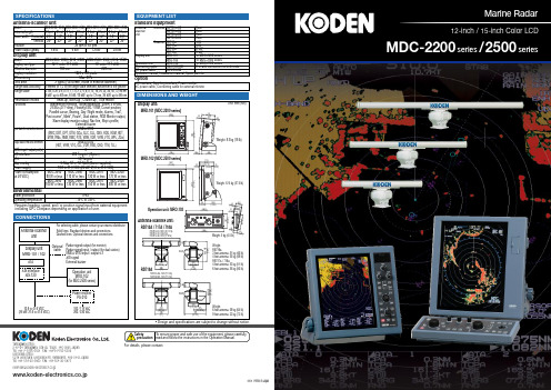
09.01 Printed in JapanSafetyprecaution T o ensure proper and safe use of the equipment, please carefully read and follow the instructions in the Operation Manual.Tamagawa Office:2-13-24 Tamagawa, Ota-ku, Tokyo, 146-0095 Japan Tel: +81-3-3756-6501 Fax: +81-3-3756-6509Uenohara Office:5278 Uenohara, Uenohara-shi, Yamanashi, 409-0112 Japan Tel: +81-554-20-5860 Fax: +81-554-20-5875• Design and specifications are subject to change without notice.For details, please contact:www.koden-electronics.co.jp*****************************.jpMDC-2200 series / 2500 series12-inch / 15-inch Color LCDTrue trail functionThe display shows exact movement of other vessels like drawing tails, while land and buoys are shown as station-ary objects even while your vessel is moving.This makes it easy for you to distinguish moving from stationary objects.ATA with up to 50 targets as standardThe convenient ATA (Automatic Tracking Aid) function comes as standard.The latest movements of other vessels can be shown instantaneously in vector form and numeric form, ensur-ing safe navigation.If the automatic acquisition zone is set, the targets up to 50 entering the zone will be locked automatically.Map Overlay with C-Map chart (NT+ or NT MAX)C-Map chart NT+ or NT MAX (owner supplied) is overlaid on the radar screen to provide clear radar pictures of coastlines, buoys, and other fea-tures.**Even in Head-up mode, the chart fol-lows smoothly in accordance with change of the heading of vessel.Furthermore, waypoints, buoys, and hazardous targets can be overlaid for safer navigation.C-Map NT MAX “World Wide” back-ground chart is built-in as standard.**Basic chart information only. Extra features of C-Map such as photo indi-cation are not available.AIS interface up to 200 targets as optionWhen connected with an AIS receiver, the radar displays information on up to 200 targets including the vessel name, heading, and speed of each vessel with an AIS transmitter mounted.Wide VariationOffered with two display sizes, a 12-inch display with operation panel housed in a single compact case and a convenient two piece 15-inch unit with separate key-board for multiple installation locations. Both units have high-resolution XGA (1024 x 768) grade LCD, which is extraordinary for the 12-inch LCD display.Also you can select the Antenna-Scanner Unit from a wide variety of output powers and lengths to best fit your application or site circumstances.MDC-2200 / 2500 series are high performance and multi-function Radars with the essence of Koden’s latest technology.In all phases including accuracy, stability, and reliability, the series achieve the highest-grade in the market.High-end Radar series forming a class apart!Dual StationOne antenna can be operated from two displays. This is highly effective for navigation of a double ended vessel with bridges in the bow and stern.• 12-inch (The highest resolution of the class)MDC-2240: 4 kW,3 feet / 4 feet Open MDC-2260: 6 kW,4 feet / 6 feet Open MDC-2210:12 kW,4 feet / 6 feet Open MDC-2220:25 kW,6 feet / 9 feet Open • 15-inch MDC-2540: 4 kW,3 feet / 4 feet Open MDC-2560: 6 kW,4 feet / 6 feet Open MDC-2510:12 kW,4 feet / 6 feet Open MDC-2520:25 kW,6 feet / 9 feet Open。
Datalogic QuickScan QBT2400 2D条形码扫描器说明书

• Bluetooth wireless technology with up to 25.0 m / 82.0 ft range
• Compatible with Android and iOS devices through the Bluetooth HID profile
• Easy, tool-free, user-replaceable, long-lasting lithium-ion battery
• Alternative battery recharging through USB / microUSB cable
• Latch mechanism secures reader in cradle providing stable mobility for use on carts
• New battery package allows simultaneous charging contacts change at battery replacement
ENVIRONMENTAL COMPLIANCE UTILITIES DATALOGIC ALADDIN™ OPOS / JAVAPOS
REMOTE HOST DOWNLOAD WARRANTY WARRANTY
Wide VGA: 752 x 480 pixels Aiming: 2 Blue LED’s; Illumination: Red LED 610 - 650 nm 25 IPS 25% Pitch: +/- 65°; Roll (Tilt): 360°; Skew (Yaw): +/- 60° Beeper (Adjustable Tone and Volume); Datalogic ‘Green Spot’ Good Read Feedback; Good Read LED 0.102 mm / 4 mils (Linear Codes)
两米测长机说明书
产品使用说明书目录一.用途>>>>>>>>>>>>>>>>>>>>>>>>>>>>>>>1二.仪器规格>>>>>>>>>>>>>>>>>>>>>>>>>>>1三.工作原理>>>>>>>>>>>>>>>>>>>>>>>>>>>3四.仪器结构>>>>>>>>>>>>>>>>>>>>>>>>>>>4五.使用和操作>>>>>>>>>>>>>>>>>>>>>>>>>11六.维护与保养>>>>>>>>>>>>>>>>>>>>>>>>>14七.的开箱与安装>>>>>>>>>>>>>>>>>>>>>>>>>15一、用途光栅一米、二米、三米、六米测长机是精密度较高的光栅系统长度计量仪器,可对各种工作作内、外尺寸的绝对测量和比较测量。
线材综合测试仪TH8602系列 使用说明书

使用说明书OPERATION MANUALMODEL TH8602系列线材综合测试仪目录第1章开箱安装....................................................................................................................... 1-11.1开箱检查....................................................................................................................... 1-11.2电源连接....................................................................................................................... 1-11.3保险丝 .......................................................................................................................... 1-11.4环境.............................................................................................................................. 1-11.5外接治具及转接线使用注意事项................................................................................... 1-21.6预热.............................................................................................................................. 1-21.7仪器的其它特性............................................................................................................ 1-2第2章概述.............................................................................................................................. 2-12.1前面板说明 ................................................................................................................... 2-12.2后面板说明 ................................................................................................................... 2-52.3显示区域定义................................................................................................................ 2-72.4基本操作....................................................................................................................... 2-8第3章详细操作....................................................................................................................... 3-13.1开机.............................................................................................................................. 3-13.2主页面 .......................................................................................................................... 3-23.3设置界面....................................................................................................................... 3-23.3.1 <模式> ................................................................................................................................................... 3-33.3.2 <短断> ................................................................................................................................................... 3-53.3.3 <导通> ................................................................................................................................................... 3-93.3.4 <元件> ................................................................................................................................................ 3-133.3.5 <高压> ................................................................................................................................................ 3-163.3.6 <项目> ................................................................................................................................................ 3-193.4<学习>页面................................................................................................................. 3-203.4.1 学习 ...................................................................................................................................................... 3-203.4.2 短断路网络表 .................................................................................................................................... 3-203.4.3 清零功能 ............................................................................................................................................. 3-213.4.4 高压网络编辑 .................................................................................................................................... 3-223.4.5 导通网络编辑 .................................................................................................................................... 3-243.4.6 芯片学习 ............................................................................................................................................. 3-243.5<MEAS>页面.............................................................................................................. 3-253.5.1 标题 ...................................................................................................................................................... 3-263.5.2 档案 ...................................................................................................................................................... 3-263.5.3 统计 ...................................................................................................................................................... 3-263.5.4 测试结果 ............................................................................................................................................. 3-263.5.5 菜单内容 ............................................................................................................................................. 3-263.6<STAT>页面............................................................................................................... 3-273.6.1 总体统计 ............................................................................................................................................. 3-273.6.2 分项统计 ............................................................................................................................................. 3-283.6.3 菜单功能 ............................................................................................................................................. 3-283.7<FILE>页面 ................................................................................................................ 3-283.7.1 当前档案:UNNAME (普通) ......................................................................................................... 3-283.7.2 内部 ...................................................................................................................................................... 3-293.7.4 循序 ...................................................................................................................................................... 3-313.8<SYS>页面 ................................................................................................................ 3-323.8.1 测试 ...................................................................................................................................................... 3-333.8.2 环境 ...................................................................................................................................................... 3-363.8.3 通讯 ...................................................................................................................................................... 3-383.9<UTILI>页面............................................................................................................... 3-423.9.1 寻找脚位 ............................................................................................................................................. 3-423.9.2 系统自检 ............................................................................................................................................. 3-433.9.3 高压模块 ............................................................................................................................................. 3-433.9.4 I/O编辑 ............................................................................................................................................... 3-443.9.5 存储器初始化 .................................................................................................................................... 3-443.9.6 程序升级 ............................................................................................................................................. 3-453.9.7 系统密码 ............................................................................................................................................. 3-463.9.8 LCR模块 .............................................................................................................................................. 3-463.9.9 读取芯片 ............................................................................................................................................. 3-48 第4章通讯接口 (49)4.1HANDLER接口 (49)4.1.1 Handler接口电路图 (49)4.1.2 接口说明: (49)4.2RS232C接口 ............................................................................................................... 4-14.2.1 RS232标准 ............................................................................................................................................ 4-14.2.2 RS232连接 ............................................................................................................................................ 4-14.3SCPI命令参考 ............................................................................................................. 4-14.3.1 设定命令集 ............................................................................................................................................ 4-14.3.2 测试命令集 ............................................................................................................................................ 4-14.3.3 :FETCH指令集 ................................................................................................................................... 4-564.3.4 系统命令集 ......................................................................................................................................... 4-714.3.5 文件命令集 ......................................................................................................................................... 4-854.3.6 DISP命令集 ....................................................................................................................................... 4-874.3.7 其他命令集 ......................................................................................................................................... 4-874.3.8 公共命令集 ......................................................................................................................................... 4-88 第5章技术指标..................................................................................................................... 5-89第6章保修.............................................................................................................................. 6-1第7章附录.............................................................................................................................. 7-17.1手册更改说明................................................................................................................ 7-1第1章开箱安装本章讲述当您收到仪器后必须进行的一些检查,并且在安装使用仪器之前必须了解和具备的条件。
Liquiline System CAT860 全自动样品预处理系统 操作手册说明书

Products Solutions Services操作手册Liquiline System CAT860全自动样品预处理系统,主要用于活性污泥池、二沉池、和地表水测量应用BA01278C/28/ZH/03.18714055352018-01-31Liquiline System CAT860目录Endress+Hauser 3目录1文档概述 (4)1.1文档功能 (4)1.2安全图标 (4)1.3信息图标 (4)2基本安全指南 (6)2.1人员要求 (6)2.2指定用途 (6)2.3工作场所安全 (6)2.4操作安全 (6)2.5产品安全 (7)3产品描述 (7)4到货验收和产品标识 (9)4.1到货验收 (9)4.2产品标识 (9)4.3供货清单 (10)4.4证书和认证 (10)5安装 (11)5.1安装条件 (11)5.2压力表的样品传输锁 (15)5.3在过程中安装过滤单元 (15)5.4连接外接压缩空气 (20)5.5将CAT860样品预处理系统连接至CA80分析仪 (21)5.6安装后检查 (23)6电气连接 (23)6.1连接电缆和软管 (25)6.2接线端子连接 (25)6.3螺旋软管结构 (26)7操作 (27)8调试 (27)8.1功能检查 (27)8.2柱塞泵通风 (27)9操作 (28)10诊断和故障排除 (28)11维护 (28)11.1维护计划 (28)11.2维护任务..........................2911.3更换泵软管和泵头..................3011.4更换过滤单元......................3112修理............................3112.1备件..............................3212.2返厂..............................3312.3废弃..............................3313附件............................3314技术参数.......................3414.1温度输入..........................3414.2电源..............................3414.3性能参数..........................3514.4环境条件..........................3614.5过程条件..........................3614.6机械结构..........................37索引. (40)文档概述Liquiline System CAT860 1 文档概述1.1 文档功能1.1.1 文档功能文档中包含仪表生命周期各个阶段内所需的所有信息:从产品标识、到货验收和储存,至安装、电气连接、操作和调试,以及故障排除、维护和废弃。
DM860驱动器

D M860型两相混合式步进电机驱动器使用说明书一、概述DM860型细分型两相混合式步进电机驱动器,采用直流24~80V 供电,适合驱动电压24V~80V,电流小于8.0A外径57~110毫米的两相混合式步进电机。
此驱动器采用交流伺服驱动器的电流环进行细分控制,电机的转矩波动很小,低速运行很平稳,几乎没有振动和噪音。
高速时力矩也大大高于其它二相驱动器,定位精度高。
广泛适用于雕刻机、数控机床、包装机械等分辨率要求较高的设备上。
主要特点1 平均电流控制,两相正弦电流驱动输出2 直流24~80V供电3 光电隔离信号输入/输出4 有过压、欠压、过流、过热、相间短路保护功能5 十四档细分和自动半流功能6 八档输出相电流设置7 具有脱机信号输人端子8 高启动转速,高速力矩大一、电气参数二、控制信号接口图1是驱动器的接线原理图1、控制信号定义PUL/CW+:步进脉冲信号输入正端或正向步进脉冲信号输入正端PUL/CW-:步进脉冲信号输入负端或正向步进脉冲信号输入负端DIR/CCW+:步进方向信号输入正端或反向步进脉冲信号输入正端DIR/CCW-:步进方向信号输入负端或反向步进脉冲信号输入负端ENBL+:脱机使能复位信号输入正端ENBL-:脱机使能复位信号输入负端脱机使能信号有效时复位驱动器故障,禁止任何有效的脉冲,驱动器的输出功率元件被关闭,电机无保持扭矩。
2、控制信号连接上位机的控制信号可以高电平有效,也可以低电平有效。
当高有效时,把所有控制信号的负端连在一起作为信号地,低有效时,把所有控制信号的正端连在一起作为信号公共端。
现在以集电极开路和PNP输出为例,接口电路示意图如下:图1. 输入接口电路(共阳极接法)控制器集电极开路输出图2. 输入接口电路(共阴极接法)控制器PNP输出注意:VCC值为5V时,R短接;VCC值为12V时,R为1K,大于1/8W电阻;VCC值为24V时,R为2K,大于1/8W电阻;R必须接在控制器信号端。
仪器使用说明书
动态试管检测仪
使用说明书
英国莱伯金耐特有限公司
目
录
Байду номын сангаас
1. 前 言............................................................................................................................................. 1 2. 概述................................................................................................................................................. 2
2.1 安全信息............................................................................................................................... 2 2.2 仪器的主要功能和特点 ....................................................................................................... 2 2.2.1............................................................................................................................................... 2 2.2.2............................................................................................................................................... 2 2.2.3 温度精确度....................................................................................................................... 2 2.2.4 光学精确度....................................................................................................................... 3 2.2.5 时间精确度....................................................................................................................... 3 2.2.6 检测精确度....................................................................................................................... 3 2.2.7 系统日常验证................................................................................................................... 3 2.3 仪器的使用环境................................................................................................................... 3 2.4 仪器的安装........................................................................................................................... 4 2.4.1 仪器的组成........................................................................................................................ 4 2.4.2 仪器对配套设备和用具的要求 ....................................................................................... 4 2.4.3 仪器的安放....................................................................................................................... 4 2.4.4 仪器的安装....................................................................................................................... 5 2.4.5 仪器温度校准................................................................................................................... 6
杰美康机电伺服调试软件使用说明书

感谢您使用本产品,本使用操作手册提供AC/DC伺服驱动器的配置、调试、控制相关信息。
内容包括。
l伺服驱动器和伺服电机的安装与检查l试转操作步骤l伺服驱动器控制功能介绍及调整方法l检测与保养l异常排除本使用操作手册适合下列使用者参考l伺服系统设计者l安装或配线人员l试转调机人员l维护或检查人员在使用之前,请您仔细详读本手册以确保使用上的正确。
此外,请将它妥善放置在安全的地点以便随时查阅。
下列在您尚未读完本手册时,请务必遵守事项:l安装的环境必须没有水气,腐蚀性气体及可燃性气体l接线时禁止将电源接至电机 U、V、W 的接头,一旦接错时将损坏伺服电机l在通电时,请勿拆解驱动器、电机或更改配线l在通电运作前,请确定紧急停机装置是否随时启动l在通电运作时,请勿接触散热片,以免烫伤如果您在使用上仍有问题,请咨询本公司客服技术支持中心目录1.安全注意事项1-1接收检验1-2 安装注意1-3 配线注意1-4 操作注意1-5 保养及检查1-6 电路配线1-7 电路端子座配线2.连接2-1 确认驱动器是否与电机配对2-2 硬件构成2-3 软件构成2-4 通信电缆2-5 硬件连接3.软件安装4.软件操作4-1 软件功能介绍4-2 配置通讯端口4-3 电机配置4-4 控制模式,输入信号类型选择4-5 示波器4-6 控制面板4-7 位置环参数设置4-8 速度环参数设置4-9 电流环参数设置4-10 存取驱动器参数4-11 故障处理4-12 恢复出厂设置5.运动控制功能及快速调试5-1 运动控制功能简单介绍5-2 快速调试5-3 PID参数的调整方法6.常见问题及故障处理1安全注意事项伺服系统应用于工业现场,且建议安装于配线(电)箱环境。
伺服驱动器、线材及电机都必须安装于符合UL环境等级1的安装环境最低要求规格)。
在接收检验、安装、配线、操作、维护及检查时,应随时注意以下安全注意事项。
1-1 接收检验请依照指定的方式搭配使用伺服驱动器及伺服电机,否则可能会导致火灾或设备故障备故障。
Megger DET2 3 自动地线测试仪说明书

DET2/3Advanced Ground TesterDESCRIPTIONThe Megger® DET2/3 automatic ground test instrumentis robust, compact and designed to measure ground electrode resistance and soil resistivity. It provides a full range of test methods and excels at the four terminal method of measurement, which eliminates the resistance of the current circuit from the measurement.The DET2/3 is a reliable instrument for use on large or more complex ground systems, which include communications ground systems and difficult test environments. It canbe used to test in accordance with BS 7430 (earthing/ grounding), BS-EN-62305 (lightning protection), IEEE Standard 81, and railway applications.Soil resistivity measurements are used to establishthe optimum electrode design and site, as well as archaeological and geological investigations.The DET2/3 is housed in a dual case design, which includes a tough outer case to protect the tester from knocks/drops and an inner fire retardant case.FEATURESHigh accuracy earth (ground) measurementsThe DET2/3 provides accurate 1 mΩ resolution measurements of ground electrode resistance.With its microprocessor controlled system, it provides a flexible and ‘user-friendly’ approach to ground tests by the provision of excellent error detection capabilities and full test information shown on a large color display.T est frequency, test current and filtering can be quickly and easily adjusted so that adverse conditions, which can influence the test, can be overcome.A wide band of test current frequencies, with a resolution of 0.5 Hz, can be used to eliminate errors caused by noise in the ground.The DET2/3 also includes an automatic frequency selection feature that scans for frequencies with the lowest noise level and then runs a test at that frequency. The selected test current frequency, test current level and the increased filtering option are stored in memory for use in subsequent tests.Continuity measurements and bonding§Single resistance range: One fully automatic range from0.01 Ω to 1.0 kΩ§Display: Three digit display§Accuracy: ±3% (±2 digits)§Bi-directional tests: Option for automatic bi-directional tests without the need to reconnect leads§Short circuit current: 200 mA continuity test currents§Lead null: Lead resistance compensation (NULL) operates with a lead resistance up to 10 Ωs ofresistanceHigh resolution of 1 mΩ, ideal for large ground systemsVersatile test modesHigh accuracy for ground electrode grid and soil resistivity testsR echargeable battery power that can last all day with a fast re-charge (up to 10 hours)Robust instrument with IP65 protectionAutomatic test frequency selection, with filters and high current featuresDiagnostic trace displayData storage - 900,000 pointsLarge color display that shows numeric andgraphical resultsTrace display and data storageUtilizing the latest processors, the DET2/3 can provide a live trace of its measurements, which graphically shows the amount of noise from the system under test - a powerful diagnostic tool for anyone doing ground testing.Use of the latest processors and a large internal memory allows for immediate calculations of resistivity (Wenner or Schlumberger method) and the ability to save a complete day’s worth of test results.T est result data can bedownloaded directlythrough a USB flash drive orstraight to a Windows PCrunning PowerDB™ software.Weatherproof and ruggedThe DET2/3 is sealed to IP54 standard, which provides weatherproofing during operation (case lid open).When the case lid is closed, its protection standard is toIP65 (water and dust damage).The case is made of a tough and light copolymer polypropylene, which can withstand the rough and tumble of outdoor use.Portable powerAn internal Li-ion battery provides for a full day of tests. The Li-ion battery has a fast recharge facility that allows a dead battery to provide an afternoon of tests, if charged during a lunch break.The DET2/3 can also operate from a standard 12 V DC battery supply.SPECIFICATIONS2, 3 and 4 pole resistance measurementsRange 0.001 Ω to 20.00 kΩ auto range Display 4-digit displayAccuracy±0.5 % of reading ±2 digitsat 23 °C ±2 °COperational uncertainty±2 % of reading, ±2 digits(meets IEC61557 operationaluncertainty requirement withreadings over 10 mΩ) whenspike resistances are below100 Ω ±5% of reading±2 digits ±10 mΩ(meets IEC61557 operationaluncertainty requirement withreadings over 10 mΩ)Test standards BS 7430 (Grounding)BS 62305 (Lightning)BS50122 (Railway)IEEE Standard 81Test frequency10 Hz to 200 Hz in steps of0.5 HzTest current50 mA max.Maximum output voltage Less than 50 V rmsMaximum interference Up to 50 V pk to pk3 and4 pole ART (selective) resistance measurementsRange 0.01 Ω to 10.00 kΩ auto range Accuracy ±5 % of reading ±3 digits at23 °C ±2 °CStakeless resistance measurementRange0.01 Ω to 200 ΩAccuracy ±7 % accuracy, ±3 digits at 128Hz ContinuityRange0.01 Ω to 1 kΩ (3 digits)Accuracy ±3 % (±2 digits)Test Current 12 V, 205 mALead Null < 10 ΩLeakage currentRange 0.00 A to 2.00 AAccuracy ±5% (±3 digits)Instrument specificationsDisplay 5.25 inch QWVGA, daylightviewable backlit colorOperating temperature and humidity+14 to +104 °F (-10 to +40 °C)90 % RH max at +104 °F (+40 °C) Storage temperature-4 to + 140 °F (-20 to +60 °C)IP rating IP54 operational (lid open),IP65 storage (lid closed) Measurement rating CAT IV 300 VMeasurement output rating50 V, 50 mA ac (switching dc) Power supply Internal Li-ion battery orexternal 12-18 V, 65 W, DC supply Battery life Up to 10 hrs useBattery charging time Fast recharge to 50%,3 hrs for 100%Safety Meets IEC 61010EMC Meets IEC 61326Dimensions L12.4 x W 11.2 x H 7.1 in.(L 315 x W 285 x H 181 mm) Weight9.9 lb (4.5 kg)Data download To PC through USB 2.0Data storage On board 500 record storage providing 900,000 data points downloadable as *.txt USB type A Data download to USB driveUSB type B Data download to PCSecondary measurement displayNoise, voltage and currentResistivity calculation Wenner: PE = 2 π a RWSchlumberger:PE = π b (b+a) RaTest modes Internally set 2P, 3P,ART (Selective), 4P,Stakeless (clamp) modesAux inputs MCC1010, MVC1010RoHS compliant YesACCESSORIESMCC1010 and MVC1010§For Stakeless tests§For Attached Rod T echnique (ART) testsCable reels with spike§T erminal adapter Detachable retro-fit for C1, P1, P2, C2 connectors§Sturdy handle and a smooth unwind and wind action§Cable ‘feed through’§100 ft, 165 ft, or 330 ft (30 m, 50 m or 100 m) cables §Attachable 12 in. (30 cm) ground spike§Spike can be hammered into the ground§Unique daisy-chain feature to create longer lengthsContinuity test cables and clips§ 1.4 m cables§ 2 wire connection cable* Supplied with reelsSALES OFFICEMegger USA -Valley Forge Corporate Center2621 Van Buren Avenue, Norristown, Pennsylvania, 19403, USAT. 1-866-254-0962F. 1-610-676-8610DET23_DS_US_V02ISO 9001The word ‘Megger’ is a registered trademarkORDERING INFORMATIONItem (Qty) Order Code DET2/3 Ground tester 1008-949 DET2/3 Ground tester, 165 ft (50 m) kit* 1008-969 DET2/3 Ground tester, 330 ft (100 m) kit* 1008-989 *Kits above include clamps and continuity leadsOptional accessoriesTwo ground stakes, 12 in. long (30 cm long) 6220-804 Cable reel kit ETK30 1010-176 Cable reel kit ETK50 1010-177 Cable reel kit ETK100 1010-178 Cable reel kit ETK50C 1010-179 Cable reel kit ETK100C 1010-180Optional accessories, continued Order Code Clamp MCC1010 1010-516 Clamp MVC1010 1010-518 Accessory bag 1010-854 12 V DC power lead 6231-584 Battery 1002-552 Power supply 1010-793 Terminal adapter, detachable retro-fit forC1, P1, P2, C2 connectors 6220-803。
杰尼奥科技双通道温度数据记录仪说明书

Part of the NOMAD® Family
OM-USCAN Series
$290 Basic Unit
OM-USCAN-RS232-INT Serial Interface
OMEGA SM
CARE
Extended Warranty Program
External temperature sensor Sensor diameter, 5 mm
External temperature stick sensor Sensor diameter, 5 mm
On-line temperature sensor Sensor diameter, 5 mm
WINDOWS SOFTWARE System Requirements: IBM PC 80386/33 or higher with 8 MB RAM (80486 and 8 MB RAM recommended), at least 5 MB free hard disk space, WIN 3.1x/95/98/NT
OM-USCAN Series dataloggers will store either one channel or two channels of temperature data from the built-in internal temperature sensor and/or optional external temperature sensor. The datalogger is set up through software with the logger connected to the OM-USCAN-RS232-INT serial interface which is in turn connected to your PC's communications port. Once the datalogger is set up it can be disconnected from the serial interface and put out in the field to log data. To download stored data, simply re-connect the datalogger to the serial interface, readout the logged data using the Windows software and store it on your PC's hard drive.
- 1、下载文档前请自行甄别文档内容的完整性,平台不提供额外的编辑、内容补充、找答案等附加服务。
- 2、"仅部分预览"的文档,不可在线预览部分如存在完整性等问题,可反馈申请退款(可完整预览的文档不适用该条件!)。
- 3、如文档侵犯您的权益,请联系客服反馈,我们会尽快为您处理(人工客服工作时间:9:00-18:30)。
杰美康2dm860说明书
一、简介
2DM860H是杰美康公司新推出的数字式步进电机驱动器,采用最新32位DSP控制技术,用户可以设置25600内的细分以及额定电流内的任多档电流值,驱动器采用内置微细分技术,极大地改善了低细分下的平稳性和噪声。
驱动器内部集成了才是自动整定功能,能够针对不同电机自动调整最优运行参数,最大限度发挥电机的性能。
二、主要特点
1、全新32位DSP技术,光隔离差分信号输入(26LS32),超低振动噪声。
2、细分设定范围为2-128,内置500倍频高细分(所选细分值)。
3、可驱动4.6.8线两相步进电机,电流设定可在额定值直接任意选择。
4、静止时电流自动减半,脉冲响应频率最高可达250KHZ。
5、具有过压,欠压,短路等保护功能,报警输出功能I或O口,报警清除输入ENA。
三、电气指标
输入电压:DC24V--110V、AC18V--80V
最大脉冲频率:200K
默认通信速率:57.6Kbps
过压电压动作值:200VDC
使用环境场合:尽量避免粉尘、油污及腐蚀性气体
工作温度:0--70℃
储存温度:零下20℃--80℃
湿度:40--90%RH
冷却方式:自然冷却或强制风冷
四、常见问题及故障处理
1、电源灯不亮
输入电源故障,请检电源线路.电压是否过低。
2、上电亮红灯报警
电机电源相线是否连接。
驱动器输入电源电压是否过高或者过低。
3、脉冲输入后不转动
驱动器的脉冲输入端的接线是否可靠。
驱动器系统配置中的输入方式是否为脉冲输入相关的输入方式。
电机是否使能松开。
