JH25-250压力机技术参数(沃得)
中国冲床企业国内冲床品牌大全
中国冲床企业大全_国内冲床品牌大全内容来源网络,由深圳机械展收集整理!更多冲床设备展览展示,就在深圳机械展的金属成形机床展区!锻压工业的柔性自动化发展不断加快。
冲压设备应用于汽车、航空、电子、家电等工业领域。
以下为你展示中国冲压企业,国内冲床品牌,譬如:沃得,杨力,杨锻,厦锻,徐锻,内锻、米斯克,奥玛特,易锻、大东、迈德赫、鑫科瑞、环球、洪生、友利、西湖、义盛、华韩、沪机等等。
中国冲压企业——济南二机床集团有限公司济南二机床建于1937年,拥有试验设备仪器上百台(套),其锻压设备类,可提供60t-5000t的各种规格机械压力机、冲压生产线、大型多工位机械压力机、大型数控液压机、数控折弯机等。
中国冲压企业——江苏亚威机床股份有限公司江苏亚威机床股份有限公司创建于1956年,公司研发制造销售数控转塔冲床、数控折弯机、数控激光切割机、金属平板加工自动化系统、金属卷板加工自动化生产线、线性和水平多关节机器人等智能、自动化产品中国冲压企业——江苏扬力集团股份有限公司集团致力于冲压、锻造、折弯、剪切、激光加工等各类金属板材加工设备的开发研制,拥有80万平米厂房及各类加工装备,具备年产铸件10万吨、钢结构件20万吨、整机5万台套的生产能力和金属板材加工解决方案的提供能力,产品应用于汽车、家电、五金、电子、电气等生产领域,并远销欧美、东南亚等几十个国家和地区。
中国冲压企业——江苏金方圆数控机床有限公司江苏金方圆数控机床有限公司是能够规模生产数控转塔冲床、数控折弯机、数控剪板机、激光切割机和柔性生产线的企业。
公司用户所在行业近30个类别,销往全国并出口俄罗斯、印度、阿根廷、英国、美国及东南亚、中东等国家和地区。
金方圆公司生产的产品有数控机械、液压、高速液压、单电伺服和双电伺服转塔冲床;数控碟片、光纤、二氧化碳精密激光切割机;数控液压、高速液压、电伺服折弯机;数控液压闸式剪板机;数控母线生产线等自动化生产线产品。
中国冲压企业——齐齐哈尔二机床(集团)有限责任公司齐齐哈尔二机床(集团)有限责任公司1950年10月于沈阳北迁建厂,其中,为国防、军工、航空、航天、船舶、汽车、能源等行业和领域提供单机超百吨装备2000余台。
叉车技术参数
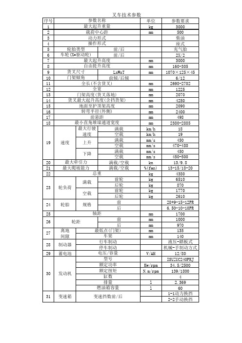
序号 1 2 3 4 5 6 7 8 9 10 11 12 13 14 15 16 17 18 参数名称 最大起升重量 载荷中心距 动力形式 操作形式 轮胎类型 前/后 车轮(X=驱动轮) 前/后 最大起升高度 自由提升高度 货叉尺寸 LxWxT 门架倾角 前倾/后倾 全长(不含货叉) 全宽 门架高度(货叉落地) 货叉最大起升高度(含挡货架) 地面至护顶架高度 转弯半径(外侧) 前悬距 最小直角堆垛通道宽度 最大行驶 满载 速度 空载 满载 速度 上升 空载 满载 下降 空载 最大牵引力 满载/空载 最大爬坡能力 满载/空载 总重 前轮 满载 后轮 轮负荷 前轮 空载 后轮 前 轮胎 规格 后 轴距 前 轮距 后 离地 最低点(门架) 间隙 车架 行车制动 制动器 停车制动 蓄电池 电压/容量 型号 额定功率 额定扭矩 发动机 缸数 排量 燃油箱容量 变速箱 变速挡数前/后 单位 kg mm 参数要求 3000 500 柴油 座式 充气胎 2X/2 3000 160-305 1070×125×45 6/12 2698-2702 1225 2070 4250 2090 2400 498 2380-2885 18 19 450 470-480 450 450-500 13/9.8 13-15/18-20 4380 6510 870 1770 2610 28*9-15-12PR 6.50-10-10PR 1700 1000 970 135 140 液压-踏板式 机械-手制动方式 12/80 ISUZUC240PKJ 34.5/2500 139/1800 4 2.369 60 1-1动力换挡 2-2手动换挡
mm mm mm mm mm mm mm mm mm mm mm km/h km/h mm/s mm/s mm/s mm/s kn %(fan) kg kg kg kg kg
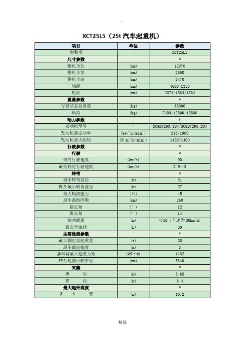
25t汽车起重机参数(XCT25L5)
27
最大爬坡能力
(%)
45
最小离地间隙
(mm)
260
接近角
(°)
12
离去角
(°)
14
制动距离
(m)
≤10(车速为30km/h)
百公里油耗
(L)
30
主要性能参数
*
最大额定总起重量
(t)
25
最小额定幅度
(m)
3
基本臂最大起重力矩
(kN·m)
1132
转台尾部回转半径
(mm)
3340
支腿
*
纵向
(m)
5.65
XCT25L5(25t汽车起重机)
项目
单位
参数
参数项
-
XCT25L5
尺寸参数
*
整机全长
(mm)
12870
整机全宽
(mm)
2550
整机全高
(mm)
3470
轴距
(mm)
4600+1350
轮距
(mm)
2074/1834/1834
重量参数
*
行驶状态总质量
(kg)
33000
轴荷
(kg)
7400/12800/12800
横向
(m)
6.4
最大起升高度
*
基本臂
(m)
10.2
最长主臂
(m)
41
最长主臂+副臂
(m)
50.2
最长主臂+副臂+加长节
(m)
起重臂长度
*
基本臂
(m)
10.8
最长主臂
(m)
约翰迪尔各项参数

1.96~27.21
变速箱挡位数(前进+倒退)
8+2
最小离地间隙 mm
310
外形尺寸 mm
3505×1590×2030
最小使用质量 kg
1900(结构质量、油、水、驾驶员质量75kg)
拖拉机 504
发动机型号
A498BT-22
发动机型式
直列、立式、四缸、四冲程、水冷、直喷式燃烧室
缸径×行程 mm
350
外形尺寸 mm
3510×1590×2050
最小使用质量 kg
1715(结构质量、油、水、驾驶员质量75kg)
拖拉机 450
发动机型号
A495BT
发动机型式
直列、立式、四缸、四冲程、水冷、直喷式燃烧室
缸径×行程 mm
95×105
标定功率 kW
33.1
燃油消耗率 g/kW?h
≤260
离合器型式
干式、单片、常接合、非独立操纵、单作用
液压输出多路阀
单组或双组(选配)
液压悬挂机构
三点后悬挂、Ⅰ类
提升能力 kN
≥10.3
最大牵引力 kN
≥18
动力输出转速 rpm
540和720,540和1000(选配)
行驶速度 km/h
2.31~26.74
变速箱挡位数(前进+倒退)
8+2
最小离地间隙 mm
315
外形尺寸 mm
3920×1770×2100
540/720 ;540/1000
行驶速度 km/h
2.190~28.128
2.190~28.128
变速箱挡位数(前进+倒退)
M250技术参数

1.外形尺寸:12.68m(含配重)*7.91m(履带外沿)*11.22m(含搬起架)2.回转速度:2.0rp/min 行走速度:2.01km/h 拖曳力:30% 3.主臂提升速度:2min40s 0—82°(41.44m主吊臂)4. 基本臂长:21.3m 主臂全臂:91.4m4.塔式工况:主臂最长:70.1m 主臂最短:24.4m副臂最长:61.0m 副臂最短:21.3m5.钢丝绳:起吊用6*31,EIPS常规布置,普通捻Φ29,624.84m;单绳320.04m,辅助绳:624.84m变幅用:6*26,EIPS交臂布置,混合捻Φ29,299.18m6.柴油发动机为康明斯发动机型号:NTA855—C4507.主臂跟部轴心线到回转中心距离:1.98m1.外形尺寸:10.18m(含配重)*6.67m(履带外沿)*3.77m(含搬起架)2.回转速度:2.2/1.1rp/min 行走速度(高/低):1.2/0.6km/h 尾部回转半径:6.04m 接地比压:1.03/cm23.提升、落钩,副臂变幅提升和爬杆速度:90/60/45/30m/min 塔臂变幅提升和爬杆速度:25 m/min4.基本臂长:18.29m 主臂全臂:82.30m5.塔式工况:主臂最长:56.69m 主臂最短35.35m 主臂拉绳:Φ36副臂最长:45.72m 副臂最短27.43m 副臂拉绳:Φ32 6.钢丝绳:主卷扬:335m Ф26 19+39*7 副卷扬:260m起重臂卷扬:280m Ф20 7*7+6*WS(31)0/0主变、付变副拉绳:Ф32 付臂变副拉绳Ф367.柴油发动机为三菱发动机:型号:6D22—TC 功率:216.1千瓦/2000rp/min8. 主臂跟部轴心线到回转中心距离:1.40m7350技术参数1.外形尺寸:14.655m(含配重)*8.72m(履带外沿)*4.29m(至驾驶室顶)2.回转速度: 1.3rp/min 行走速度:1.0/0.4 km/h 3.起升卷扬机起升、降落速度(前、后): 130---3m/min 主变幅卷扬机起升、降落速度: 44---2m/min副变幅卷扬机起升、降落速度: 28---2m/min 4.主臂工况:基础杆长:18m 重臂最小长度:78m 组合主臂工况:最小长度:30m 最大长度:96m5.塔式工况:标准工况:塔臂24——72m 副臂:24——66m重型起重工况:塔臂30——72m 副臂:24——66m超级起重工况:塔臂30——78m 副臂:24——66m6.钢丝绳:前、后升卷扬机:G{1×S(19)+39×7},Ф28 790m主、副变幅卷扬机:G IWRC 6×WS(31),Ф26 580m和440m HL/SHL卷扬机:GIWRC 6×WS(31),Ф26 640m主臂拉索直径均为44mm,副臂拉索及撑臂直径均为48mm 7.柴油发动机为日野发动机型号:K13C-TV 功率:294 kw/2000rp/min8. 主臂跟部轴心线到回转中心距离:1.60mKR—500型轮胎吊技术参数1.外形尺寸:11.9m*3m*3.77m 车辆总重:37,000kg2. 液压油箱:560L 燃油箱:300L3.最高行车速度:53 km/h 驱动系统:4*4 最小转弯半径:6.2m 4.转向方式:2轮转向、4轮转向及蟹行运动5.臂杆长度:9.2m—33.8m(5节臂杆)臂杆变幅角度:0—82°起臂速度:46s(0—82°)伸臂速度:102s(9.2m—33.8m)回转速度:2.9rp/min6.卷扬绳:主卷筒型式:U4*SeS(39)(非自转性)Ф18mm 长度:190m 付卷筒型式:U4*SeS(39)(非自转性)Ф18mm 长度:160m 7.轮胎尺寸:505/95R25 ROAD186E8.柴油发动机为三菱发动机型号:6D22T型功率:199kw/2200rp/min50t履带吊技术参数1.外形尺寸:6.745m(含配重)*4.3m(履带外沿)*3.08m(至驾驶室顶)2.回转速度:2.7rp/min 行走速度:1.1 km/h3.起升卷扬机起升、降落速度(前、后): 70---35m/min 变幅卷扬机起升、降落速度: 45m/min 4.主臂工况:组合主臂工况,最小长度:13m 最大长度:52m5.爬坡能力:20°6.钢丝绳:起重卷扬机:6*Fi(29)—20 [C种] Ф20 170m变幅卷扬机:6*Fi(29)—16 [C种] Ф16 150m拉绳:7(19)股(1+6+12)金属绳芯Ф397.柴油发动机为上海柴油机厂型号: 6135K-15 功率:128.7kw/2000rp/min 喷油泵型号:BH6B100YS49C 调速器型号:TQ250—1000B48B8.尾部回转半径:4m 接地比压:0.69 kg/cm2QY20A汽车吊技术参数1.整体外形尺寸:11.37m(全长)*2.5m*3.415m 9.057m(下车长)*2.5m*3.415m接近角/离去角(°):20/13 前、后桥中心距:4.6m中、后桥中心距:1.35m 车辆总重:23,910kg2.最高行车速度:60 km/h 最小转弯半径:12m 最大爬坡度:26.3% 制动距离(30 km/h):9.5m3. 最大起重量:20,000kg 主副钩起升速度:0—130 m/min最大起重力矩(t*m)基本臂:60 最长主臂:42最大起升高度(m)基本臂:10.1 最长主臂:24.8主臂+副臂:32.84. 变幅时间(s):起臂≤44 落臂≤31 伸臂≤88 缩臂≤65支腿时间(s):水平全伸≤27 水平全收≤19垂直全伸≤32 垂直全收≤185.回转速度(r/min):0—2 支腿跨距纵向:4.8m 横向:5.6m 6.柴油发动机型号及编号:X6130QT7g(杭柴) 1571 功率:154±7.7kw/2100rp/min油泵型号:NP—PE6P115/321RS1NP166调速器型号:NP—EP/RFD200/1350PF7CCR7.变速箱型号:5J80TA—B 转向机型号:FDZ125C8.轮胎尺寸:11.00—20 18PR 轮辋规格:8.0—201.外形尺寸:13.35m*2.7m*2.25m 前悬/后悬:2.21m*3.74m 轴距:1.500m +4.600m +1.300m 接近角/离去角(°):17/18 轮距(前、中、后):2.036m/1.861m 最小离地间隙:0.29m 车辆总重:14,540kg 载重量:25,000kg2.最高行车速度:65 km/h 最小转弯半径:12m 最大爬坡度:26.3% 制动距离(30 km/h):9.5m3.柴油发动机型号:WD615.67A 功率:206kw/2200rp/min 缸径*行程:126*130 燃油箱:380L 压缩比:15.5:1 底盘型号:DJZ14004.轮胎尺寸:11.00—20 18层尼龙帘布轮辋规格:8.0—201.外形尺寸:13.84m*2.7m*2.3m 前悬/后悬:2.21m*3.74m 轴距:1.500m +5.0650m +1.350m 接近角/离去角(°):17/18 轮距(前、中、后):2.006m/1.8m 最小离地间隙:0.29m车辆总重:15,300kg 载重量:30,000kg2.最高行车速度:65 km/h 最小转弯半径:13m 最大爬坡度:26.3% 制动距离(30 km/h):9.5m3.柴油发动机型号:WD615.68A 功率:225kw/2200rp/min 缸径*行程:126*130 燃油箱:380L 压缩比:15.5:1 底盘型号:DJZ14504.轮胎尺寸:12.00—20 18层尼龙帘布轮辋规格:8.5—2040t平板车技术参数1.主车外形尺寸:9.30m*2.5m*3.064m轴距:3.8m +1.4m 接近角/离去角(°):27.5/17.5轮距(前、后):2.006m/1.8m 油耗:50 L/100 km2.最小行车速度:3.5 km/h 最小转弯半径:9.4m3.柴油发动机型号:康明斯NTC—2904.轮胎尺寸:12.00—20 18层尼龙帘布轮辋规格:8.5—20CQ1262红岩车技术参数1.主车外形尺寸:10.971m*2.428m*2.995m货箱内部尺寸:8.530m*2.368m*0.580m(货物中心距中桥距离)轴距:4.95m + 1.4m 接近角/离去角(°):19/15轮距(前、后):2.006m/1.810m 最小离地间隙:0.316m 最大总质重:25,700kg 最大装载量:14,400kg2.最高行车速度:87 km/h 最小转弯半径:≤23m 最大爬坡度:26% 油耗:33 L/100 km驱动型式:6*43.柴油发动机型号:WD615.61A 功率:191kw/2600rp/min 离合器型号:FS,ф420 型式:干式,单片,周置弹簧变速箱:ZFS6—90 转向器:ZF80434.轮胎尺寸:11.00—20*18PR 轮辋规格:8.0—20DBQ3000t*m塔吊技术参数1.主臂工况时:全程变幅时间:7min搬起:14.8min 变幅范围:35°28″21′—78°15″18′主钩:起重量Qmax=160,000kg 幅度R=13—21m 高度H=49m 起重量Q=27,500kg 幅度Rmax=60m 高度H=43m 起升力矩:Tmax=33600t*m Q=160,000kg 高度H=49m 2.塔式工况:全程变幅时间:11min变幅范围:35°28″21′—78°15″18′主钩:起重量Qmax=100,000kg 幅度R=16—18m 高度H=107m 起重量Q=20,000kg 幅度Rmax=60m 高度H=89.6m 起升力矩:Tmax=22560t*m Q=94,000kg 高度H=92.5m 3.回转速度:V=0.137rp/min回转角度:0—360º行走速度:V=10m/min 行走范围:150m行走轮总数/轮数:48/32 轨距:12m 基距:11m轮压Pmax=28,000kg 侧向Pmax=4,000kg 6A的涡流制动器4.起升机构:提升V=58.5—107.8m/min 下降V=12.6—126.4m/min电动机:YZR315M—8 100kw JZ2—H—72—4/8 60kw减速机:ZL130—17Ⅱ速比:46.22 制动器:YWZ500/90 钢丝绳:6W(19)+7*7—32.5—155—Ⅰ—光—右交 1270m 5.行走机构:电动机:YZ160M1—6 6.3kw 8个减速机:ZQ40—20Ⅵ速比:19.99 制动器:TJ2—200/100 6.回转机构:电动机:JZR241—8 11kw 2个 A1—5624A3 0.12kw 2个专用立式减速机速比:204.56 脚踏液压式制动器:Ф350 7.副变幅:电动机:YZR225M—8 26kw减速机:ZQ—100+250 速比:163.38 制动器:YWZ—400/45 钢丝绳:6W(19)+7*7—32.5—155—Ⅰ—光—右交 400m 8.主变幅:电动机:YZR225M—8 42kw 2个减速机:ZQ85—31.5Ⅸz 速比:30.52 制动器:YWZ—400/90 钢丝绳:6W(19)+7*7—32.5—155—Ⅰ—光—右交 950m 9.电缆绞盘:电动机:JLJ32—1.6/6 1.64kw减速机:BW2—11 速比: 11 制动器:YWZ—200/25 10.钢轨型号:P7011.其它:主臂高度限制器钢丝绳:1*19—4—140—Ⅰ 13m 塔式高度限制器钢丝绳:1*19—4—140—Ⅰ 7m输入拖缆:YCW—500 3*95+1*35 100m1.主钩:Q=60,000kg H=14.7m V=4.29m/min 电动葫芦:Q=10,000kg H=15.0m V=8.0m/min2.大车运行速度:V=22.07m/min 小车运行速度:V=26.7m/min 3.安全开关:大车行走机构:LX22—1 起升卷扬机:LX22—3 牵引卷扬机:LX7—1 输入拖缆:YC—3*50+1*16 120m 4.总重量:98,744kg 桥架:47,540kg 悬臂:8m5.起升卷扬机:电动机:JZR262—10 45kw 制动器:YDWZ—400/100减速机:JZQ750—Ⅲ—3C 速比:31.5钢丝绳:6*37—24—140 510m6.牵引卷扬机:电动机:JZR242—8 16kw 制动器:TJ2—300/200减速机:JZQ500—Ⅲ—3C 速比:31.5钢丝绳:6*37—15—155 210m7.大车行走机构:电动机:JZR241—8 2*11kw 制动器:TJ2—300/200减速机:JZQ500—Ⅲ—3/4C8.大车轨距:42m 轮距:1.2m 7.5m 车轮直径:Ф0.75 m 钢轨型号:P50或P43 最大轮压:20,000kg9.小车轨距:2.6m 轮距:1m 车轮直径:Ф0.40m 钢轨型号:P24 电动葫芦:I30# /I40#(CD5/CD10)1.主钩:Q=40,000kg H=14.62m V=3.85m/min 电动葫芦:Q=5,000kg H=14.63m V=8.0m/min2.大车运行速度:V=22.2m/min 小车运行速度:V=26.8m/min 3.安全开关:大车行走机构:LX22—1 起升卷扬机:LX22—3 牵引卷扬机:LX7—1 输入拖缆:YC—3*35+1*10 100m 4.总重量:71,804kg 桥架:41,336kg 悬臂:8m5.起升卷扬机:电动机:JZR52—8 30kw 制动器:YDWZ—400/100减速机:JZQ750—Ⅲ—3C 速比:31.5钢丝绳:6*37+1—17.5 540m6.牵引卷扬机:电动机:JZR22—6 7.5kw 制动器:TJ2—200减速机:JZQ400—Ⅱ—3—C 速比:40.17钢丝绳:6*37+1—15.5 260m7.大车行走机构:电动机:JZR22—6 7.5kw 制动器:TJ2—200减速机:JZQ400—Ⅲ—3—C 速比:31.58.大车轨距:42m 轮距:7.18m 车轮直径:Ф0.75 m 钢轨型号:P50或P439.小车轨距:2.5m 轮距:1.6m 车轮直径:Ф0.40m 钢轨型号:P24 电动葫芦:I30#1.主钩:Q=20,000kg H=12m V=7m/min 电动葫芦:Q=5,000kg H=12m V=8m/min2.大车运行速度:V=28.5m/min 小车运行速度:V=25m/min 电动葫芦行走:V=20m/min3.安全开关:大车行走机构:LX22—1 起升卷扬机:LX22—3 牵引卷扬机:LX7—1 输入拖缆:YC—3*35+1*10 100m 4.总重量:49,800kg 桥架:26,344kg 悬臂:5m5.起升卷扬机:电动机:YZR250M1 25kw 减速机:ZQH75—50—Ⅳ—CA 制动器:YZW—300/100钢丝绳:6W(19)—17.5—70—I—光—右 510m6.牵引卷扬机:电动机:YZR160M1 5kw 减速机:ZQH50—50—Ⅳ—CA制动器:YWZ200/25钢丝绳:6W(19)—11—15—光—右交 260m7.大车行走机构:电动机:YZR132M1 3.5kw 制动器:YWZ—200/25减速机:ZQH35—25—Ⅲ/Ⅳ8.大车:轨距:32m 钢轨型号:P439.小车:钢轨型号:P24 电动葫芦:I30#。
一种250t轮胎式上电下液搬运机
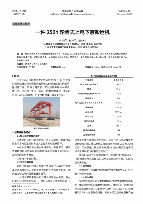
第2卷第12期2020年12月智能建筑与工程机械Intelligent Building and Construction MachineryVol.2No.12December2020工程机械与智控一种2501轮胎式上电下液搬运机王大江",张宇I?,冯扶民"(1.秦皇岛天业通联重工科技有限公司,河北秦皇岛066000;2.河北省重型装备工程技术中心,河北秦皇岛066000)摘要:轮胎式搬运机用于预制梁场的搬运工作,机动灵活。
主要由机械系统、卷扬系统、液压系统及电气控制系统组成,其起升速度可调,实现无级调速,液压控制系统精度高,稳定性好,电气控制系统抗干扰能力强,采用国际领先的CAN 总线技术实现。
关键词:搬运机;液压;总线技术中图分类号:TH137文献标识码:A文章编号:2096-6903(2020)12-0058-020概述本TTB250型轮胎式搬运机适用于20〜40m等多种预制混凝土箱梁或者其他载荷从预制场台座内的起吊、搬运等工作,设备方便灵活,可以实现多种转向模式,如八字、半八字,直行、斜行、90。
转向等模式;搬运机采用CAN总线技术、抗干扰能力强,如图1所示。
1主要结构及组成1.1搬运机主要技术参数本搬运机采用门架式结构,大车支腿部分跨度可以满足同等吨位运梁台车进入进行实时取梁操作[1]0本轮胎式搬运机主要由机械部分、悬挂部分、具有负载敏感特点的液压驱动系统及移动车辆专用的CAN 总线控制系统等组成。
主要技术参数见表lo1.2液压控制系统轮胎式搬运机的液压系统主要由闭式大车走行系统及驱动悬挂转向、辅助支腿顶升的开式系统等组成,本系统为恒功率的负载敏感系统[2]o大车行走驱动系统的动力源为柴油发电机组。
发电机组为异步电机提供动力,电机为液压闭式泵提供动力。
收稿S期:2020-10-21作者简介:王大江(1982—),男,河北承德人,硕士研究生,高级工程师,从事特种车辆及起重机的电气控制等工作。
黑鹰汽车工具手册 - 12吨和25吨店内压力机操作指南说明书

Model Capacity BH8122 12 Ton BH820225 TonShop PressOperating Instructions & Parts ManualSFA Companies10939 N. Pomona Ave. Kansas City, MO 64153******************************Figure 1 - Shop Press Components (BH8202 shown)SPECIFICATIONSModel Capacity Dimensions(W x D x H)Min. Working SpaceMax. WorkingSpace Bed PositionHydraulic StrokeBH812212 Ton 28" x 28" x 59"4 5/8"36 3/8"86"BH820225 Ton2 1/2"34 1/4"(1/4NPT)Hydraulic HoseSAFETY and GENERAL INFORMATIONSave these instructions. For your safety, read, understand, and follow the information provided with and on this product before using. The owner and operator of this equipment shall have an understanding of this product and safe operating procedures before attempting to use. The owner and operator shall be aware that use and repair of this product may require special skills and knowledge. Instructions and safety information shall be conveyed in the operator's native language before use of this jack is authorized. If any doubt exists as to the safe and proper use of this jack, remove from service immediately.Inspect before each use. Do not use if broken, bent, cracked or damaged parts are noted. Any press that appears damaged in any way, or operates abnormally shall be removed from service immediately. If any component of this product has been or suspected to have been subjected to a shock load (a load dropped suddenly, unexpectedly upon it), immediately discontinue use until checked by a factory authorized service center (contact distributor or manufacturer for list of authorized service centers). It is recommended that an annual inspection be done by qualified personnel. Labels and Operator's Manuals are available from manufacturer.PRODUCT DESCRIPTIONShop Press is designed for automotive, truck, implement, fleet, and industrial repair shops where pressing, bending, straightening, forming, holding is required. Typical applications include installation and removal of alternator and power steering pump bearings, axle bearings, transmission bearings, seal, driveshaft bearings and u-joints and others. It is not intended for use as an assembly table or as fixture stand used to secure a large, final assembly component. WARNING : To reduce the risk of personal injury and/or property damage, ensure that the rated working pressure of each pressurized attachment be equal to or greater than the rated working pressure developed by the hydraulic pump.PREPARATIONBefore Use1. Verify that the product and application are compatible, if in doubt call Blackhawk technical service (888) 332-6419.2. Before using this product, read the operator's manual completely and familiarize yourself thoroughly with the product, its components and recognize the hazards associated with its use.3. To familiarize yourself with basic operation of hand pump, turn the release valve:a. Clockwise until firm resistance is felt to further turning. This is the ‘CLOSED ’ release valve position used to extend the ram.b. Counter-clockwise, but no more than 1/2 turn from the closed position. This is the ‘OPEN ’ release valve position used to retract the ram.4. With release valve opened, remove the oil filler screw. Ensure the oil level is within 1/4" (6mm) of the opening. Reinstall the oil filler screw. Assembly (Refer to Figure 2)Note: Do not tighten any bolts unless told to do so.1. Attach base legs (1) to upright channels (2) with bolts, lock washers and nuts (3). Hand tighten only.2. Attach lower cross member (4) to upright channels (2) with bolts, lock washers and nuts (3).3. Attach support links (5) to the base (1) and upright channels (2) with bolts, lock washers and nuts (3).4. Carefully slide bed frame (6) down to lowest possible position between the upright channels (2).5. Slide head plate (7) to into upper cross members (8). Then, secure with bolts (9).6. Attach the upper cross members assembly (8) to the upright channels (2) with bolts, flat washers, lock washers and nuts (10).7. Thread the ram (11) to head plate (7) on upper cross members (8).8. Attached pump support bracket (12) to upright channel (2) with three bolts, lock washers and nuts (3).9. Tighten all aplicable nuts and bolt assemblies.10. Place the hand pump (13) on pump support bracket (12).11. To hold the pump, attach the fixed backets (14) and secure with bolts, lock washers and nuts (3).12. Connect the male coupler end of hydraulic hose (15) to the female coupler of the ram (11) to complete the connections.Model BH8122Size of Hardware Kits Qty3bolt M10x2519lock washer M1019nut M10199bolt 10x25210bolt M16x1154flat washer M168lock washer M164nut M164Figure 2 - Assembly IllustrationModel BH8202Size of Hardware Kits Qty 3bolt M10x2519lock washer M1019nut M10199bolt 10x25210bolt M16x1504flat washer M168lock washer M164nut M16413. Carefully bring the bed frame (6) up and secure it with pins (16).14. Place the Arbor Plates (17) on Bed Frame (6).15 When necessary, replace the saddle of ram (11) with the bearing punch (18).16.The press is now ready to use.Caution: Before disassembly, carefully slide bed from down to its fully lowered position.OPERATIONWear ANSI approved eye protection. Never stand directly in front of loaded press. fully following Keep hands and feet from bed area at all times.4. Close release valve by turning it clockwise firmly, and pump the handle to extend the ram until ram nears workpiece..5. Align ram and workpiece to ensure center-loading.6. Apply load to workpiece by pumping handle. Do not overload workpiece .7. Stabilize workpiece in a manner which will not allow it to inadvertently fall from the bed once the load is removed. 8. To remove workpiece, turn release valve counter-clockwise to retract the ram.Note: To protect your ram, do not continue to operate pump after it is fully extended or retracted.MAINTENANCEBefore each use, inspect press for damage. Do not use if bent, broken, cracked, leaking or otherwise damaged components are noted. Periodically, lightly oil all moving parts, including the pump piston and ram.Adding/Changing oil to hand pumpImportant: Use only good grade hydraulic oil. Avoid mixing different types of fluid and NEVER use brake fluid, turbine oil, transmission fluid, motor oil or glycerin. Improper fluid can cause premature failure of the ram and pump and the potential for sudden and immediate loss of load. Mobil DTE 13M or equivalent recommended.For best results, change fluid once a year.1. Depressurize and disconnect hydraulic hose from application.2. Remove oil filler screw located on top of the reservoir.3. Pour used fluid into a sealable container.Note: Dispose of hydraulic fluid in accordance with local regulations.4. With pump in its upright, horizontal position, use a small funnel to fill reservoir to within 1/4” (6 mm) of the opening.5. Wipe up any spilled fluid and reinstall the vented oil filler plug.R ust preventionCheck ram and hand pump piston for signs of rust on a regular basis. Clean as needed with a lint free, oil saturated cloth. Never use sandpaper or abrasive material on these surface.How to remove faulty coupler:If ram does not retract: Depressurize pump and hose, then remove the ram from application. Disconnect and replace with new coupler.Important:TROUBLESHOOTINGSymptom Possible Causes Corrective ActionRam will not press load• Release valve not tightly closed• Overload condition• Faulty/ Loose couplers• Oil lever in pump is low • Ensure release valve tightly closed •Remedy overload condition• Replace/ Tighten couplers• Fill and bleed systemRam bleeds off after press operation • Oil lever in pump is low•Ram malfunction• Fill and bleed system•Contact Blackhawk Tech. ServiceRam will not retract after unloading • Pump reservoir overfilled• Linkage binding• Drain fluid to proper level• Clean and lubricate moving partsPoor lift performance• Oil level low•Air trapped in system • Ensure proper oil level •Bleed systemOil leak from ram • Ram malfunction•Contact Blackhawk Tech. ServiceREPLACEMENT PARTSNot all components of the press are replacement items, but are illustrated as a convenient reference of location and position in the assembly sequence. When ordering parts, please give the Model number and parts description. Call or write for current pricing: SFA Companies, 10939 N. Pomona Ave. Kansas City, MO 64153, U.S.A.Tel:(816)891-6390Fax:(816)891-6599E-Mail:******************************Item Part# for model:Description QtyBH8202BH81221T125-00001-000T184-00001-000Upper Cross Member (1pc for 65123)22T125-00003-000T184-00008-000Punch13T125-00007-000T184-00007-000Arbor Plates (pair)14T125-02000-000T184-02000-000Bed Frame15T125-01000-000T184-01000-000Support Pin26T125-00002-000T184-00002-000Upright Channel27T184-00006-000Lower Cross Member18T184-00004-000Support Link29T184-00005-000Base Leg210T184-00003-000Pump Bracket111F100-90004-K01Hand Pump112T125-00008-000Fixed Bracket213F040-90107-K02Oil Filler Screw114T125-03000-000T184-03000-000Head Plate115F250-30000-000F100-30000-000Ram116F040-90009-K04Coupler, Female 1/4NPT1F040-90009-K05Coupler, Male 1/4NPT117F100-90009-K01Pump Handle1-BH8200BH8120Pump & Ram Assembly (#11 & 15)--T125-04000-000T184-04000-000Hardware Kit-Figure 4 - Replacement Parts IllustrationONE YEAR LIMITED WARRANTYFor a period of one (1) year from date of purchase, SFA Companies will repair or replace, at its option, without charge, any of its products which fails due to a defect in material or workmanship under normal usage. This limited warranty is a consumer's exclusive remedy.Performance of any obligation under this warranty may be obtained by returning the warranted product, freight prepaid, to SFA Companies Warranty Service Department, 10939 N. Pomona Ave., Kansas City, MO 64153.Except where such limitations and exclusions are specifically prohibited by applicable law,(1) THE CONSUMER'S SOLE AND EXCLUSIVE REMEDY SHALL BE THE REPAIR OR REPLACEMENT OF DEFECTIVE PRODUCTS AS DESCRIBED ABOVE.(2) SFA Companies SHALL NOT BE LIABLE FOR ANY CONSEQUENTIAL OR INCIDENTAL DAMAGE OR LOSS WHATSOEVER.(3) ANY IMPLIED WARRANTIES, INCLUDING WITHOUT LIMITATION THE IMPLIED WARRANTIES OF MERCHANTABILITY AND FITNESS FOR A PARTICULAR PURPOSE, SHALL BE LIMITED TO ONE YEAR, OTHERWISE THE REPAIR, REPLACEMENT OR REFUND AS PROVIDED UNDER THIS EXPRESS LIMITED WARRANTY IS THE EXCLUSIVE REMEDY OF THE CONSUMER, AND IS PROVIDED IN LIEU OF ALL OTHER WARRANTIES, EXPRESS OR IMPLIED.(4) ANY MODIFICATION, ALTERATION, ABUSE, UNAUTHORIZED SERVICE OR ORNAMENTAL DESIGN VOIDS THIS WARRANTY AND IS NOT COVERED BY THIS WARRANTY.Some states do not allow limitations on how long an implied warranty lasts, so the above limitation may not apply to you. Some states do not allow the exclusion or limitation of incidental or consequential damages, so the above limitation or exclusion may not apply to you. This warranty gives you specific legal rights, and you may also have other rights, which vary from state to state.SFA Companies Array 10939 N. Pomona Ave. Kansas City, MO 64153816-891-6390******************************。
三一25C5-1性能表

三一25C5-1性能表STC250C5-1汽车起重机采用上柴大马力发动机,法士特9档带同步器变速箱,最大爬坡度42%。
双变量泵智能流量分配液压系统.型号:STC250C5-1整机尺寸:长×宽×高12.611×2.494×3.339米最大行驶速度 80km/h最大爬坡度 30%发动机型号东风康明斯ISLe290 30,潍柴WP10.270,上柴SC8DK260Q3最大输出功率 290kW吊升能力额定起重量 25吨额定起重力矩 962KN.m额定起重力矩全伸臂 544KN.m最小工作幅度 3米最大起升高度-基本臂 10.9米最大起升高 33.9米最大起升高度-基本臂+副臂 42米起重臂长度-基本臂 10.65米起重臂长度-全伸臂 33.5米起重臂长度-基本臂+副臂 41.5米作业参数主卷扬最大起升速度 130m/min副卷扬最大起升速度 130m/min支腿跨距:纵向×横向6×5.1米臂长长性能强五节大截面U型主臂,主臂全伸42.5米,行业领先,作业覆盖范围广;单板臂头及紧凑式臂尾,臂间搭接长度行业领先承载能力强,起重臂上翘设计,吊载挠度小。
高承载能力底盘全新2.55米车宽底盘,加高加宽矩形变截面车架,吊载抗扭抗弯能力全面加强;采用上柴大马力发动机,法士特9档带同步器变速箱,最大爬坡度42%。
双变量泵智能流量分配液压系统负载敏感系统:采用大流量双联变量柱塞泵、流量充足但无浪费,作业高效、节能环保;智能流量分配:使用全新智能流量分配主阀,组合动作时变幅独立,不受其他动作干扰,大幅提升组合动作操控性。
采用阀后补偿技术,流量按需分配,卷扬单绳最低稳定速度1.98m/min,回转最低稳定速度0.18° /s,可实现mm 级精准吊装;功率管理:全新动力匹配及功率控制,作业工况发动机转速降低,节能降噪;集成回转缓冲控制:融合升压缓冲、顺序制动及自由滑转技术,回转启停柔和平稳。