深圳兆威24毫米行星齿轮减速电机介绍
微型齿轮减速电机参数及规格
微型齿轮减速电机参数及规格
1.微型齿轮减速电机概述
兆威机电的微型齿轮减速电机是微型电机驱动闭式传动减速装置(又称微型齿轮减速马达),就是减速机和电机(或马达)的组合体,用来降低转速和增大转矩,以满足机械设备工作的需要。
而这种组合也可以称为齿轮减速机或者是齿轮减速马达等。
一般来说,微型齿轮减速电机都是由专业的减速电机生产厂进行组装后成套供应的,如果分开两部分购买的话在结合度方面会大大受损。
2.微型齿轮减速电机的参数
兆威机电的微型齿轮减速电机详细:
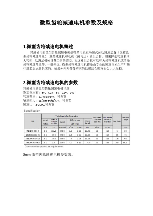
额定电压有:3v、4.2v、5v、12v、24v
转速范围:11-4318rpm,可调节
输出矩力:1gf.cm-50kgf.cm,可调节
减速比:2-2000,可调节
3mm微型齿轮减速电机参数表。
38mm微型齿轮减速电机参数表。
3.微型齿轮减速电机的规格
兆威机电全系列外径尺寸微型齿轮减速电机:3.4mm、4mm、6mm、8mm、10mm、12mm、16mm、24mm、28mm、30mm、38mm,实际外径尺寸可定制。
减速电机型号参数规格介绍解读
兆威机电:/减速电机型号参数、型号、规格介绍减速电机概述减速电机是指减速机和电机(马达)的集成体。
这种集成体通常也可称为齿轮马达或齿轮电机。
通常由专业减速机厂家一站式开发人成,成套供货;减速电机按照功率分为大功率减速电机好小功率减速电机,分别应用于不同的领域。
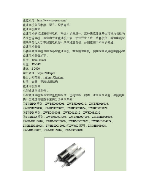
减速电机参数小功率减速电机也称为小型减速电机、微型减速电机,例如深圳兆威机电的小型减速电机参数如下:尺寸:3mm-38mm电压:3V-24V速比:2-2000输出转速:5rpm-2000rpm输出力矩范围:1gf.cm-50kgf.cm材质:金属、塑胶材质结构减速电机型号小型减速电机型号:小型减速电机型号主要是根据尺寸、齿轮结构、材质、速比来区分的,兆威机电的小型减速电机型号主要分为四大系列:①ZWBPD系列:ZWBPD006006、ZWBPD010010、ZWBPD016016、ZWBPD020020、ZWBPD022022、ZWBPD024024、ZWBPD028028②ZWPD系列:ZWPD008008、ZWPD012012、ZWPD032032③ZWBMD系列:ZWBMD003003、ZWBMD004004、ZWBMD006006、ZWBMD010010、ZWBMD020020、ZWBMD022022、ZWBMD024024、ZWBMD028028、ZWBMD032032 ④ZWMD系列:ZWMD008008、ZWMD012012、ZWMD016016、ZWMD038038兆威机电:/兆威机电:/减速电机规格减速电机性能特点1、大多数减速电机结构紧凑,体积小,造型美观,承受过载能力强。
2、传动比分级精细,选择范围广,转速型谱宽,范围i=2-28800。
3、能耗低,性能优越,减速器效率高达百分之九十六,振动小,噪音低。
4、通用性强,是用维护方便,维护成本低,特别是生产线,只需备用内部几个传动件即可保证整线正常生产的维修保养。
5、采用新型密封装置,保护性能好,对环境适应性强,可在有高温80度、低温-10度等恶劣环境中连续工作。
深圳兆威齿轮减速电机类型与特点及应用的分析
深圳兆威齿轮减速电机类型与特点及应用的分析
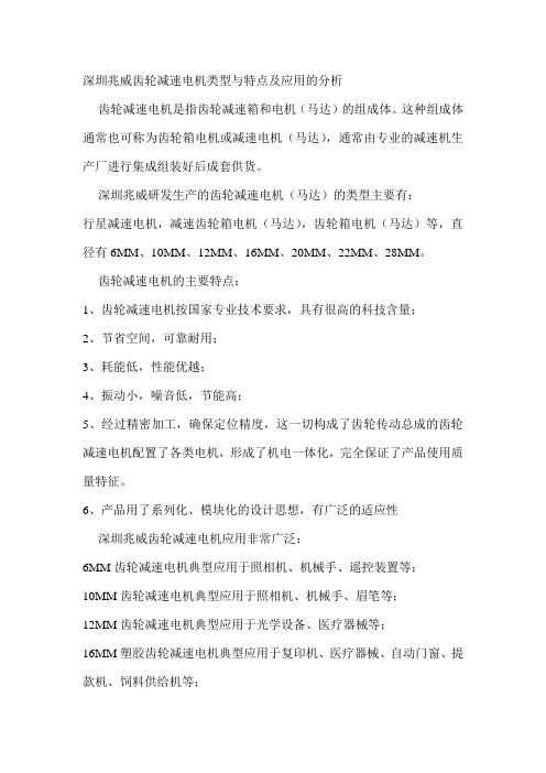
齿轮减速电机是指齿轮减速箱和电机(马达)的组成体。
这种组成体通常也可称为齿轮箱电机或减速电机(马达),通常由专业的减速机生产厂进行集成组装好后成套供货。
深圳兆威研发生产的齿轮减速电机(马达)的类型主要有:
行星减速电机,减速齿轮箱电机(马达),齿轮箱电机(马达)等,直径有6MM、10MM、12MM、16MM、20MM、22MM、28MM。
齿轮减速电机的主要特点:
1、齿轮减速电机按国家专业技术要求,具有很高的科技含量;
2、节省空间,可靠耐用;
3、耗能低,性能优越;
4、振动小,噪音低,节能高;
5、经过精密加工,确保定位精度,这一切构成了齿轮传动总成的齿轮减速电机配置了各类电机,形成了机电一体化,完全保证了产品使用质量特征。
6、产品用了系列化、模块化的设计思想,有广泛的适应性
深圳兆威齿轮减速电机应用非常广泛:
6MM齿轮减速电机典型应用于照相机、机械手、遥控装置等;
10MM齿轮减速电机典型应用于照相机、机械手、眉笔等;
12MM齿轮减速电机典型应用于光学设备、医疗器械等;
16MM塑胶齿轮减速电机典型应用于复印机、医疗器械、自动门窗、提款机、饲料供给机等;
16MM金属齿轮减速电机、20MM齿轮减速电机、22MM粉末冶金齿轮减速电机等典型应用于自动机械传动、医疗器械、广告旋转传动、银行提款机等;
28MM齿轮减速电机典型应用于光学设备、医疗器械、广告旋转传动、银行提款机等。
MMT-DC24DP10-35BL 使用说明书
MMT – DC24DP10-35BL使用说明书概述:DC 12V /24V /36V/48DP XXBL系列产品是采用专用模块,使控制和供电完全隔离,避免了低压大电流时对控制系统的干扰。
其优良的线性比例、比较宽的电压输入范围、突出的性能和调速比。
具有稳定、可靠的质量,使其得到广范的应用。
该系列产品适用于电瓶供电或直流供电的野外作业以及低压自动控制的场合。
目前已应用在军工、机器人、低压安全设备、教研设备等领域。
一、主要特点技术参数:1、输入电压:DC 24 V(工作范围18V-36V)2、输出电压:DC 0V----24V3、输出电流:DC 10A 20A 35A4、调速比1:805、环境温度: --10℃~+60℃6、环境湿度:相对湿度≤80RH。
(无结露)7、适用于稀土、永磁和他励电动机8、双闭环PI调节(电流电压)9、采用SMT技术、体积小10、电流设置和限制保护11、瞬时短路保护(50us)12、软启动/软停止设置功能13、快速停止功能14、低速启动力矩大15、可实现远程启停二、产品性能:1、具有较硬的机械特性,静差率1%。
2、具有较宽的调速范围(0—最大)。
3、具有较快的动态响应过程。
4、具有加、减速时自动平滑的过渡过程。
5、较好的挖土机特性,能将过载电流自动限止在设定值电流上。
6、可靠性高,结构紧凑,具有极高的性价比。
三、电位器调整说明(顺时针增大)1、限制调整:TORQUE可以限制驱动板最大输出电流,根据所选马达的额定电流调整该电位器,使驱动板的最大输出电流为马达额定电流的120%~200%。
2、力矩补偿调整:IR COMPIR COMP 电位器用于调整马达工作在不同的负载时,使其转速保持恒定。
3、软启动-----升速时间调整:ACCEL调整ACCEL可以确定马达从初始速度到设定速度的上升斜率(既上升时间,设定时间在0-10秒内可调)。
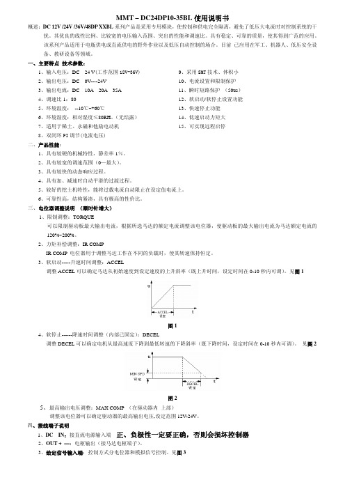
见图1图14、软停止------降速时间调整(内部已固定):DECEL调整DECEL可以确定电机从最高速度下降到最低转速的下降斜率(既下降时间,设定时间在0-10秒内可调)。
电动晾衣架直流电机参数
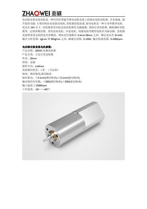
电动晾衣架直流电机是一种应用在智能升降电动晾衣架上的驱动电机齿轮箱,具有减速、提升扭矩功能,主要结构由直流驱动电机、齿轮箱组装而成,驱动电机是一种小功率微型电机,电压在24V以下,齿轮箱采用非标定制齿轮箱作为减速器,例如行星齿轮箱、蜗轮蜗杆齿轮箱等,定制参数范围,采用直流电机、步进电机、伺服电机等微型电机作为驱动源,齿轮箱是按照需求定制的技术参数的,例如直径规格在3.4mm-38mm之间,额定电压在3V-24V,输出力矩范围:1gf.cm到50Kgf.cm之间,减速比范围:5-1500;输出转速范围:5-2000rpm;电动晾衣架直流电机参数:产品名称:20MM金属齿轮箱产品分类:五金行星齿轮箱外径:20mm材质:金属旋转方向:cw&ccw齿轮箱回程差:≤3°(可定制)轴承:烧结轴承;滚动轴承轴向窜动:≤0.1mm(烧结轴承);≤0.1mm(滚动轴承)输出轴径向负载:≤30N(烧结轴承);≤50N(滚动轴承)输入速度:≤15000rpm工作温度:-20 (85)24MM金属减速齿轮箱产品分类:五金行星齿轮箱外径:24mm材质:五金旋转方向:cw&ccw齿轮箱回程差:≤2°(可定制)轴承:烧结轴承;滚动轴承轴向窜动:≤0.1mm;≤0.1mm输出轴径向负载:≤120N;≤170N 输入速度:≤15000rpm工作温度:-30 (100)定制参数、规格范围:尺寸规格系列:3.4mm、4mm、6mm、8mm、10mm、12mm、16mm、18mm、20mm、22mm、24mm、28mm、32mm、38mm;齿轮材质:塑胶齿轮箱、金属齿轮箱适用电机:直流无刷电机、直流有刷电机、步进电机电压范围:3V-24V功率范围:0.1W-40W输出力矩范围:1gf.cm到50Kgf.cm减速比范围:5-1500;输出转速范围:5-2000rpm;生产厂家深圳市兆威机电股份有限公司成立于2001年,是一家研发、生产精密传动系统及汽车精密注塑零组件的制造型企业,为客户提供传动方案设计,零件的生产与组装的定制化服务。
小功率微型精密行星齿轮减速机参数
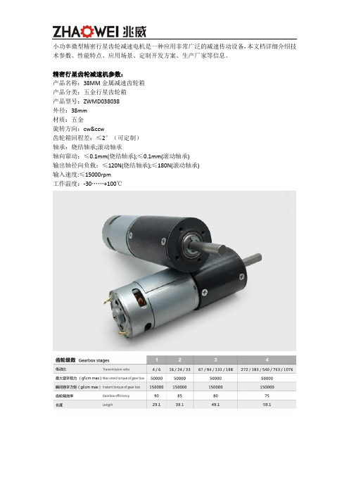
小功率微型精密行星齿轮减速电机是一种应用非常广泛的减速传动设备,本文档详细介绍技术参数、性能特点、应用场景、定制开发方案、生产厂家等信息。
精密行星齿轮减速机参数:产品名称:38MM金属减速齿轮箱产品分类:五金行星齿轮箱产品型号:ZWMD038038外径:38mm材质:五金旋转方向:cw&ccw齿轮箱回程差:≤2°(可定制)轴承:烧结轴承;滚动轴承轴向窜动:≤0.1mm(烧结轴承);≤0.1mm(滚动轴承)输出轴径向负载:≤120N(烧结轴承);≤180N(滚动轴承)输入速度:≤15000rpm工作温度:-30 (100)产品名称:24MM金属减速齿轮箱产品分类:五金行星齿轮箱产品型号:ZWBMD024024外径:24mm材质:五金旋转方向:cw&ccw齿轮箱回程差:≤2°(可定制)轴承:烧结轴承;滚动轴承轴向窜动:≤0.1mm;≤0.1mm输出轴径向负载:≤120N;≤170N 输入速度:≤15000rpm工作温度:-30 (100)非标定制精密行星齿轮减速机参数、规格范围:尺寸规格系列:3.4mm、4mm、6mm、8mm、10mm、12mm、16mm、18mm、20mm、22mm、24mm、28mm、32mm、38mm;材质系列:塑胶行星齿轮箱、金属行星齿轮箱电压范围:3V-24V功率范围:0.1W-40W输出力矩范围:1gf.cm到50Kgf.cm减速比范围:5-1500;输出转速范围:5-2000rpm;产品特点:体积小、噪音低、精度高、减速范围广、扭矩大、寿命长、效率高、兼具功率分流、多齿啮合独用的特性。
产品应用:小功率微型精密行星齿轮减速电机广泛应用在智能汽车、智能通讯、智能医疗、智能电子产品、智能机器人。
生产厂家深圳市兆威机电股份有限公司成立于2001年,是一家研发、生产精密传动系统及汽车精密注塑零组件的制造型企业,为客户提供传动方案设计,零件的生产与组装的定制化服务。
精密行星减速电机参数型号
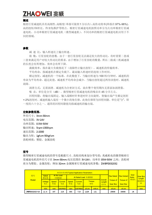
概述精密行星减速机具有高刚性、高精度(单级可做到1分以内)、高传动效率(单级在97%-98%)、高的扭矩/体积比、终身免维护等特点。
精密行星减速电机按照功率分为大功率精密行星减速电机、小功率精密行星减速电机(微型减速机),不同功率的精密行星减速电机应用于不同的领域。
参数减速比:输入转速比上输出转速。
级数:行星齿轮的套数。
由于一套行星齿轮无法满足较大的传动比,有时需要二套或三套来满足用户对较大传动比的要求。
由于增加了行星齿轮的数量,所以二级或三机减速级的长度会有所增加,效率会有所下降。
满载效率:指在最大负载情况下(故障停止输出扭矩),减速机的传输效率。
平均寿命:指减速机在额定负载下,最高输入转速时的连续工作时间。
额定扭矩:减速机的一个标准。
在此数值下,当输出转速为100转/分钟时,减速机的寿命为平均寿命。
超过此值,减速机平均寿命会减少。
当输出扭矩超过两倍该值时,减速机故障。
润滑方式:无需润滑。
减速机为全密封方式,故在整个使用期内无需添加润滑脂。
噪音:单位是分贝(dB)。
微型精密行星减速电机的噪音在45分贝左右。
回程间隙:将输出端固定,输入端顺时针和逆时针方向旋转,使输出端产生额定扭矩+-2%扭矩时,减速机输入端有一个微小的角位移,此角位移即为回程间隙。
单位是“分”,即一度的六十分之一。
通常的回程间隙值均指减速机的输出端。
定制参数范围:外径尺寸:3mm-38mm电压范围:3V-24V功率范围:0.5W-50W输出转速:5rpm-1500rpm速比范围:2-2000输出力矩:1gf.cm-50kgf.cm齿轮材质:塑胶、金属齿轮型号微型精密行星减速电机的型号是根据尺寸、齿轮结构来划分型号的;兆威机电的微型精密行星减速电机的外径尺寸在3mm-38mm;电压范围在3V-24V;功率在05W-50W之间;齿轮材质分为塑胶、金属齿轮;例如32mm金属精密行星减速电机参数:ZWBPD032032产品32mm微型精密行星减速电机产品分类:五金行星齿轮箱产品型号:ZWMD032032产品规格:Φ32MM电压:6-24V(可定制)产品电流:80mA(可定制)减速比:4—1296(可定制)输出转速:14-4521 r/min(可定制)38mm微型精密行星减速电机:产品分类:五金行星齿轮箱产品型号:ZWMD038038产品规格:Φ38MM电压:6-24V(可定制)产品电流:315mA(可定制)减速比:4—1526(可定制)输出转速:3-1294 r/min(可定制)性能噪音小、寿命长、免保养。
行星减速步进电机参数

行星减速步进电机有驱动步进电机、行星齿轮箱组装而成,属于小功率微型减速电机,输出功率在50W以下,电压在24V,直径规格在38mm内的微型减速机;可分为标准型号参数和非标准型号参数的减速机,详细介绍行星减速步进电机参数。
步进电机是一种将电脉冲信号转换成相应角位移或线位移的电动机。
每输入一个脉冲信号,转子就转动一个角度或前进一步,其输出的角位移或线位移与输入的脉冲数成正比,转速与脉冲频率成正比。
因此,步进电动机又称脉冲电动机。
行星齿轮减速机又称为行星减速机,伺服减速机。
在减速机家族中,行星减速机以其体积小,传动效率高,减速范围广,精度高等诸多优点,而被广泛应用于伺服电机、步进电机、直流电机等传动系统中。
其作用就是在保证精密传动的前提下,主要被用来降低转速增大扭矩和降低负载/电机的转动惯量比。
标准型号的行星减速步进电机参数:产品名称:24MM金属减速齿轮箱产品分类:行星减速步进电机外径:24mm材质:五金旋转方向:cw&ccw齿轮箱回程差:≤2°(可定制)轴承:烧结轴承;滚动轴承轴向窜动:≤0.1mm;≤0.1mm输出轴径向负载:≤120N;≤170N输入速度:≤15000rpm工作温度:-30 (100)产品名称:32MM减速齿轮箱产品分类:行星减速步进电机外径:32mm材质:塑料旋转方向:cw&ccw齿轮箱回程差:≤3°(可定制)轴承:烧结轴承;滚动轴承轴向窜动:≤0.1mm(烧结轴承);≤0.1mm(滚动轴承)输出轴径向负载:≤50N(烧结轴承);≤100N(滚动轴承)输入速度:≤15000rpm工作温度:-20 (85)定制行星减速步进电机参数范围:直径:3.4mm-38mm电压:3V-24V功率:0.01-40W输出转速:5-2000rpm减速比:5-1500输出扭矩:1gf.cm-50Kgf.cm产品特点:体积小、重量轻,承载能力高,使用寿命长、运转平稳,噪声低、输出扭矩大,速比大、效率高、性能安全的特点。
Belimo SH24A-MP100 通信式线性电机说明书

SH24A-MP100Communicative linear actuator adjustingdampers and slide valves in technical building installations• Actuating force 450 N• Nominal voltage AC/DC 24 V• Control modulating, communicative 2...10 V variable• Position feedback 2...10 V variable• Length of Stroke Max. 100 mm, adjustable in 20 mm increments• Communication via Belimo MP-Bus • Conversion of sensor signalsTechnical dataElectrical dataNominal voltageAC/DC 24 V Nominal voltage frequency 50/60 HzNominal voltage rangeAC 19.2...28.8 V / DC 21.6...28.8 V Power consumption in operation 3.5 W Power consumption in rest position 1.4 W Power consumption for wire sizing 6 VAConnection supply / control Cable 1 m, 4x 0.75 mm²Parallel operationYes (note the performance data)Data bus communicationCommunicative control MP-Bus Number of nodesMP-Bus max. 8Functional dataActuating force motor 450 NActuating force variable 25%, 50%, 75% reduced Operating range Y 2...10 V Input impedance100 kΩOperating range Y variable Start point 0.5...30 V End point 2.5...32 V Operating modes optionalOpen/close3-point (AC only)Modulating (DC 0...32 V)Position feedback U 2...10 V Position feedback U note Max. 0.5 mA Position feedback U variable Start point 0.5...8 V End point 2.5...10 V Position accuracy ±5%Direction of motion motor selectable with switchDirection of motion note Y = 0 V: with switch 0 (retracted) / 1 (extended)Direction of motion variable electronically reversible Manual override with push-button, can be locked Stroke100 mmLength of Stroke Max. 100 mm, adjustable in 20 mm incrementsStroke limitation can be limited on both sides with mechanical end stops Running time motor 150 s / 100 mm Running time motor variable 150...600 s / 100 mm Adaptation setting rangemanualSH24A-MP100Technical dataFunctional data Adaptation setting range variable No actionAdaptation when switched onAdaptation after pushing the manual overridebuttonOverride control MAX (maximum position) = 100%MIN (minimum position) = 0%ZS (intermediate position, AC only) = 50%Override control variable MAX = (MIN + 32%)...100%MIN = 0%...(MAX – 32%)ZS = MIN...MAXSound power level, motor52 dB(A)Safety data Protection class IEC/EN III, Safety Extra-Low Voltage (SELV)Power source UL Class 2 SupplyDegree of protection IEC/EN IP54Degree of protection NEMA/UL NEMA 2Enclosure UL Enclosure Type 2EMC CE according to 2014/30/EUCertification IEC/EN IEC/EN 60730-1 and IEC/EN 60730-2-14UL Approval cULus according to UL60730-1A, UL60730-2-14and CAN/CSA E60730-1The UL marking on the actuator depends onthe production site, the device is UL-compliantin any caseHygiene test According to VDI 6022 Part 1 / SWKI VA104-01, cleanable and disinfectable, lowemissionType of action Type 1Rated impulse voltage supply / control0.8 kVPollution degree3Ambient humidity Max. 95% RH, non-condensingAmbient temperature-30...50°C [-22...122°F]Storage temperature-40...80°C [-40...176°F]Servicing maintenance-freeWeight Weight 1.1 kgSH24A-MP100•••••••••••Safety notesThis device has been designed for use in stationary heating, ventilation and air-conditioning systems and must not be used outside the specified field of application, especially in aircraft or in any other airborne means of transport.Outdoor application: only possible in case that no (sea) water, snow, ice, insolation or aggressive gases interfere directly with the device and that it is ensured that the ambient conditions remain within the thresholds according to the data sheet at any time.Only authorised specialists may carry out installation. All applicable legal or institutional installation regulations must be complied with during installation.The device may only be opened at the manufacturer's site. It does not contain any parts that can be replaced or repaired by the user.Cables must not be removed from the device.The rotary supports and coupling pieces available as accessories must always be used if transverse forces are likely. In addition, the actuator must not be tightly bolted to the application. It must remain movable via the rotary support (refer to «Installation notes»).If the actuator is exposed to severely contaminated ambient air, appropriate precautions must be taken on the system side. Excessive deposits of dust, soot etc. can prevent the gear rod from being extended and retracted correctly.If not installed horizontally, the maual override button may only be actuated when there is no pressure on the gear rod.To calculate the actuating force required for air dampers and slide valves, the specifications supplied by the damper manufacturers concerning the cross- section and the design, as well as the installation situation and the ventilation conditions must be observed.If a rotary support and/or coupling piece is used, actuation force losses are to be expected.The device contains electrical and electronic components and must not be disposed of as household refuse. All locally valid regulations and requirements must be observed.Product featuresOperating modeConventional operation:The actuator is connected with a standard control signal of 0...10 V and drives to the position defined by the control signal. Measuring voltage U serves for the electrical display of the damper position 0...100% and as control signal for other actuators.Operation on Bus:The actuator receives its digital control signal from the higher level controller via the MP-Bus and drives to the position defined. Connection U serves as communication interface and does not supply an analogue measuring voltage.The actuator has a seal closing function. The mechanical end stop is actively approached as soon as the control signal < DC 2.1 V or > DC 9.9 V. As soon as the control signal is again > DC 2.2 V or < DC 9.8 V, the actuator drives to the position defined by the control signal in the adapted range.Converter for sensorsConnection option for a sensor (passive or active sensor or switching contact). The MPactuator serves as an analogue/digital converter for the transmission of the sensor signal via MP-Bus to the higher level system.Parametrisable actuators The factory settings cover the most common applications. Single parameters can be modified with the Belimo service tools MFT-P or ZTH EU.Simple direct mountingThe actuator can be directly connected with the application using the enclosed screws. The head of the gear rod is connected to the moving part of the ventilating application individually on the mounting side or with the Z-KS1 coupling piece provided for this purpose.Manual overrideManual override with push-button possible (the gear train is disengaged for as long as the button is pressed or remains locked).SH24A-MP100Adjustable strokeIf a stroke limitation will be adjusted, the operating range on this side of the gear rod can be used starting with an extension length of 20 mm and then can be limited respectively in increments of 20 mm by means of the mechanical end stops Z-AS1.High functional reliabilityThe actuator is overload protected, requires no limit switches and automatically stops when the end stop is reached.Home positionThe first time the supply voltage is switched on, i.e. at the time of commissioning, the actuator carries out a synchronisation. The synchronisation is in the home position (0%).The actuator then moves into the position defined by the control signal.Adaptation and synchronisationAn adaptation can be triggered manually by pressing the "Adaptation" button or with the PC-Tool. Both mechanical end stops are detected during the adaptation (entire setting range).Automatic synchronisation after pressing the manual override button is configured. The synchronisation is in the home position (0%).The actuator then moves into the position defined by the control signal.A range of settings can be adapted using the PC-Tool (see MFT-P documentation)Product featuresAccessoriesGatewaysDescriptionType Gateway MP to BACnet MS/TP UK24BAC Gateway MP to Modbus RTUUK24MOD Electrical accessoriesDescriptionType Signal converter voltage/current 100 kΩ 4...20 mA, Supply AC/DC 24 V Z-UIC Positioner for wall mounting SGA24Positioner for built-in mounting SGE24Positioner for front-panel mounting SGF24Positioner for wall mountingCRP24-B1MP-Bus power supply for MP actuatorsZN230-24MP Mechanical accessoriesDescriptionType End stop kit, Multipack 20 pcs.Z-AS1Rotary support, for linear actuator, for compensation of transverse forcesZ-DS1Coupling piece M8Z-KS1ToolsDescriptionType Service tool, with ZIP-USB function, for parametrisable andcommunicative Belimo actuators, VAV controller and HVAC performance devicesZTH EUBelimo PC-Tool, Software for adjustments and diagnostics MFT-P Adapter for Service-Tool ZTHMFT-C Connecting cable 5 m, A: RJ11 6/4 ZTH EU, B: 6-pin for connection to service socketZK1-GEN Connecting cable 5 m, A: RJ11 6/4 ZTH EU, B: free wire end for connection to MP/PP terminalZK2-GENElectrical installationSupply from isolating transformer.Parallel connection of other actuators possible. Observe the performance data.SH24A-MP100 Wire colours:1 = black2 = red3 = white5 = orangeWiring diagramsMP-BusAC/DC 24 V, modulatingElectrical installationFunctionsFunctions with basic values (conventional mode)Override control with AC 24 V with relay contacts Override control with AC 24 V withrotary switchControl remotely 0...100% withpositioner SG..Minimum limit with positioner SG..Primary/secondary operation (position-dependent)Functions with basic values (conventional mode)Control with 4...20 mA via external resistorCaution:The operating range must be set to DC 2...10 V.The 500 Ohm resistor converts the 4...20 mA current signal to a voltage signal DC 2...10 V.Functional checkProcedure1. Connect 24 V to connections 1 and 22. Disconnect connection 3:– with direction of rotation L: Actuator rotates to the left – with direction of rotation R: Actuator rotates to the right3. Short-circuit connections 2 and 3:– Actuator runs in opposite directionFunctions with specific parameters (Parametrisation necessary)Connection on the MP-BusMP-Bus Network topologyMax. 8 MP-Bus nodesThere are no restrictions for the network topology (star, ring, tree or mixed forms are permitted).Supply and communication in one and the same 3-wire cable • no shielding or twisting necessary• no terminating resistors required•••••Functions with specific parameters (Parametrisation necessary)Connection of active sensorsConnection of external switching contactSupply AC/DC 24 VOutput signal 0...10 V (max. 0...32 V)Resolution 30 mVSwitching current 16 mA @ 24 VStart point of the operating range must be parametrised on the MP actuator as ≥0.5 VConnection of passive sensors1) Depending on the type 2) Resolution 1 OhmCompensation of the measured value is recommendedOverride control and limiting with AC 24 V with relay contactsControl open/closeSH24A-MP100Functions with specific parameters (Parametrisation necessary)Override control and limiting with AC 24 V with rotary switchControl 3-point with AC 24 VCaution:The "Close" function is only guaranteed if the start point of the operating range is definedas min. 0.5 V.FunctionsOperating controls and indicators1Direction of stroke switch Switch over:Direction of stroke changes2Push-button and LED display green Off:No power supply or malfunction On:In operationPress button:Triggers stroke adaptation, followed by standard mode3Push-button and LED display yellow Off:Standard modeOn:Adaptation or synchronisation process active Flickering:MP-Bus communication active Flashing:Request for addressing from MP client Press button:Confirmation of the addressing4Manual override button Press button:Gear train disengages, motor stops, manual override possible Release button:Gear train engages, synchronisation starts, followed by standard mode5Service plugFor connecting parametrisation and service tools Check power supply connection 2 Off and 3 OnPossible wiring error in power supplyInstallation notesIf a rotary support and/or coupling piece is used, losses in the actuation force losses are to be expected.SH24A-MP100Applications without transverse forcesThe linear actuator is screwed directly to the housing at three points. Afterwards, the head of the gear rod is fastened to the moving part of the ventilation application (e.g. damper or slide valve).Applications with transverse forcesThe coupling piece with the internal thread (Z-KS1) is connected to the head of the gear rod. The rotary support (Z-DS1) is screwed to the ventilation application. Afterwards, the linear actuator is screwed to the previously mounted rotary support with the enclosed screw.Afterwards, the coupling piece, which is mounted to the head of the gear rod, is attached to the moving part of the ventilating application (e.g. damper or slide valve). The transverse forces can be compensated for to a certain limit with the rotary support and/or coupling piece. The maximum permissible swivel angle of the rotary support and coupling piece is 10° (angle), laterally and upwards.Installation notesServiceTool connectionThe actuator can be parametrised by ZTH EU via the service socket.For an extended parametrisation the PC tool can be connected.Connection ZTH EU / PC-ToolDimensionsFurther documentation• Overview MP Cooperation Partners• Tool connections• Introduction to MP-Bus TechnologyApplication notes• For digital control of actuators in VAV applications patent EP 3163399 must be considered.。
行星减速机主要传动结构及其特点与用途的介绍
行星减速机主要传动结构及其特点与用途的介绍行星齿轮减速器的主要传动结构是行星齿轮、太阳齿轮和外齿轮环。
出于结构原因,行星减速器的单级最小减速度为3,最大减速度通常不超过10,总减速度为3.45.6.8.10。
通常一系列齿轮箱不超过3级,但一些大型齿轮箱有4级齿轮箱作为单独的齿轮箱。
与其他齿轮箱相比,行星齿轮的特点是刚性高、精度高(一级可达到低于一级的点)、传动效率高(一级可达97.98%)、扭矩体积比高、无终身维护。
由于这些特点,大多数行星齿轮箱安装在步进电机和伺服电机上,以降低速度、增加扭矩和调整惯性。
减速器的最大额定输入速度可达18000rpm(减速器越大,与减速器本身的尺寸相比,额定输入速度越低)。
工业行星齿轮箱的输出扭矩一般不超过2000Nm,特殊超扭转行星齿轮箱可达到1000Nm以上。
工作温度通常在-25°C和100°C之间。
工作温度可以通过更换润滑脂来改变。
行星减速器有几个概念:级数:行星轮的数量。
有时需要两个或三个齿轮组来满足更高传动比的要求,因为齿轮组不能满足更高传动比的要求。
如果恒星数量增加,第二级或第三级减速器的长度增加,效率降低。
回程间隙:当输出固定时,输入顺时针和逆时针旋转,输入产生的扭矩为标称扭矩的+-2%,减速器输入有小角度偏移。
这意味着重置游戏。
单位为“分钟”,即16度。
它也被称为后释放装置。
行星齿轮箱是一种广泛使用的工业产品,其性能与其他军用齿轮箱相当,但其价格为工业产品,广泛应用于工业环境。
如果您需要了解有关减速器的更多信息,请联系我们。
您是否无法找到需求相匹配的自动化供应商和系统集成商?自动化供应商和系统集成商区域差异较大,服务不及时,维护成本高?自动化专业知识不足,无法对自动化供应商和系统集成商进行技术评估?机器人在线公司可为广大工业机器人本体、集成商、核心零部件、周边设备及最终用户提供产业链品牌推广、设备交易、技术支持、教育培训、供应链金融等全面、准备、快捷的一站式服务。
电动翻盖电机产品技术参数介绍
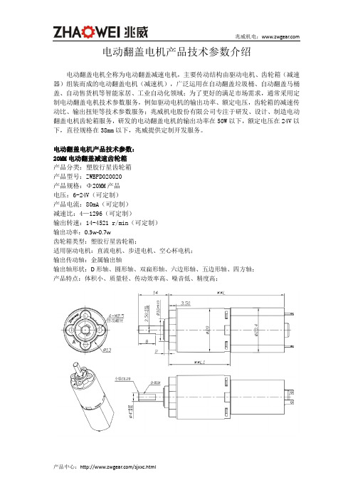
电动翻盖电机产品技术参数介绍电动翻盖电机全称为电动翻盖减速电机,主要传动结构由驱动电机、齿轮箱(减速器)组装而成的电动翻盖电机(减速机),广泛运用在自动翻盖垃圾桶、自动翻盖马桶盖、自动售货机等智能家居、工业自动化领域;为了更好的满足市场需求,通常采用定制电动翻盖电机技术参数服务,例如驱动电机的输出功率、额定电压,齿轮箱的减速传动比、输出扭矩等技术参数服务;兆威机电股份有限公司专注于研发、设计、制造电动翻盖电机齿轮箱服务,研发的电动翻盖电机的输出功率在50W以下,额定电压在24V以下,直径规格在38mm以下,兆威提供定制开发服务。
电动翻盖电机产品技术参数:20MM电动翻盖减速齿轮箱产品分类:塑胶行星齿轮箱产品型号:ZWBPD020020产品规格:Φ20MM产品电压:6-24V(可定制)产品电流:80mA(可定制)减速比:4—1296(可定制)输出转速:14-4521 r/min(可定制)输出功率:0.3w-0.7w齿轮箱类型:塑胶行星齿轮箱;适用驱动电机:直流电机、步进电机、空心杯电机;输出传动轴:金属输出轴输出轴形状:D形轴、圆形轴、双扁形轴、六边形轴、五边形轴、四方轴;产品特点:体积小、质量轻、传动效率高、噪音低、精度高;24MM电动翻盖减速齿轮箱产品分类:塑胶行星齿轮箱产品型号:ZWBPD024024产品规格:Φ24MM产品电压:12-24V(可定制)产品电流:80mA(可定制)减速比:4—1296(可定制)输出转速:14-4521 r/min(可定制)输出功率:0.05W-1.5W齿轮箱类型:塑胶行星齿轮箱;适用驱动电机:直流电机、步进电机、空心杯电机;传动输出轴:金属输出轴(可选5mm/6mm直径)输出轴形状:D形轴、圆形轴、双扁形轴、六边形轴、五边形轴、四方轴;产品特点:体积小、质量轻、传动效率高、噪音低、精度高;产品用途:电动翻盖电机主要运用在电动翻盖垃圾桶、电动翻盖马桶盖、自动售货机等智能家居、自动工业化、机械化等领域。
深圳市兆威机电有限公司介绍

对比海外企业
1、无可比拟的性能比和价格比
优势。 2、快速对应的本地化服务。
3、产品开发阶段,7天周期的快 速低成本模具开发制造力
模具制造
深圳兆威拥有一支国内一流的精密模具开发、设计、制造工程师队伍。 拥有瑞士AGIE线切割机、AGIE电火花机、MAKINO、 FANUC CNC等高精度 加工设备。
管理创新
导入ERP管理体系 深化细节, 优化流程。
以人为本
以人为本是我们企业文化的灵魂。
关注员工的成长, 关注员工的生活。
让员工乐得其所,
让“金子”都闪闪发 光。
兆威团队
没有团队的成功 就没有个人的成功!
成功=99%汗水+1%灵感
谢 谢
莅临指导
深圳市兆威机电有限公司
2008第2版
大灯调节器
成功开发了汽车大灯调节器,后视镜电动转向器等。已被福特、比亚迪 等多家国内知名企业运用
版权所有 ©2006-2008 深圳市兆威机电有限公司
汽车仪表
2010年和华中科技大学研究院合作,建立了一个由教授、博士组成的专 家团队,加强在汽车电控传动组件领域的开发、设计。
版权所有 ©2006-20轮箱等精密注塑产品。 2、微电机配件。重点发展步进电机、无刷电机。 3、超薄注塑产品:厚度0.08mm注塑件系列; 4、手机、数码相机配件:光学镜头组件;扇叶组件;
0. 1mm厚绝缘片
手机相机配件
线轴
齿轮
提
◆ 经营理念 ◆ 兆威介绍 ◆ 产品介绍 ◆ 经营策略
纲
• • • • • • • • 兆威简介 组织架构 发展里程碑 主要客户 主要产品分布图 荣誉证书 竞争优势 模具制作
版权所有 ©2006-2008 深圳市兆威机电有限公司
24V齿轮减速电机
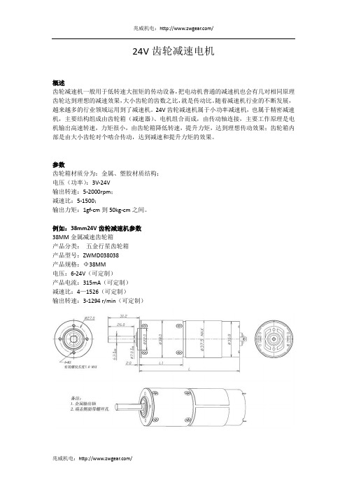
24V齿轮减速电机概述齿轮减速机一般用于低转速大扭矩的传动设备,把电动机普通的减速机也会有几对相同原理齿轮达到理想的减速效果,大小齿轮的齿数之比,就是传动比。
随着减速机行业的不断发展,越来越多的行业领域运用到了减速机。
24V齿轮减速机属于小功率减速机,也属于精密减速机,主要结构组成由齿轮箱(减速器)、电机组合而成,由传动轴连接,主要工作原理是电机输出高速转速,力矩很小,由齿轮箱降低转速,提升力矩,达到理想传动效果;齿轮箱内部是由大小齿轮对个啮合传动,达到减速和提升力矩的效果。
参数齿轮箱材质分为:金属、塑胶材质结构;电压(功率):3V-24V输出转速:5-2000rpm;减速比:5-1500;输出力矩:1gf-cm到50kg-cm之间。
例如:38mm24V齿轮减速机参数38MM金属减速齿轮箱产品分类:五金行星齿轮箱产品型号:ZWMD038038产品规格:Φ38MM电压:6-24V(可定制)产品电流:315mA(可定制)减速比:4—1526(可定制)输出转速:3-1294 r/min(可定制)性能24V齿轮减速机具备节省空间,可靠耐用,承受过载能力高,功率可达50W;能耗低,性能优越,减速机效率高达95%以上;振动小,噪音低,节能高;用途24V小功率齿轮减速机可定制参数,广泛应用在智能家居、汽车驱动器、精密医疗器械、机器人驱动、工业化自动设备、消费性电子产品、数码设备等领域。
品牌深圳市兆威机电有限公司()成立于1997年4月是一家研发、生产齿轮箱传动机构产品的高新科技企业。
为客户提供传动方案设计、零件模具设计和制造、零件生产和集成装配的采购定制服务。
电子烟升降电机参数
据《华夏时报》消息称“电子烟强制性国家标准”已经审查完毕,目前正处于批准状态,按照项目计划时间表,年内应该能发布。
随着公共场合禁烟政策严格执行以及消费者对自身健康关注导致戒烟需求上升,国内电子烟市场存在爆发可能性。
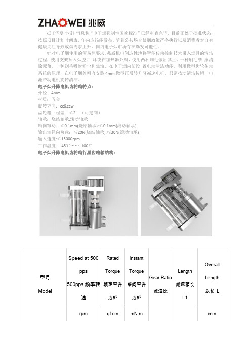
针对电子烟使用的便易性要求,兆威机电创造性地将智能传动控制技术引入烟具的清洁过程,使用支架插入烟腔并环绕在加热器外周,使用两种刷毛依附其上,一种刷毛摩擦清除死角,一种刷毛吸附粉尘和焦油,在电子烟内部设置电动清洁功能,利用微型齿轮传动系统的原理,在电子烟盖帽内安装4mm微型正反转升降减速电机,只需按动清洁按钮,电池带动电机旋转清洁。
电子烟升降电机齿轮箱特点:外径:4mm材质:五金旋转方向:cc&ccw齿轮箱回程差:≤2°(可定制)轴承:烧结轴承;滚动轴承轴向窜动:≤0.1mm(烧结轴承);≤0.1mm(滚动轴承)输出轴径向负载:≤20N(烧结轴承);≤30N(滚动轴承)输入速度:≤15000rpm工作温度:-45℃ (100)电子烟升降电机齿轮箱行星齿轮箱结构:4MM电子烟升降电机齿轮箱规格:注:参数表中的电压,转速和输出力矩只是供参考的,实际我们可以做出很多种规格,这里不一一列出,电压,转速和力矩一般都是根据客户的需求来定的,力矩要求越大。
4MM电子烟升降电机减速齿轮箱图纸:电子烟升降电机定制技术参数范围:直径规格:4mm、6mm(可定制)电压:3V-24V(可定制)功率:0.5W-50W(可定制)减速比:5-1500(可定制)扭矩范围:1gf-cm到50kgf-cm(可定制)直径范围:3.4mm-38mm(可定制)输出转速:5-2000rpm(可定制)噪音:45DB(可定制)齿轮箱材质:塑胶、金属(可定制)驱动电机:步进电机(可定制)齿轮箱传动结构:按需求定制产品特点:传动精度高、减速范围广、力矩大、质量轻、噪音低、耗能低、寿命长等优点(可定制)。
定制开发案例:项目名称:全面屏摄像头减速电机齿轮箱方案项目说明:5G时代全面屏趋势确立,前置摄像头该如何安置,我们通过行星齿轮箱3.4MM、4MM、5MM减速传动方案可以应用于后置摄像头、侧边摄像头翻转机端摄像头升降等多方案。
齿轮减速箱的原理与特点

兆威机电齿轮减速箱的原理与特点兆威机电齿轮减速箱工作原理1.齿轮减速箱是一种用于要低转速大扭矩的传动器械,齿轮减速机可以把电机等其它高速运转的动力通过齿轮减速机的的齿轮相互转换原理,把齿数少的小齿轮啮合在输出轴上齿数多的的大齿轮来达到降转速高扭力的目的,现在普通的减速机也都是由几对齿轮用相同的原理到想要的的减速效果,相对应的就是高速机,原理一个作用相反,大齿轮和小齿轮的齿数之比,也就是我们常说的动比。
2.齿轮减速箱是通过采用里面的齿轮传动装置来降低电机(马达)转速而提高输出扭力,然而变频器是通过改变电机里交流电频率;奥达到电机(马达)速度调节的作用。
两者的作用虽然一样,但使用变频器降低电机转速时,可以达到节约能源的效果但不能提高扭力。
3.齿轮减速箱是通过装在箱体内的一对啮合齿轮的转动,动力从一轴传至另一轴,实现减速的,如图2-1齿轮减速器结构图所示。
动力由电动机通过皮带轮(图中未画出)传送到齿轮轴,然后通过两啮合齿轮(小齿轮带动大齿轮)传送到轴,从而实现减速之目的。
由于传动比i = n 1 / n 2 ,则从动轴的转速n 2 = z 1 / z 2×n 1。
减速器有两条轴系——两条装配线,两轴分别由滚动轴承支承在箱体上,采用过渡配合,有较好的同轴度,从而保证齿轮啮合的稳定性。
端盖嵌入箱体内,从而确定了轴和轴上零件的轴向位置。
装配时只要修磨调整环的厚度,就可使轴向间隙达到设计要求。
2.1.1运动简图: 1——电动机2——带传动3——联轴器4——皮带式输送机 5——一级圆柱齿轮减速器兆威机电齿轮减速箱的特点齿轮减速箱具有体积小,传递扭矩大的特点。
齿轮减速箱在模块组合体系基础上设计制造,有极多的电机组合、安装形式和结构方案,传动比分级细密,满足不同的使用工况,实现机电一体化。
齿轮减速箱传动效率高,耗能低,性能优越。
1、可靠的工业用齿轮传递元件;2、可靠结构与多种输入相结合适应特殊的使用要求;3、有高的传递功率的能力而结构紧凑,齿轮结构根据模块设计原理确定;4、易于使用和维护,根据技术和工程情况配置和选择材料;。
减速电机型号参数规格介绍解读

兆威机电:/减速电机型号参数、型号、规格介绍减速电机概述减速电机是指减速机和电机(马达)的集成体。
这种集成体通常也可称为齿轮马达或齿轮电机。
通常由专业减速机厂家一站式开发人成,成套供货;减速电机按照功率分为大功率减速电机好小功率减速电机,分别应用于不同的领域。
减速电机参数小功率减速电机也称为小型减速电机、微型减速电机,例如深圳兆威机电的小型减速电机参数如下:尺寸:3mm-38mm电压:3V-24V速比:2-2000输出转速:5rpm-2000rpm输出力矩范围:1gf.cm-50kgf.cm材质:金属、塑胶材质结构减速电机型号小型减速电机型号:小型减速电机型号主要是根据尺寸、齿轮结构、材质、速比来区分的,兆威机电的小型减速电机型号主要分为四大系列:①ZWBPD系列:ZWBPD006006、ZWBPD010010、ZWBPD016016、ZWBPD020020、ZWBPD022022、ZWBPD024024、ZWBPD028028②ZWPD系列:ZWPD008008、ZWPD012012、ZWPD032032③ZWBMD系列:ZWBMD003003、ZWBMD004004、ZWBMD006006、ZWBMD010010、ZWBMD020020、ZWBMD022022、ZWBMD024024、ZWBMD028028、ZWBMD032032 ④ZWMD系列:ZWMD008008、ZWMD012012、ZWMD016016、ZWMD038038兆威机电:/兆威机电:/减速电机规格减速电机性能特点1、大多数减速电机结构紧凑,体积小,造型美观,承受过载能力强。
2、传动比分级精细,选择范围广,转速型谱宽,范围i=2-28800。
3、能耗低,性能优越,减速器效率高达百分之九十六,振动小,噪音低。
4、通用性强,是用维护方便,维护成本低,特别是生产线,只需备用内部几个传动件即可保证整线正常生产的维修保养。
5、采用新型密封装置,保护性能好,对环境适应性强,可在有高温80度、低温-10度等恶劣环境中连续工作。
24VAC电源电机技术数据说明书

† UL File XAPX.E108966Fire & Smoke damper actuator ApplicationThe type FSLF spring-return actuator is intended for the operation of smoke and combination fire and smoke dampers in ventilation and air-conditioning systems. The actuator will meet requirements of UL555 and UL555S when tested as an assembly with the damper and will meet requirements of UBC for 15 second opening and closing. Square footage of damper operated will depend on make and model and the temperature required.IMPORTANT 24VDC NOTE: The FSLF24 & -S models will not operate below 24VDC. A filtered and regulated power supply must be used.OperationMounting of the actuator to the damper axle shaft or jackshaft is via a cold-weld clamp. Teeth in the clamp and V-bolt dig into the metal of both solid and hollow shafts maintaining a perfect connection. The specially designed clamp will not crush hollow shafts. The bottom end of the actuator is held by an anti-rotation strap or by a stud provided by the damper manufacturer.The actuator is mounted in its fail safe position with the damper blade(s) closed. Upon applying power, the actuator drives the damper to the open position. The internal spring is tensioned at the same time. If the power supply is interrupted, the spring moves the damper back to its fail-safe position.The FSLF draws higher peak current when driving against its end stop or any other type of stop. Given the technology of fuses & breakers, this requires the value of fuse or breaker to be increased to avoid nuisance opening or tripping. A 1 amp slow blow should be used for 24VAC. A 0.25 amp slow blow should be used for 120VAC. A .125 amp slow blow should be used for 230V. SAFETY NOTESWiring and installation must comply with all local electrical and mechanical codes.The actuator contains no components which the user can replace or repair. Cables are not plenum rated and require flex conduit.1/2” Threaded Connector: Screw a conduit fitting into the actuator’s metal bushing. Jacket the actuator’s input wiring with suitable fl exible conduit. Properly terminate the conduit in a suitable junction box.3/8” Flex Connector (-FC models): Mount the flexible conduit into theactuator’s metal bushing by means of the provided screw with a torque of 1.2 Nm. Jacket the actuator’s input wiring with suitable flexible conduit. Properly terminate the conduit in a suitable junction box.FSLF24-S USOn/Off, Spring Return, 350°F [177°C] for a half hour, 15 Seconds Cycle TimeD a t e c r e a t e d , 03/08/2019 - S u b j e c t t o c h a n g e . © B e l i m o A i r c o n t r o l s (U S A ), I n c .Typical SpecificationAll smoke and combination fire and smoke dampers shall be providedwith Belimo FSTF, FSLF, FSNF, or FSAF actuators. All substitutions must be approved before submission of bid. Damper and actuator shall have UL 555S Listing for 250°F (350°F). Actuator shall have been tested to UL 2043 per requirements of IMC 602.2 and NEC 300.22 (c). Where position indication is required -S models with auxiliary switches or damper blade switches will be provided per code requirements.Wiring DiagramsAPPLICATION NOTESProvide overload protection and disconnect as required.45Actuators may be powered in parallel. Power consumption must beobserved.72S4 makes to S6 when actuator is powered open.73Auxiliary switches are for end position indication or interlock control.74Double insulated.75Ground present on some models.FSLF24-S USOn/Off, Spring Return, 350°F [177°C] for a half hour, 15 Seconds Cycle TimeDatecreated,3/8/219-Subjecttochange.©BelimoAircontrols(USA),Inc.。
步进电机驱动器(24VDC伺服)说明书
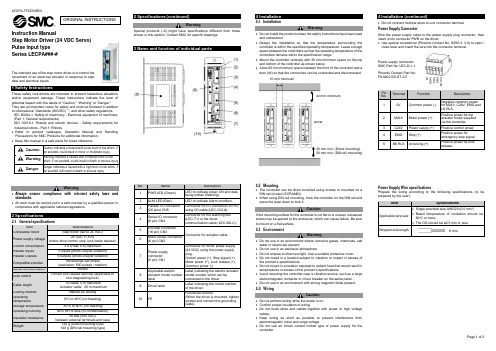
Instruction ManualStep Motor Driver (24 VDC Servo) Pulse input type Series LECPA###-#The intended use of the step motor driver is to control the movement of an electrical actuator in response to step data and electrical inputs.These safety instructions are intended to prevent hazardous situations and/or equipment damage. These instructions indicate the level of potential hazard with the labels of “Caution,” “Warning” or “Danger.”They are all important notes for safety and must be followed in addition to International Standards (ISO/IEC) *1), and other safety regulations.IEC 60204-1: Safety of machinery - Electrical equipment of machines. (Part 1: General requirements)ISO 10218-1: Robots and robotic devices - Safety requirements for industrial robots - Part 1: Robots.• Refer to product catalogue, Operation Manual and Handling Precautions for SMC Products for additional information. • Keep this manual in a safe place for future reference.CautionCaution indicates a hazard with a low level of risk which, if not avoided, could result in minor or moderate injury.WarningWarning indicates a hazard with a medium level of riskwhich, if not avoided, could result in death or serious injury.DangerDanger indicates a hazard with a high level of risk which, ifnot avoided, will result in death or serious injury.Warning• Always ensure compliance with relevant safety laws and standards.• All work must be carried out in a safe manner by a qualified person in compliance with applicable national regulations.2.1General specificationsItemSpecificationsCompatible motorStep motor (servo 24 VDC)Power supply voltage24 VDC +/-10%(motor drive control, stop, lock brake release).Current consumption 3 A (Peak 5 A) maximum Parallel Inputs 5 inputs (photo-coupler isolation) Parallel Outputs 9 outputs (photo-coupler isolation)Compatible encoderIncremental A/B phase(resolution: 800 pulses / rotation)Serial communication RS485Lock controlForced lock release terminal (applicable tonon-magnetizing lock). Cable lengthIO cable: 5 m maximumActuator cable: 20 m maximumCooling method Natural air-cooling Operatingtemperature0o C to 40o C (no freezing)Storage temperature -10o C to 60o C (no freezing) Operating humidity 90% RH or less (no condensation)Insulation resistance50 MΩ (500 VDC)between external terminals and caseWeight120 g (Direct mounting type)140 g (DIN rail mounting type)WarningSpecial products (-X) might have specifications different from those shown in this section. Contact SMC for specific drawings.4 Installation4.1 InstallationWarning• Do not install the product unless the safety instructions have been read and understood.• Design the installation so that the temperature surrounding the controller is within the specified operating temperature. Leave enough space between the controllers so that the operating temperature of the controllers remains within the specification range.• Mount the controller vertically with 30 mm minimum space on the top and bottom of the controller as shown below.• Allow 60 mm minimum space between the front of the controller and a door (lid) so that the connectors can be connected and disconnected.4.2 Mounting• The controller can be direct mounted using screws or mounted on a DIN rail (model LECPA##D).• When using DIN rail mounting, hook the controller on the DIN rail and press the lever down to lock it.CautionIf the mounting surface for the controller is not flat or is uneven, excessive stress may be applied to the enclosure, which can cause failure. Be sure to mount on a flat surface. 4.3 EnvironmentWarning• Do not use in an environment where corrosive gases, chemicals, salt water or steam are present.• Do not use in an explosive atmosphere.• Do not expose to direct sunlight. Use a suitable protective cover.• Do not install in a location subject to vibration or impact in excess of the product’s specifications.• Do not mount in a location exposed to radiant heat that would result in temperatures in excess of the product’s specifications.• Avoid mounting the controller near a vibration source, such as a large electromagnetic contactor or circuit breaker on the same panel. • Do not use in an environment with strong magnetic fields present. 4.4 WiringCaution• Do not perform wiring while the power is on. • Confirm proper insulation of wiring.• Do not route wires and cables together with power or high voltage cables.• Keep wiring as short as possible to prevent interference from electromagnetic noise and surge voltage.• Do not use an inrush current limited type of power supply for the controller.• Do not connect multiple wires to one connector terminal.Power Supply ConnectorWire the power supply cable to the power supply plug connector, then insert it into connector PWR on the driver.• Use special screwdriver (Phoenix Contact No. SZS0.4×2.0) to open / close lever and insert the wire into the connector terminal.Power Supply Wire specificationsPrepare the wiring according to the following specifications (to be prepared by the user).ORIGINAL INSTRUCTIONSPower supply connector. SMC Part No. LEC-D-1-1. Phoenix Contact Part No: FK-MC0.5/5-ST-2.510 mm minimum Driver30 mm min. (Direct mounting) 50 mm min. (DIN rail mounting)30 mm minimumParallel I/O Connector• When connecting the parallel I/O connector to a PLC use an SMC parallel I/O cable (LEC-CL5-#).• There are 2 types of parallel I/O with this controller: NPN type and PNP type. Check the polarity required before use.The parallel I/O wiring should be prepared according to the polarity.For further details of the Parallel I/O wiring refer to the Operation Manual on the SMC website (URL: https:// ).4.5 Ground connection• Place a ground cable with crimped terminal under one of the M4 mounting screws with a shakeproof washer and tighten the screw.CautionThe M4 screw, cable with crimped terminal and shakeproof washer must be prepared by the user.The controller must be connected to Ground to reduce noise. If higher noise resistance is required, ground the 0 V (signal ground). When grounding the 0 V, avoid flowing noise from ground to 0 V.• A dedicated Ground connection must be used. Grounding should be to a D-class ground (ground resistance of 100 Ω maximum).• The cross-sectional area of the ground cable shall be 2 mm 2 minimum. • The Grounding point should be as near as possible to the controller. Keep the grounding cable as short as possible.In order to move the electric actuator to a specific position, it is necessary to set up the patterns of operation with a PC using the controller setting software or by using a teaching box. This set up data will be recorded in the memory of the controller.Step data describes the data that sets items of operation (such as positioning width) excluding speed, position, acceleration, and deceleration, which are determined by the pulse-signal input. Step data will become effective as soon as it is recorded into the driver.Refer to the Operation Manual on the SMC website (URL: https:// ) for further setting details.Refer to the table below for details of the LED status.LEDDescriptionPWROFFPower is not supplied Green LED is ON Power is suppliedGreen LED is flashingEEPROM memory writing ALM OFFNormal operationRed LED is ONController Alarm generated7 How to OrderRefer to the catalogue on the SMC website (URL: https:// ) for the How to Order information.8 Outline Dimensions (mm)Refer to the drawings / operation manual on the SMC website (URL: https:// ) for outline dimensions.9 Maintenance9.1 General MaintenanceCaution• Not following proper maintenance procedures could cause the product to malfunction and lead to equipment damage.• Before performing maintenance, turn off the power supply. Check the voltage with a tester 5 minutes after the power supply is turned OFF. • If any electrical connections are disturbed during maintenance, ensure they are reconnected correctly and safety checks are carried out as required to ensure continued compliance with applicable national regulations.• Do not make any modification to the product.• Do not disassemble the product, unless required by installation or maintenance instructions.Caution• Maintenance should be performed according to the procedure indicated in the Operation Manual.• When equipment is serviced, first confirm that measures are in place to prevent dropping of work pieces and run-away of equipment, etc, then cut the power supply to the system. When machinery is restarted, check that operation is normal with actuators in the correct position.Warning• Perform maintenance checks periodically.• Confirm wiring and screws are not loose. Loose screws or wires may cause unexpected malfunction.• Conduct an appropriate functional inspection and test after completing maintenance. In case of any abnormalities (if the actuator does not move, etc.), stop the operation of the system. Otherwise, an unexpected malfunction may occur and it will become impossible to ensure safety. Operate an emergency stop instruction to confirm safety. • Do not put anything conductive or flammable inside of the controller. • Ensure sufficient space around the controller for maintenance.10 Limitations of Use10.1 Limited warranty and Disclaimer/Compliance Requirements Refer to Handling Precautions for SMC Products.11 Product disposalThis product shall not be disposed of as municipal waste. Check your local regulations and guidelines to dispose of this product correctly, in order to reduce the impact on human health and the environment.12 ContactsRefer to or www.smc.eu for your local distributor / importer.URL: https:// (Global) https://www.smc.eu (Europe) SMC Corporation, 4-14-1, Sotokanda, Chiyoda-ku, Tokyo 101-0021, Japan Specifications are subject to change without prior notice from the manufacturer. © 2021 SMC Corporation All Rights Reserved. Template DKP50047-F-085MPin No. Insulation Colour Dot mark Dot colour Category Signal 1 Light brown ● Black 24 V COM+ 2 Light brown ● Red 0 V COM- 3 Yellow ● Black Pulse signal NP+ 4 Yellow ● Red Pulse signal NP- 5 Light green ● Black Pulse signal PP+ 6 Light green ● Red Pulse signal PP- 7 Grey ● Black Input SETUP 8 Grey ● Red Input RESET 9 White ● Black Input SVON 10 White ● Red Input CLR 11 Light brown ●● Black Input TL 12 Light brown ●● Red Output TLOUT 13 Yellow ●● Black Output WAREA 14 Yellow ●● Red Output BUSY 15 Light green ●● Black Output SETON 16 Light green ●● Red Output INP 17 Grey ●● Black Output SVRE 18 Grey ●● Red Output ESTOP19White ●● Black Output ALARM 20White ●● Red Output AREA。
- 1、下载文档前请自行甄别文档内容的完整性,平台不提供额外的编辑、内容补充、找答案等附加服务。
- 2、"仅部分预览"的文档,不可在线预览部分如存在完整性等问题,可反馈申请退款(可完整预览的文档不适用该条件!)。
- 3、如文档侵犯您的权益,请联系客服反馈,我们会尽快为您处理(人工客服工作时间:9:00-18:30)。
深圳市兆威机电有限公司
减速电机产品型号:ZWPD024024
减速电机产品规格:Φ24MM
减速电机产品类型:行星齿轮箱
减速电机产品电流:40mA
减速电机输出转速:可参照下面的详细参数
减速电机产品电压:12V
减速电机产品材料:塑胶
减速电机减速比:可参照下面的详细参数
24毫米行星减速电机重要图纸与参数
24毫米行星减速电机产品的主要用途:深圳兆威生产的24毫米行星减速电机主要用在各种光学设备、医疗设备、广告旋转传动、银行提款机等微型机械产生上。
24毫米行星齿轮减速电机的输出功率大约在0.2W-25W,而齿轮箱的最大承载力为63.7Kg.
24毫米行星减速电机的图纸:
24毫米行星减速电机齿轮箱电机的参数对比表:
表1: 12V 齿轮箱的电机数据参考表:。
